2. Literature Review
The presence of an aft-deck significantly influences the nature of the jet emanating from a rectangular nozzle. For an underexpanded jet with a series of expansion and shock waves, interaction with the aft-deck surface alters the shock pattern and entrainment characteristics, including shear-layer growth and jet plume trajectory [
1]. The flow field issuing from rectangular nozzles with an aft-deck depends on various factors such as nozzle pressure ratio (NPR), aft-deck length, exit aspect ratio, exit velocity profile, exit turbulence intensity, exit Reynolds number, and ambient conditions [
14].
Experimental work by Behrouzi and McGuirk [
1] examined supersonic flows from a convergent rectangular nozzle (aspect ratio 7.35) fitted with an aft-deck extension. Their experimental work revealed several key findings: the attachment of an aft-deck produced a slight lengthening of the potential core while simultaneously lowering turbulence intensities within the near-field region. Measurements indicated that asymmetry developed in both shock cell configurations and entrainment patterns within shear regions due to the aft-deck’s presence. This asymmetrical development resulted in a lateral force component acting on the jet through alterations to inviscid shock cell dynamics. These alterations to force distribution on the jet resulted in lateral movement of the jet plume, with directional behavior (either up or down) determined by operating pressure ratio. Between NPR values of 2.45 and 3.0, they documented stabilization effects on flow where flapping phenomena driven by screech had been observed in configurations without aft-decking. Through testing various aft-deck lengths, they documented separation zone formation on the longest configuration at elevated NPR conditions.
Kopriva et al. [
15] employed Lattice Boltzmann computational techniques to model transonic jets (NPR = 1.89 and 2.45) from rectangular discharge geometries with and without aft-deck extensions. Their computational studies included evaluation of different boundary condition implementations at the nozzle exit, with optimal correlation to experimental data achieved using no-slip conditions with uniform profile assumptions. Their investigation into aft-deck length effects revealed that extending the aft-deck generated more extensive shock trains through reflection mechanisms, extended the potential core region, and produced downstream flow field modifications resulting in asymmetrical mean velocity distributions for all tested geometries. The most pronounced profile asymmetry occurred with the
configuration, producing upward jet plume deflection, while other configurations (
and
) resulted in downward deflection.
The effect of aft-decks on flow characteristics from a shallow single-curved convergent nozzle across NPRs of 1.1–2.2 was investigated by Rajkumar et al. [
16]. This work, along with subsequent investigations by Nageswara and Kushari [
17], demonstrated that incorporating aft-decks fundamentally changes expansion wave reflection physics—specifically preventing expansion fans originating at nozzle-exit edges from developing into compression waves, which substantially modifies shock structures. Rajkumar et al. [
16] noted boundary layer growth acceleration caused by the aft-deck, leading to core flow acceleration and premature flow choking at lower pressure ratios than otherwise expected.
Nageswara and Kushari [
17] extended this research through experimental evaluation of elliptical exit geometries with aft-decks under underexpanded conditions (NPR = 2–4). They observed that aft-deck installations stabilized flapping instabilities (induced by screech phenomena) present in both circular exits and truncated elliptical configurations by reducing shock intensity within the potential core. Their measurements at NPR = 3 and 4 showed reduced potential core length and enhanced spreading characteristics for truncated elliptical configurations compared to aft-deck variants, attributable to vortical structure amplification through screech mechanisms not present in aft-deck configurations. Their work also documented flow separation and subsequent reattachment processes occurring on the aft-deck surface at elevated NPR operations.
Through combined schlieren visualization and pressure measurements, Tammabathula et al. [
18] investigated how wall length (
= 0.5, 1, 2, 4 and 8) affects decay patterns and shock formations in supersonic wall jets from a convergent–divergent nozzle with a square exit profile operating at NPR = 6. Their research demonstrated that wall installations consistently reduced supersonic core extent compared to free-jet configurations, with this effect observed across all wall length variations. Maximum reductions in core length and enhanced decay characteristics were documented at
. Increasing wall length to 1
resulted in observable reductions in decay rate and partial recovery of supersonic core length. Wall presence altered pressure gradient distributions, creating steeper gradients near the exit region but more gradual pressure declines at downstream locations when
. Wall installations also affect shock structure and plume direction. Walls up to
in length steer the jet upward, whereas a
wall deflects it downward and longer walls have negligible influence on the trajectory. Significant modifications to shock patterns were primarily limited to wall lengths below 2
.
The apparent contradiction between Behrouzi and McGuirk [
1] and Tammabathula et al. [
18] merits consideration. Behrouzi and McGuirk [
1] observed an increased potential core length with an aft-deck, whereas Tammabathula et al. [
18] reported that walls always reduce the supersonic core length. This discrepancy likely stems from differences in experimental configurations: Behrouzi and McGuirk used a convergent rectangular nozzle at moderate NPR = 2.45–3.0, yielding an underexpanded jet, while Tammabathula et al. [
18] employed a convergent–divergent nozzle with a square exit at NPR = 6, producing an overexpanded jet. The distinct nozzle geometries and expansion states (under- vs. over-expanded), together with the different pressure conditions, lead to fundamentally different shock–boundary-layer interactions, highlighting the strongly condition-dependent nature of aft-deck effects on supersonic jets.
Experimental investigations by Manikanta and Sridhar [
19] assessed interactions between rectangular supersonic jets and flat surfaces with various wall length configurations. Under overexpanded conditions (NPR = 4), they found that walls of shorter length (
) generated downward jet plume redirection, with peak negative deflection angles reaching −2.6° at
. In contrast, underexpanded flow conditions (NPR = 8) consistently produced upward deflection regardless of wall extension length up to 4
, with maximum positive deflection (7.1°) occurring at
. At near-optimal expansion (NPR = 6), they observed predominantly upward deflection patterns at most lengths tested, with the exception of the 2
configuration which produced modest downward movement (−1.2°). Their systematic evaluation revealed minimal force coefficient effects from wall extensions beyond 4
, and limited influence on upstream shock development from wall length variations beyond 2
across all expansion conditions tested.
Numerical studies by Jiao et al. [
20] explored how aft-deck angle influences flow characteristics in serpentine nozzle configurations. Their analysis revealed that upward-angled aft-decks could generate static pressure variations up to 7% under underexpanded operating conditions. Through assessment of multiple pressure ratios (NPR = 1.5, 3, and 4.5), they documented thrust vector angle variations of up to 18° depending on aft-deck configuration, with optimal thrust coefficient values achieved when the thrust vector approached axial alignment. Their work identified specific transition patterns in separation behavior, with closed separation regions forming at moderate deck angles while open separation developed at more aggressive negative angles (exceeding −8°).
Research conducted by Chen et al. [
21] on variable aspect ratio rectangular nozzles incorporating aft-decks provided important insights into flow dynamics. At lower NPR values (between 2 and 3), they documented that increasing the nozzle aspect ratio enhanced incident shock wave strength without modifying other flow parameters, facilitating successful boundary layer separation and subsequent reattachment on the aft-deck surface. This phenomenon was evidenced by characteristic plateau-shaped pressure distributions typical of strong interactions between shocks and boundary layers. Their investigations revealed that with NPR = 3, aspect ratios of 6.77 and 7.54 produced downward jet plume movement, while further increasing to 8.35 resulted in horizontal discharge patterns. When NPR was increased to 4, they observed that shock strength became sufficient to promote early separation without subsequent reattachment, leading to horizontal jet plume discharge patterns regardless of which aspect ratio was employed.
The pressure distribution on the aft-deck surface plays a crucial role in determining jet deflection behavior. Nageswara and Kushari [
17] observed that at NPR = 4, flow separation occurred beyond
on the aft-deck surface, with the separation region growing with increasing NPR. Manikanta and Sridhar [
19] reported that at NPR = 4, the region near the nozzle exit consistently showed sub-atmospheric pressure for all wall lengths, with pressure peaks decreasing along the wall length. At NPR = 6, they observed a continuous decline in wall pressure from the leading edge, with the location of minimum wall pressure shifting from 0.5
to 1.8
as wall length increased beyond 2
.
Behrouzi and McGuirk [
1] found that the aft-deck modified the shock cell structure, both in location and oscillation amplitude, which affected the development of saddle-shaped velocity profiles, typical of rectangular jets, by suppressing inward movement of velocity peaks. Chen et al. [
21] compared three geometrically similar nozzle–aft-deck models that differed only in nozzle-exit aspect ratio, namely
,
, and
. At
, the
model showed a pressure rise at
, indicating separation without reattachment, whereas the
and
models exhibited plateau-like pressure distributions between
and
. When the pressure ratio was increased to
, the onset of separation moved upstream: the
configuration separated near
, while the
and
configurations separated closer to
.
The acoustic characteristics of aft-deck configurations have also been extensively studied. Bridges [
22] provided a systematic experimental investigation comparing two approaches to studying acoustic effects—integrated beveled nozzles and separate plate configurations. He found that the additional noise from the extended deck exhibits a sixth-power velocity dependence, characteristic of dipole sources, in contrast to the eighth-power scaling of jet mixing noise. The observation of strong tonal features in the separate plate configuration, which were absent in previous studies with integrated surfaces, suggested additional complexity in the flow–acoustic coupling. For rectangular nozzles without aft-decks, increasing aspect ratio reduced noise, with the 8:1 nozzle showing up to 3 dB reduction compared to the baseline round nozzle in the major axis plane. However, this benefit was negated by the addition of an aft-deck. The beveled nozzle configuration with the longest deck (
= 1.25) increased noise by up to 8 dB above the baseline 8:1 nozzle without bevel in the major axis plane, while only adding 3 dB in the minor axis plane.
Nageswara and Kushari [
17] found that the addition of an aft-deck to an elliptical nozzle produced substantial modifications to both flow structure and noise characteristics, with reduction in screech tone amplitudes by 26 dB compared to the truncated elliptical configuration. This was achieved through the modification of shock reflection patterns where expansion waves from the nozzle exit reflect as expansion waves rather than compression waves off the aft-deck surface.
Applications of aft-deck configurations in aerospace engineering have been demonstrated in several studies. Lee and Choi [
12] studied the effects of aft-deck geometry on plume shield ratio in turbofan engines. They found that the plume shield ratio improved from 3.5% for 1.0
aft-deck length to 8.5% for 1.5
, though it slightly decreased to 7.5% for 2.0
, indicating an optimal configuration around 1.5
. Their thrust measurements showed modest performance penalties with increased aft-deck length: the baseline configuration without aft-deck (0.0
) produced 6.440 kN thrust, while configurations with 1.0
, 1.5
, and 2.0
aft-decks generated 6.382 kN, 6.380 kN, and 6.376 kN, respectively, representing approximately a 1% thrust reduction.
Afilaka [
23] presented a Normal-Blowing Fluidic Thrust Vectoring approach for supercritical aft-deck nozzles. For symmetric nozzles, maximum vectoring angle of 12° was achieved at NPR = 2.6 with a system gain of 2, while skewed nozzles demonstrated superior performance with 14° vectoring and system gain of 6.5 at the same conditions. The system gain here is defined as the ratio of useful vertical momentum generated to momentum injected by the blowing jets. The skewed geometry consistently generated approximately 10% higher vertical force coefficients compared to symmetric configurations due to improved flow attachment.
Significant advancements in understanding rectangular supersonic jets with aft-decks have been achieved. However, several research gaps remain. While many studies have investigated the individual effects of aft-deck length and nozzle pressure ratio (NPR) on jet plume deflection, far fewer have systematically examined the combined influence of exit aspect ratio, aft-deck length, and NPR. In addition, the relationship between shock–boundary-layer interaction and plume deflection—particularly the transition between attached and separated flow regimes—still requires clarification. Previous experiments illustrate this variability. Behrouzi and McGuirk [
1], Chen et al. [
21], and Jiao et al. [
20] documented deflection phenomena across a wide range of conditions, yet the underlying mechanisms, especially the directional reversal observed at higher NPR, remain insufficiently explained.
Table 1 summarises key observations. For example, Behrouzi and McGuirk found that at
, a long aft-deck
yielded upward deflection, whereas shorter decks produced downward or neutral trends. Kopriva et al. [
15] numerically reproduced this behaviour. Manikanta and Sridhar [
19] showed that at
, short walls
caused downward vectoring, but longer walls
reversed the sign; the pattern shifted again at higher NPR. Chen et al. demonstrated that exit aspect ratio alone could invert deflection: at
, downward deflection appeared for
and
, while
produced a nearly horizontal plume, and at
, deflection ceased for all ARs because separation prevented reattachment. Collectively, these findings confirm that deflection depends jointly on NPR, aft-deck length, and nozzle geometry.
The present study addresses the remaining gaps by identifying and quantifying the flow mechanisms that create the transverse pressure gradients responsible for jet plume deflection in underexpanded rectangular jets with aft-decks. By systematically varying aft-deck length and NPR, this work aims to correlate these specific flow features with the resulting deflection angles and to resolve the competing hypotheses.
3. Materials and Methods
This study employed computational fluid dynamics (CFD) to investigate supersonic rectangular jets with an aft-deck. The methodology consisted of developing a validated numerical model to use in a parametric investigation across various nozzle pressure ratios and aft-deck geometries. The rectangular nozzle considered in this study is identical to that used by Behrouzi and McGuirk [
1]. The nozzle exit hydraulic diameter
is 22.46 mm. While the original nozzle had a three-dimensional geometry with an aspect ratio of 7.35, the present investigation simplified this to a two-dimensional configuration by considering the minor axis plane geometry. This simplification is justified as rectangular jets with aspect ratios greater than 7 exhibit shock structures and velocity decay profiles comparable to two-dimensional jets, except near the lateral edges [
24] and downstream due to limited jet spreading in 2D jets compared to 3D jets.
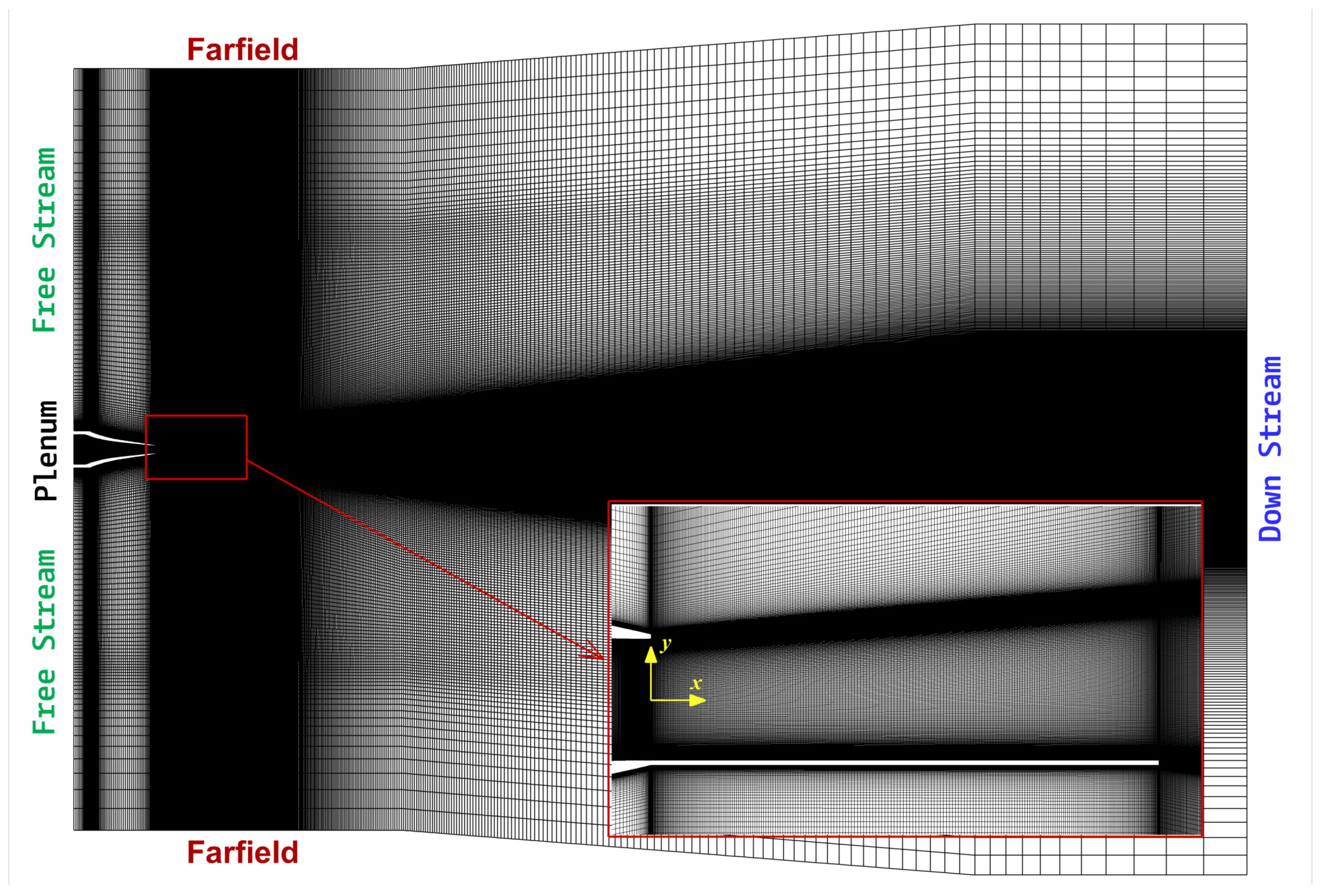
The numerical boundary conditions, shown in
Figure 1, include multiple pressure inlets, a pressure outlet, and solid wall boundaries. The plenum boundary, defined as a pressure inlet, has a total pressure that varies with the nozzle pressure ratio (NPR), calculated as NPR multiplied by the free-stream pressure of 100,000 Pa. For example, at NPR = 3.5, the inlet total pressure is 350,000 Pa. The total temperature at this boundary is maintained at 300 K. The downstream boundary, designated as a pressure outlet, has a total pressure of 100,000 Pa, with a backflow temperature of 300 K. The farfield boundaries are modeled as pressure inlets, and have a total pressure of 100,000 Pa. The turbulence parameters for these boundaries include a turbulent intensity of 2% and a turbulent length scale of 0.01 m. Finally, the nozzle walls boundaries, including the aft-deck, are modeled as no-slip, adiabatic walls.
The coupled pressure-based solver in Ansys Fluent 2019 was used to carry out all the simulations. The solver implements second-order pressure–velocity coupling and second-order upwind scheme for all flow equations including the k- SST turbulence model equations. The shear stress transport (SST) model was selected to ensure reliable predictions of separation onset and reattachment along the aft-deck surface. The SST formulation combines the advantages of the standard model near the wall with the behavior in the outer region. Additionally, with at the wall (as in the present simulations), the SST model fully resolves the viscous sublayer and avoids wall function approximations.
To enhance numerical stability in the presence of strong compressibility effects, a global time step approach was utilized with the pseudo-time method. Solution convergence criterion was set at for all variables. This numerical setup along with the selected boundary conditions was found to produce the best possible and stable results. Viscosity was computed using Sutherland’s law.
3.1. Grid Independence
The 2D computational domain is shown in
Figure 1. The nozzle exit is positioned at
with its centerline at
. The aft-deck is located in the negative
y-axis region. The outer limits are set to
and
. The mesh is clustered along the nozzle interior and the aft-deck to resolve shock–boundary-layer interaction and near-wall shear. The average streamwise spacing is
in the nozzle
and
on the aft-deck
. The first wall-normal spacing is
which ensures dimensionless wall distance
.
A grid independence study was implemented to ensure accurate resolution of flow features. Near-wall refinement was applied to capture boundary layer phenomena.
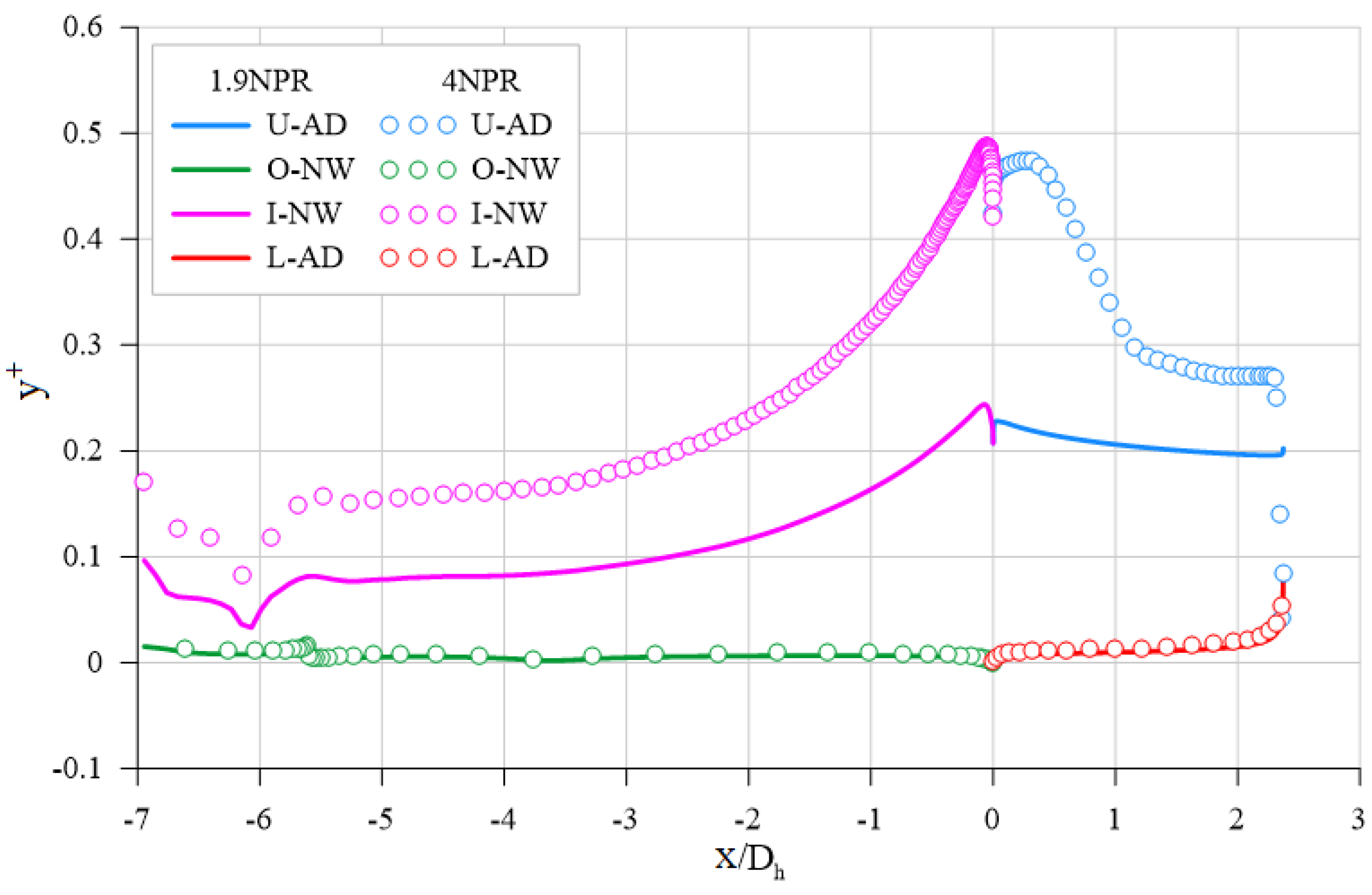
Figure 2 presents
distribution along the normalized streamwise coordinate (
) for aft-deck length of 2.37
at NPR values of 1.9 and 4.0. The
values remain below 1.0 which satisfies the requirement for resolving the viscous sublayer.
Moreover, the mesh density in the shock cell region was varied in the streamwise direction to enhance the detail of the captured flow field. These modifications served as the foundation for the grid independence tests. Three different mesh densities were generated, categorized as coarse, medium, and refined, as shown in
Table 2.
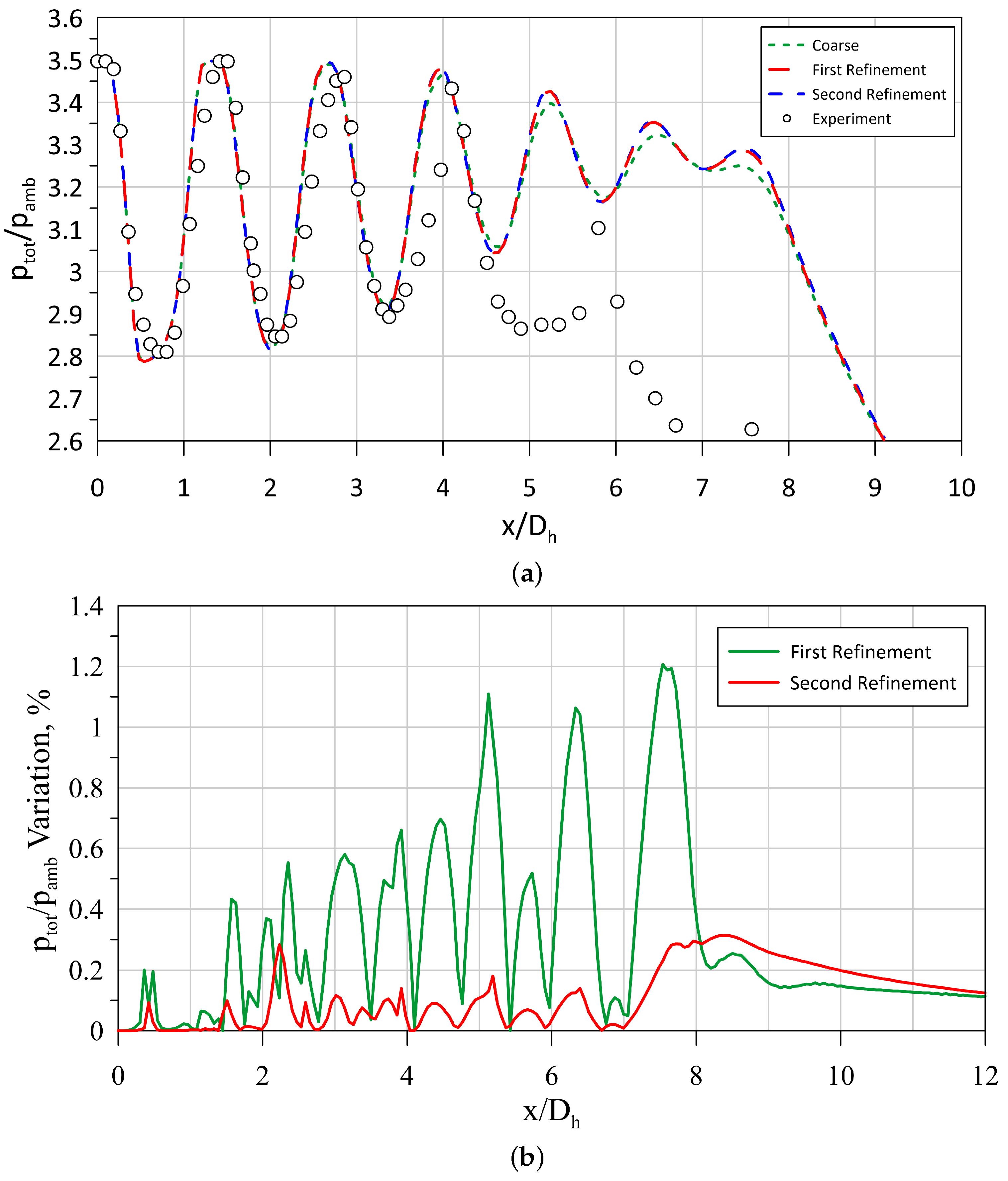
The non-dimensional Pitot pressure along the centerline of the jet for the configuration without an aft nozzle at 3.5 NPR is presented in
Figure 3a. The figure demonstrates that the medium grid resolved the centerline velocity nearly as accurately as the finest mesh. Additionally,
Figure 3b illustrates the percentage variation. The figure shows that the difference in variation between the fine and medium (second refinement) grids is much smaller compared to the variation between the coarse grid and the medium grid (first refinement). As a result, all subsequent simulations were conducted using the medium grid density.
3.2. Validation
The medium mesh selected based on the grid independence study was used for validation purposes. The CFD validation criteria were based on the data reported from the experiment carried out by Behrouzi and McGuirk [
1], which includes flow field images, aft-deck static pressure distribution, centerline Pitot pressure, and jet velocity profiles at two different streamwise locations (
= 5 and 10).
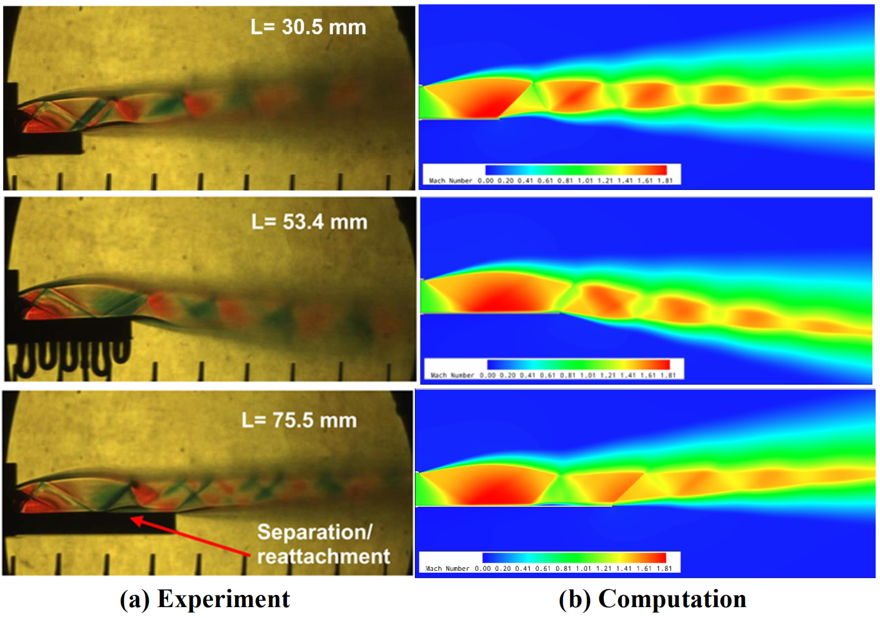
Figure 4 compares computational Mach number contours with experimental Schlieren images across three normalized aft-deck configurations (1.36
, 2.37
, and 3.37
). The numerical simulations reproduce the principal flow features visible in the experimental data. Shock diamond structures display consistent spacing and positioning in both datasets. The computational model represents the primary expansion fan emanating from the nozzle exit. Shock reflections along the aft-deck surface appear in both visualization methods with minor positional differences. The separation/reattachment region on the 3.37
aft-deck configuration exists in both experimental and numerical results. The exact location of this region varies slightly between the datasets. The figure also illustrates the numerical model’s capability to capture the experimentally measured jet core deflection with high fidelity. Both approaches show increased shock reflection complexity with greater aft-deck length. The correspondence between computational and experimental results indicates the numerical methodology resolves the fundamental supersonic flow physics for the tested configurations.
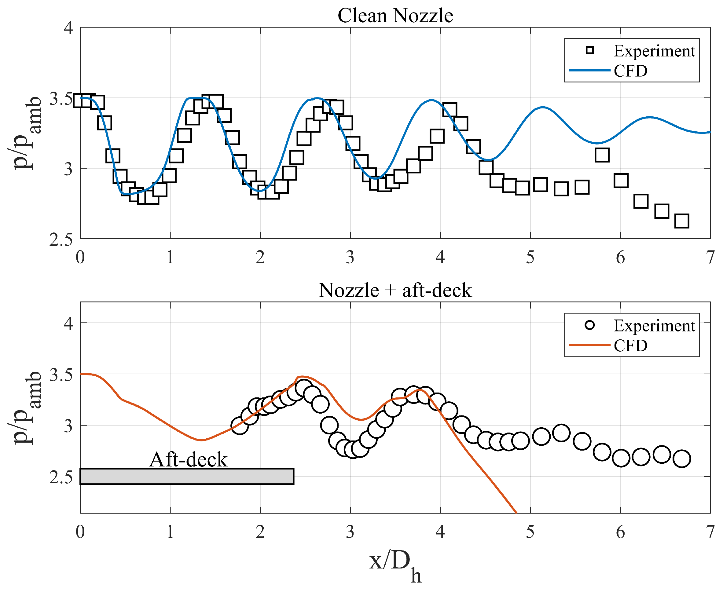
Figure 5 illustrates the centerline Pitot pressure distributions for supersonic jets with and without an aft-deck. For the clean nozzle configuration (without an aft-deck), CFD accurately predicts the initial shock cell structure up to
, with good agreement in both amplitude and wavelength; however, beyond this region, the simulation fails to capture the experimental pressure decay due to inadequate modeling of three-dimensional mixing effects. Similarly, in the aft-deck case, while numerical predictions align with experimental data up to
, the CFD dramatically underpredicts the pressure distribution downstream, showing a sharp decline compared to the experimental values. This significant discrepancy stems from both the numerical overestimation of jet deflection in the aft-deck configuration and the fundamental inability of two-dimensional simulations to capture the enhanced mixing and spreading in the three-dimensional flow.
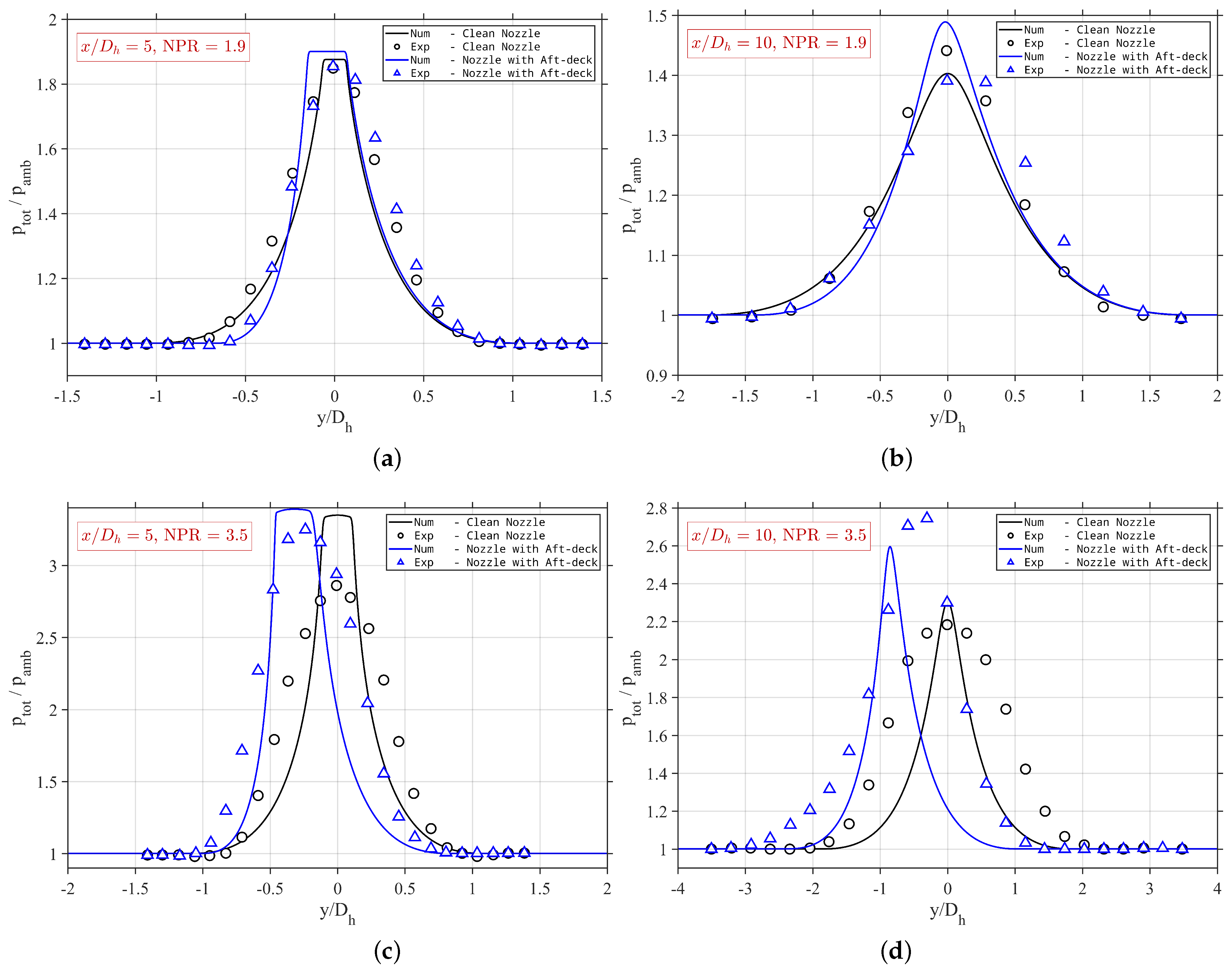
Figure 6 compares numerical and experimental jet spreading profiles for supersonic jets with and without an aft-deck at various downstream stations and NPR conditions. The numerical simulation accurately predicts jet spreading for clean nozzles at perfectly expanded conditions (
); however, it fails to capture the slight positive deflection in aft-deck configurations observed experimentally. At
, the 2D assumption limitations become significant, with calculations underestimating jet spreading at both
and
axial locations. The simulations predict higher peak pressure magnitudes than experimental measurements, indicating delayed pressure recovery. The numerical simulation also overpredicted jet deflection in the aft-deck configuration. These discrepancies in spreading prediction and overestimation of jet deflection in aft-deck cases result directly from the 2D simulations’ inability to model enhanced mixing and three-dimensional flow structures present in experimental conditions.
Figure 7 compares the non-dimensional static pressure results from CFD simulations and experimental data on the 2.37
aft-deck. Overall, the two results align closely, except at the nozzle, where the CFD simulation shows an overprediction of the exit pressure. Several factors may contribute to this discrepancy, including differences in initial conditions such as turbulence levels and momentum thickness, which can vary between 2D and 3D flow from a nozzle.
The two-dimensional numerical simulations accurately reproduces fundamental flow structures including shock diamond patterns, expansion fans, and shock reflections in both clean nozzle and aft-deck configurations. Near-field flow characteristics show good agreement with experimental data. The numerical approach correctly predicts the direction of jet deflection. However, it overestimates jet deflection in aft-deck configurations and fails to capture downstream pressure decay due to its inherent inability to model three-dimensional mixing effects. The approach demonstrates sufficient validity for exploratory studies into jet deflection mechanisms while recognizing that fully accurate quantitative predictions would require three-dimensional simulations.
4. Results
This study investigates the physics governing jet deflection in rectangular supersonic jets with aft-decks. The analysis examines a dataset of 117 configurations, consisting of nine aft-deck lengths (, , , , , , , , and ) and thirteen nozzle pressure ratios (NPR = 1.9, then 2.25 to 5.0 in steps of 0.25).
To establish a systematic understanding, we begin by presenting a global view of the deflection behavior across the parameter space.
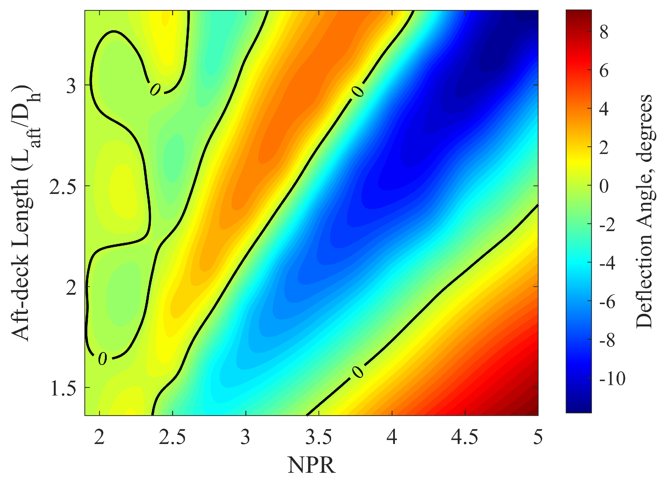
Figure 8 shows the jet deflection angle as a function of nozzle pressure ratio (NPR) and normalized aft-deck length (
). The figure shows a complex, non-monotonic relationship. Of particular significance are the multiple zero-deflection contours (black lines) that mark the transition between upward and downward deflection. These contours represent critical states where competing mechanisms achieve perfect balance.
From the 117 cases in the complete dataset, 12 representative case were selected for detailed analysis. The selected NPR values are (1.9, 2.5, 3.5, and 4.5) over three aft-deck lengths (
,
, and
) investigated experimentally by Behrouzi and McGuirk [
1]. The selection enables the examination of how NPR affects flow for a fixed aft-deck length and we can compare aft-deck length effects at identical NPR conditions.
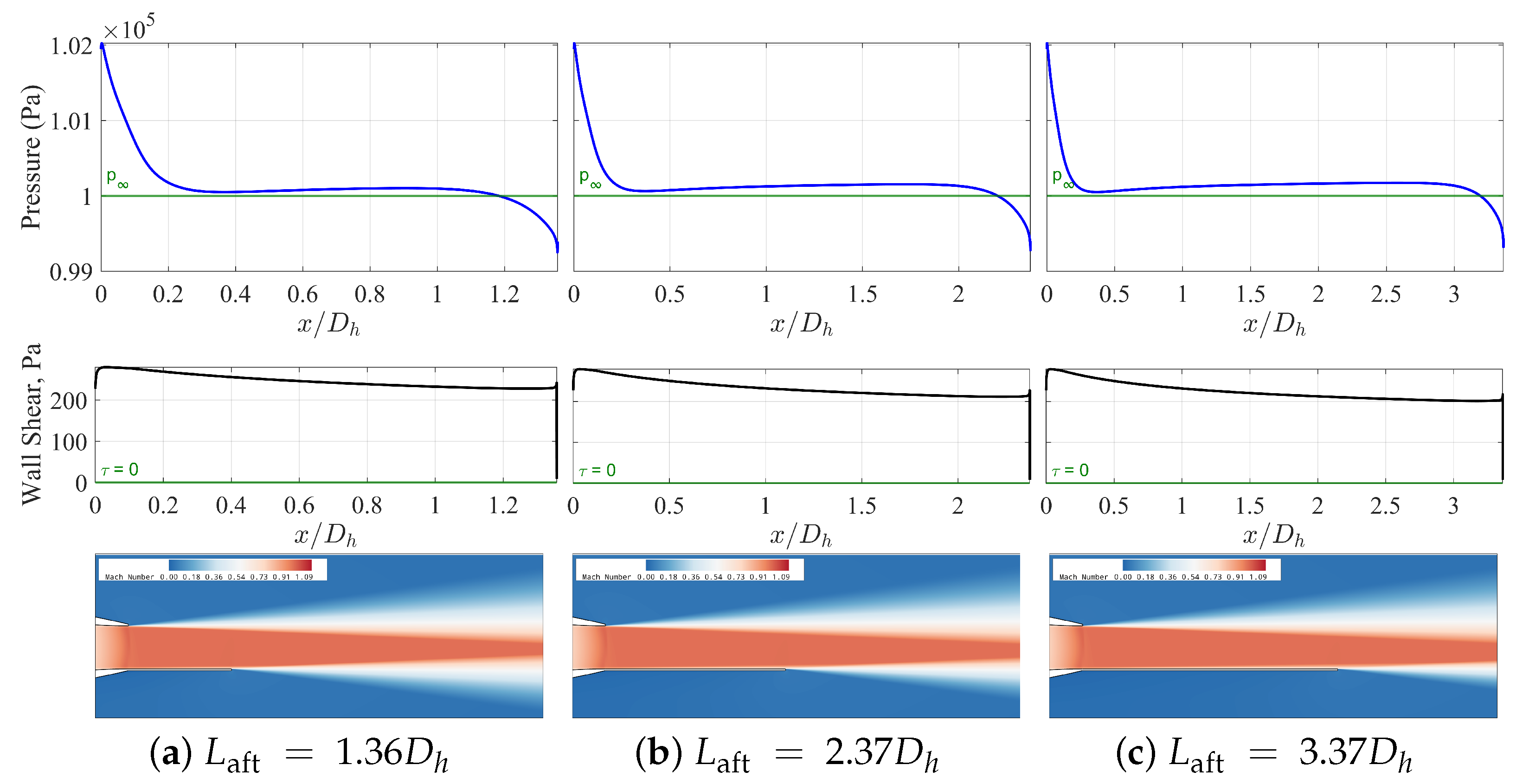
At the lowest NPR of 1.9 (
Figure 9), all three aft-deck configurations display similar flow behavior. The pressure distributions show consistent values along the entire aft-deck without significant oscillations that generate small upward forces (5–12 N) and negligible upward deflection angles (approximately 0.1°). The positive shear stress patterns indicate the absence of boundary layer separation, while the Mach contours reveal minimal shock structures. This consistency suggests that at low NPR values, expansion waves from the nozzle exit are too weak to generate significant pressure gradients or induce boundary layer separation. These observations align with the findings of Manikanta and Sridhar [
19], who reported similarly limited deflection effects at low NPR conditions.
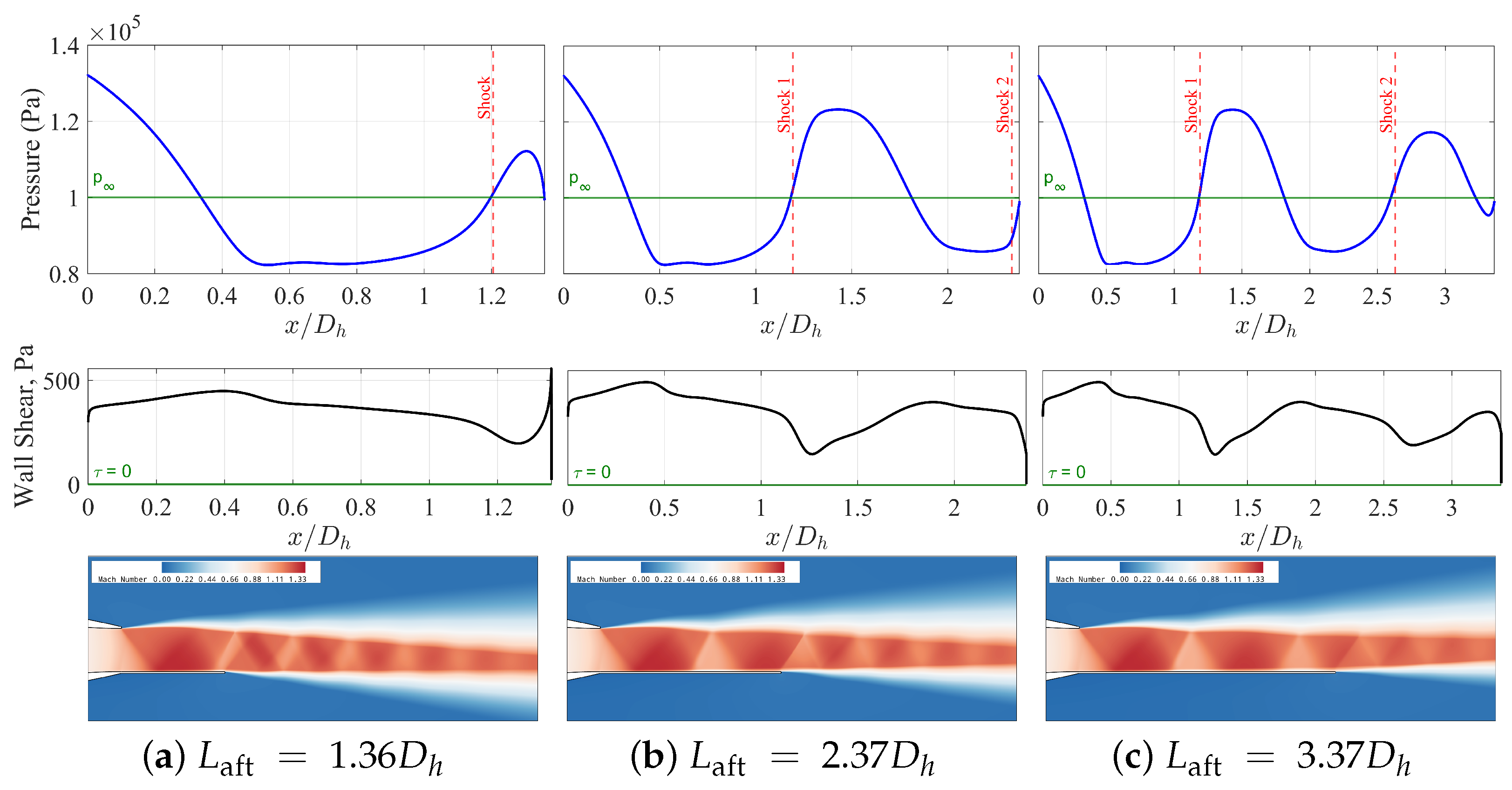
A significant transformation occurs at NPR = 2.5 (
Figure 10). Despite similar shock positions across all configurations (ranging from 1.19 to 1.21
from the nozzle exit), the resulting flow behavior varies considerably with aft-deck length. For the shortest configuration (
), the pressure distribution shows negative gauge pressure regions, generating downward forces and deflections (approximately −1.99° with a force of −98.5 N). As aft-deck length increases, the force behavior becomes irregular: some intermediate lengths exhibit positive forces, while others show negative forces. Despite these variations, the shear stress distributions indicate the boundary layer remains attached across all configurations at this NPR. This suggests that at moderate NPR values, the shock position relative to the aft-deck termination becomes a critical factor in determining deflection direction, even in the absence of boundary layer separation. The findings at this NPR align with observations of Kopriva et al. [
15], who reported similar variations in deflection direction with aft-deck length at comparable NPR values.
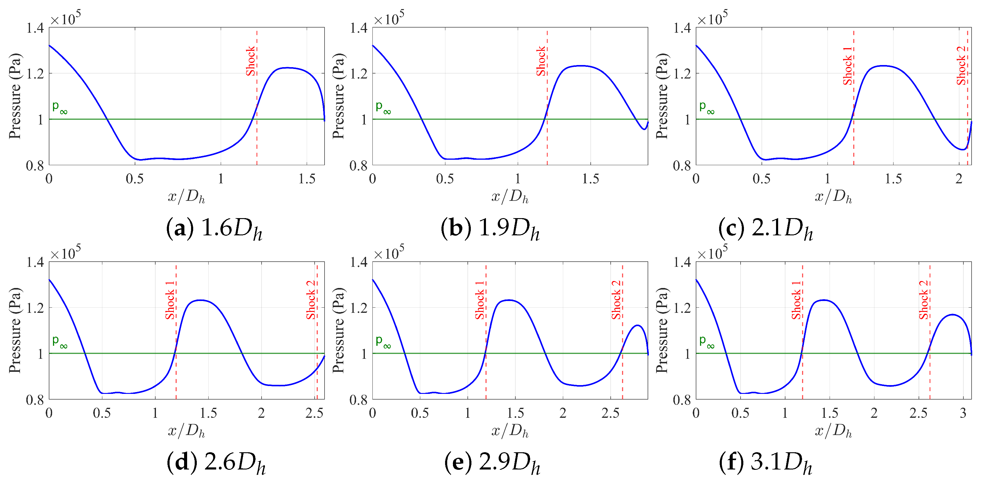
Figure 11 presents the rest of the parameter sweep across all nine aft-deck lengths at NPR = 2.5. The irregular variation in pressure distributions with aft-deck length suggests that the relationship between shock reflection patterns and aft-deck termination is highly sensitive to small changes in configuration.
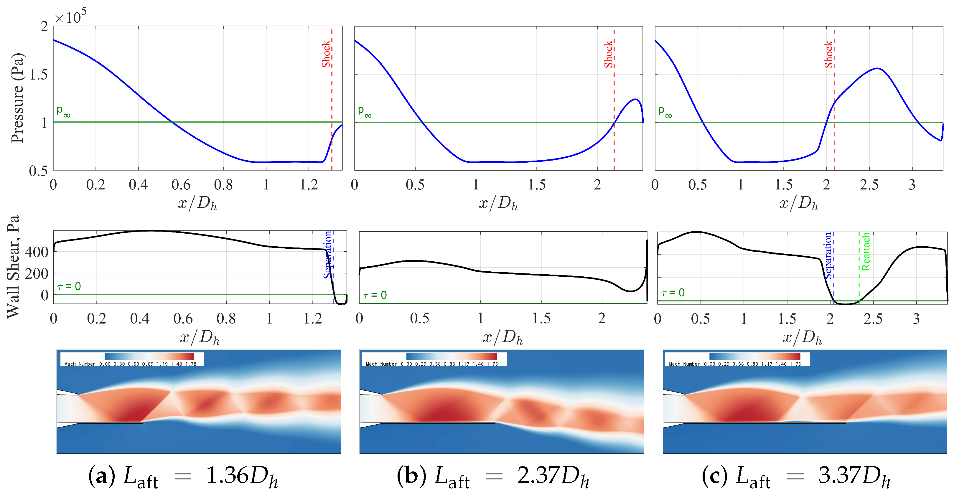
At NPR = 3.5 (
Figure 12), the complexity increases substantially. The shock positions now vary significantly with aft-deck length shifting from 1.31
for the shortest configuration to 2.14
for the intermediate and longest aft-decks. This marks a critical change from the previous NPR regime, where shock positions remained nearly constant across aft-deck lengths. The shortest configuration shows positive forces (41.2 N) and upward deflection (0.64°), while most intermediate lengths exhibit negative forces with substantial downward deflection. Notably, the shear stress distributions reveal the onset of boundary layer separation, occurring just downstream of the shock reflection in multiple configurations. This introduces a new mechanism that significantly influences the pressure distribution and resulting forces. The separation patterns align with the separation mechanisms identified by Nageswara and Kushari [
17], who observed similar behavior in elliptical nozzle configurations with aft-decks.
Figure 13 shows additional aft-deck lengths at NPR = 3.5 and reveals a more complex pattern of force variations that align with the flow reorganization patterns documented by Chen et al. [
21]. The variation in separation behavior with aft-deck length significantly affects pressure distributions and resulting deflection angles.
The highest NPR of 4.5 (
Figure 14) reveals a near-linear relationship between aft-deck length and shock position. The first shock reflection moves progressively downstream with increasing aft-deck length, from 1.28
to 2.98
. This systematic shift correlates with a reversal in flow behavior between the shortest and longer configurations. The shortest aft-deck develops a strong positive force (776.3 N) and substantial upward deflection (7.37°), while the intermediate and longest decks generate increasingly negative forces and downward deflection (reaching −10.52° for the
configuration). The shear stress patterns show pronounced separation regions near the aft-deck edge. This NPR regime demonstrates the strongest coupling between shock position, boundary layer separation, and resulting deflection behavior. The findings extend the NPR-dependent trends observed by Manikanta and Sridhar [
19] to higher pressure ratios.
The irregular behavior observed for
warranted detailed investigation at intermediate
values.
Figure 15 examines four critical points (
and
) that bracket multiple sign reversals. The progression confirms a highly non-monotonic relationship between
and deflection for the intermediate aft-deck length as
increases from 2.25 to 5.0. The shock position evolves systematically with
but the deflection response exhibits complex, bifurcation-like behavior that cannot be predicted from shock position alone and extends beyond the single-reversal patterns documented in previous studies [
19,
21].
In
Figure 8, multiple sign reversals of the deflection angle occur only within a few confined regions along the
axis. Specifically, at
, the sign switches twice between
; at
, between
; at
, between
; and at
, three closely spaced reversals appear within
. A borderline case is also observed at
over
. These overlapping intervals form a continuous narrow band centered around
for
, which constitutes the primary multi-switch region where the deflection direction reverses more than once within a small change of the control parameters.
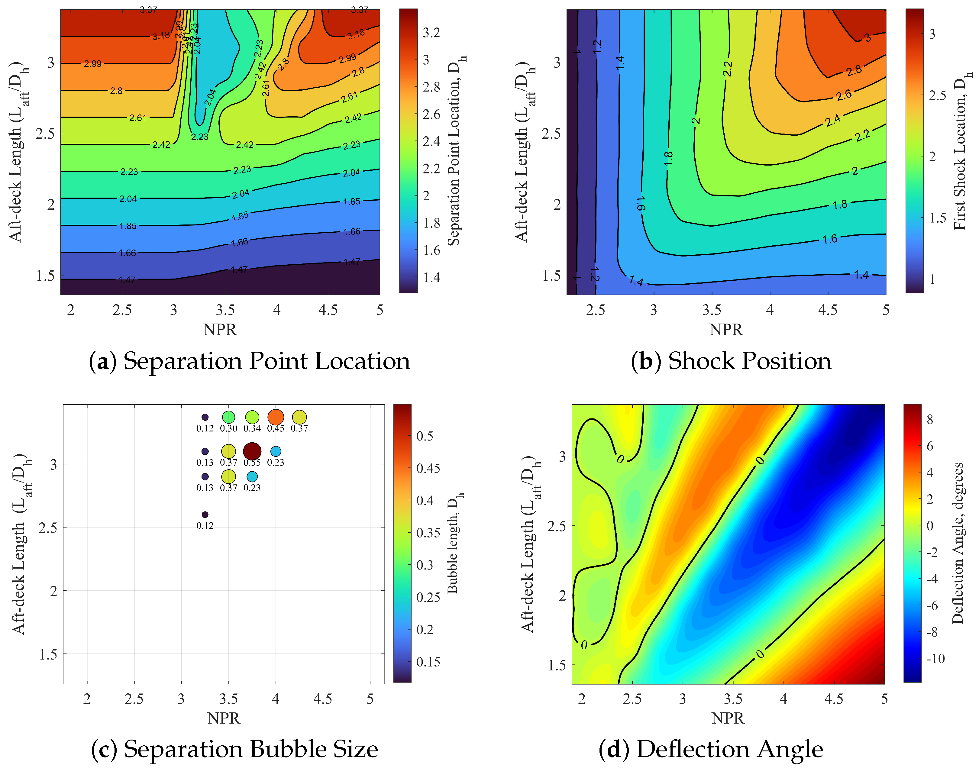
Figure 16 presents a side-by-side comparison of separation point location, shock position, separation bubble size, and deflection angle across the parameter space. The separation bubble data reveals that closed recirculation regions are limited to a narrow range of the parameter space, specifically
and
, encompassing only 13 of the 117 configurations. This localized separation bubble region corresponds to an area of significant upward deflection in the deflection map. This suggests that boundary layer separation, followed by reattachment, may serve as a secondary mechanism that enhances deflection behavior when it occurs.
From this analysis, we can identify several possible key mechanisms driving deflection behavior. The position of the first shock reflection relative to the aft-deck termination appears to be the primary determinant of deflection direction across most of the parameter space. When shocks reflect near the aft-deck edge, they generate asymmetric pressure distributions that drive deflection. Boundary layer separation serves as a secondary mechanism that modifies pressure distributions and amplifies deflection behavior when present. The separation onset is closely related to shock impingement location and strength. Additionally, the pressure recovery pattern following shock reflection varies with NPR and aft-deck length, creating complex pressure distribution patterns that influence net force direction.
The above qualitative analysis reveals that jet deflection in rectangular supersonic jets with aft-decks results from a complex interaction of inviscid shock dynamics and viscous boundary layer effects. At low NPR values (≈1.9), shock structures are weak and boundary layers remain attached regardless of aft-deck length. The resulting pressure distributions are nearly uniform, producing minimal deflection. As NPR increases to moderate values (≈2.5), shock structures strengthen while boundary layers generally remain attached. The deflection direction is primarily determined by the relationship between shock reflection position and aft-deck termination, leading to irregular behavior with aft-deck length. At higher NPR values (≈3.5–4.5), strong shock–boundary-layer interactions lead to separation in specific configurations. The separation modifies pressure distributions, creating complex deflection patterns that cannot be predicted from shock position alone.
This physical model extends previous theories by recognizing the hierarchical and competitive nature of multiple deflection mechanisms. Rather than a simple monotonic relationship, deflection behavior results from the dynamic balance between shock position effects, boundary layer response, and pressure recovery characteristics—each dominating under different parameter combinations. The bifurcation-like behavior observed in the configuration suggests that jet deflection in these systems can be understood through the framework of nonlinear dynamics, where multiple stable states exist and transitions between states occur at critical parameter values.
6. Conclusions
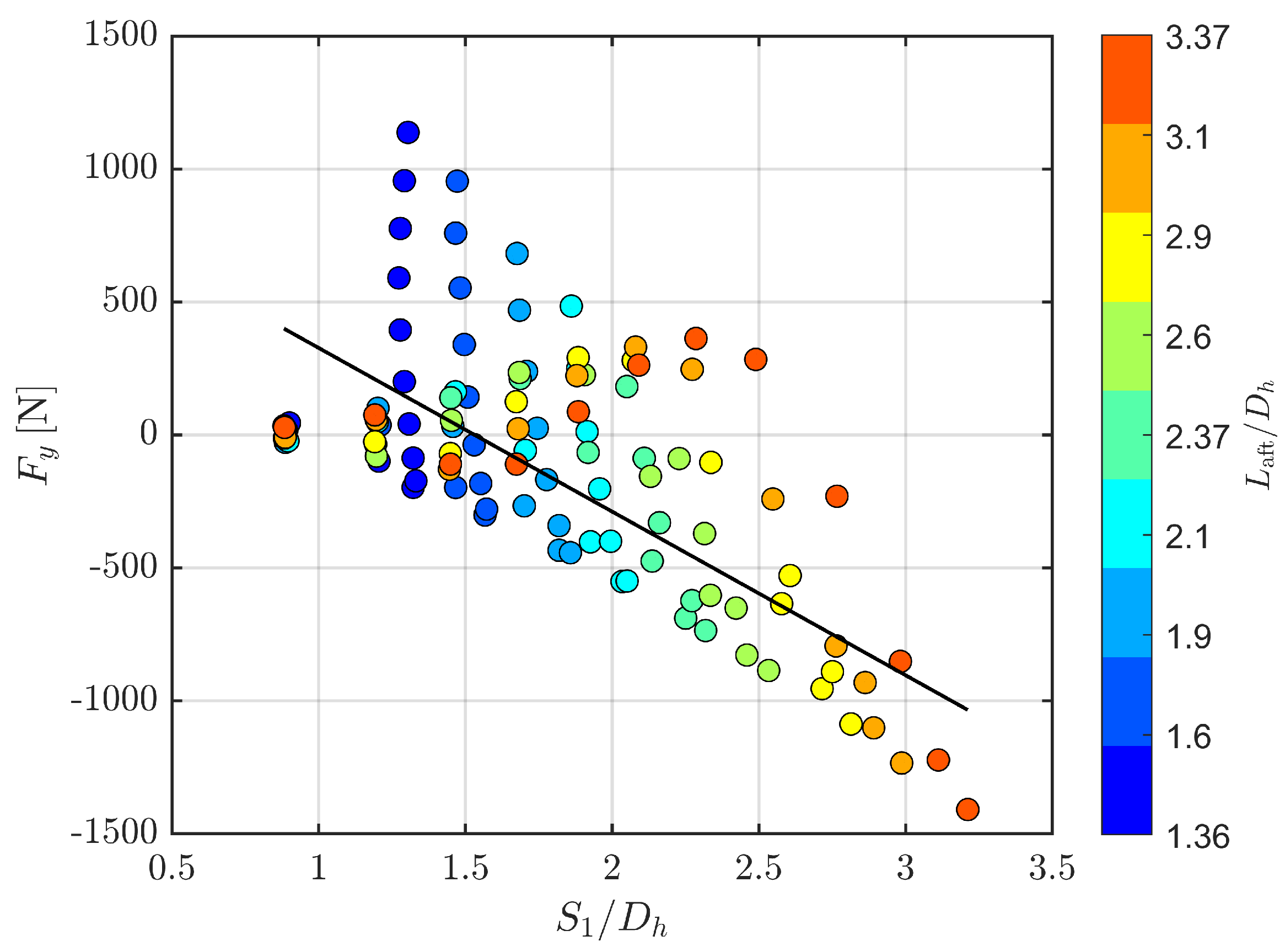
This study presents a comprehensive investigation of plume deflection mechanisms in underexpanded supersonic rectangular jets with aft-decks. The objective is to establish a unified physical model and to resolve the uncertainty arising from contradictory experimental observations. To achieve this objective, a systematically designed database of 117 Reynolds-averaged Navier–Stokes simulations was assembled, covering nozzle pressure ratios from 1.9 to 5.0 and aft-deck lengths from 1.36 to 3.37 hydraulic diameters. Each configuration was post-processed to extract the first shock reflection point, the surface-pressure field, the deck-integrated vertical force, and the resulting jet plume angle, thereby allowing every link in the proposed causal pathway to be examined in isolation.
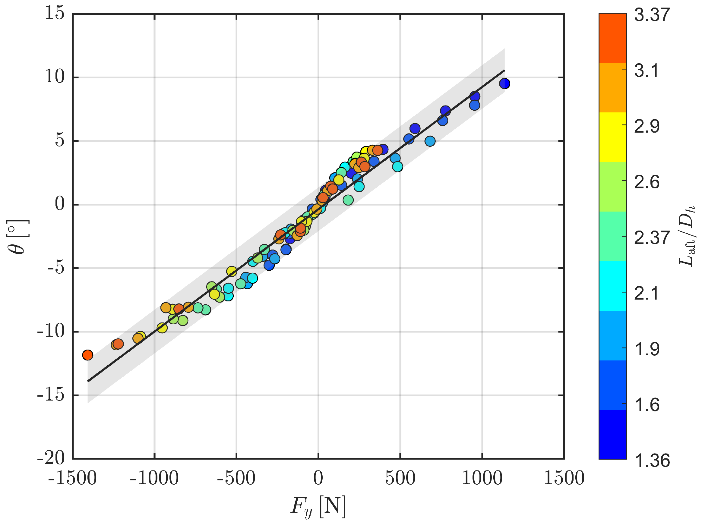
The analysis confirms that nozzle pressure ratio and aft-deck length jointly determine the location of the first oblique-shock reflection, and that location reshapes the wall-pressure distribution, and the integrated pressure imbalance fixes both the sign and the magnitude of the deflection angle. Three operating windows emerge from the data. When the reflection strikes near the deck lip, the local pressure deficit remains negative and the jet plume turns steadily downward. When longer decks and higher pressure ratios displace the reflection upstream, a shock–boundary-layer interaction forms a closed separation bubble, inverts the pressure gradient, and lifts the jet plume by as much as eight degrees. Between these extremes, a narrow band exists in which modest variations in either control variable decide whether the jet plume deflects upward or downward, thereby explaining the direction reversals that appear scattered in the experimental record. A weighted multi-block regression that preserves this sequence yields for the – relation, while the upstream blocks achieve (for ) and (for ). The overall root-mean-square error in is approximately 1°, and the linearized chain implies aggregate sensitivities of roughly −2.7° per unit NPR and −2.8° per unit .
The primary objective of the study was achieved, and the previously conflicting experimental trends are placed within a coherent framework. However, the mechanism’s predictive power is bounded by a number of modelling constraints and the results and conclusions of this study should be interpreted in view of these limitations. First, the flow is computed in two dimensions, so spanwise mixing and tip-vortex development are absent; consequently, the far-field decay of deflection is slower than in fully three-dimensional measurements. Second, the simulations are steady. Low-frequency oscillations of the separation bubble and the intermittent motion of the shock system are therefore averaged out. Third, the weighted regression trades a small amount of absolute accuracy to retain the link between each causal block. Fourth, the second-order upwind scheme introduces numerical dissipation that affects the resolution of critical flow features. For shock waves, this artificial diffusion smears the discontinuity across multiple grid cells, reducing shock strength. In shear layers, the numerical dissipation thickens the shear layers and accelerates their growth rate. Within these limits, the mechanism still offers a robust qualitative narrative and a dependable first-order guide for jet plume steering over the entire parameter range investigated.
Future work should employ three-dimensional simulations to capture the complex flow patterns over the aft-deck and to resolve 3D spanwise mixing. To provide a more complete picture, the parameter space should also be expanded to include the nozzle-exit aspect ratio, deck-bevel angle, and the presence of aft-deck sidewalls.
