Article

Design, Roll Control Evaluation and Flight Test of Inflatable-Winged UAVs in Two Configurations

1
Department of Mechanical, Materials and Manufacturing Engineering, Faculty of Science and Engineering, University of Nottingham Ningbo China, Ningbo 315100, China
2
Ningbo Institute of Materials Technology and Engineering, Chinese Academy of Sciences, Ningbo 315100, China
*
Author to whom correspondence should be addressed.
Aerospace 2025, 12(11), 976; https://doi.org/10.3390/aerospace12110976 (registering DOI)
Submission received: 20 September 2025 / Revised: 22 October 2025 / Accepted: 28 October 2025 / Published: 30 October 2025
(This article belongs to the Section Aeronautics)

Abstract

In this research, two inflatable-winged Unmanned Aerial Vehicles (UAVs) in distinct configurations, a single-fuselage layout with external trailing-edge control surfaces and a twin-fuselage layout with fully movable control surfaces were designed, developed, and flight tested to investigate the flight characteristics of inflatable-winged aircraft. Initially, inflatable wings were designed and fabricated from various materials, followed by rigorous ground testing, including structural characteristics tests, pressure retention and resistance tests, and low-speed wind-tunnel evaluations. Following this, two methods for controlling the inflatable wings were proposed, and their roll control effectiveness was thoroughly investigated. Subsequently, two inflatable-winged UAV prototypes, each employing a different configuration and manipulation method, were designed, assembled, and subjected to basic low-altitude flight tests to assess the feasibility of their aerodynamic layouts and control characteristics. The results demonstrated that a segmented wing design with a multi-boom configuration is particularly well-suited for inflatable wings. Additionally, both proposed control methods were tested and shown to be effective in flight. The findings provide valuable insights into the properties of inflatable wings and offer substantial guidance for the development of inflatable-winged aircraft.

1. Introduction

Inflatable wings have gained significant attention in aerospace applications in recent decades thanks to their superior storage efficiency, impact resilience, and lightweight characteristics. The transformation from rigid to inflatable wing structures dates back to the 1930s, with successful flight demonstrations such as the Goodyear Aerospace GA-33 and GA-466 Inflatoplanes [1,2]. Advancements continued in the 1970s with ILC Dover’s Apteron Unmanned Aerial Vehicle (UAV), a flying-wing design featuring wings fully retractable into the fuselage, showcasing exceptional stowage capabilities [3]. Progress in materials and manufacturing technologies has since accelerated the development of modern inflatable-winged UAVs [4]. These compact and transportable systems enable versatile airborne deployment—including launches via catapults, aircraft, or balloons—highlighting their strong potential for emergency rescue operations and outer space exploration [5,6,7].
Considerable research has been conducted on inflatable wings, addressing various aspects such as aerodynamics, structure, load, and control. Cadogan et al. [4] and Wade and Rachel [8] provided overviews of inflatable technologies, including a review of inflatable wing designs and related technologies. In the context of aerodynamic properties, Lebeau et al. [9] performed numerical investigations on the impact of surface roughness on two distinct inflatable airfoil designs. Their study highlighted the dependence of airflow alterations on the underlying shape of the airfoil. Ghobadi et al. [10] expanded the research by conducting a comprehensive series of Particle Image Velocimetry measurements and Computational Fluid Dynamics (CFD) simulations. Their study focused on both bumpy and smooth variants of the NACA 4318 airfoil, offering valuable insights into the flow physics and aerodynamic performance of inflatable wings. Additionally, Beltz et al. [11] conducted a wide range of simulations and wind tunnel experiments, further advancing researchers’ understanding of the aerodynamics of inflatable wings.
For structural design and analysis, Breuer et al. [12] introduced the innovative concept of Tensairity, offering a novel approach to enhance the load-bearing ability of inflatable wings. Ma et al. [13] presented a new inflatable wing design featuring sweep-arranged inflatable beams, analyzing key design variables and methods to enhance structural performance and modal behaviors. Wei et al. [14] proposed a structural design for a bionic inflatable delta wing that features an outer flexible surface that can be stretched via interval inflatable beams, and conducted dynamic analysis to evaluate its performance. In a complementary study, Rakshith et al. [15] developed a comprehensive methodology for predicting the failure of inflatable wings through stress analysis. Mao et al. [16] investigated, via simulations and experiments, the load-bearing characteristics and failure evolution patterns of inflatable wings and quantitatively revealed a linear correlation between internal pressure and structural stability. Furthermore, Cadogan et al. [17] showcased the impact, survivability, and reusability of inflatable wings through laboratory and flight testing.
In exploring the aeroelastic characteristics of inflatable wings, Butt et al. [18] proposed an innovative inflatable wing extension, which can be compactly packed into a rigid section. Meanwhile, Simpson et al. [19] conducted wind tunnel tests to scrutinize the behaviors of inflatable wings under varying dynamic pressure. Furthermore, Rendall et al. [20] demonstrated via wind tunnel experiments that the dynamics of small inflatable wings are predominantly influenced by lock-on (vortex shedding) and flow-induced vibrations.
Regarding control and flight dynamics of inflatable-winged UAVs, Cadogan et al. [17] examined the control effectiveness of utilizing Shape Memory Alloys (SMAs) for morphing wings and servo-actuator wings through both wind tunnel testing and flight experiments. Additionally, Simpson and Jacob [21,22] explored a new roll control method utilizing wing warping and demonstrated its efficacy through flight tests. This mechanical manipulation of wing shape proved effective in achieving roll control.
Meanwhile, several studies have focused on the optimization of inflatable wings. By accurately identifying the effects of pressure, load, and chamber count on the bending response and product quality, Wang and Wang [23] proposed an optimization scheme using orthogonal testing and support vector machines for inflatable wings. Employing an improved non-dominated sorting genetic algorithm to balance section difference and mass minimization, Shi and Wang [24] introduced a multi-objective optimization design for inflatable airfoil structures intended for flying-wing buoyancy-lifting UAVs. In the field of multidisciplinary coupled cross-domain optimization, Ma et al. [25] constructed a high-precision model to investigate the thermal-fluid-structure coupling analysis during the cross-domain flight of inflatable wings.
In summary, existing research on inflatable wings has significantly enhanced our understanding of their characteristics. However, due to the limitations by current materials and manufacturing processes, the load-bearing capability of inflatable wings remains substantially lower than conventional rigid structures. Currently, most inflatable-winged aircraft utilize a conventional cantilevered monoplane configuration with a low aspect ratio wing, see in [3,5,6,7,17]. There is a notable gap in research focused on developing a suitable configuration and conducting comparative analyses that consider the ”low load-bearing” property of inflatable wings.
Additionally, regarding the control of inflatable-winged UAVs, some studies have not incorporated any control methods on the inflatable wings themselves. Instead, these UAVs achieve overall control by adding larger control surfaces to the tail, which employs conventional rigid structures, see [3,5,6,7]. This approach inevitably leads to a reduction in the aircraft’s maneuverability and complicates effective control. In contrast, other studies have achieved inflatable wing manipulation through wing warping which is proven to be effective [17,21,22]. However, practical observations indicate that maintaining the load-bearing characteristics of inflatable wings requires high internal inflation pressure. As a result, substantial torsional stiffness develops along the chord-wise direction of the wing, posing challenges for controlling deformation using lightweight servo actuators or SMAs. This creates an inherent trade-off between the load-bearing capabilities and the controllability of the inflatable wing when employing this control method, as the inflation pressure directly influences wing loading. This trade-off is a key factor limiting the size of inflatable-winged UAVs utilizing this control approach. These UAVs typically weigh only a few kilograms, with reduced wing loading to minimize internal pressure requirements. Therefore, there is also an urgent need to explore innovative and effective control methods for inflatable wings.
In this work, a comparative study is presented on two distinct inflatable-winged UAV configurations, each employing different manipulation methods: a single-fuselage layout with external trailing-edge control surfaces and a twin-fuselage layout with fully movable control surfaces. The study was conducted through rigorous flight tests and aims to explore suitable configurations for UAVs with inflatable wings, especially those with high aspect ratios. Additionally, it investigates the feasibility and effectiveness of the two novel manipulation methods for inflatable wings.

2. Design and Ground Tests of Inflatable Wing

2.1. Inflatable Wing Design

Several inflatable wing design methodologies have been explored in previous research, including the use of inflated tubes with varying diameters, covered by tensioned skins, and sometimes supported by foam beneath the skin [4]. This current study focuses on a multi-spar approach, utilizing multiple chambers or inner-inscribed circles to approximate the aerodynamic shape of a conventional wing. The structure of the inflatable wing is illustrated in Figure 1. The designed inflatable wing consists of 14 chambers, which are interconnected at the wingtips to ensure uniform internal pressure. Internal spars are strategically placed at the intersections of two adjacent inscribed circles to maintain the aerodynamic shape after inflation.
The inflatable wing is constructed using high-strength fabrics combined with thermally activated adhesive bonding techniques. A variety of materials, including Kevlar, Nylon, and Vectran fabrics, were employed and tested in this study. All materials feature a three-layer sandwich structure, with the core material (the fabric) providing the load-bearing capability, while the inner and outer polyurethane coatings serve to prevent air leakage and maintain the internal pressure. Additionally, each inflatable wing is equipped with manually operated inflation valves, which allow for precise control and monitoring of the inflation pressure, as well as the inflation and deflation of high-pressure gas.

2.2. Ground Tests of Inflatable Wing

A comprehensive evaluation of the mechanical and aerodynamic characteristics of the inflatable wing was conducted through a series of simulations and ground tests. The experimental campaign encompassed load-bearing tests, low-speed wind tunnel experiments, pressure retention and resistance evaluations, and folding tests.

2.2.1. Load Tests

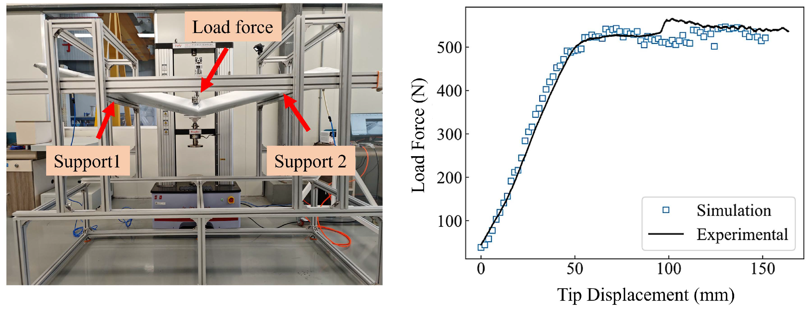
For the load-bearing tests, a 3-m standard wing section was evaluated under different inflation pressures to examine its structural performance. The tests were conducted by gradually increasing the applied load while measuring the corresponding tip deflection and identifying the failure mechanisms of the inflatable wing structure. The experimental setup, along with a comparison between the simulated and measured force–displacement curves at an inflation pressure of 70 kPa, is shown in Figure 2. The simulations were conducted using the commercial finite element method (FEM) software Abaqus® 2021.
The results demonstrate that, compared with conventional rigid wings, inflatable wings exhibit better structural resilience. In particular, inflatable wings are less susceptible to permanent damage under transient overloads. Furthermore, even beyond the critical load, the flexible inflatable structure can retain a high load-bearing capability. As illustrated in the figure, the simulation results show good agreement with the experimental measurements, validating the accuracy of the numerical model. This validated simulation methodology offers valuable guidance for the prototype aircraft design, particularly in selecting key parameters such as wing loading and inflation pressure. Additional details regarding the test methodologies, materials tested, and corresponding results are provided in [16].

2.2.2. Wind Tunnel Tests

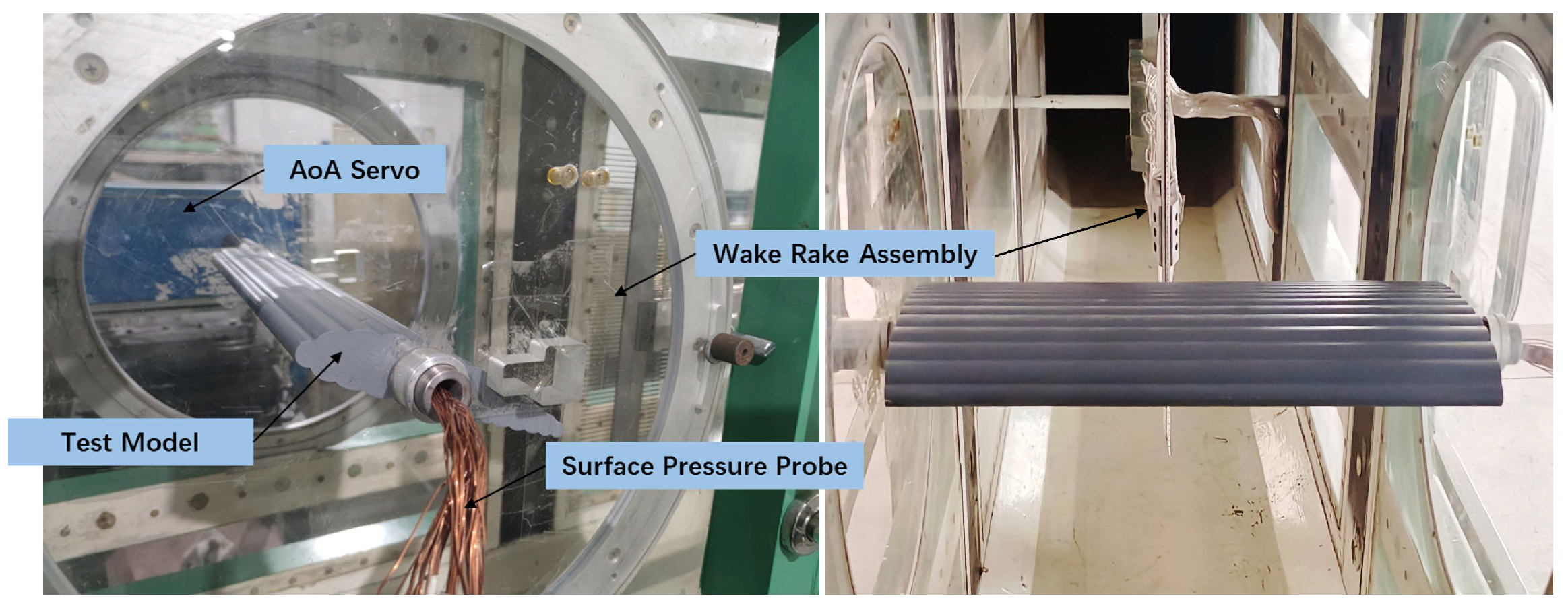
To investigate the influence of surface undulations on the aerodynamic performance of inflatable wings, a series of tests were carried out in a low speed wind tunnel. The Reynolds number ( R e ) of the experiments ranged from 1.0 × 10 5 to 7.0 × 10 5 , essentially covering the flight profile of a typical inflatable-winged UAV. The wind-tunnel experiments were conducted using a one-third scaled 3D-printed model and covered angles of attack from −4 to 22 °C. The experimental setup is illustrated in Figure 3.
The results demonstrate that, aerodynamically, the inflatable wings show enhanced performance, particularly at higher angles of attack, and exhibit improved stall properties, characterized by a smooth transition into the post-stall region without a sudden drop in lift coefficient. The wind tunnel results also serve to refine and validate the CFD simulation methods, providing strong support for the aerodynamic configuration design of subsequent prototype aircraft. Additional details regarding the test methodologies and corresponding results are provided in [26].

2.2.3. Pressure Retention and Resistance Tests

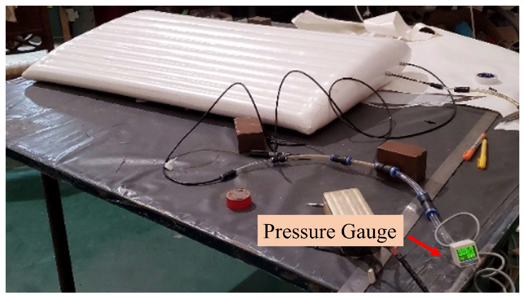
Regarding pressure retention capability, the wing was inflated to the design operating pressure of approximately 70 kPa (as determined by the load-bearing requirements). The internal pressure was then continuously monitored over time, as shown in Figure 4. The test results indicate that under the design pressure, the internal pressure decreased by approximately 5 kPa after 1 h, corresponding to a 7% reduction. This pressure loss is likely attributed to minor leakage caused by the welding process, valve imperfections, or intrinsic material permeability. Nevertheless, since the target demonstration mission requires only about 1 h of flight time (see in Section 4.1), and the initial inflation pressure of 90 kPa provides a sufficient safety margin above the design pressure, the inflatable wing demonstrates adequate pressure retention performance to meet the mission requirements.
Additionally, a pressure resistance (burst) test was conducted to determine the structural limit of the inflatable wing. The results confirmed that the wing can withstand a maximum internal pressure of approximately 130 kPa, which is significantly higher than the rated operating pressure of 70 kPa.
These tests provide valuable insights into the pressure-retention and resistance characteristics of inflatable wings under current material and manufacturing constraints, offering practical guidance for determining appropriate inflation pressure in the subsequent prototype aircraft designs. Furthermore, based on the test data, Vectran fabric outperformed alternative materials in both load-bearing, pressure retention and resistance capabilities, leading to its selection as the primary material for the wing.

2.2.4. Foldability Test

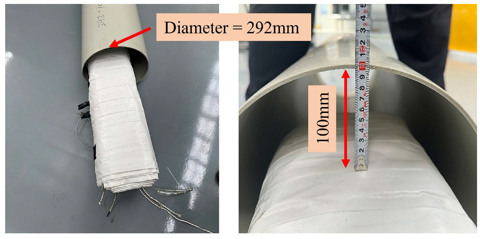
The foldability test demonstrated that a 6-m-span inflatable wing can be compactly folded into a package with a diameter of approximately 200 mm, as shown in Figure 5, highlighting its excellent storage capability.
In summary, the ground test results demonstrated that the inflatable wings exhibit superior structural stability and significantly higher foldability compared to conventional rigid wings. Aerodynamically, the inflatable wings showed enhanced performance at higher angles of attack. The results confirmed the feasibility of implementing inflatable wings on aircraft and provided critical experimental data to support the development of subsequent prototypes.

3. Roll Control of Inflatable Wing

Ensuring adequate control effectiveness is critical for the UAV’s flying quality and efficient mission completion. In this context, roll control effectiveness is a fundamental maneuverability parameter. Here in this study, roll control is analyzed as an example to assess the effectiveness of the two novel manipulation methods for inflatable wings.

3.1. Roll-Control Requirements

According to existing flight quality standards for manned and unmanned aircraft, the roll control effectiveness is typically measured by the minimum time required to achieve a targeted bank angle ( Φ t ) during specific flight phases [27,28,29]. Current standards categorize UAVs into various levels based on factors such as size, weight, and mission type, and for each level there are distinct flight performance requirements [30]. Considering the flight and operational characteristics of the inflatable-winged UAVs in this study—primarily used for the purpose of communication relay without significant maneuvering demands—the following roll control effectiveness criteria are defined:
  • Level 1: Φ t = 60 °C in 1.7 s; flying qualities are clearly adequate to accomplish the mission’s flight phases.
  • Level 2: Φ t = 60 °C in 2.5 s; flying qualities remain adequate to perform the mission’s flight phases with moderate degradation in mission effectiveness.
  • Level 3: Φ t = 60 °C in 3.4 s; degraded flying qualities remain adequate to stabilize the vehicle.

3.2. Roll-Control Principles

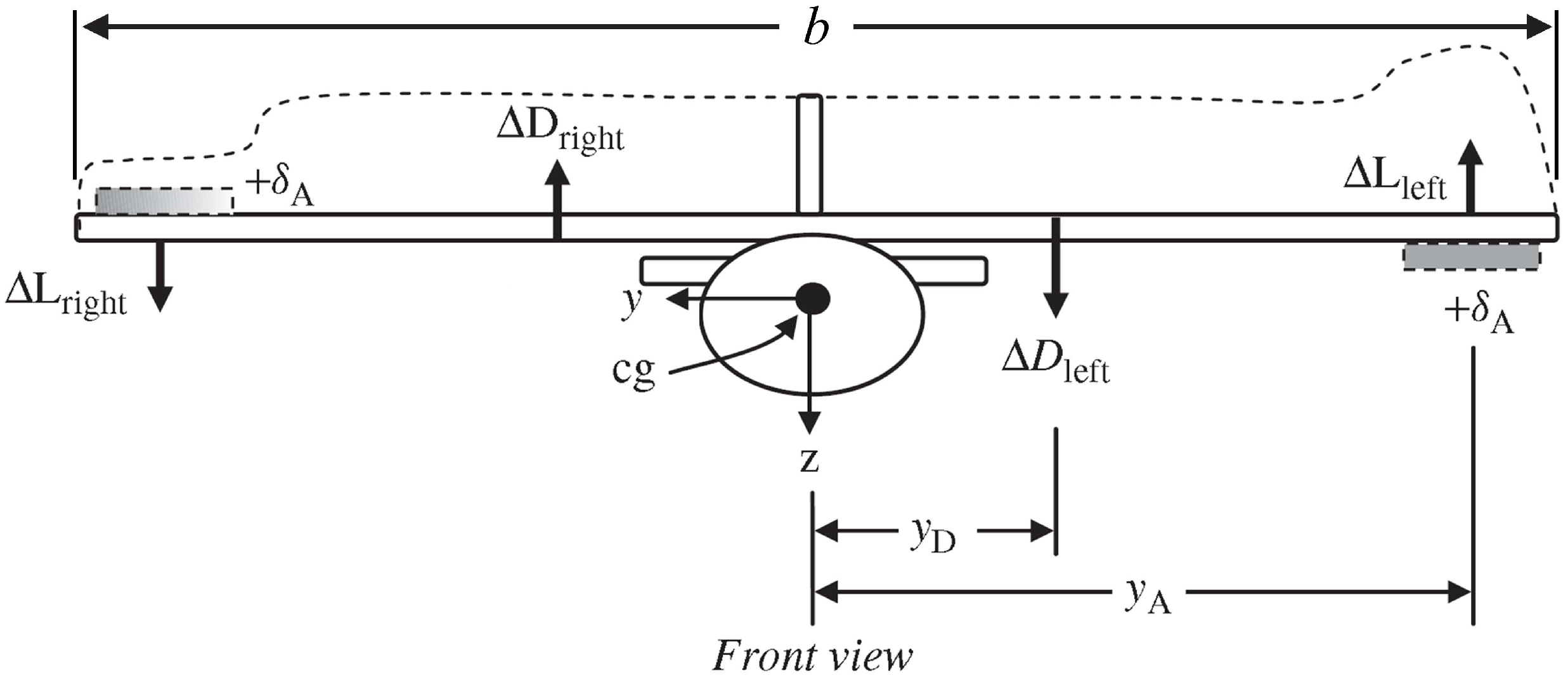
According to Newton’s second law for rotational motion, the sum of all external moments acting on a body is equal to the time rate of change of its angular momentum. In the context of roll control for an aircraft, the rolling moment is primarily generated by two sources: (i) the lift difference produced by aileron deflection and (ii) the aerodynamic rolling drag/damping resulting from the angular motion in the y z -plane. These forces act at distances from the aircraft’s longitudinal axis, thereby producing a resultant rolling moment. Figure 6 presents a front-view schematic of the aircraft, illustrating the incremental lift ( Δ L ) generated by the ailerons and the incremental drag force ( Δ D ) induced by the rolling motion [31]. The parameter y A denotes the average lateral distance between the ailerons and the roll axis (assumed to be aligned with the x-axis), while y D represents the average lateral distance between the acting point of rolling drag and the roll axis.
Based on these considerations, the total rolling moment M x acting about the longitudinal axis can be expressed as the sum of the contributions from both the aileron deflection and the roll damping effect. This moment is equal to the aircraft moment of inertia about the x-axis ( I x ) multiplied by the time rate of change of the roll rate ( p ˙ ):
M x = 2 Δ L · y A 2 Δ D · y D = I x p ˙ .
According to the definition of the aerodynamic rolling moment L A , which is generally modeled as a function of the wing area (S), wing span (b), and dynamic pressure ( q ¯ ) as:
L A = 2 Δ L · y A 2 Δ D · y D = q ¯ S C l b ,
where C l is the rolling moment coefficient. In a symmetric aircraft with no sideslip and no rudder deflection, this coefficient is modeled as:
C l = C l δ A δ A + C l p p ¯ ,
where C l δ A is referred to as the aircraft rolling moment coefficient due to aileron deflection and is also called the aileron roll control power, C l p is called the roll damping of the aircraft, which represents the anti-rolling moment induced by the rolling speed, and p ¯ is the non-dimensional roll rate defined by
p ¯ = p b 2 V .
Substituting Equations (2)–(4) into Equation (1) yields:
I x p ˙ = q ¯ S b ( C l δ A δ A + C l p p b 2 V ) .
Rewriting Equation (5) gives:
I x q ¯ S b p ˙ C l p b 2 V p = C l δ A δ A .
Taking the aileron roll control moment ( C l δ A δ A ) as the control input allows the analysis of the roll rate (p) response. The bank angle ( Φ ) resulting from rolling motion is defined by the integral:
Φ = p d t + Φ 0 .
Consequently, the bank angle response can also be determined.

3.3. Manipulation of Inflatable Wing

The manipulation of inflatable-winged UAVs is a critical issue addressed in this study. Based on existing research, the control of inflatable wings typically involves wing warping, achieved by altering the wing’s curvature. This method has been proven effective [17,21,32]. However, in practice, the load-bearing requirement of the inflatable wings demands a high internal inflation pressure. As a result, there is significant torsional stiffness along the chord-wise direction of the wing, making the deformation control very challenging using lightweight servo actuators. To address this problem, this study proposes and tests two innovative manipulation approaches, both of which demonstrate effective control performance and can be easily implemented using typical servos.

3.3.1. External Trailing-Edge Control Surfaces

The first approach involves adding external control surfaces, which are also inflatable and connected to the main wing via internal pipes to equalize the pressure. The connection between the control surfaces and the main wing is achieved through heat-pressed fiber cloth, ensuring both connection strength and freedom of deflection. The configuration is illustrated in Figure 7.
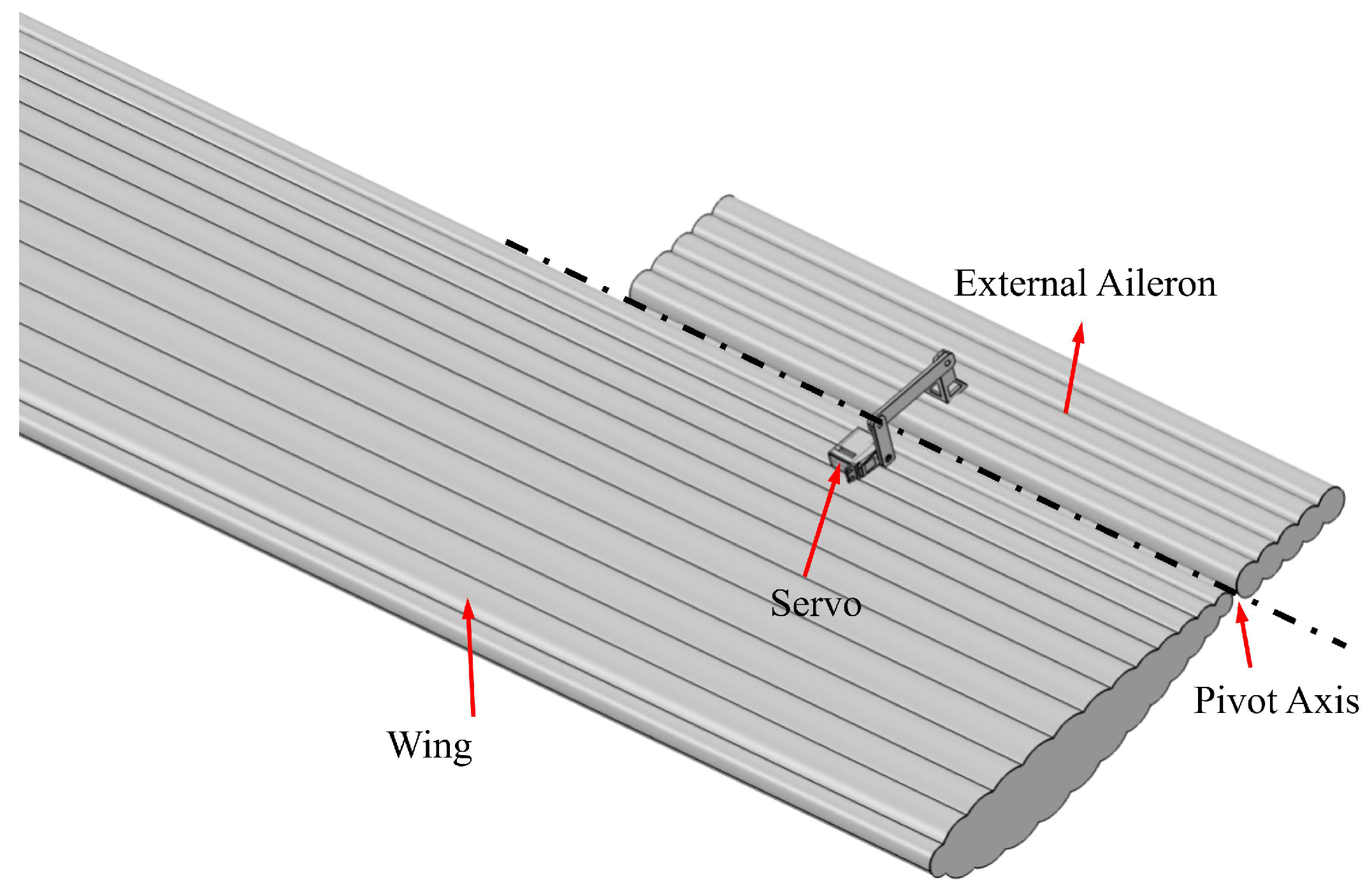
The detailed actuation mechanism for the external aileron is illustrated in Figure 8. As shown, a conventional linkage mechanism is employed, in which the deflection of the servo actuator drives the deflection of the control surface. Unlike the wing-warping control approaches reported in previous studies (see in [17,21,32]), this configuration only needs to overcome the aerodynamic moment acting on the control surface, rather than counteracting the chord-wise torsional stiffness of the inflatable wing itself, which can be significant at high inflation pressures. Consequently, this control configuration operates independently of the internal inflation pressure of the wing and can be readily implemented using typical servo actuators.
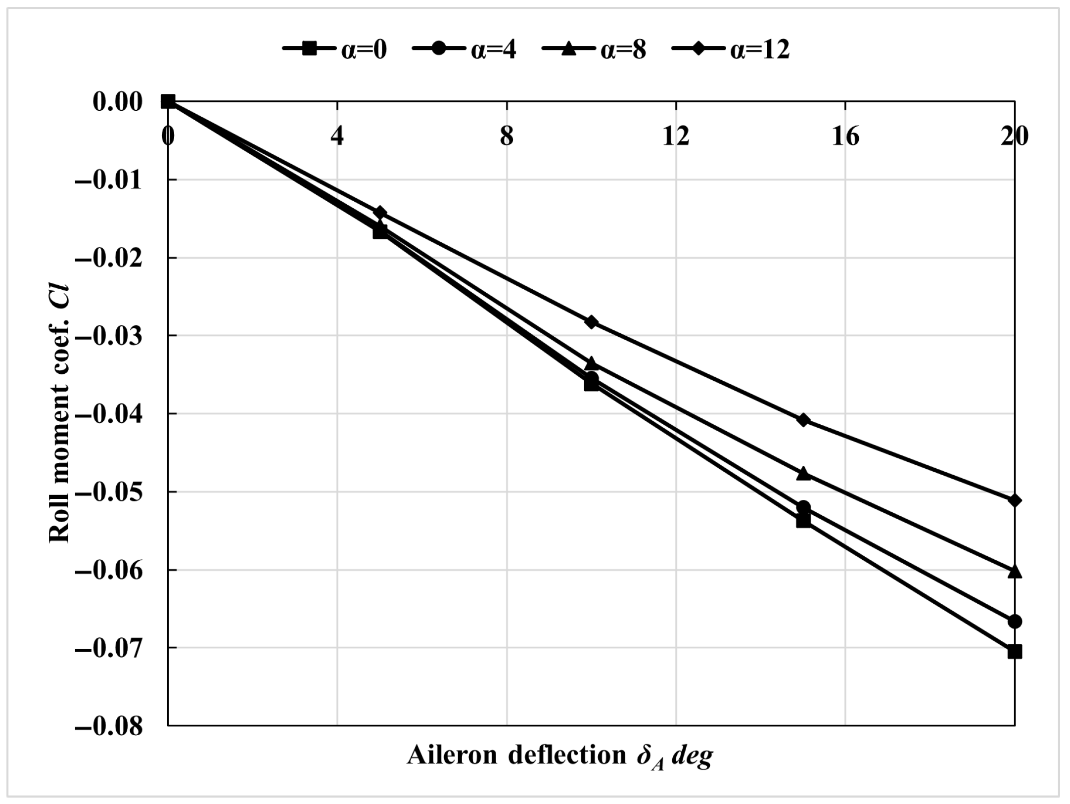
These external control surfaces can replace all the conventional control surfaces, including ailerons, elevators, and rudders. Figure 9 presents the estimated roll control effectiveness across a range of angles of attack, as determined through computational methods. The results demonstrate that deflection of the external inflatable ailerons generates significant roll control moments. The control effectiveness of the external inflatable ailerons will be further evaluated through numerical simulations and flight tests in the following sections.

3.3.2. Fully Movable Control Surfaces

The second approach employs fully movable control surfaces, adjusting directly the incidence angle of the outer inflatable wing sections to achieve attitude control. For smaller tail wings, the fully movable design can be directly applied, as successfully used in highly maneuverable aircraft, such as fighters. For the main wing, however, due to its large span and primary load-bearing role, direct manipulation of the entire wing is challenging. Additionally, roll control requires the opposite deflection of the control surfaces. Therefore, this study introduces the concept of fully movable ailerons, as shown in Figure 10. In this design, the main wing is divided into three sections: the central section retains its primary load-bearing function and is fixed to the fuselage, while the outer wing sections are designed as fully movable surfaces. Roll control is achieved through the antisymmetric deflection of the outer wing sections on both sides.
The detailed actuation mechanism of the fully movable aileron is illustrated in Figure 11. As shown, unlike conventional linkage-based control systems, the fully movable aileron is actuated by a servo motor mounted near the trailing edge, which drives the trailing portion of the surface to move up or down, producing rotation about a pivot axis located near the aerodynamic center. By varying the effective angle of attack of the entire surface, corresponding lift changes are generated to produce control moments. Unlike the wing-warping control methods reported in previous studies, the pivot axis is strategically positioned near the aerodynamic center of the surface, ensuring that the required actuation torque remains small even when the entire surface is deflected. Furthermore, this control configuration is also independent of the internal inflation pressure of the wing and can be easily implemented using typical servos.
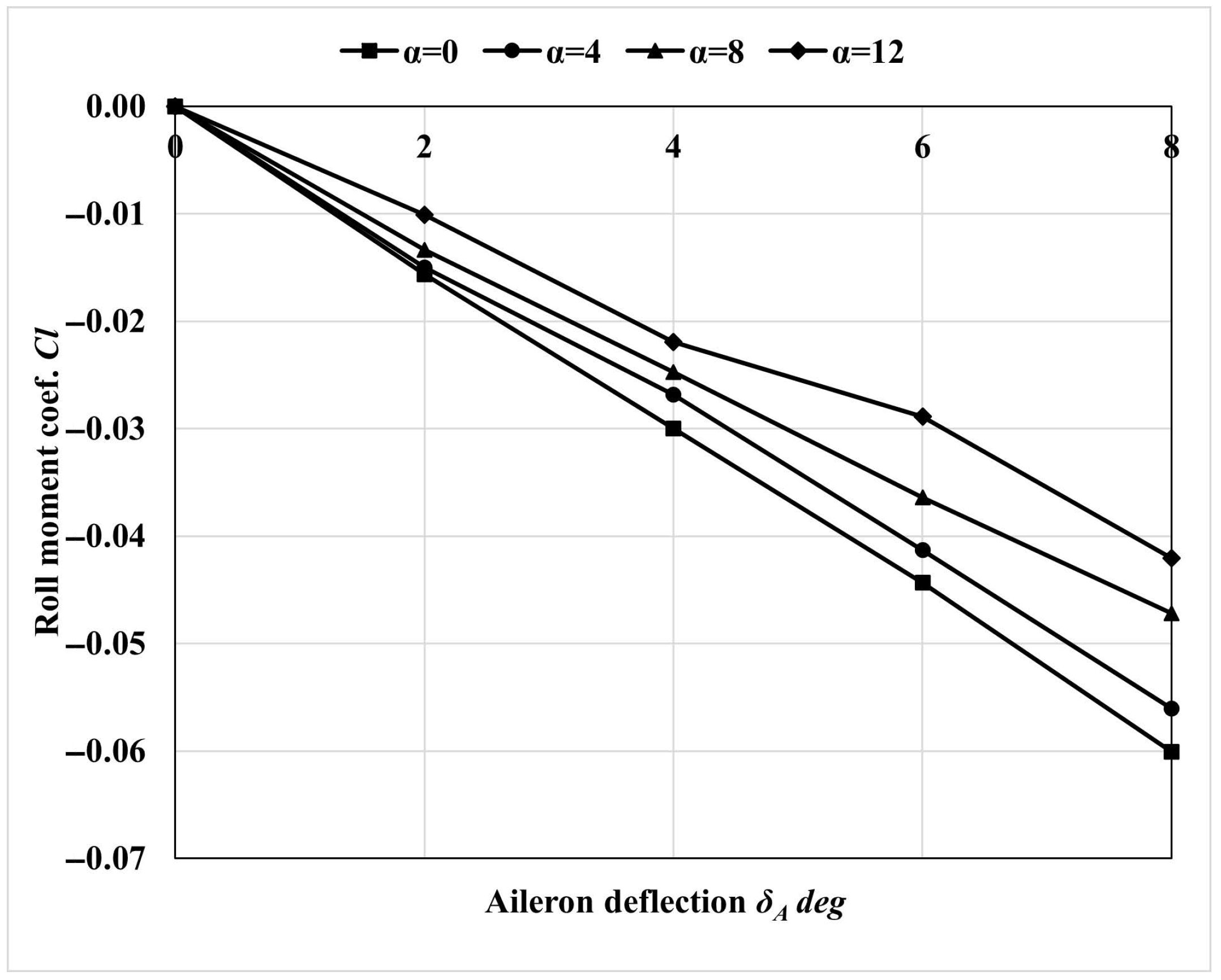
Unlike external ailerons, the fully movable ailerons achieve a maximum deflection angle of only 8 °C, yet even small deflections generate substantial control moments, as illustrated in Figure 12. Subsequent simulations and flight tests have confirmed the feasibility and effectiveness of this control method.
It is important to note that the deflection range of the fully movable ailerons must be carefully set, and a stall protection mechanism must be in place. This is because excessive positive deflection (increased angle of attack) at the wingtips may lead to wingtip stall, which poses a serious risk to flight safety. Wind tunnel tests have shown that the inflatable wing demonstrates enhanced aerodynamic performance at higher angles of attack, characterized by a high stall angle and a gentle transition into the post-stall region, without sudden changes in lift. Complete flow separation (stall) did not occur until an angle of attack of approximately 20 °C [26]. Therefore, for inflatable wings, when one wingtip approaches the stall region, there is no abrupt loss of lift; instead, only a substantial increase in drag occurs, which mainly impacts the directional motion. This behavior allows for early detection of wingtip stall, enabling timely corrective actions. Consequently, with a suitable stall protection mechanism in place, this control strategy is feasible for inflatable wings.

4. Prototype 1: Design and Fight Tests

4.1. Design Requirement

The ultimate goal of the funded project for this research is to develop a UAV system for emergency communication relay missions. The target cruise altitude is approximately 20 km, within the stratospheric environment. The UAV is designed for direct deployment into the designated area and altitude via rocket launch or other aerial launch platforms. An example flight profile of a rocket-launched UAV is illustrated in Figure 13. The UAV does not have stringent requirements for maneuverability or velocity, as long as it can maintain stable cruise flight. The typical mission payload consists of a 3.5 kg communication relay unit, with a mission endurance of 1 h. Since the UAV is launched directly through a carrier platform, no landing gear or similar takeoff/landing devices are required. Additionally, to ensure compatibility with existing launch platforms, the UAV must feature a compact configuration, capable of fitting into a cylindrical UAV cabin with approximately 400 mm in diameter and 1600 mm in length. A deceleration parachute is installed at the rear of the UAV cabin to reduce descent velocity, facilitate vehicle extraction, and assist in the in-flight deployment sequence.
The adoption of an inflatable wing design is driven by two primary considerations. First, the limited storage and deployment volume of the UAV cabin imposes stringent spatial constraints. Unlike traditional rigid wings that require complex folding and deployment mechanisms, inflatable wings offer naturally high foldability, enabling efficient stowage within confined spaces. Second, compared with conventional rigid wings, inflatable wings exhibit better structural resilience, as they are less prone to permanent damage under transient overloads, which is particularly critical during the in-flight deployment and pull-up phases.
The prototypes developed in this research serve as low-altitude demonstrators for the funded project. Their purpose is to validate feasible aerodynamic layouts, demonstrate stable flight, and evaluate control effectiveness under low-altitude conditions. The prototypes carry the same 3.5-kg communication relay payload as the intended high-altitude version. No specific requirements are imposed on flight speed, altitude, or endurance for these validation tests. Although the environment at low altitude differs significantly from that of the stratosphere, particularly in terms of air density, low-altitude validation remains essential. It provides valuable verification of the design methodology, thereby supporting and informing the subsequent design and development of the high-altitude prototype.

4.2. Vehicle Description

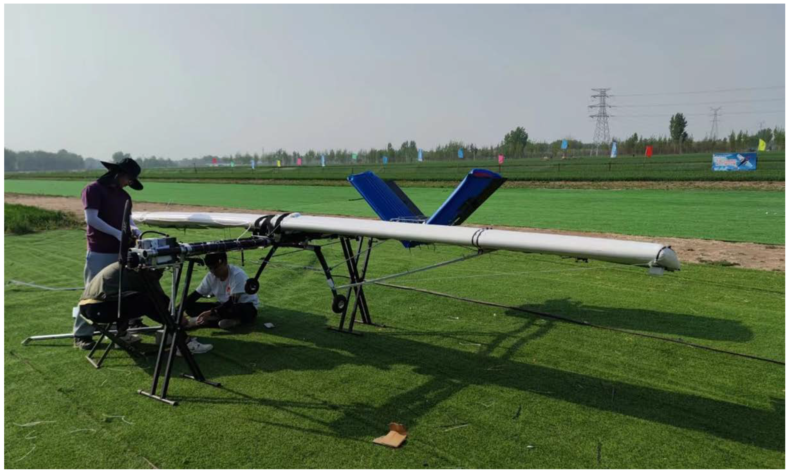
The first prototype (Prot1) features a conventional aerodynamic layout, with a cantilever monoplane wing configuration and a V-tail arrangement. To facilitate the design and fabrication of the inflatable wings, both the main wing and the tail are designed with rectangular platforms. Regarding airfoil selection, the main wing adopts the NACA4318 airfoil, while the tail uses the traditional symmetric NACA0015 airfoil. The fuselage follows a single-body design, consisting of two telescopic carbon fiber rods that serve to adjust the tail’s control arm, ensuring increased control effectiveness while minimizing the storage volume. Control of Prot1 is achieved through external control surfaces, as introduced in Section 3.3.1, that are mounted on the trailing edges of both the wing and tail. The UAV is powered by a single front-mounted electrical tractor propeller, which minimizes airflow interference and improves propulsion efficiency. The electrical power is supplied by a LiPo battery, and all propulsion system components are off-the-shelf products. The avionic system, including the flight control computer, integrated navigation equipment, sensors, and servo systems, also consists of mature off-the-shelf components. Additionally, the aircraft is equipped with a tricycle landing gear for taking off and landing during low-altitude testing.
Following the standard UAV design iteration process (see in [31,33]), the final tested version of Prot1 is shown in Figure 14. The take-off weight is 40 kg, with a cruise velocity of approximately 16 m/s at low altitude. The geometric parameters of Prot1 are summarized in Table 1.

4.3. Evaluation of Roll Control Effectiveness

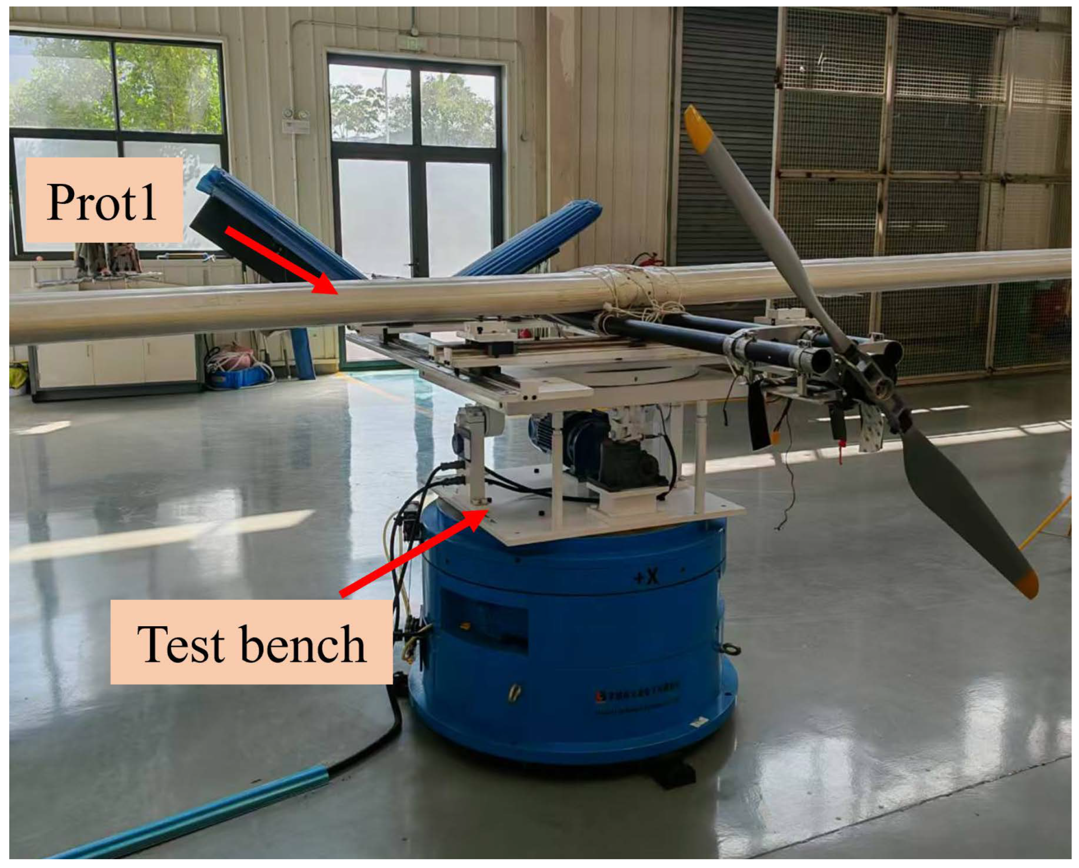
The evaluation of roll-control effectiveness for Prot1 incorporates several parameters, with basic geometric details provided in Table 1. Pertinent roll control and inertial properties, determined through simulation or testing, are listed in Table 2. The UAV’s moments of inertia were experimentally measured using a weight and moment-of-inertia test bench, as shown in Figure 15. The roll damping coefficient ( C l p ) and the variation of the rolling moment coefficient with respect to aileron deflection ( C l δ A ) were determined using the commercial CFD software STAR CCM+® 2310. The maximum aileron deflection angle is defined as a design parameter.
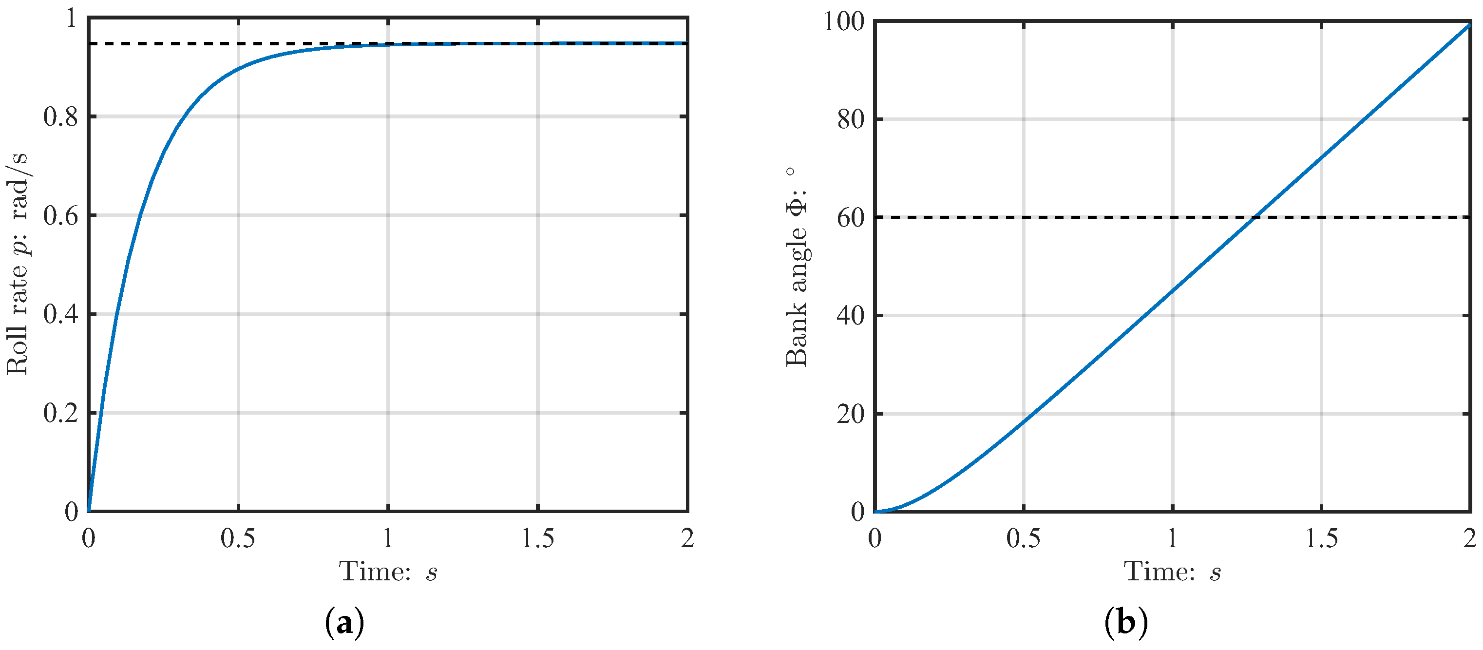
Based on the roll control effectiveness evaluation method described in Section 3.2, along with the design and performance parameters of Prot1, we developed a roll simulation model in MATLAB® R2022b. Roll control responses for Prot1 to a step input of the maximum deflection of the external ailerons, including the roll rate p and the bank angle Φ , are presented in Figure 16. This figure demonstrates that the roll rate stabilizes after 1 s, while a 60 ° bank angle is achieved in approximately 1.3 s at maximum aileron deflection. This performance meets ” Level 1” handling quality requirements defined earlier (see in Section 3.1), confirming that the external ailerons provide sufficient roll control effectiveness.

4.4. Flight Tests of Prot1

Starting from April 2024, flight tests of Prot1 were conducted to demonstrate the feasibility of the aerodynamic layout and stability performance through standard flight procedures. The flight test went successfully, confirming the feasibility of the configuration. Figure 17 presents some photos taken during the flight test.
The drone pilot’s evaluation indicated that the control system responded actively and effectively throughout the flight. All control criteria were met, highlighting the effectiveness of the external control surface manipulation method. Additionally, despite multiple rollovers and ground impacts, the wing remained intact, demonstrating significant resistance to impact and damage. However, the asymmetric torsional issue in the main wing, resulting from the manufacturing process, presented significant challenges, particularly in maintaining stable roll control. This issue will be analyzed in greater detail in the following sections.

4.5. Challenges Encountered by Prot1

During the development and flight testing of the prototype, several issues were identified, particularly with the critical component–the inflatable wing. The main issues are summarized as follows:
Issue 1: Limited load-bearing capability of inflatable wing.
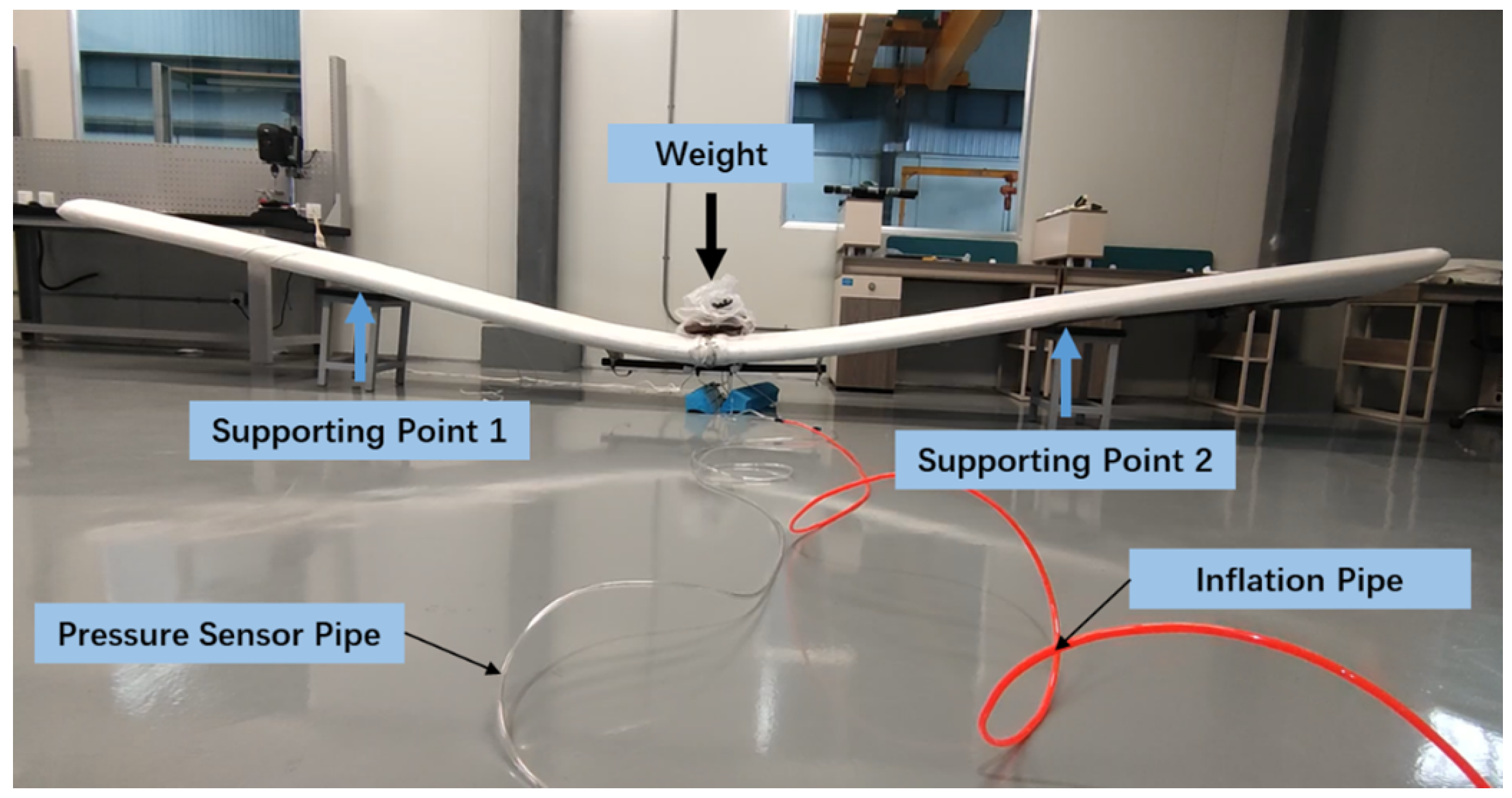
Figure 18 presents a simple static load test performed on the wing to simulate the loading conditions of Prot1. The applied load at the wing’s center corresponds to the takeoff weight of Prot1, excluding the wing’s self-weight. The results indicate that the wing of Prot1 exhibited considerable deformation under the designed takeoff weight and internal inflation pressure. Although no structural instability was observed, this deformation negatively impacts the overall flight stability of the aircraft, primarily due to the dihedral effect [33]. Theoretically, increasing the internal pressure of the inflatable wing could enhance its load-bearing performance. However, due to limitations in manufacturing processes and materials, further increases in internal pressure are not currently feasible.
Issue 2: Uncontrollable torsion of inflatable wing.
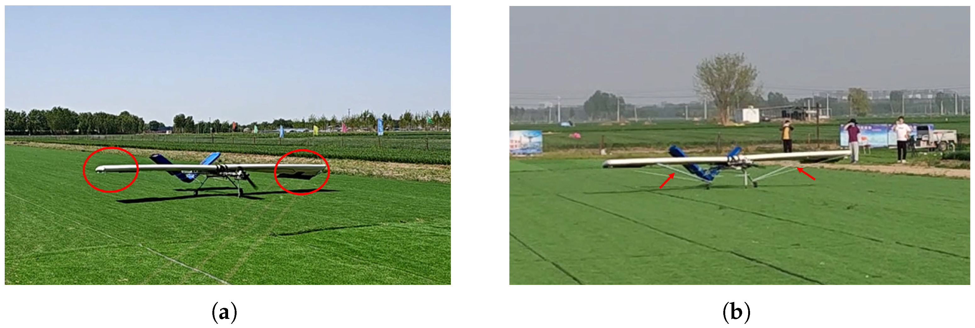
Two primary factors have been identified as contributors to the uncontrollable torsion of the inflatable wing, as shown in Figure 19. First, the manufacturing process for the inflatable wing is still under development, and there are currently no standardized tools or procedures in place for consistent production. The welding of internal spars was carried out manually, which makes it difficult to ensure uniformity and process repeatability across units. Second, the fabric weave itself is occasionally inconsistent, such as misalignment between the warp and weft threads, leading to uneven force distribution when the wing is inflated. This also results in torsional deformation, as demonstrated in the left image of Figure 20. Such torsion induces an unbalanced roll during flight, which makes effective control more challenging.
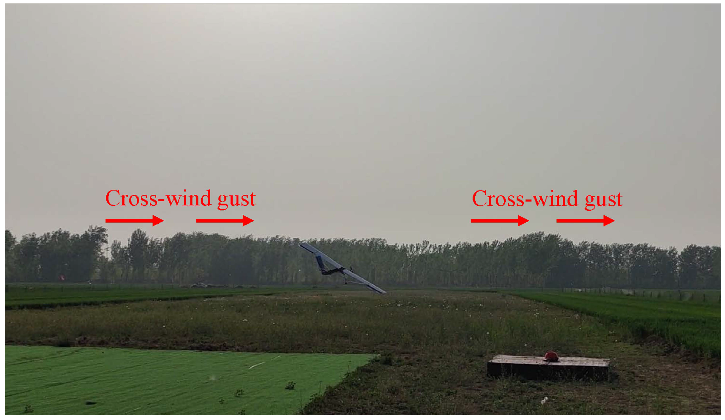
To mitigate this torsional issue, auxiliary supports and ropes were added to Prot1 to counteract the torsion. Although this correction reduced the torsional deformation, it increased the structural mass by approximately 1 kg, which is a significant drawback for this light-weight aircraft where weight is critical. Nevertheless, as illustrated in the right image of Figure 20, these measures were not sufficient to fully resolve the problem. Although the external ailerons provided effective roll control, frequent oscillations in the roll axis were observed due to the asymmetric torsion of the wing, requiring continuous control adjustments. Ultimately, during one of the test flights, the aircraft experienced an uncontrollable roll and subsequently crashed shortly after takeoff. This failure was due to the asymmetric condition of the wings, exacerbated by sudden wind gusts, as shown in Figure 21.

5. Prototype 2: Design and Fight Tests

5.1. Key Improvements

As shown in Figure 22, based on the issues encountered during the development and flight testing of the first prototype, several adjustments have been made to the overall design of the second-generation prototype (Prot2). The main changes and their underlying reasons are as follows:
  • Transition from a single-fuselage to a twin-fuselage configuration: Due to the limited load-bearing capacity of the inflatable wing, the twin-fuselage design facilitates a more uniform load distribution across the inflatable wings, thereby reducing dependency on the internal pressure for structural support.
  • Redesign of inflatable wing: The initial 6-m single inflatable wing has been modified into a segmented design. This change reduces the manufacturing complexity and mitigates the torsional deformation issues observed in the first prototype.
  • Redesign of control surfaces: The external trailing-edge control surfaces of the first prototype have been replaced with fully movable ailerons, along with fully movable horizontal and vertical tails. This design can compensate for the torsional issues associated with the main wing by utilizing asymmetric deflection of the fully movable ailerons.
  • Upgrade of propulsion system: The single-thrust configuration has been upgraded to a twin-thrust setup. This allows for differential thrust, providing auxiliary yaw control input.

5.2. Vehicle Overview

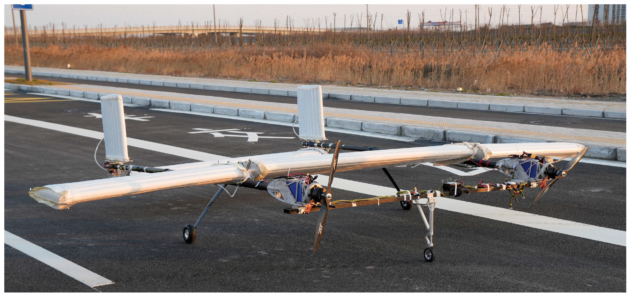
As shown in Figure 23, the second prototype still features a conventional wing-tail configuration, but with a twin-boom fuselage. The wing consists of a segmented straight-wing design, with a 2-m main wing section located between the two booms. Each side of the main wing is equipped with a 1.6-m fully movable outer wing, which serves as the ailerons and provides roll control through anti-symmetric deflections. The tail assembly adopts a U-shaped layout, with the horizontal tail positioned between the two fuselage booms. The horizontal tail is fully movable, enabling precise pitch control. To simplify the design, the horizontal tail shares the same straight-section configuration as the main wing. Its larger surface area allows it to bear a portion of the load, thus enabling a wider range of center-of-gravity adjustments. Two vertical tails are mounted on the rear of each fuselage boom, both fully movable to provide yaw control. The propulsion system utilizes a twin-thrust electric propulsion configuration, with motors and propellers mounted on each boom. This setup allows for differential thrust, which can assist with yaw control. All propulsion and avionics components for Prot2 are identical to those used in Prot1. The aircraft is also equipped with a tricycle landing gear, with the main and front landing gear mounted on the respective rear and front auxiliary crossbeams. The final design take-off weight of Prot2 is 45 kg, with a cruise velocity of approximately 20 m/s at low altitude.
Compared to Prot1, Prot2 experiences an increase in weight due to configuration changes, primarily resulting from the addition of more batteries and motors. However, the overall payload remains unchanged. With the upgraded propulsion system, Prot2 is capable of achieving a higher flight speed, which accommodates the increased take-off weight. The geometric parameters for the second prototype are summarized in Table 3.

5.3. Evaluation of Control Effectiveness

Following the same methodology applied to Prot1, roll control is analyzed to evaluate the effectiveness of the fully movable ailerons on Prot2. Table 4 summarizes the relevant inertial characteristics and roll-control parameters.
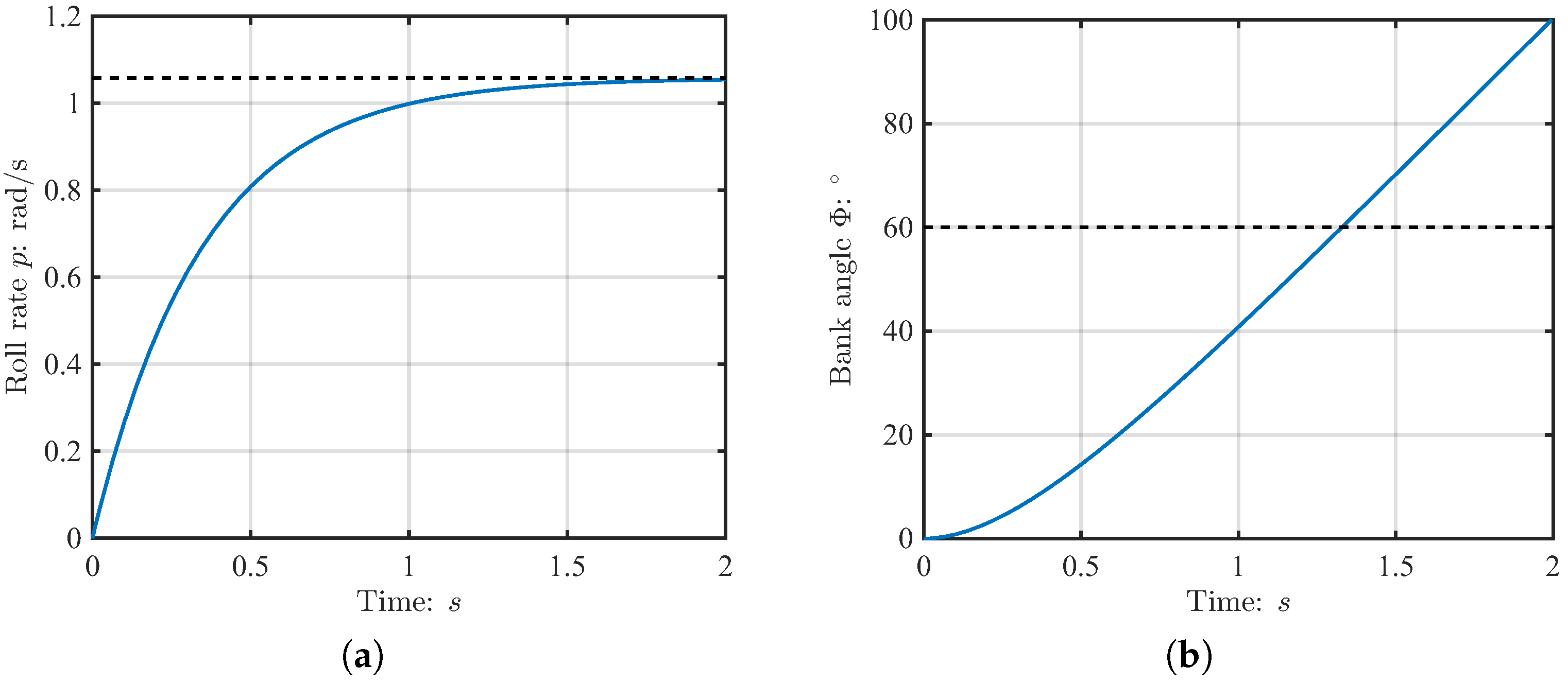
Roll control responses for Prot2 to a step input of the maximum deflection of the fully movable ailerons, including roll rate p and bank angle Φ , are shown in Figure 24. The figure indicates that the roll rate stabilizes within 2 s , while a 60 ° bank angle is attained in approximately 1.4 s at maximum aileron deflection. This performance reaffirms “ Level 1” handling quality requirements, confirming that fully movable ailerons constitute an effective roll control methodology.

5.4. Flight Tests of Prot2

Starting in February 2025, a comprehensive flight-test campaign was undertaken to evaluate Prot2’s performance across various phases: ground taxiing, takeoff and landing, climb, and cruise. Figure 25 illustrates one flight trial of Prot2, showing the UAV from the ground perspective alongside the onboard camera perspective.
The results of the flight tests confirmed the viability of Prot2’s aerodynamic layout. Throughout taxiing, liftoff, climb, and cruise, the vehicle remained stable and fully controllable, with no significant handling anomalies observed. According to the evaluation by the drone pilot, the fully movable ailerons, as well as the horizontal and vertical tails, exhibited rapid and precise responses to control inputs, providing sufficient roll, pitch, and yaw authority to meet all maneuverability requirements. Notably, no torsional issues were encountered with the wing in this prototype. Although the segmented wing structure and its flexible attachments to the fuselage were initially expected to potentially degrade handling qualities, flight tests revealed that the effects of this flexibility were negligible. In conclusion, the Prot2 flight-test program validated the feasibility of its aerodynamic configuration and confirmed its practicality to meet the intended performance and control specifications.

5.5. Prototypes Flight Tests Summary

Table 5 summarizes the flight testing records for the two prototypes as a comparison. According to the test results, the feasibility of using inflatable wings on aircraft has been demonstrated, showcasing several key advantages, including excellent impact resistance, high foldability, and low structural weight. Both aerodynamic configurations were found to be viable. Additionally, the two proposed control strategies, specifically tailored for inflatable wings, were demonstrated to provide adequate control effectiveness.
However, limitations in current material properties and manufacturing processes restrict the load-bearing capacity of inflatable wings and render them prone to uncontrolled torsional deformations. This issue is particularly pronounced in long, high-aspect-ratio wings, as observed in Prot1. The enhancements introduced in Prot2, including a twin-fuselage design, effectively optimize load distribution across the wing, promoting more uniform load sharing and reduced lower bending loads. Additionally, the segmented wing design simplifies the manufacturing process. Consequently, flight tests of Prot2 exhibited improved performance, suggesting that multi-fuselage designs are better suited for inflatable wing applications.
Furthermore, both prototypes shared the common issue of poor wind resistance. This is attributed to the relatively low load-bearing capacity and designed wing-loading, which requires larger wing areas for a given takeoff weight, making them more susceptible to wind disturbances. Therefore, until the load-bearing capacity of inflatable wings can be effectively improved, these inflatable aircraft are better suited for more stable flight environments, such as the stratosphere or Martian atmosphere.

6. Conclusions

This study involved the design, development, and flight demonstration of two inflatable-winged UAVs, Prot1 and Prot2, each featuring distinct configurations. The inflatable-wing concept was rigorously evaluated through both ground and flight experiments, which confirmed its feasibility and highlighted several key advantages, including excellent impact resistance, high foldability, and superior structural stability. It was demonstrated that a segmented wing design with a multi-boom configuration is particularly well-suited for inflatable wings, especially when the wings have a high aspect ratio. Additionally, two novel manipulation methods for the inflatable wing, both of which could be easily implemented using small servos, were tested and shown to be effective during flight.
However, the tests also revealed several inherent limitations of inflatable wings. First, the manufacturing process for inflatable wings remains underdeveloped, leading to challenges in ensuring consistent quality control and dimensional accuracy. Second, unlike conventional rigid wings, the load-bearing capacity of inflatable wings cannot be easily increased. While increasing internal inflation pressure does improve stiffness, it simultaneously places excessive demands on existing materials and fabrication techniques. As a result, achieving a high-aspect-ratio, fully cantilevered monoplane configuration remains unfeasible, making the multi-fuselage layout a more suitable alternative for inflatable wing applications.
Furthermore, the low wing-loading characteristic of inflatable-wing UAVs makes them particularly vulnerable to wind disturbances. In low-altitude, high-wind conditions, both prototypes frequently encountered sudden gusts or turbulence that caused loss of control and rollovers. These findings suggest that inflatable wings may be better suited for relatively stable, high-altitude flight environments, such as the stratosphere or Mars, where wind conditions are calmer and more conducive to flight. Consequently, the direct deployment of inflatable-winged aircraft should be considered for these particular environments, where atmospheric conditions are more favorable for sustained flight.
Regarding some promising future research directions for inflatable-winged aircraft, one key area is the development of strategies to enhance wind resistance under low-altitude, high-wind conditions. For example, the application of advanced robust control algorithms, combined with gust detection and prediction techniques, could significantly improve UAV stability and performance in such environments. These approaches can be extended to all fixed-wing aircraft, particularly those with low wing-loading designs. Another key research direction, aligned with the ultimate objective of the current funded project, is the investigation of in-flight deployment, inflation and transition characteristics of inflatable-winged aircraft, which is essential for enabling reliable airborne deployment.

Author Contributions

Conceptualization, H.G. and Z.M.; methodology, H.G., Y.X. (Yonghui Xu) and Z.M.; software, H.G. and Z.M.; validation, Y.X. (Yixiang Xu), D.S. and X.C.; formal analysis, H.G.; investigation, H.G., Y.X. (Yonghui Xu) and Z.M.; resources, X.C. and B.C.; data curation, H.G., Y.X. (Yonghui Xu) and Z.M.; writing—original draft preparation, H.G.; writing—review and editing, D.S. and Y.X. (Yixiang Xu); visualization, H.G.; supervision, Y.X. (Yixiang Xu), D.S. and X.C.; project administration, X.C. and B.C.; funding acquisition, X.C. All authors have read and agreed to the published version of the manuscript.

Funding

This research was funded by the Ningbo Key Research and Development Project (Contract No. 2023Z051) under the Ningbo Municipal Science and Technology Bureau.

Data Availability Statement

The data presented in this study are available on request from the corresponding authors.

Acknowledgments

This paper is supported by Ningbo Key Professional Think Tank “Centre for Low Carbon Economy and Scientific Innovation, University of Nottingham Ningbo China”. The authors would like to thank Junqi Wang, the on-board system engineer, and Shuang Lu, the UAV pilot, for their valuable support to this project.

Conflicts of Interest

The authors declare no conflicts of interest.

References

  1. Stadvec, E. The Inflatoplane; Essco: Akron, OH, USA, 1980. [Google Scholar]
  2. Cocke, B.W. Wind-Tunnel Investigation of the Aerodynamic and Structural Deflection Characteristics of the Goodyear Inflatoplane; NACA-RM-L58E09; National Advisory Committee for Aeronautics: Washington, DC, USA, 1958. [Google Scholar]
  3. Jacob, J.; Smith, S.; Cadogan, D.; Scarborough, S. Expanding the Small UAV Design Space with Inflatable Wings. In Proceedings of the Aerospace Technology Conference and Exposition, Long Beach, CA, USA, 18–20 September 2007. [Google Scholar] [CrossRef]
  4. Cadogan, D.; Smith, T.; Lee, R.; Scarborough, S.; Graziosi, D. Inflatable and Rigidizable Wing Components for Unmanned Aerial Vehicles. In Proceedings of the 44th AIAA/ASME/ASCE/AHS/ASC Structures, Structural Dynamics, and Materials Conference, Norfolk, VA, USA, 7–10 April 2003. [Google Scholar] [CrossRef]
  5. Murray, J.; Pahle, J.; Thornton, S.; Vogus, S.; Frackowiak, T.; Mello, J.; Norton, B. Ground and Flight Evaluation of a Small-Scale Inflatable-Winged Aircraft. In Proceedings of the 40th AIAA Aerospace Sciences Meeting & Exhibit, Reno, NV, USA, 14–17 January 2002. [Google Scholar] [CrossRef]
  6. Simpson, A.D.; Rawashdeh, O.; Smith, S.W.; Jacob, J.; Smith, W.T.; Lumpp, J.E. BIG BLUE: High-altitude UAV demonstrator of Mars airplane technology. In Proceedings of the 2005 IEEE Aerospace Conference, Big Sky, MT, USA, 5–12 March 2005. [Google Scholar] [CrossRef]
  7. Simpson, A.; Jacob, J.; Smith, S.; Rawashdeh, O.; Lumpp, J.; Smith, W. BIG BLUE II: Mars Aircraft Prototype with Inflatable-Rigidizable Wings. In Proceedings of the 43rd AIAA Aerospace Sciences Meeting and Exhibit, Reno, NV, USA, 8–13 January 2005. [Google Scholar] [CrossRef]
  8. Wade, P.; Rachel, N. Historical Perspective on Inflatable Wing Structures. In Proceedings of the 50th AIAA/ASME/ASCE/AHS/ASC Structures, Structural Dynamics, and Materials Conference, Palm Springs, CA, USA, 4–7 May 2009. [Google Scholar] [CrossRef]
  9. Lebeau, R.; Reasor, D.; Gilliam, T.; Schloemer, A.; Hauser, T.; Johansen, T. Numerical Comparison of Flow over Bumpy Inflatable Airfoils. In Proceedings of the 47th AIAA Aerospace Sciences Meeting including the New Horizons Forum and Aerospace Exposition, Orlando, FL, USA, 5–8 January 2009. [Google Scholar] [CrossRef]
  10. Ghobadi, K.; Pifer, E.; Lebeau, R.; Bramesfeld, G.; Mcquilling, M. A Computational and Experimental Investigation of Flow Over an Inflatable Wing. In Proceedings of the 30th AIAA Applied Aerodynamics Conference, New Orleans, LA, USA, 25–28 June 2012. [Google Scholar] [CrossRef]
  11. Beltz, J.; Lebeau, R. A Comparison of Computational and Experimental Results for Three-Dimensional Flow over a Undulating Inflatable Wing. In Proceedings of the 34th AIAA Applied Aerodynamics Conference, Washington, DC, USA, 13–17 June 2016. [Google Scholar] [CrossRef]
  12. Breuer, J.; Ockels, W.; Luchsinger, R. An inflatable wing using the principle of Tensairity. In Proceedings of the 48th AIAA Structures, Structural Dynamics and Materials Conference, Honolulu, HI, USA, 23–26 April 2007; Volume 5. [Google Scholar] [CrossRef]
  13. Ma, N.; Liu, L.; Meng, F.; Meng, J. Structural design and modal behaviors analysis of a new swept baffled inflatable wing. Def. Technol. 2023, 24, 382–398. [Google Scholar] [CrossRef]
  14. Wei, J.; Hou, S.; Xia, Q.; Tan, H. Structural design and dynamic analysis of an inflatable delta wing. Aerosp. Sci. Technol. 2023, 139, 108371. [Google Scholar] [CrossRef]
  15. Rakshith, K.; Dusane, C.; Mistri, S.; Pant, R. Analytical Modelling of Baffled Inflatable Wing for Failure Prediction. In Proceedings of the AIAA Aviation 2019 Forum, Dallas, TX, USA, 17–21 June 2019. [Google Scholar] [CrossRef]
  16. Mao, Z.; Li, Z.; Chen, B.; Ge, H.; Xu, Y.; Wang, J.; Chen, X. Prediction method for mechanical properties of inflatable wing and its buckling failure mechanism. Aerosp. Sci. Technol. 2025, 163, 110304. [Google Scholar] [CrossRef]
  17. Cadogan, D.; Scarborough, S.; Gleeson, D.; Dixit, A.; Jacob, J.; Simpson, A. Recent Development and Test of Inflatable Wings. In Proceedings of the 47th AIAA/ASME/ASCE/AHS/ASC Structures, Structural Dynamics, and Materials Conference, Newport, RI, USA, 1–4 May 2006. [Google Scholar] [CrossRef]
  18. Butt, L.; Kurdi, M.; Kapania, R.; Asheghian, L. Aeroelastic Analysis and Optimization of a Rigid/Inflatable Wing. In Proceedings of the AIAA/ASME/ASCE/AHS/ASC Structures, Structural Dynamics and Materials Conference, Denver, CO, USA, 4–7 April 2011. [Google Scholar] [CrossRef]
  19. Simpson, A.; Smith, S.; Jacob, J. Aeroelastic Behavior of Inflatable Wings: Wind Tunnel and Flight Testing. In Proceedings of the 45th AIAA Aerospace Sciences Meeting and Exhibit, Reno, NV, USA, 8–11 January 2007. [Google Scholar] [CrossRef]
  20. Rendall, T.; Chang, C.; Marzocca, P.; Bollt, E.; Zamankhan, P. Aeroelastic Behavior of a Non-rigidizable Inflatable UAV Wing. In Proceedings of the 47th AIAA/ASME/ASCE/AHS/ASC Structures, Structural Dynamics, and Materials Conference, Newport, RI, USA, 1–4 May 2006. [Google Scholar] [CrossRef]
  21. Simpson, A.; Jacob, J. Aerodynamic Control of an Inflatable Wing Using Wing Warping. In Proceedings of the 35th AIAA Fluid Dynamics Conference and Exhibit, Toronto, ON, Canada, 5–9 June 2005. [Google Scholar] [CrossRef]
  22. Simpson, A.; Jacob, J.; Smith, S. Flight Control of a UAV with Inflatable Wings with Wing Warping. In Proceedings of the 24th AIAA Applied Aerodynamics Conference, San Francisco, CA, USA, 5–8 June 2006. [Google Scholar] [CrossRef]
  23. Wang, Z.; Wang, H. Inflatable Wing Design Parameter Optimization Using Orthogonal Testing and Support Vector Machines. Chin. J. Aeronaut. 2012, 25, 887–895. [Google Scholar] [CrossRef]
  24. Shi, Q.; Wang, H. Inflatable airfoil structure optimization on flying wing Buoyancy-lifting unmanned aerial vehicles. In Proceedings of the 2017 IEEE International Conference on Unmanned Systems (ICUS), Beijing, China, 27–29 October 2017; pp. 254–259. [Google Scholar] [CrossRef]
  25. Ma, N.; Meng, J.; Luo, J.; Liu, Q. Optimization of thermal-fluid-structure coupling for variable-span inflatable wings considering case correlation. Aerosp. Sci. Technol. 2024, 153, 109448. [Google Scholar] [CrossRef]
  26. Ge, H.; Xu, Y.; Sun, D.; Chen, X.; Chen, B. Design and Flight Test of a Compact and Rapidly-Deployable Air-Launched Inflatable-Winged Aircraft. In Proceedings of the AIAA SCITECH 2025 Forum, Orlando, FL, USA, 6–10 January 2025. [Google Scholar] [CrossRef]
  27. Moorhouse, D.J.; Woodcock, R.J. Military Specification-Flying Qualities of Piloted Airplanes; Technical Report MIL-F-8785C; Department of Defense: Dayton, OH, USA, 1980. [Google Scholar]
  28. Moorhouse, D.J.; Woodcock, R.J. Background Information and User Guide for MIL-F-8785C, Military Specification-Flying Qualities of Piloted Airplanes; Technical Report AFWAL-TR-81-3109; Flight Dynamics Laboratory, Air Force Wright Aeronautical Laboratories, Wright-Patterson AFB: Dayton, OH, USA, 1982. [Google Scholar]
  29. Prosser, C.F.; Wiler, C.D. RPV Flying Qualities Design Criteria; Technical Report AFFDL-TR-76-125; Air Force Flight Dynamics Laboratory: Dayton, OH, USA, 1976. [Google Scholar]
  30. Greene, K.M.; Kunz, D.L.; Cotting, M.C. Toward a Flying Qualities Standard for Unmanned Aircraft. In Proceedings of the AIAA Atmospheric Flight Mechanics Conference, National Harbor, MD, USA, 13–17 January 2014. [Google Scholar] [CrossRef]
  31. Sadraey, M.H. Aircraft Design; John Wiley & Sons, Ltd.: Hoboken, NJ, USA, 2012; Chapter 12; pp. 631–753. [Google Scholar] [CrossRef]
  32. Doepke, E.; Ashcraft, S.W.; Thamann, M.A.; Smith, S.W. Design of a Rapid Prototype Wing Warping Test Aircraft. In Proceedings of the 54th AIAA/ASME/ASCE/AHS/ASC Structures, Structural Dynamics, and Materials Conference, Boston, MA, USA, 8–11 April 2013. [Google Scholar] [CrossRef]
  33. Gudmundsson, S. General Aviation Aircraft Design-Applied Methods and Procedures; Butterworth-Heinemann: Waltham, MA, USA, 2022. [Google Scholar] [CrossRef]
Figure 1. Structure of the inflatable wing.
Aerospace 12 00976 g001
Figure 2. Left: Setup of load test. Right: Comparison of experimental and simulation results of the force-displacement curves at the inflation pressure of 70 kPa [16].
Aerospace 12 00976 g002
Figure 3. Low-speed wind-tunnel test of inflatable wing [26].
Aerospace 12 00976 g003
Figure 4. Pressure retention test.
Aerospace 12 00976 g004
Figure 5. Foldability test.
Aerospace 12 00976 g005
Figure 6. Incremental changes in lift and roll damping that generate a rolling motion, reproduced from [31].
Aerospace 12 00976 g006
Figure 7. Inflatable wing with an external trailing-edge control surface (aileron).
Aerospace 12 00976 g007
Figure 8. Actuation mechanism for the external aileron.
Aerospace 12 00976 g008
Figure 9. Roll control effectiveness of the external inflatable ailerons.
Aerospace 12 00976 g009
Figure 10. Main wing with fully movable ailerons.
Aerospace 12 00976 g010
Figure 11. Actuation mechanism for the fully movable aileron.
Aerospace 12 00976 g011
Figure 12. Roll control effectiveness of the fully movable ailerons.
Aerospace 12 00976 g012
Figure 13. Example flight profile of a rocket-launched UAV [26].
Aerospace 12 00976 g013
Figure 14. Prot1 before testing.
Aerospace 12 00976 g014
Figure 15. Measurement of mass properties and moments of inertia for Prot1.
Aerospace 12 00976 g015
Figure 16. Roll control response for Prot1. (a) Roll rate. (b) Bank angle.
Aerospace 12 00976 g016
Figure 17. Flight tests of Prot1, with the UAV highlighted by a red circle in the right image.
Aerospace 12 00976 g017
Figure 18. Load tests of inflatable wing.
Aerospace 12 00976 g018
Figure 19. Uncontrollable torsion issue of the inflatable wing, highlighted by red lines.
Aerospace 12 00976 g019
Figure 20. Uncontrollable torsion issue of the inflatable wing for Prot1. (a) Uncorrected state exhibiting significant asymmetric torsion, highlighted by red circles. (b) Corrected state with the implementation of auxiliary supports and ropes, indicated by red arrows.
Aerospace 12 00976 g020
Figure 21. Rollover and crash of Prot1.
Aerospace 12 00976 g021
Figure 22. Evolvement of design concepts: Prot1 (left) and Prot2 (right).
Aerospace 12 00976 g022
Figure 23. Prot2 before testing.
Aerospace 12 00976 g023
Figure 24. Roll control response for Prot2. (a) Roll rate. (b) Bank angle.
Aerospace 12 00976 g024
Figure 25. Flight tests of Prot2: ground view (left) with the UAV highlighted by a red circle, and onboard camera view (right).
Aerospace 12 00976 g025
Table 1. Geometric parameters of Prot1.
ComponentsParametersValues
WingWingspan6 m
Mean chord length0.6 m
Aspect ratio10
AirfoilNACA4318 (Inflatable)
Tail (single side)Wingspan1.2 m
Mean chord length0.5 m
Aspect ratio2.4
AirfoilNACA0015 (Inflatable)
FuselageLength3.5 m (telescopic)
Table 2. Roll dynamics parameters of Prot1.
Parameter I x C l p C l δ A δ A max
Value60−0.550.2820
Unitkg·m2degrees
Data sourceExperimentCFDCFDDesign result
Table 3. Geometric parameters of Prot2.
ComponentsParametersValues
WingWingspan5.2 m
Mean chord length0.6 m
Aspect ratio8.67
AirfoilNACA4318 (Inflatable)
Horizontal TailWingspan2 m
Mean chord length0.6 m
Aspect ratio3.33
AirfoilNACA4318 (Inflatable)
Vertical Tail (single side)Wingspan0.5 m
Mean chord length0.5 m
Aspect ratio1
AirfoilNACA0015 (Inflatable)
FuselageLength3.5 m (twin-boom)
Table 4. Roll dynamics parameters of Prot2.
Parameter I x C l p C l δ A δ A max
Value52−0.480.48
Unitkg·m2degrees
Data sourceExperimentCFDCFDDesign result
Table 5. Comparison of Prot1 and Prot2 from test results.
ItemsProt1Prot2
Basic configurationSingle-fuselage, cantilevered main wing, single-thrust systemTwin-fuselage, segmented wing sections, twin-thrust system
Maximum takeoff weight40 kg45 kg
Manipulation methodExternal trailing-edge control surfaces on the main wing and tailsFully movable ailerons and tails
Flights
(including ground taxiing tests)
10 times16 times
Maximum flight altitude≈40 m≈75 m
Maximum velocity reached≈20 m/s≈25 m/s
Control responses
(evaluated by the drone pilot)
-Pitch: Adequate-Pitch: Adequate
-Yaw: Adequate-Yaw: Adequate
-Roll: Adequate-Roll: Adequate
Anomalies before flightAsymmetric torsion in the main wingNone
Corrective measuresAuxiliary supports and ropes
Anomalies during flight
(evaluated by the drone pilot)
- Sustained oscillations in the roll axis (due to wing asymmetric torsion), necessitating continuous control adjustments- Poor wind resistance, occasional instability under gusty conditions
- Poor wind resistance, occasional instability under gusty conditions
Wing deformation (during flight)-Obvious upwards deformation without auxiliary supports and ropes-Not visually noticeable
-Not visually noticeable with auxiliary supports and ropes
Flight crashesYes, caused by combined effect of wing asymmetric torsion and sudden crosswindYes, caused by sudden crosswind
Other observationsInflatable wing remained intact after ground rollovers and crashInflatable wing remained intact after crash
Disclaimer/Publisher’s Note: The statements, opinions and data contained in all publications are solely those of the individual author(s) and contributor(s) and not of MDPI and/or the editor(s). MDPI and/or the editor(s) disclaim responsibility for any injury to people or property resulting from any ideas, methods, instructions or products referred to in the content.