Article

Design and Research of Lorentz Force Magnetic Levitation Vibration Isolation Platform

1
Graduate School, Space Engineering University, Beijing 101416, China
2
Department of Aerospace Science and Technology, Space Engineering University, Beijing 101416, China
*
Author to whom correspondence should be addressed.
Aerospace 2025, 12(11), 965; https://doi.org/10.3390/aerospace12110965 (registering DOI)
Submission received: 3 September 2025 / Revised: 10 October 2025 / Accepted: 26 October 2025 / Published: 28 October 2025
(This article belongs to the Section Astronautics & Space Science)

Abstract

To address the micro-vibration isolation requirements of precision payloads in spacecraft, a Lorentz force-based magnetic levitation series vibration isolation platform is proposed. The Lorentz force actuator, overall coupling characteristics, and low-frequency vibration isolation performance of the platform are optimized, simulated, and experimentally validated. During the actuator design phase, an equivalent magnetic circuit model and an equivalent current model are established for the planar actuator. The theoretical relationship between magnetic flux density in the air gap and magnetization length is derived. Through finite element simulation, the optimal magnetization length is determined to be 7 mm. For the coupling analysis, a dynamic model of the platform is developed to quantify the coupling effects between translational and rotational motions. To evaluate the low-frequency vibration isolation performance, sinusoidal displacement at various frequencies is applied to emulate the space vibration environment and validate the isolation capability. The results show that the platform has low translational-rotational cross-coupling, and the vibration transmissibility of low-frequency micro-vibration is less than 35 dB. This system offers a high-precision, low-coupling solution for vibration isolation in precision optical instruments.

1. Introduction

In recent years, with the continuous advancement of aerospace science and technology worldwide, missions such as high-resolution remote sensing, astronomical observation, and space science experiments have placed increasingly stringent demands on highly stable ultra-quiet vibration isolation platforms [1,2]. Research on micro-vibration isolation platforms continues to intensify, reflecting a trend toward multidisciplinary integration. Requirements for attitude pointing accuracy, stability, and micro-vibration isolation capability of payload platforms are becoming ever more demanding. As a result, vibration isolation technology has emerged as a critical bottleneck limiting the performance enhancement of spacecraft.
To mitigate or eliminate micro-vibrations in on-orbit satellites, researchers domestically and internationally have proposed three main approaches. The first involves increasing structural stiffness [3]—by using higher-strength composite materials to enhance overall rigidity, and optimizing structural design through measures such as adding stiffeners or modifying geometric shapes to improve local stiffness. The second approach focuses on adding damping layers to the existing structure [4], where damping materials or dampers are applied near vibration sources to absorb and dissipate micro-vibration energy, thereby reducing vibration transmission. The third strategy is to introduce a vibration isolation platform between the satellite’s payload module and the service module [5].
The first two approaches aim to suppress vibration generation and propagation at the system level by enhancing structural rigidity or adding damping. However, they exhibit certain limitations. Increasing structural stiffness raises the natural frequency of the system, elevating both manufacturing cost and complexity, while also leading to poor low-frequency vibration isolation performance. Damping materials, on the other hand, are highly sensitive to environmental conditions. Under operational environments, the loss factor of conventional viscoelastic damping materials varies significantly, resulting in limited dynamic vibration isolation performance. The third approach categorizes vibration isolation platforms into contact-based and maglev types, based on the connection method between the satellite platform and the load.
The contact-type vibration isolation platform is well-represented by the six-strut parallel Stewart platform. This configuration was first introduced by Geng, and it served as the basis for the design of the Hexapod Active Vibration Isolation (HAVI) system [6]. Subsequent developments of Stewart-platform-based isolators have largely built upon this original concept. Notable examples include the HT/UW six-support actuator platform by Hood Technology Corporation [7], the UQP platform developed by the U.S. Navy [8], and a satellite-level micro-vibration isolation system designed by the Changchun Institute of Optics, Fine Mechanics and Physics [9]. Extensive follow-up studies [10,11,12] have further advanced this technology through structural improvements, optimization, and innovative parameter design, leading to the development of novel multi-degree-of-freedom platforms with tunable parameters. For instance, the Chinese Academy of Sciences designed a six-degree-of-freedom active vibration isolation system capable of tracking low-frequency signals while attenuating high-frequency vibrations [13]. Despite these advancements, the Stewart platform essentially replaces the rigid connection between the satellite and its payload with a multi-point support scheme. While beneficial, this approach still falls short of fully meeting the requirements for micro-vibration isolation in modern spacecraft applications.
In recent years, non-contact magnetic levitation schemes based on Lorentz force technology have emerged as a new development direction for satellite vibration isolation. A prominent example is the Suppression of Transient Accelerations by Levitation Evaluation (STABLE) system, designed and developed by McDonnell [14,15,16]. Iterative design efforts also led to the Glovebox Integrated Microgravity Isolation Technology (G-LIMIT) system [17,18], which effectively suppresses vibrations within the 0.01–100 Hz range. Further advancing the field, the Shanghai Institute of Satellite Engineering proposed a dual-super platform to decouple the attitude control between the satellite and its payload, a concept successfully applied to the Xihe test satellite [19,20]. Meanwhile, researchers at the Harbin Institute of Technology designed a six-degree-of-freedom maglev micro-vibration isolation system, achieving full spatial active control using eight Lorentz force actuators [21,22]. Another innovative approach is the quasi-zero-stiffness voice coil actuator isolation platform proposed by Li Qing et al. [23], which provides high-performance attenuation across all three translational degrees of freedom. Based on the above research, a performance comparison of typical vibration isolation platforms is summarized in Table 1.
As is evident from Table 1, the maglev-based non-contact vibration isolation platform demonstrates superior performance in terms of both isolation frequency band and transmissibility. Current research predominantly focuses on system-level control with six degrees of freedom (DOF), whereas studies on the coupled motion involving two translational and one rotational DOF within a specific plane remain limited. Therefore, conducting targeted research in this area will not only address the theoretical gap but also hold practical engineering value for enhancing the on-orbit performance of spacecraft designed for specific missions.
This study proposes a novel Lorentz force-based magnetic levitation series vibration isolation platform. The research follows a systematic, multi-stage methodology: It begins with an innovative system design, employing a series configuration and symmetric magnetic circuit design to establish a physical foundation for low coupling. Building upon this foundation, a combined strategy of equivalent magnetic circuit modeling and finite element analysis is adopted for precise actuator modeling and parameter optimization. Subsequently, a coupled dynamic model of the system is developed, and a composite control strategy integrating feedforward decoupling with Active Disturbance Rejection Control (ADRC) is designed to actively suppress residual disturbances. Finally, a comprehensive simulation under full working conditions is conducted to quantitatively evaluate the system’s decoupling performance and vibration isolation efficiency. The overall research workflow is summarized in Figure 1.

2. Lorenz Force Magnetic Levitation Vibration Isolation Platform Scheme Design and Decoupling Analysis

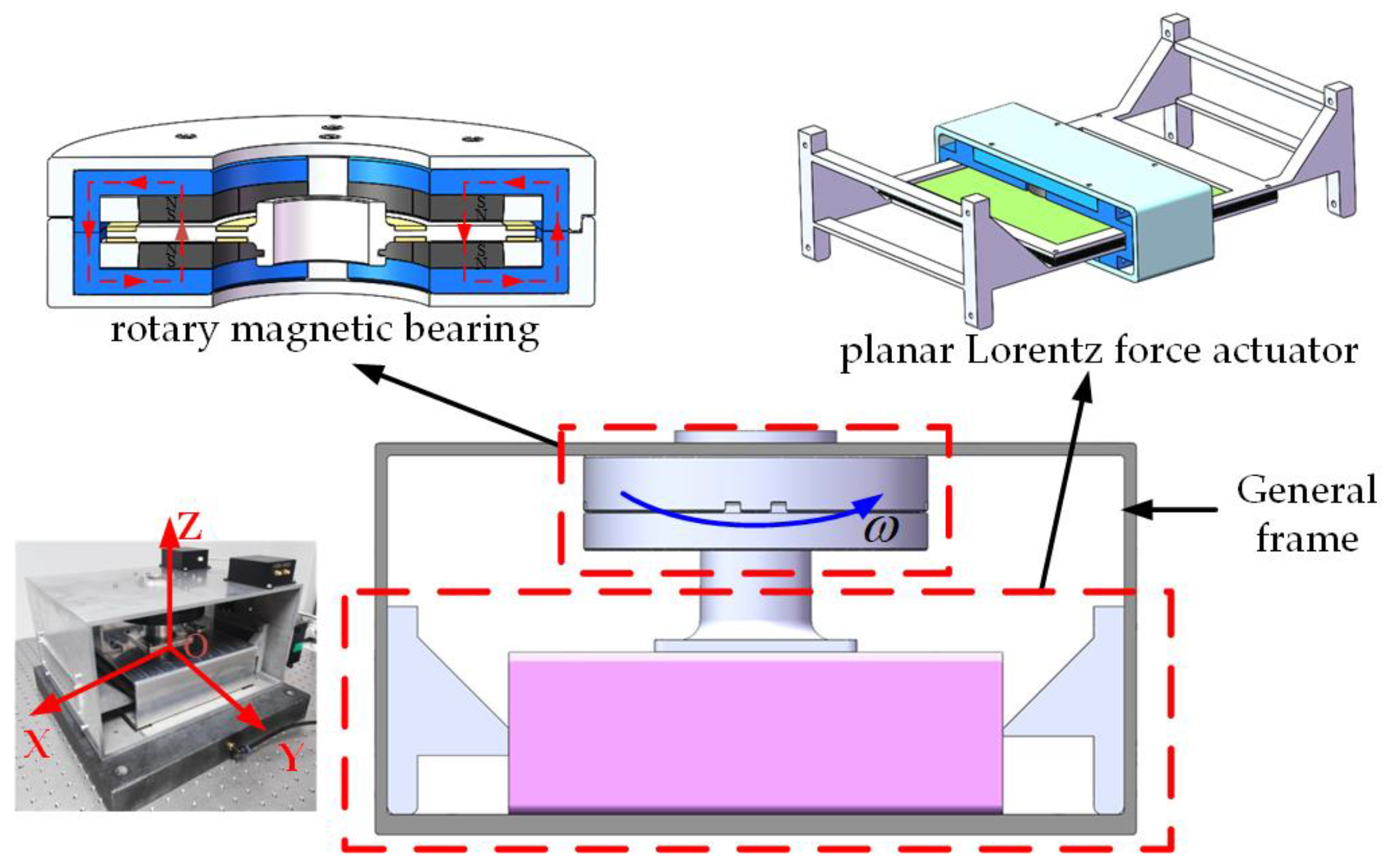
The vibration isolation platform employs a hybrid drive configuration to achieve three-degrees-of-freedom isolation within the plane. Active control of translational motion along the X- and Y-axes is accomplished using a planar Lorentz force actuator, while rotation about the Z-axis is independently regulated by a rotary magnetic bearing. This design effectively avoids dynamic coupling between translational and rotational motions, thereby enhancing decoupling performance and control precision.

2.1. Overall Structure of Lorentz Force Vibration Isolation Platform

The vibration isolation platform employs a three-degree-of-freedom (3-DOF) serial active isolation system comprising a general frame, a rotary magnetic bearing, and a planar Lorentz force actuator. As illustrated in Figure 2, the rotary magnetic bearing provides non-contact torque control for rotation about the Z-axis, while the planar Lorentz force actuator governs translational motion of the platform along the X- and Y-axes. Table 2 shows the mechanical parameters and performance parameters of the platform.
In the design of active vibration isolation platforms, the selection of actuators critically influences the system’s control accuracy and dynamic performance. To entirely eliminate nonlinear disturbances—such as hysteresis and friction inherent in conventional actuators—all actuators in this platform utilize Lorentz force principles.
The rotary magnetic bearing generates a uniform magnetic field via a radially magnetized fan-ring permanent magnet. This configuration ensures that the two segments of the energized coil within the magnetic field consistently experience equal and opposite tangential Lorentz forces across the entire displacement range. As a result, precise control torque is applied to the rotor output shaft attached to the coil, enabling high-precision active rotational control. This design, which has been implemented in prior work [24], exhibits excellent magnetic field uniformity and dynamic response characteristics.
The planar Lorentz force actuator employs an axially magnetized circular permanent magnet to produce a uniform magnetic field. Two orthogonally arranged coils share this magnetic field and operate independently, generating mutually perpendicular Lorentz forces. Since the coils are fixed to the main frame, their reaction forces act upon the permanent magnet, thereby driving the mover assembly—which is rigidly connected to the magnet—to achieve two-degree-of-freedom motion within the plane.
To realize full decoupling among the platform’s degrees of freedom, systematic selection and design of key components—such as the permanent magnet material, yoke (magnetic core) material, and coil support configuration—are essential.
In choosing the permanent magnet material and optimizing its layout, it is important to maintain high magnetic flux density while minimizing vibration-induced interference in the magnetic field. Table 3 summarizes common permanent magnet materials. Considering the requirements of the vibration isolation platform—including high magnetic field uniformity, strong resistance to demagnetization, and compact size—NdFeB is selected as the permanent magnet material.
In selecting magnetic conductive materials, it is essential to optimize the magnetic circuit closure path to minimize hysteresis loss and magnetic flux leakage. Table 4 presents commonly used magnetic conductive materials. An ideal material should exhibit high magnetic flux-carrying capacity and excellent magnetic stability. For this application, 1J22 is chosen as the magnetic conductive material. When compared to other materials with the same cross-sectional area, 1J22 offers the highest saturation magnetic flux density and the maximum operating temperature. Its performance remains stable in high-temperature environments, enabling stronger and more consistent magnetic field strength within the circuit.
For both the rotary magnetic bearing and the planar actuator, the magnetizers are designed with symmetrical structures to ensure uniform distribution of magnetic flux lines and reduce the risk of local saturation.

2.2. Design of Rotary Lorentz Force Magnetic Bearing

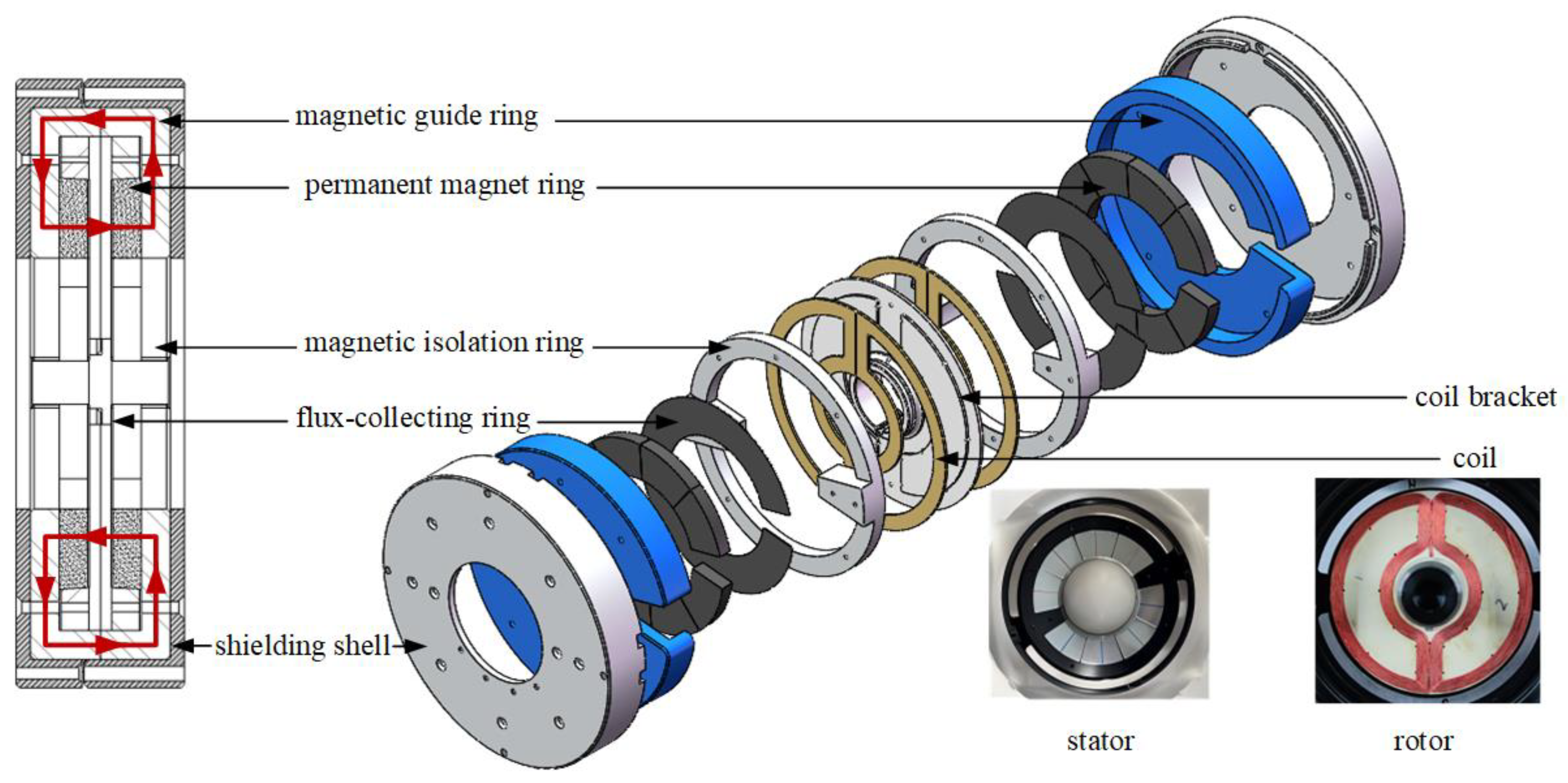
The rotating magnetic bearing employs a symmetrically designed structure with a rated output torque of 390 mN·m and ±5° working angle. The overall configuration is illustrated in Figure 3.
The stator assembly, serving as the stationary component of the rotating magnetic bearing, is responsible for generating the magnetic field. It consists of a magnetic guide ring, a permanent magnet ring, a magnetic isolation ring, a flux-collecting ring, and a shielding shell. The permanent magnet ring is designed as a segmented fan-shaped ring, divided into eight individual magnet segments. Uniformity of the magnetic field is enhanced through segmented magnetization and magnetic field superposition. The magnetic isolation ring features a hollow annular structure, while the magnetic guide ring is saddle-shaped.
The rotor assembly functions as the core element for torque output and motion execution in the rotating magnetic bearing. It comprises a coil bracket and four ear-shaped coils, which are symmetrically mounted on both sides of the bracket to ensure rotor balance across the entire operating range. Key structural and dimensional parameters of the rotating magnetic bearing are summarized in Table 5.
When the rotor approaches the maximum deflection angle on either side, the current is reversed and adjusted in magnitude to facilitate rotor acceleration and deceleration. When the rotor is near the equilibrium position, the system continuously delivers high-precision torque, enabling the rotating magnetic bearing to rapidly counteract disturbances caused by external vibrations. This ensures that the payload on the platform remains highly stable and maintains an ultra-quiet levitated state.

2.3. Design of Planar Lorentz Force Actuator

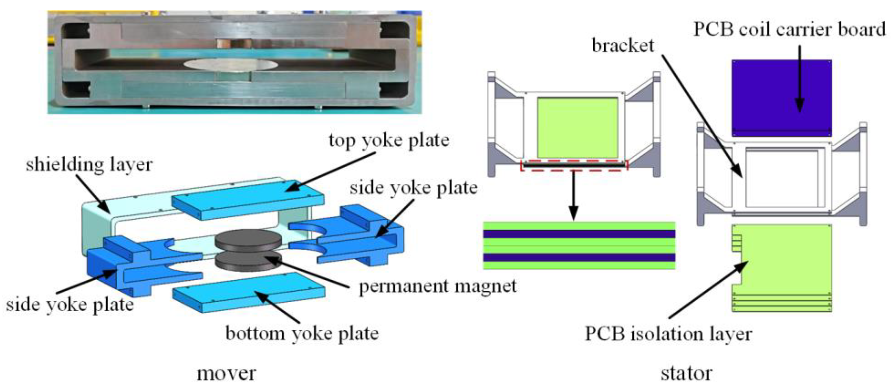
The Lorentz force actuator is designed with a symmetrical structure, featuring a rated output force of 365 mN and a working displacement of 0.5 mm. The overall configuration is illustrated in Figure 4.
The mover assembly serves as the moving component of the actuator, responsible for generating the magnetic field and undergoing Lorentz force to drive horizontal motion of the platform. It consists primarily of a permanent magnet, a top yoke plate, a bottom yoke plate, side yoke plates, and a shielding layer. The permanent magnet is cylindrical in shape and axially magnetized to minimize magnetic flux leakage. The magnet is secured between the side yoke plates, forming a symmetrical structure about the horizontal plane. A working air gap is maintained between the upper and lower sections of the magnet assembly. The shielding layer encloses the permanent magnet and yoke structure, serving both to reduce flux leakage and provide mechanical support.
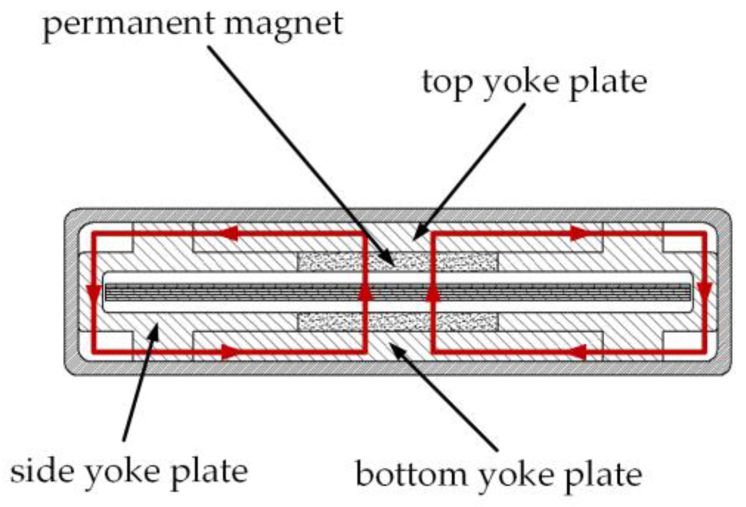
Figure 5 illustrates the magnetic circuit distribution within the mover assembly of the electromagnetic actuator. The magnetic circuit is symmetrically divided into two paths. Each path originates from the N-pole of the permanent magnet, traverses the top yoke plate, proceeds through the side yoke plates and the bottom yoke plate, and returns to the S-pole of the magnet.
As the left and right magnetic paths share the same pair of permanent magnets, the magnetic flux generated by the magnets is utilized jointly by both paths. The magnetic flux in each path is equal, and the effective area through which the flux acts is identical for both sides, i.e., ϕ1 = ϕ2 and A1 = A2. Consequently, the magnetic flux density B in the working air gap is equal for both magnetic circuits.
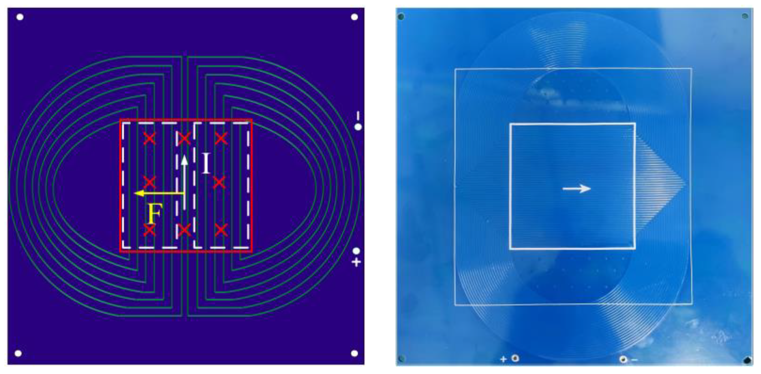
The stator assembly, serving as the stationary part of the actuator, is responsible for generating the Lorentz force. It primarily consists of a PCB coil carrier board, a PCB isolation layer, and a coil mounting bracket. The assembly includes two carrier boards and four isolation layers. Each carrier board is insulated on both upper and lower surfaces by non-metallic thin plates. The coil carrier is square in shape and features symmetrically arranged multi-turn coil traces on the left and right sides. Fixing screw holes are positioned around the periphery of the carrier board, allowing the two layers to be bolted together with spacers. The carrier incorporates orthogonally arranged spiral traces to independently control force output along the X- and Y-axes. When energized, the coils experience a Lorentz force within the magnetic field, and the corresponding reaction force drives the motion of the mover assembly.
Figure 6 illustrates the schematic and physical layout of the PCB coils in the stator assembly. The two PCB carrier boards employ different trace configurations, categorized as the horizontal-thrust coil carrier and the vertical-thrust coil carrier based on their wiring patterns. A series wiring method is adopted to ensure nearly uniform current through each coil turn in the working region, thereby improving current control accuracy. The shaded region in the diagram represents the area where magnetic flux acts, which can be further divided into effective zones corresponding to the left and right magnetic circuits, as indicated by the dashed lines. Assuming the magnetic field is directed perpendicularly into the plane of the diagram, and the white arrows denote the current direction, application of the left-hand rule demonstrates that the two PCB boards generate Lorentz forces along the X- and Y-axis directions, respectively. The mover assembly is driven by the reaction forces of these Lorentz forces to produce linear motion in both the horizontal and vertical directions.
Since the left and right magnetic circuits share the same permanent magnet and the magnetic field acting on the coils is symmetrically arranged in series, the resulting Lorentz forces are equal. This relationship is expressed as:
F 1 = n 1 B I 1 L 1 = F 2 = n 2 B I 2 L 2
where n1 and n2 represent the number of turns of the effective coil within each magnetic circuit—specifically, the number of coil turns located in the effective region of each unilateral magnetic path. Given the symmetry of the design, n1 = n2. The variable I denotes the coil current; since the coils are connected in series, I1 = I2 = I. The symbol L refers to the effective length of the coil conductor, and due to the symmetric layout, L1 = L2 = L.
The total Lorentz force F produced by a single-layer PCB carrier board can therefore be described as:
F = F 1 + F 2 = n B I L
where n is the total number of coil turns within the magnetic induction region, i.e., n = n1 + n2.
Now, consider a scenario where the actuator experiences a positive disturbance along the X-axis while at the equilibrium position, causing the mover assembly to deviate. The displacement sensor detects this deviation, and the controller converts the displacement signal into a control signal. This signal is then amplified by the power amplifier to produce a control current. When this current flows through the PCB coil carrier of the stator assembly, a Lorentz force is generated, driving the mover assembly back to its equilibrium position. Similarly, if a disturbance occurs along the Y-axis, an analogous control process restores equilibrium.
The actuator has an overall envelope size of 364 mm × 244 mm × 102.5 mm. The structural parameters of its individual components are detailed in Table 6.

2.4. Analysis of the Characteristics of the Actuator

2.4.1. Axial High-Precision Magnetic Circuit Symmetrization

The stator assembly of the rotating magnetic bearing employs a dual magnetic circuit symmetric layout to optimize circumferential magnetic field distribution and enhance torque output accuracy. Specifically, two identical fan-shaped permanent magnets are axially arranged and embedded in the magnetic ring grooves, upgrading the conventional single magnetic circuit to a dual-circuit topology. This design improves air gap magnetic field uniformity by increasing magnetic path redundancy. Furthermore, the closed centrosymmetric dual magnetic circuit is optimized to stabilize the distribution of air gap flux density.

2.4.2. Radial Regularized Wiring

The planar Lorentz force actuator utilizes multi-layer PCB coils instead of traditional wound windings, achieving high-precision and consistent coil patterns through precision etching. The flat conductor structure reduces high-frequency skin effects and avoids parasitic inductance and resistance losses inherent in hand-wound coils, improving inter-turn consistency and control accuracy. A lightweight design is implemented using high-conductivity copper foil and a polyimide substrate with a low dielectric constant, significantly reducing mass while maintaining current-carrying capacity. The specific approach involves a multi-layer stacked design: each PCB layer combines spiral and straight traces, connected in series, and vertically aligned along the Z-axis. This stacking increases winding density within a constrained space and enables independent control of different coils, supporting multi-degree-of-freedom electromagnetic actuation.

2.4.3. Series-Configured Decoupling

The two actuators in the vibration isolation platform are mechanically connected in series, simplifying the structural layout. Translational and rotational interferences are suppressed via physical isolation, achieving mechanical decoupling. In the planar actuator, a magnetic flux shielding layer is added at the edges of the permanent magnets to prevent mutual interference between the magnetic fields of the two actuators, ensuring magnetic circuit decoupling. Ultimately, this integrated approach enables full motion decoupling of the vibration isolation platform.

3. Magnetic Field Modeling and Steady-State Analysis of Two-Degree-of-Freedom Planar Lorentz Force Actuator

Based on the mechanical design and decoupling analysis of the Lorentz force magnetic levitation vibration isolation platform presented earlier, this section focuses on magnetic field modeling and steady-state performance characterization of the planar Lorentz force actuator. Through a combination of theoretical modeling and simulation validation, the distribution characteristics of the magnetic field in the air gap are investigated, and the magnetization length of the permanent magnet is optimized. These results provide a theoretical foundation for subsequent analysis of the system’s coupled dynamic behavior.

3.1. Establishment and Analysis of Magnetic Circuit Model Based on Equivalent Magnetic Circuit Method

Based on the magnetic circuit configuration illustrated in Figure 5, the actuator’s magnetic structure is simplified into a parallel magnetic circuit model using the equivalent magnetic circuit method, as depicted in Figure 7. This approach allows for a more systematic analysis of magnetic flux distribution and the influence of key parameters on the system’s steady-state performance.
According to the symmetrical structure of the actuator, Ru1 = Ru2, Rl1 = Rl2, the parallel magnetic circuit can be converted into a series magnetic circuit, as shown in Figure 8.
φ1 and φ2 denote the magnetic flux in the left and right air-gap magnetic circuits, respectively. The magnetomotive forces of the upper and lower permanent magnets are represented as Fpm1 and Fpm2, with their corresponding reluctances denoted as Rpm1 and Rpm2. The reluctance of the air gap is Rg, while Ru1 and Ru2 represent the reluctances of the upper yoke plates, Rs is the reluctance of the yoke side plate, and Rl1, Rl2 correspond to the reluctances of the lower yoke plates.
Due to the symmetrical design of the actuator, the following equalities hold:
Ru1= Ru2, Rl1= Rl2
This symmetry allows the parallel magnetic circuit to be equivalently transformed into a series magnetic circuit, as illustrated in Figure 8. The transformation simplifies the analysis while preserving the physical behavior of the system.
The closed magnetic circuit can be mathematically expressed through the relationship between magnetic reluctance and magnetomotive force (MMF) as follows:
( R p m 1 + R a l l + R p m 2 + R g ) ϕ = F p m 1 + F p m 2
The upper and lower permanent magnets, constructed from NdFeB material, generate magnetomotive forces Fpm1 and Fpm2, respectively, expressed as:
F p m 1 F p m 2 = H c 1 H c 2 l p m 1 l p m 2
In the formulation, Hc denotes the coercivity of the permanent magnet, and lpm represents its magnetization length. Neglecting demagnetization effects and manufacturing tolerances, it follows that Hc1 = Hc2 and lpm1 = lpm2. Under these conditions, the magnetic flux density Bg acting on the coil can be derived as follows:
B g = ϕ S g = 2 H c l p m ( 2 R p m + R g + R a l l ) S g
where Sg is the cross-sectional area of the permanent magnet, that is, the cross-sectional area of the working air gap. Meanwhile, Rall represents the total reluctance of the magnetic yoke assembly. The expression for Rall is given by:
R a l l = 1 1 R u 1 + R s + R l 1 + 1 R u 2 + R s + R l 2
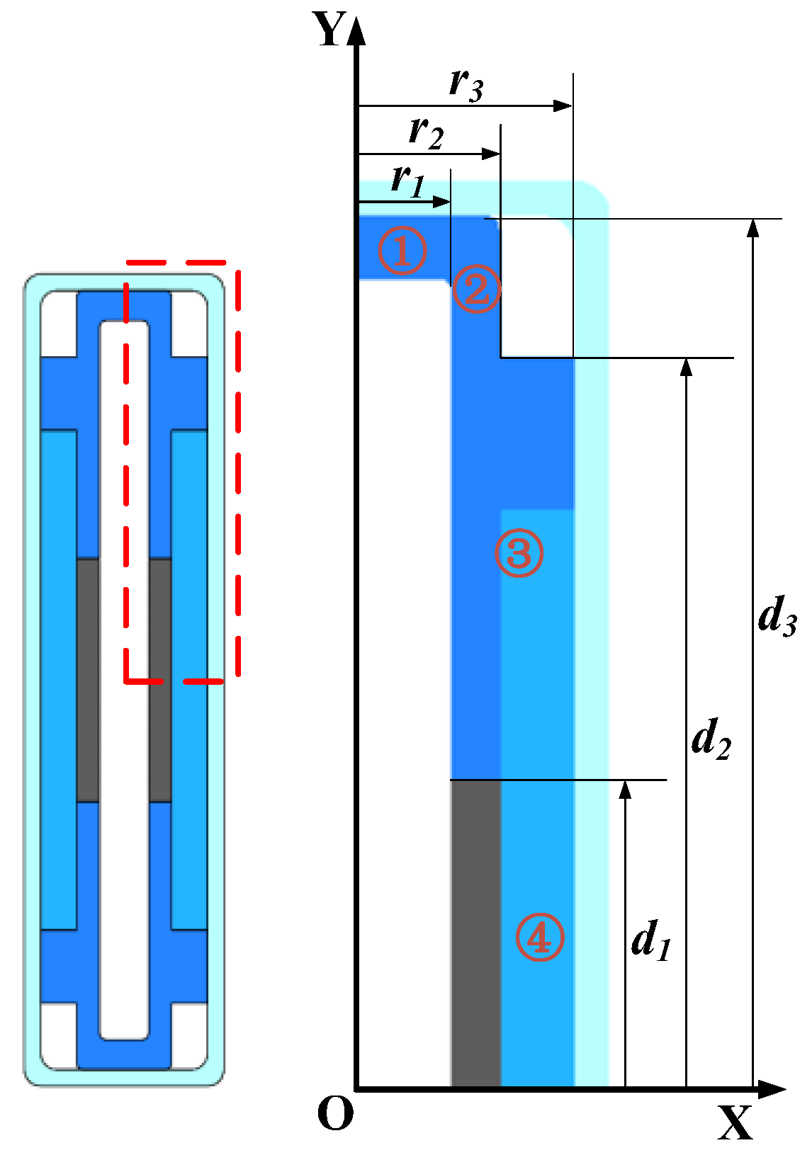
Based on numerical computation of the reluctance values across different regions of the actuator, the complex geometry of the yoke and the presence of shared magnetic pathways necessitate a segmented approach to structural analysis. As illustrated in Figure 8, the cross-section of the actuator is divided into discrete regions, and a relative coordinate system is established for each effective zone to facilitate precise modeling and calculation.
This methodology enables accurate quantification of magnetic reluctance in irregularly shaped components and ensures consistent treatment of common magnetic paths within the assembly.
In the Figure 9, d1 is the radius of the permanent magnet, d2 is the distance from the center of the permanent magnet to the top of the lower part of the yoke side plate, d3 is the distance from the center of the permanent magnet to the top of the yoke side plate, r1 is the distance from the center of the working air gap to the inside of the yoke side plate, r2 is the distance from the center of the working air gap to the outside of the yoke side plate, and r3 is the distance from the center of the working air gap to the outside of the yoke roof.
The working air gap reluctance Rg is:
R g = l g μ 0 S g = 2 r 1 μ 0 S g
where lg is the working air gap length, μ0 is the air permeability.
The magnetic steel reluctance Rpm is:
R p m = r 2 r 1 μ 0 μ r S g
The part of the yoke shown in Figure 8 can be divided into four regions, and its magnetoresistance Ryoke can be expressed as:
R y o k e = 1 4 l y o k e μ y o k e S y o k e = r 2 r 1 μ y o k e S y o k e 1 + d 3 d 2 μ y o k e S y o k e 2 + d 2 d 1 μ y o k e S y o k e 3 + r 3 r 2 μ y o k e S y o k e 4
where lyoke is the equivalent length of each part in the magnetic circuit, μyoke is the permeability of 1J22, and Syoke is the cross-sectional area of each part of the yoke in the magnetic circuit.
By substituting Equations (7)–(9) into Equation (5), the magnetic flux density Bg in the air gap can be derived as follows:
B g = ϕ S g = 2 H c l p m 2 ( r 2 r 1 ) μ 0 μ r S g + 2 r 1 μ 0 S g + 4 ( r 2 r 1 μ y o k e S y o k e 1 + d 3 d 2 μ y o k e S y o k e 2 + d 2 d 1 μ y o k e S y o k e 3 + r 3 r 2 μ y o k e S y o k e 4 ) × 1 S g
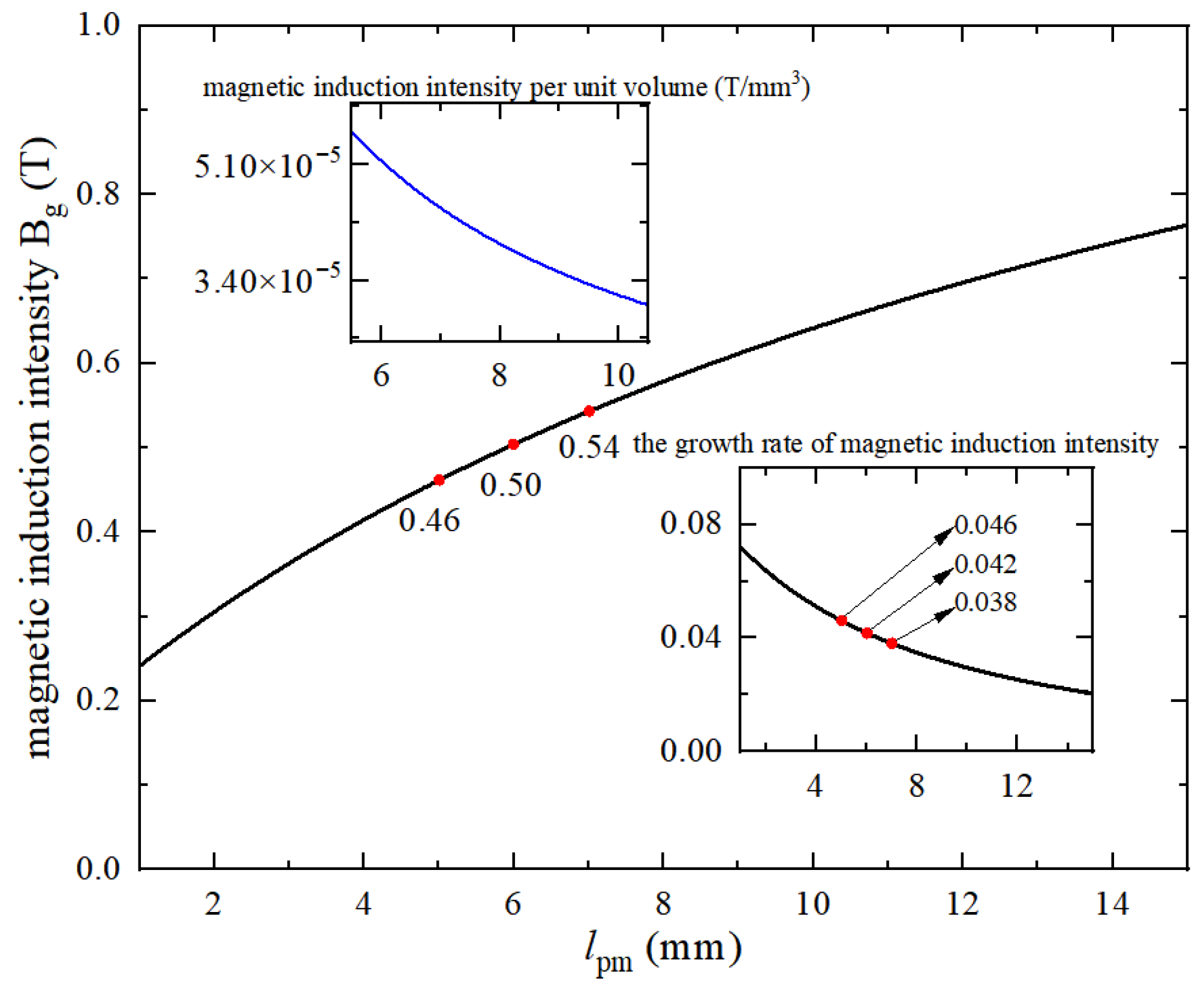
Due to the high permeability of the yoke material (μyokeμrμ0), the magnetic induction intensity Bg in the air gap is primarily governed by the combined effects of the permanent magnet reluctance Rpm and the air-gap reluctance Rg, to which it is inversely proportional. Further analysis reveals that Rpm and Rg are determined by the magnetization length lpm of the permanent magnet and the air-gap length lg, respectively. Consequently, Bg is approximately proportional to the ratio lpm/lg. Considering practical requirements and structural constraints, this ratio should be minimized while maintaining sufficient magnetic induction intensity. With the designed air-gap length set to lg = 15 mm, the specific relationship between Bg and lpm is illustrated in Figure 10, providing a basis for optimizing the magnetic performance.

3.2. Establishment and Analysis of Magnetic Field Equivalent Current Model Based on Maxwell’s Principle

To accurately quantify the spatial distribution of the magnetic field and improve computational precision, an equivalent current model is established for the magnetic field analysis. The permanent magnet possesses a residual magnetization along its magnetization direction, which can be conceptually represented as the presence of an equivalent molecular current within the material. This molecular current accounts for the macroscopic magnetic behavior exhibited by the permanent magnet. The molecular current can be understood as a microscopic ring current that is equivalent to the magnetic moment of atoms or molecules within a permanent magnet. When the material is magnetized, the orientations of these microscopic currents become aligned. Their collective effect is macroscopically equivalent to a surface current flowing on the exterior of the permanent magnet.
When the magnetization intensity M is uniform throughout the permanent magnet, the internal molecular currents cancel each other, while the surface molecular currents remain. The surface current density Js of the permanently magnetized material with magnetization intensity M is given by:
J = M × n
where n is the unit vector of the normal direction of the permanent magnet surface. When the magnetization inside the magnet is not uniform, there is an internal molecular current density Ji of:
J i = × M
According to the Biot–Savart law, the magnetic flux density B at any point in space generated by a steady current can be expressed as:
B = μ 0 4 π ( J i × r r 3 d V + J × r r 3 d S )
Figure 11 is the magnetic field distribution diagram represented by the equivalent current method. Suppose that the permanent magnet is uniformly magnetized, the magnetization is along the Z-axis direction, the magnetization intensity M is a constant vector, the current density is JS, P (x, y, z) is a point in space, Q (x0, y0, z0) is a point on the permanent magnet, and the molecular current element at Q is Idldz. The magnetic induction intensity Bp of the space point P can be obtained as follows:
d B p = μ 0 4 π I d l d z r 3 × r
The dl at the Q point is:
d l = R 1 cos α d α i + R 1 sin α d α j
The vector relationship r is:
r = x x 0 i + ( y y 0 ) j + ( z z 0 ) k = R 1 cos α R 2 cos β i + ( R 2 sin β R 1 sin α ) j + ( z z 0 ) k
By substituting Equations (15) and (16) into Equation (14), the magnetic flux density Bp at the midpoint Pin space can be derived through integration as follows:
B p = μ 0 I R 1 4 π 0 2 π d α 0 z ( z z 0 ) sin α r 3 i + ( z 0 z ) cos α r 3 j + R 2 sin ( α + β ) r 3 k d z
Equation (18) represents the spatial magnetic field distribution model for a single cylindrical permanent magnet. To extend this model to the Lorentz force actuator, an equivalent current model is constructed as illustrated in Figure 12. The magnetic flux density Bg at any point within the working air gap of the actuator can be expressed as:
B g = μ 0 I 1 R 1 4 π 0 2 π d α 0 z z sin α r 3 i z cos α r 3 j R 2 sin ( α + β ) r 3 k d z + μ 0 I 2 R 3 4 π 0 2 π d γ 0 z ( z l g ) sin γ r 3 i + ( l g z ) cos γ r 3 j + R 2 sin ( β γ ) r 3 k d z
Ignoring the machining error and local demagnetization of the permanent magnet, it can be seen that the equivalent current I1 = I2, and the radius of the permanent magnet R1 = R2.
Given the actuator’s PCB coil current I, the total effective conductor length L, and the number of coil turns N, the output Lorentz force F can be expressed as:
F = N B g , z I L

3.3. Finite Element Simulation Analysis

Based on the key parameters of the actuator, two-dimensional and three-dimensional models were constructed using finite element analysis software maxwell, incorporating critical components such as permanent magnets, coils, and yokes. The magnetic flux density and spatial distribution of the magnetic field within the working air gap of the equivalent model were investigated under varying magnetization lengths.
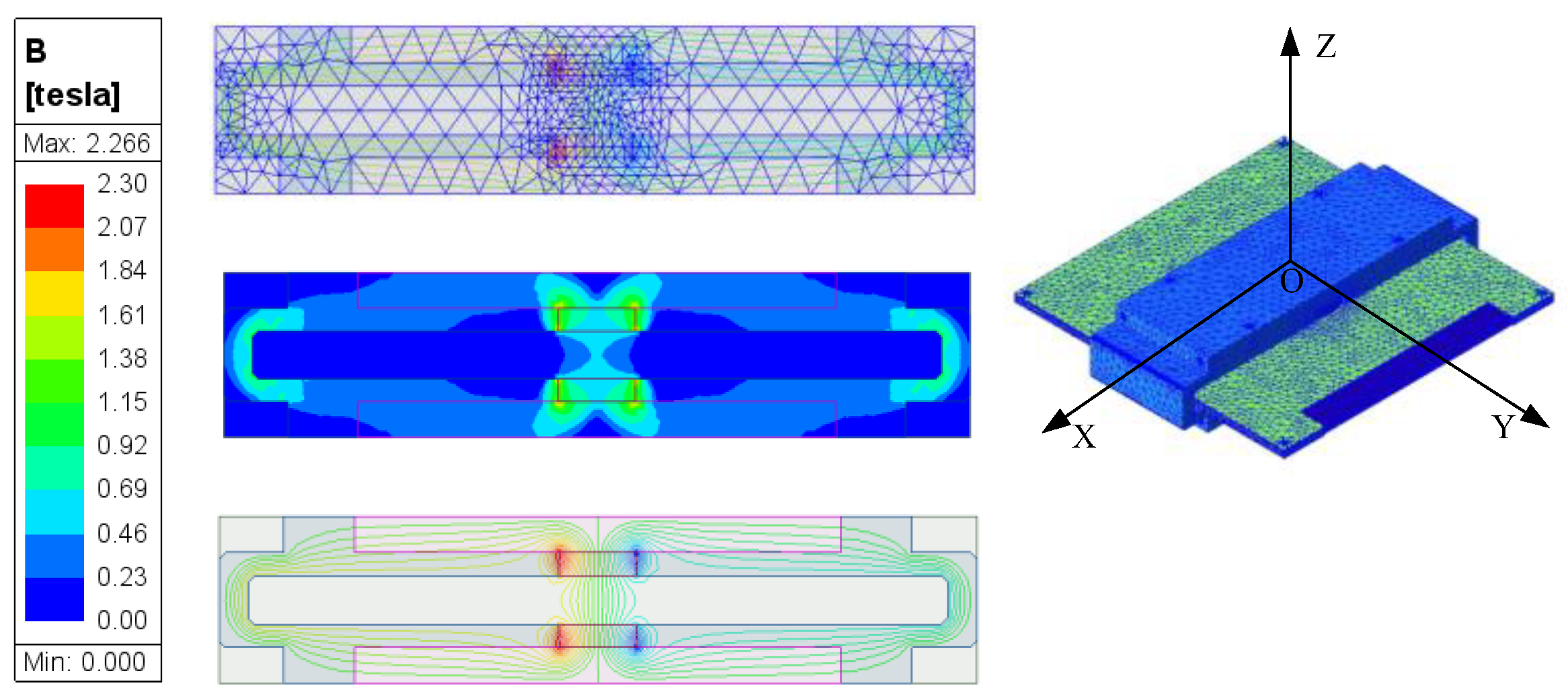
To minimize analysis errors and enhance both simulation accuracy and computational efficiency, the actuator was subdivided into distinct regions with tailored mesh strategies. Local mesh refinement was specifically applied in the air gap region to capture field variations with higher precision. The mesh for the magnetic circuit region was set to 0.5 mm, with a local refinement to 0.1 mm in the air gap. The resulting finite element model is illustrated in Figure 13.
To investigate the influence of magnetization length on the air-gap magnetic field, a parametric sweep was conducted based on theoretical results derived from the equivalent magnetic circuit method. The magnetization length Lm was varied from 5.0 mm to 10.0 mm in increments of 0.5 mm, resulting in 11 distinct simulation cases. Figure 14 displays the magnetic flux density contour plot and vector distribution under typical operating conditions, illustrating the spatial variation and directionality of the magnetic field for representative configurations.
Analysis of the magnetic flux density contour and vector diagrams reveals that the magnetic circuit exhibits a symmetric dual-path distribution between the left and right sides. The magnetic field is generated exclusively by the permanent magnets, with field lines forming closed loops through the permanent magnets, yoke top plate, and yoke side plates. The magnetic flux amplitudes on both sides are nearly identical, confirming the effectiveness of the symmetric structural design. However, edge effects and flux leakage are observed near the corners where the yoke top and side plates meet, accompanied by divergent magnetic field lines. This behavior underscores the importance of incorporating a magnetic shielding layer in the structural design, as previously proposed, to mitigate flux leakage and enhance magnetic efficiency.
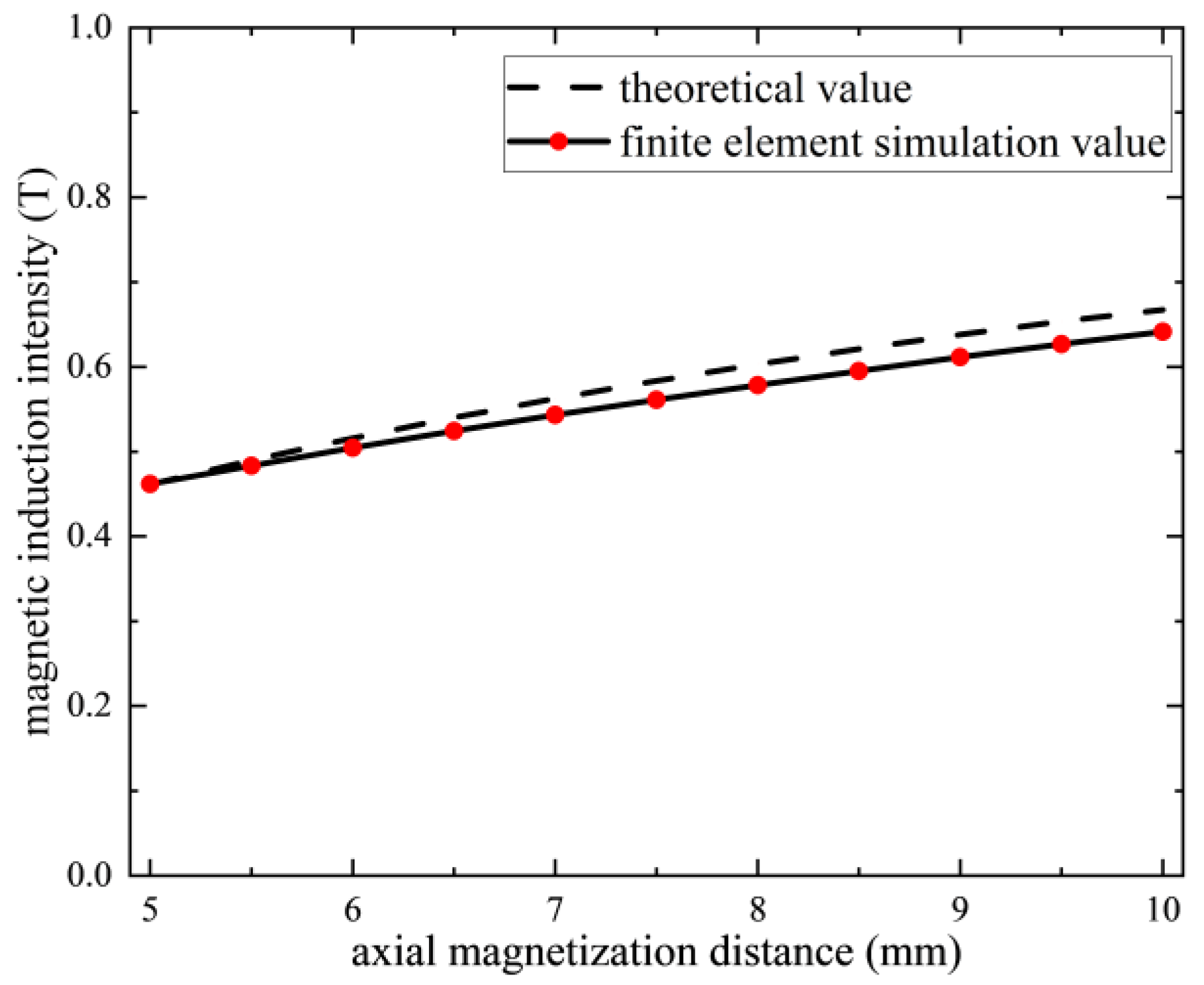
A parametric analysis of the system was conducted to evaluate the influence of magnetization length on the magnetic field characteristics. To validate the accuracy of the model, theoretical values obtained from the equivalent magnetic circuit method were compared with finite element simulation results, as illustrated in Figure 15.
As shown in the diagram, the two sets of results exhibit strong agreement when the magnetization length is small, with a maximum relative error of only 1.3%. As the magnetization length increases, the relative error gradually rises, reaching a maximum value of 4.1%. The growing discrepancy with increased magnetization length is attributed to the heightened influence of flux leakage and fringing effects, which are more accurately modeled in the simulation than in the idealized theoretical framework.
To analyze the magnetic field characteristics and evaluate the control accuracy of the actuator, the mean magnetic flux density B ¯ and the magnetic field uniformity ξ are defined as key metrics. The mean value B ¯ reflects the actuator’s power efficiency: a higher B ¯ reduces the required current for a specified output force, thereby lowering power consumption. The uniformity ξ, quantitatively defined by Equation (20) as:
ξ = 1 1 n i = 1 n B i B ¯ 2 B ¯
The uniformity of the magnetic field produced by varying magnetizing lengths within the working air gap was systematically compared and analyzed, with axial magnetic flux density distribution data collected for each configuration. As depicted in Figure 16, the simulation results reveal that the magnetic field distribution can be delineated into three distinct regions based on its spatial characteristics. These regions reflect changes in field strength and consistency, illustrating the impact of magnetizing length on the overall magnetic performance and providing critical insight into the actuator’s efficiency and control precision.
As shown in the figure, when the magnetization length is less than 6 mm, the magnetic flux density remains below 0.5 T, which fails to meet the basic performance requirements of the actuator. When the magnetization length exceeds 8 mm, although the magnetic flux density becomes sufficient, both the cost and the volume of the permanent magnet increase noticeably, adversely affecting the dynamic response characteristics of the actuator.
A magnetization length between 6 mm and 8 mm offers an optimal balance, providing not only adequate magnetic performance but also favorable economic efficiency. In particular, at a magnetization length of 7 mm, the magnetic field uniformity reaches 99.91%, and the average magnetic flux density is 0.56 T, exceeding the theoretical value by 12% and demonstrating beneficial redundancy for operational reliability.
The circumferential distribution of magnetic flux density under the 7 mm magnetization length condition was further analyzed. Simulation results were used to validate the circumferential magnetic field distribution characteristics at various points within the air gap, as predicted by the equivalent current method. Three circumferential paths—D1, D2, and D3, spaced 3.75 mm apart—were defined within the air gap, with 1000 sample points selected along each path. Using finite element analysis software, the variation in magnetic flux density along the Z-axis was computed for each point, as illustrated in Figure 17.
As indicated by the results, the magnetic flux density distributions along paths D1 and D3 are nearly identical, confirming the fundamental symmetry of the magnetic circuit. The average magnetic flux density for both D1 and D3 is 0.548 T, with corresponding magnetic field uniformities of 99.37% and 99.45%, respectively. Path D2, located at the center of the air gap, exhibits the highest magnetic flux density, with an average value of 0.559 T and a uniformity of 99.23%. The variation in average flux density across the three paths is minimal, dominated by the central region (D2). The relative rate of change between D1 and D3 is merely 2%, and the magnetic field uniformity remains consistently above 99% throughout the air gap, demonstrating exceptional spatial consistency and structural optimization.

4. Dynamic Coupling Characteristics Analysis and Vibration Isolation Verification of Maglev Active Vibration Isolation Platform

The vibration isolation platform employs a series of three-degree-of-freedom (3-DOF) structures. While this configuration reduces mechanical complexity, it introduces coupling effects—primarily manifested as kinematic interference between the two actuators across multiple degrees of freedom. Building upon the static magnetic field modeling and steady-state analysis of the planar Lorentz force actuator, this section focuses on investigating the dynamic coupling characteristics of the integrated active vibration isolation platform. A dynamic equation of the platform is established to elucidate the interaction mechanism between translational and rotational motions under the series mechanical layout, thereby providing theoretical support for subsequent high-precision active control.

4.1. Mechanism of Mechanical-Magnetic Coupling

In the mechanically series-configured layout, where the rotating magnetic bearing and the planar actuator are connected in series, dynamic coupling effects arise between the translational and rotational degrees of freedom. Specifically, displacements along the X or Y axis may induce torque fluctuations around the Z-axis, while rotations about the Z-axis can cause asymmetry in the air gap of the planar actuator, leading to nonlinearities in the Lorentz force output. Since the stator components of both actuators are mounted on a common frame, their dynamic responses exhibit mutual interference.
This coupling manifests as translational-rotational cross-interference, wherein displacements in the X/Y directions generate unintended torque, resulting in angular drift around the Z-axis, as well as a rotation-translation reverse effect, whereby Z-axis rotation disrupts air gap symmetry and introduces nonlinear distortions in the translational force output. These interactions underscore the necessity of integrated dynamic modeling and decoupling control strategies to mitigate cross-coupling effects and ensure high-precision performance of the vibration isolation system.

4.2. Mathematical Modeling of Coupling Effect

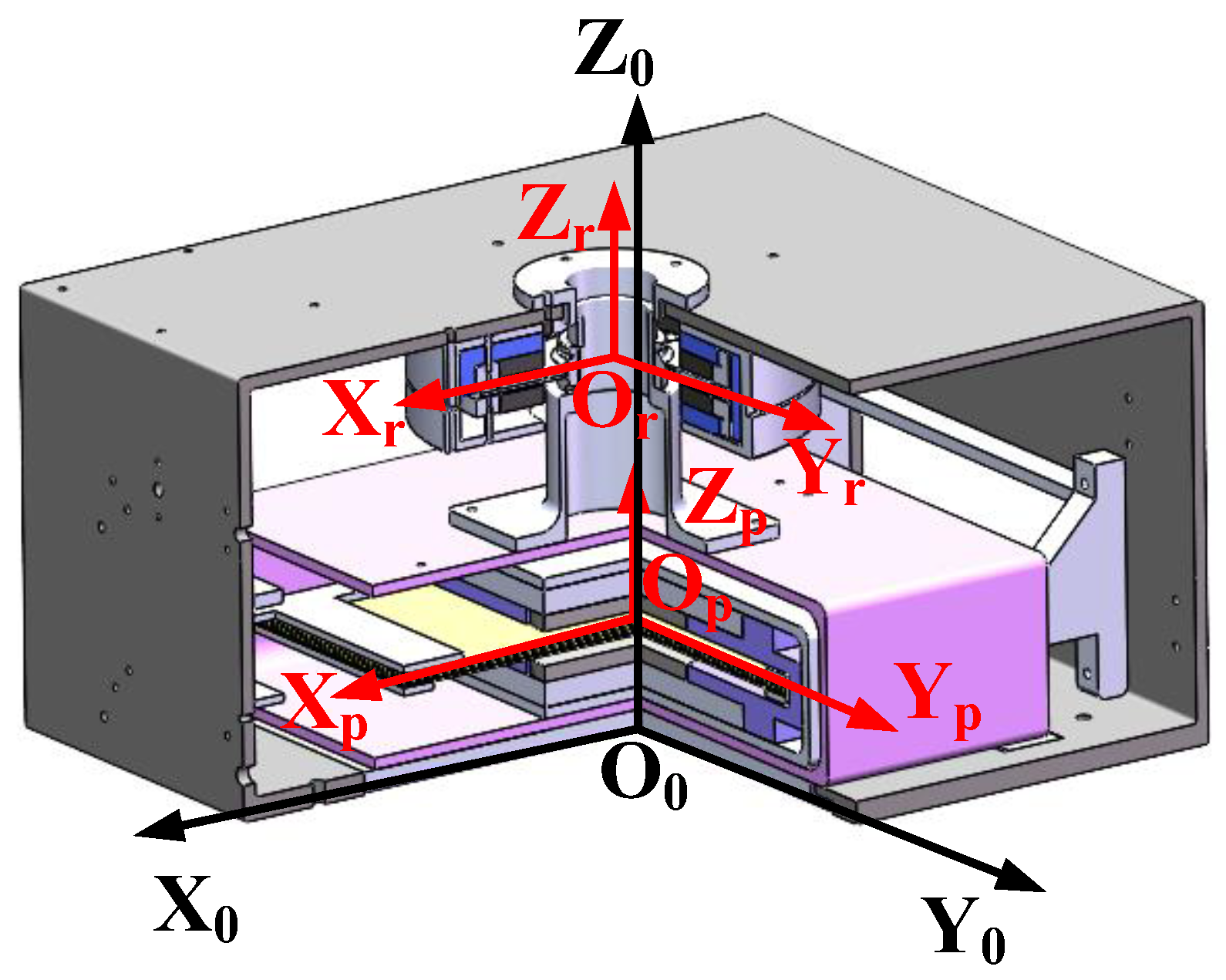
To facilitate the analysis, the coordinate system illustrated in Figure 18 is established, comprising three distinct reference frames:
Frame Coordinate System O0-X0Y0Z0: Fixed to the base of the overall structure, with its origin at the center of the frame’s bottom surface. This system describes the platform’s global motion.
Translational Coordinate System Op-XpYpZp: Attached to the mover assembly of the planar actuator, with its origin at the center of the air gap. It characterizes the translational motion and Lorentz force output of the planar actuator. The axes Xp, Yp, and Zp remain aligned with the frame system axes X0, Y0, and Z0 at all times.
Rotational Coordinate System Or-XrYrZr: Centered at the rotational axis of the magnetic bearing, used to describe its rotation and magnetic field distribution. The Zr-axis remains coincident with Z0, while the Xr- and Yr-axes are initially aligned with the frame system but rotate with the bearing.
Due to the consistent alignment of Xp, Yp, Zp with X0, Y0, Z0, and the fixed orientation of Zr relative to Z0, the dynamic equations of the non-inertial coordinate systems (translational and rotational) maintain invariant projections onto the frame coordinate system. This geometric consistency simplifies the modeling of coupled dynamics and supports subsequent control design.
Let X and Y axis displacements be x and y, respectively. In the translational coordinate system, the motion equation of the planar actuator is as follows:
m x ¨ + c x x ˙ = F x + F d x m y ¨ + c y y ˙ = F y + F d y
where cx and cy are translational damping coefficients, Fdx and Fdy are disturbing forces.
According to Equation (19), the two-degree-of-freedom output Lorentz force can be expressed as:
F x = F y = N B I L = N μ 0 I 1 R 1 I L 4 π 0 2 π d α 0 z z sin α r 3 i z cos α r 3 j R 2 sin α + β r 3 k d z + N μ 0 I 3 R 3 I L 4 π 0 2 π d γ 0 z + z l g sin γ r 3 i + l g z cos γ r 3 j R 2 sin β γ r 3 k d z
Let the Z-axis rotation angle be, in the rotating coordinate system, the rotation equation of the rotating magnetic bearing is:
J z θ ¨ z + c θ θ ˙ z = T z + T d
where cθ is the rotational damping coefficient, Td is the interference torque.
Considering the coupling effects and assembly errors between translational and rotational dynamics, translational displacements x and y may induce an additional torque Txy, which can be expressed as:
T x y = F x r y + y + F y r x + x
where rx and ry are assembly installation errors, and the rotation angle will produce air gap asymmetric force, which is expressed as follows:
F m a g , x = k x θ θ z F m a g , y = k y θ θ z
Building upon the single-degree-of-freedom Lorentz force output model, the three-degree-of-freedom coupled dynamic equation of the platform is established by integrating translational, rotational, and coupling terms as follows:
m x ¨ + c x x ˙ + k x θ θ z = F x + F d x m y ¨ + c y y ˙ + k y θ θ z = F y + F d y J z θ ¨ z + c θ θ ˙ z F x r y + y + F y r x + x = T z + T d
Owing to the symmetrically designed series structure of the platform and the previously validated high uniformity of the magnetic field in the working air gap, along with the assumption of negligible assembly and installation errors, Equation (26) can be simplified to:
m x ¨ + c x x ˙ + k x θ θ z = F x + F d x m y ¨ + c y y ˙ + k y θ θ z = F y + F d y J z θ ¨ z + c θ θ ˙ z F x y + F y x = T z + T d

4.3. Coupling Effect Simulation and Vibration Isolation Verification

To validate the accuracy of the mechano-magnetic coupling model, quantify the dynamic coupling effects between translational and rotational motions, and evaluate the vibration isolation performance, the displacement and angular responses of the platform under coupled conditions are analyzed for different input signals. Given the focus on low-frequency vibration isolation, sinusoidal displacement disturbances and sinusoidal angular displacement disturbances are applied to the translational and rotational degrees of freedom, respectively, to simulate typical space environment vibrations. Owing to the symmetry of the actuator about the X = Y plane, the system’s response to vibration interference along the Y-axis is identical to that along the X-axis. Therefore, the study concentrates exclusively on the X-axis translational direction and the Z-axis rotational direction, ensuring efficient analysis without loss of generality. This approach allows for a comprehensive assessment of the platform’s decoupling capability and isolation effectiveness under representative dynamic excitations.
A sinusoidal excitation with an amplitude of 0.001 m was applied to the planar actuator. The disturbance signal had an initial phase of 0 and frequencies of 3 Hz, 5 Hz, and 10 Hz, respectively. The resulting Z-axis angular drift output is shown in Figure 19.
As shown in Figure 18, when subjected to interference frequencies of 3 Hz, 5 Hz, and 10 Hz, the resulting Z-axis angular drifts are 9.14 × 10⁻⁶ rad, 1.2 × 10⁻⁶ rad, and 2.2 × 10⁻⁷ rad, respectively. These values are significantly smaller than the amplitude of the translational input excitation, demonstrating that the cross-coupling gain from translation to rotation is very low.
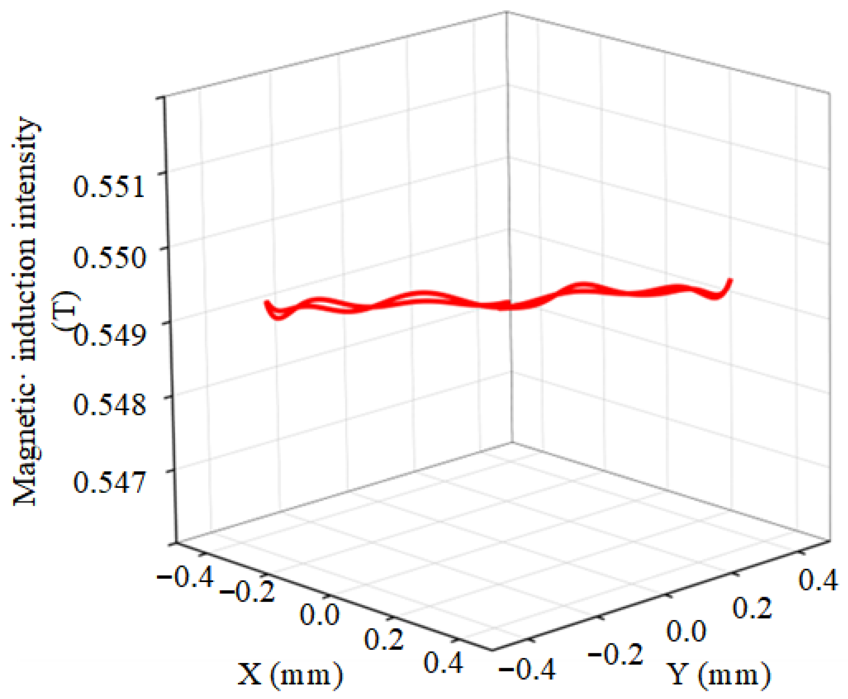
Based on the mechanical structure analysis of the platform, the maximum allowable rotation angle is determined to be ±3°. To account for manufacturing and assembly tolerances, a fixed deflection state of θz = 5° is applied. Under this condition, low-frequency sinusoidal excitations are separately applied along the X and Y directions, and the resulting magnetic field distribution in the air gap is illustrated in Figure 20.
As shown in Figure 19, the magnetic flux density in the air gap remains largely unchanged, with a periodic distribution pattern and values consistently around 0.5493 T. The calculated magnetic field uniformity reaches 99.8%, indicating that under small-angle rotations, the air gap magnetic field stability is effectively maintained through the dual mechanisms of small-angle linearization approximation and symmetric magnetic circuit compensation.
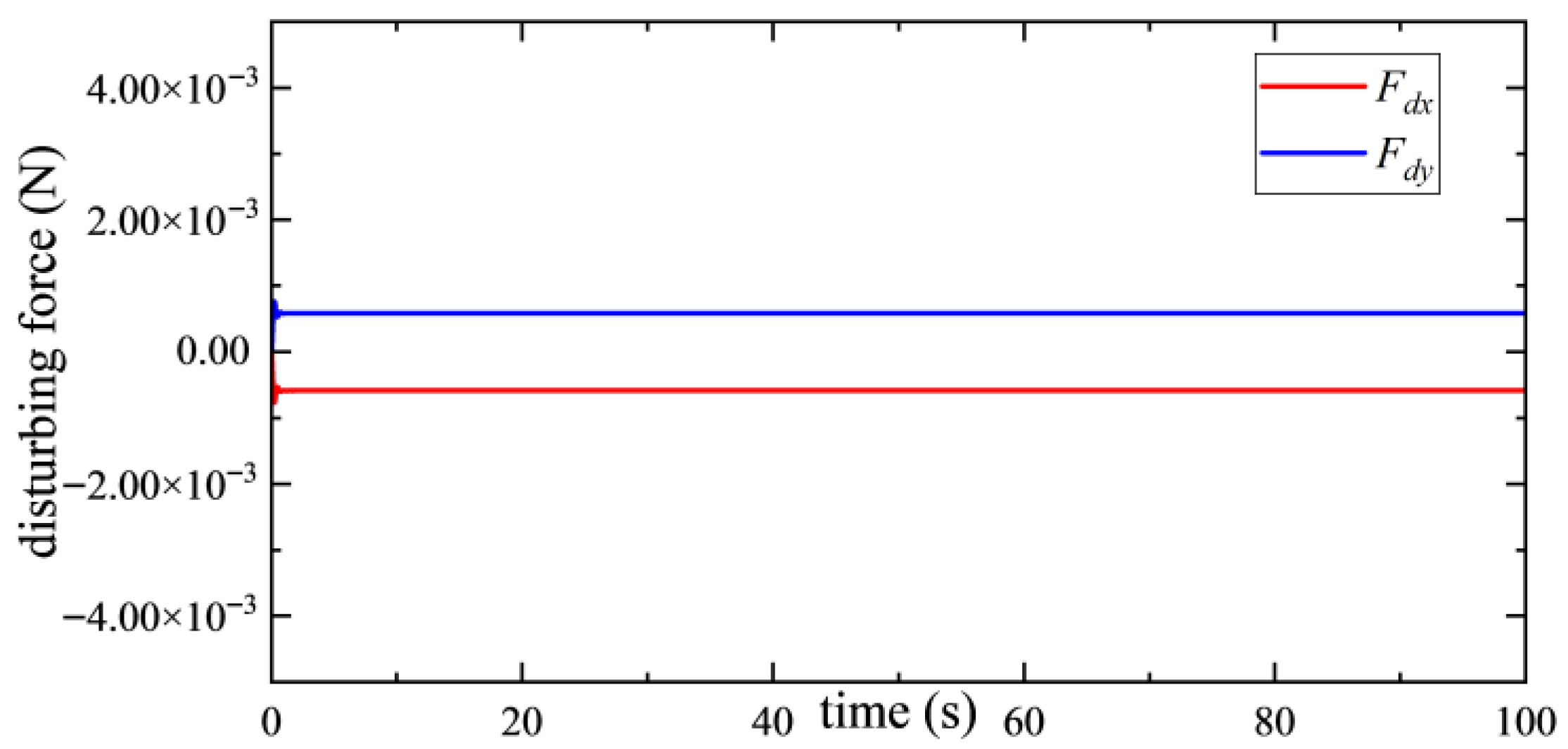
To simulate pointing stability tests in a micro-vibration environment, step signals were applied along the X and Y directions under a deflected state of θz = 5°. The resulting planar disturbance forces and output forces are shown in Figure 21 and Figure 22, respectively, providing insight into the platform’s dynamic response and control performance under realistic operational conditions.
As observed in Figure 21, under small-angle rotation conditions, the magnitude of the interference force induced by rotational coupling is three orders of magnitude smaller than the applied excitation force. This result further confirms the effectiveness of the symmetric magnetic circuit design and the compensation mechanism in minimizing cross-coupling effects, thereby ensuring high-precision force output and stable performance of the vibration isolation platform even in deflected operational states.
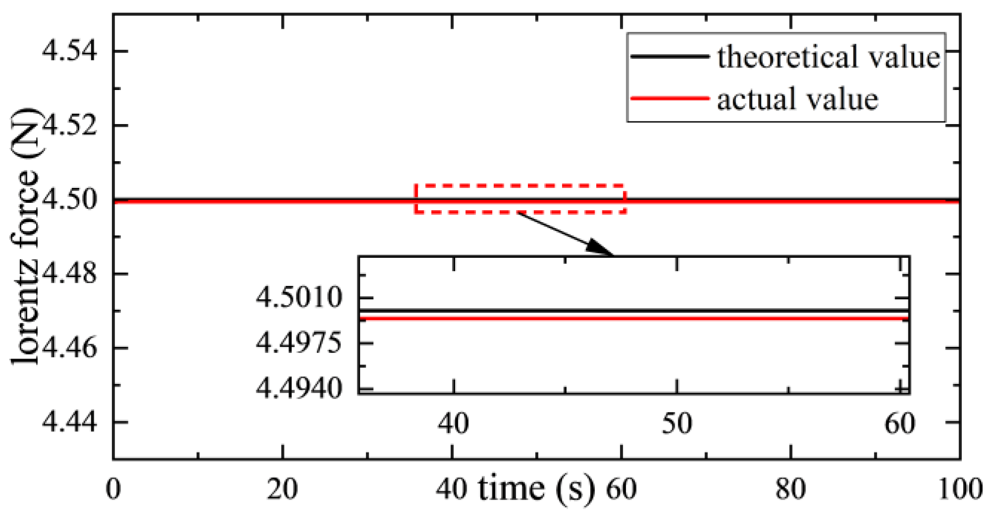
As shown in Figure 22, the output Lorentz force in the translational single degree of freedom closely matches the theoretical value, with a deviation of only 0.01%. This indicates that the control performance in the translational direction remains highly accurate and is not significantly affected by the rotational degree of freedom, demonstrating that the reverse coupling from rotation to translation is negligible.
To address the challenges associated with model coupling, external vibration disturbances, and model uncertainties, a control strategy integrating feedforward decoupling with active disturbance rejection control (ADRC) is employed. The extended state observer (ESO) within the ADRC framework is utilized to estimate and compensate for the total disturbance in the system in real time. Combined with feedforward decoupling, this approach constitutes a composite control architecture. The overall control structure is illustrated in Figure 23.
The optimal control instruction F c m d needs to be found such that:
u x u y T x T y = u T = u c m d 0 = B   F c m d = 1 0 0 1 0 r 3 r 3 0 F c m d
u c m d is the expected control force. Since Equation (28) is an overdetermined system of equations, there is no exact solution, and only the optimal solution under the least squares can be calculated, that is, find F c m d to minimize the following objective function, and finally obtain:
F c m d = F x , c m d F y , c m d = B + u x , c m d u y , c m d 0 0 = 1 1 + d 2 1 0 0 r 3 0 1 r 3 0 u x , c m d u y , c m d 0 0 = 1 1 + d 2 u x , c m d u y , c m d
Feedforward decoupling is designed based on an ideal system model. However, actual systems are subject to model uncertainties, external disturbances, and complex dynamic couplings. The role of Active Disturbance Rejection Control (ADRC) is to estimate and compensate for these collective disturbances, thereby generating the required control force command u c m d .
To account for the total disturbance, the translational dynamics of the system are reformulated. Taking the X-direction as an example, the controlled equation of motion can be expressed as:
x ¨ = f x x ˙ , x , y ˙ , y , θ ˙ x , θ x , θ ˙ y , θ y , ω x t + b x u x
In Equation (30), ω x t is the external disturbance, b x is the control gain, and u x is the expected control force of the system.
Using ESO to expand the state of the system, a new state variable is defined for the X channel:
z 1 = x z 2 = x ˙ z 3 = f x
Suppose that the dynamic characteristics of f x are unknown, but can be expressed as z ˙ 3 = h x t , where h x t is unknown but bounded.
Similarly, the state of Y channel is expanded:
z 4 = y z 5 = y ˙ z 6 = f y
Since the states of Rx and Ry (rotation angles θ x and θ y ) are measurable quantities and are also taken as the states of the system, the extended state vector of the whole system is:
Z = z 1 , z 2 , z 3 , z 4 , z 5 , z 6 , z 7 , z 8 T = x , x ˙ , f x , y , y ˙ , f y , θ x , θ y T
Based on the above definition, the state space model of the expanded system is established:
z ˙ 1 = z 2 z ˙ 2 = z 3 + b x u x z ˙ 3 = h x t z ˙ 4 = z 5 z ˙ 5 = z 6 + b y u y z ˙ 6 = h y t z ˙ 7 = ω x z ˙ 8 = ω y
The corresponding continuous state space equation is:
Z ˙ = A e Z + B e u + E e h t
In Equation (35), E e is the disturbance input matrix, which is the unit matrix, h t is the disturbance vector, which represents all unmodeled dynamic and external disturbances, A e is the coefficient matrix, and B e is the control input matrix. The specific form is as follows:
A e = 0 1 0 0 0 0 0 0 0 0 1 0 0 0 0 0 0 0 0 0 0 0 0 0 0 0 0 0 1 0 0 0 0 0 0 0 0 1 0 0 0 0 0 0 0 0 0 0 0 0 0 0 0 0 0 0 0 0 0 0 0 0 0 0 , B e = 0 0 b x 0 0 0 0 0 0 b y 0 0 0 0 0 0
The observation equation of the system is:
Y = C e Z = x , y , θ x , θ y T = z 1 , z 4 , z 7 , z 8 T
Based on Equation (36), a nonlinear extended state equation is constructed:
Z ^ ˙ = A e Z ^ + B e u + L Φ e , k , σ
In Equation (37), L is the observer gain matrix, which determines the convergence speed and anti-noise performance of the state estimation, and Φ e , k , σ is an improved nonlinear function. Compared with the nonlinear function fal e , α , δ commonly used in ADRC, it can achieve global smoothness and avoid introducing high-frequency micro-amplitude jitter. The specific forms are as follows:
Φ e , k , σ = shg e , k , σ = k e 1 + e σ 1 / σ
In Equation (38), k is the maximum gain, which directly correlates the observer’s ability to suppress large disturbances, and σ is a nonlinear shape factor, which determines the smoothness and speed of the control function transition from the linear region to the saturation region.
The discrete state update equation is obtained by the forward Euler method:
Z ^ k + 1 = Z ^ k + T s A e Z ^ k + B e u k + L d Φ e k
Using the estimated value Z ^ of the system expansion state vector output by ESO, combined with the control gain b x and b y , the final control quantity is obtained:
u x , c m d = u x 0 f ^ x b x = u x 0 z ^ 3 b x u y , c m d = u y 0 f ^ y b y = u y 0 z ^ 6 b y
The feedforward decoupling module utilizes the feedback signal u c m d = u x , c m d ,   u y , c m d T to compute the actuator command F cmd .
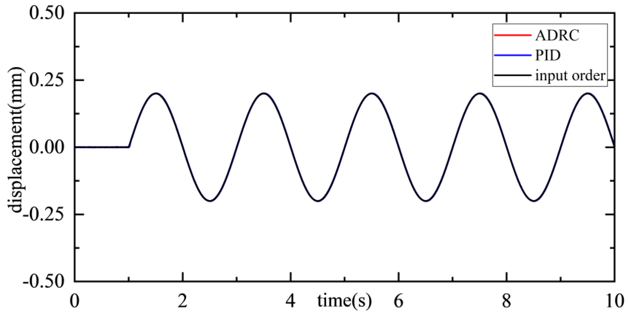
A simulation was conducted to evaluate the platform’s ability to track a small-amplitude, low-frequency sinusoidal command in the translational channel. As shown in Figure 24, the command 0.2 sin π t was applied at t = 1 s. Results indicate that both control strategies achieved effective command tracking.
As shown in Figure 24, the ADRCler demonstrates superior tracking performance, with its response curve closely following the input command variations, indicating better real-time behavior and accuracy. Specifically, the maximum deviation under ADRC is approximately 0.02 mm, outperforming the 0.03 mm observed under PID control, which reflects higher control precision and disturbance rejection capability. In terms of amplitude retention, ADRC also exhibits a clear advantage. For a 0.5 Hz sinusoidal reference signal, the amplitude attenuation with ADRC is less than 2.3%, compared to approximately 5.1% with PID control, further underscoring the stability and consistency of ADRC in dynamic response processes.
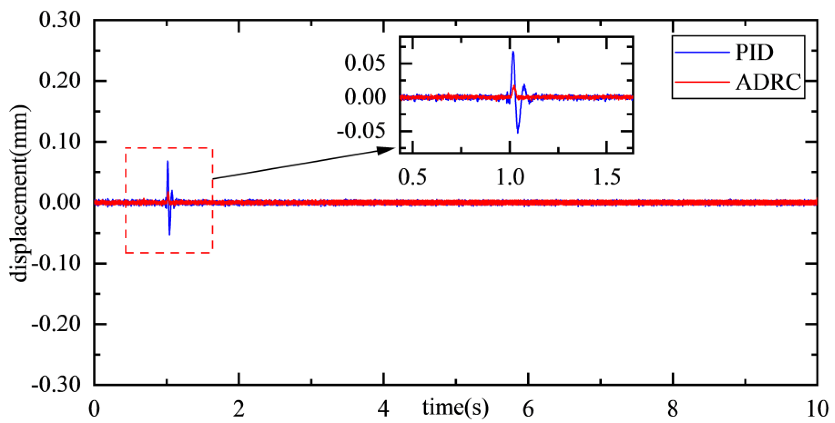
To evaluate the system’s disturbance rejection capability, a 0.1 mm instantaneous pulse signal was applied at t = 1 s during its stable equilibrium state, as illustrated in Figure 25.
As shown in Figure 25, the system demonstrates good stability during the initial steady-state phase, with fluctuations confined within ±0.01 mm, indicating high steady-state control performance of both controllers. When an external disturbance is applied at t = 1 s, the ADRC strategy exhibits strong anti-interference capability: the maximum fluctuation amplitude is only 0.017 mm, and the system rapidly returns to the equilibrium position within 0.06 s, demonstrating excellent dynamic adjustment characteristics. In contrast, under the same disturbance condition, the PID strategy shows inferior performance, with a peak fluctuation of 0.068 mm and a recovery time of 0.16 s to reattain stability. The simulation results clearly indicate that ADRC provides superior control performance in rejecting external disturbances, particularly in suppressing displacement deviations and improving recovery speed. Specifically, ADRC effectively reduces the transient displacement amplitude induced by disturbances and significantly shortens the settling time to reestablish steady-state operation.
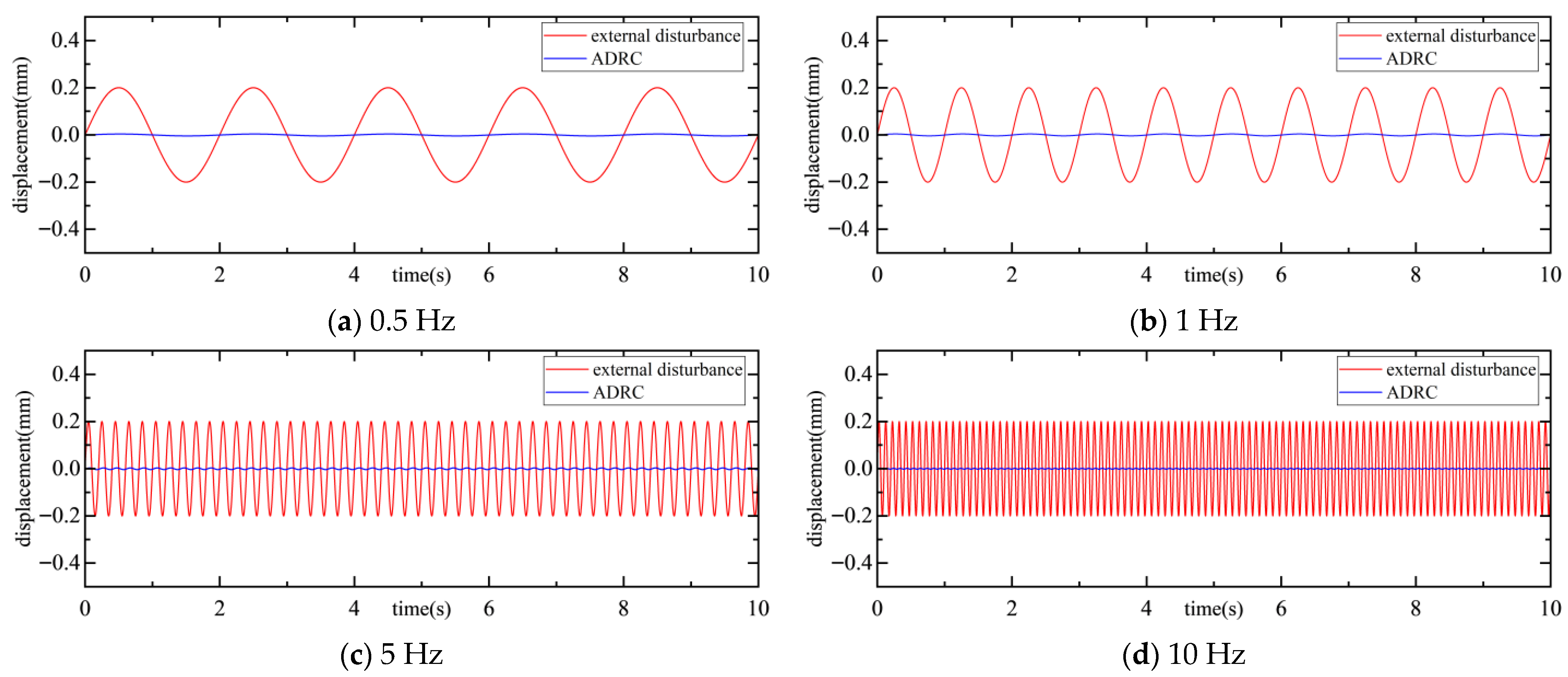
The platform was excited by low-frequency disturbances along the X-axis with an amplitude of 0.3 mm at frequencies of 0.5 Hz, 1 Hz, 5 Hz, and 10 Hz. The resulting displacement and acceleration response curves of the platform were recorded.
As shown in Figure 26 and Figure 27, under disturbance frequencies of 0.5 Hz, 1 Hz, 5 Hz, and 10 Hz, the maximum displacements of the platform are 0.004 mm, 0.004 mm, 0.0035 mm, and 0.0025 mm, respectively, corresponding to displacement attenuation rates of 98.02%, 98.02%, 98.24%, and 98.75%. The maximum acceleration deviations are 0.676 mm/s2, 1.352 m/s2, 6.772 m/s2, and 15.2 m/s2, with acceleration attenuation rates of 65.75%, 82.88%, 96.57%, and 98.07%, respectively. The corresponding vibration transmissibility values are summarized in Table 7.

5. Conclusions

In this study, the structural design and coupling characteristics of a Lorentz force magnetic levitation vibration isolation platform are investigated. Through theoretical modeling, numerical simulation, and coupled vibration isolation analysis, the following conclusions are drawn:
(1) The magnetic levitation vibration isolation platform employs a series configuration, which significantly reduces system complexity and eliminates the need for complex decoupling control typically required in parallel structures. The core actuation components—the planar actuator and the rotating magnetic bearing—are designed with standard cylindrical and annular permanent magnets, thus avoiding the need for custom magnetic parts. The rotating magnetic bearing utilizes a symmetric dual-magnetic-circuit layout with segmented fan-shaped magnets, while the planar actuator incorporates a multi-layer stacked PCB coil, a mature and low-cost technology, achieving a magnetic field uniformity exceeding 99%.
(2) An equivalent magnetic circuit model and an equivalent current model are established to describe the magnetic field in the working air gap of the planar Lorentz force actuator. These models allow preliminary determination of the magnetization length and its influencing factors, as well as the spatial distribution of the magnetic field. Finite element simulations validate the theoretical calculations, showing strong agreement with a maximum error of less than 4.1%. This confirms the rationality of the symmetric magnetic circuit design and demonstrates the effectiveness of both the symmetric yoke construction and the magnetic shielding layer.
(3) Utilizing the Active Disturbance Rejection Control (ADRC) algorithm, the extended state observer (ESO) estimates and compensates for the “total disturbance” in real-time, including residual coupling, model uncertainties, and external vibrations. Compared to traditional PID control, the ADRC strategy demonstrates superior disturbance rejection performance: for pulse disturbances of 0.1–0.5 mm, the maximum displacement deviation is reduced by 76.5–79.7%, and the recovery time is shortened by 42.1–71.4%. Furthermore, the vibration transmissibility of the platform remains below –35 dB across the 0.5–10 Hz frequency band, achieving performance comparable to that of classical magnetic levitation vibration isolation platforms.
(4) The current study has been primarily focused on simulation-based validation, with comprehensive hardware testing not yet fully conducted. The next phase of this research will involve systematic experimental investigations using the constructed hardware platform. These will include: (1) vibration isolation performance tests under typical disturbances of varying frequencies and amplitudes (e.g., from reaction wheels or cryocoolers), and (2) long-duration operational tests to evaluate the system’s stability and reliability.

Author Contributions

Conceptualization, B.L. and W.W.; formal analysis, C.Y. and Y.Y.; resources, Y.Y.; data curation, C.Y.; writing—original draft preparation, B.L.; writing—review and editing, W.W. and L.W.; visualization, C.Y.; project administration, W.W.; funding acquisition, W.W. All authors have read and agreed to the published version of the manuscript.

Funding

This research was supported in part by the National Natural Science Foundation of China under Grant 52075545.

Data Availability Statement

Data is contained within the article. The data that support the findings of this study are available from the corresponding author, upon reasonable request.

Conflicts of Interest

The authors declare no conflicts of interest.

References

  1. Zhou, X.B.; Ying, M.X.; Liu, X.T. Review on the Effect and Control Method of Micro-vibration for High-resolution Satellite. Shanghai Aerosp. 2024, 41, 140–147. [Google Scholar] [CrossRef]
  2. Gao, X.S.; Wang, G.Y.; Guan, S.; Yang, W.T.; Zhang, G.B.; Fan, L.J.; Zhao, Y.; Luo, W.B. Micro-vibration Attenuation Design and Verification for GFDM-1 Satellite. Spacecr. Eng. 2021, 30, 76–85. [Google Scholar] [CrossRef]
  3. Jiao, X.; Zhang, J.; Li, W.; Wang, Y.; Ma, W.; Zhao, Y. Advances in spacecraft micro-vibration suppression methods. Prog. Aerosp. Sci. 2023, 138, 100898. [Google Scholar] [CrossRef]
  4. Xing, W.; Tuo, W.; Li, X.; Wang, T.; Yang, C. Micro-vibration suppression and compensation techniques for in-orbit satellite: A review. Chin. J. Aeronaut. 2024, 37, 1–19. [Google Scholar] [CrossRef]
  5. Du, Y.G.; Wang, X.S.; Wang, Y.L. Research on an all-metal six-degree-of-freedom vibration isolation platform. J. Mech. Eng. 2023, 59, 188–198. [Google Scholar] [CrossRef]
  6. Geng, Z.J.; Pan, G.G.; Haynes, L.S.; Wada, B.K.; Garba, J.A. An intelligent control system for multiple degree-of-freedom vibration isolation. J. Intell. Mater. Syst. Struct. 1995, 6, 787–800. [Google Scholar] [CrossRef]
  7. Thayer, D.; Campbell, M.; Vagners, J.; Von Flotow, A. Six-axis vibration isolation system using soft actuators and multiple sensors. J. Spacecr. Rockets 2002, 39, 206–212. [Google Scholar] [CrossRef]
  8. Chen, H.-J.; Bishop, R.; Agrawal, B. Payload Pointing and Active Vibration Isolation Using Hexapod Platforms. In Proceedings of the American Institute of Aeronautics and Astronautics/American Society of Mechanical Engineers/American Society of Civil Engineers/American Helicopter Society Structures, Structural Dynamics, and Materials Conference, Norfolk, VA, USA, 7–10 April 2003. [Google Scholar] [CrossRef]
  9. Zhang, T.Q. Design and Experimental Study on Micro-Vibration Isolation of Whole Satellite Based on Stewart Platform Configuration Mechanism. Ph.D. Thesis, University of Chinese Academy of Sciences, Changchun, China, 2024. [Google Scholar]
  10. Nawratil, G. A remarkable set of Schönflies-singular planar Stewart Gough platforms. Comput. Aided Geom. Des. 2010, 27, 503–513. [Google Scholar] [CrossRef]
  11. Wang, J.M.; Kong, Y.F.; Huang, H. Cooperative control for vibration isolation and suppression based on Stewart platform. Vib. Shock 2019, 38, 186–194. [Google Scholar] [CrossRef]
  12. Hou, Y.; Zeng, D.; Yao, J.; Kang, K.; Lu, L.; Zhao, Y. Optimal design of a hyperstatic Stewart platform-based force/torque sensor with genetic algorithms. Mechatronics 2009, 19, 199–204. [Google Scholar] [CrossRef]
  13. Yan, J.; He, X.J.; Tang, L. Control method of electromagnetic suspension vibration isolation system. Electro-Opt. Eng. 1999, 26, 18–22. [Google Scholar]
  14. Carlos, M.G.; Stephen, W.M. Survey of active vibration isolation systems for microgravity applications. J. Spacecr. Rocket. 2000, 37, 586–596. [Google Scholar] [CrossRef]
  15. Edberg, D.L.; Harduvel, J.T.; Schenck, D.J. Non-Contacting Isolated Stabilized Microgravity Platform System. U.S. Patent US5638303, 10 June 1997. [Google Scholar]
  16. Whorton, M. Robust control for microgravity vibration isolation system. Spacecr. Rocket. 2005, 42, 152–160. [Google Scholar] [CrossRef]
  17. Hampton, R.; Calhoun, P.; Whorton, M. Glovebox Integrated Microgravity Isolation Technology: A Linearized State-Space Model. In Proceedings of the 42nd AIAA Aerospace Sciences Meeting and Exhibit, Reno, NV, USA, 5–8 January 2004. [Google Scholar] [CrossRef]
  18. Calhoun, P.; Hampton, D. Frequency Weighted H2 Control Design for the Glovebox Integrated Microgravity Isolation Technology. In Proceedings of the American Institute of Aeronautics and Astronautics Guidance, Navigation, and Control Conference and Exhibit, Austin, TX, USA, 11–14 August 2003. [Google Scholar]
  19. Zhang, W.; Zhao, Y.B.; Liao, H.; Zhao, H.B. Design of an Active-Quiet Isolated and Master-Slave Coordination Controlled Dual-Super Satellite Platform. Shanghai Aerosp. 2014, 31, 7–11+30. [Google Scholar] [CrossRef]
  20. Zhang, W.; Cheng, W.; You, W.; Chen, X.; Zhang, J.; Li, C.; Fang, C. Levitated-body ultra-high pointing accuracy and stability satellite platform of the CHASE mission. Sci. China Phys. Mech. Astron. 2022, 65, 289604. [Google Scholar] [CrossRef]
  21. Wu, Q.Q.; Cui, N.; Liu, B.L.; Yue, H.H.; Liu, R.Q. Dynamic model and control strategy of multi-dimensional magnetic levitation vibration isolation system. Acta Aeronaut. Astronaut. Sin. 2019, 40, 153–163. [Google Scholar] [CrossRef]
  22. Wu, Q.Q.; Yue, H.H.; Liu, R.Q.; Ding, L.; Deng, Z.Q. Parametric design and multiobjective optimization of maglev actuators for active vibration isolation system. Adv. Mech. Eng. 2014, 6, 215358. [Google Scholar] [CrossRef]
  23. Li, Q.; He, K.D.; Yang, H.J.; Xue, Y.J.; Ma, C.; Wang, T.S.; Liu, L. A study on a low-frequency active vibration isolation platform based on quasi-zero stiffness supporting structures. Vib. Shock 2024, 43, 84–91+117. [Google Scholar] [CrossRef]
  24. Pang, W.K.; Wang, W.J.; Fan, Y.H.; Li, L.; Yang, Y.; Zhu, H.Y. Design and analysis of double magnetic circuit rotating Lorentz force magnetic bearing. Beijing Univ. Aeronaut. Astronaut. 2024, 1–17. [Google Scholar] [CrossRef]
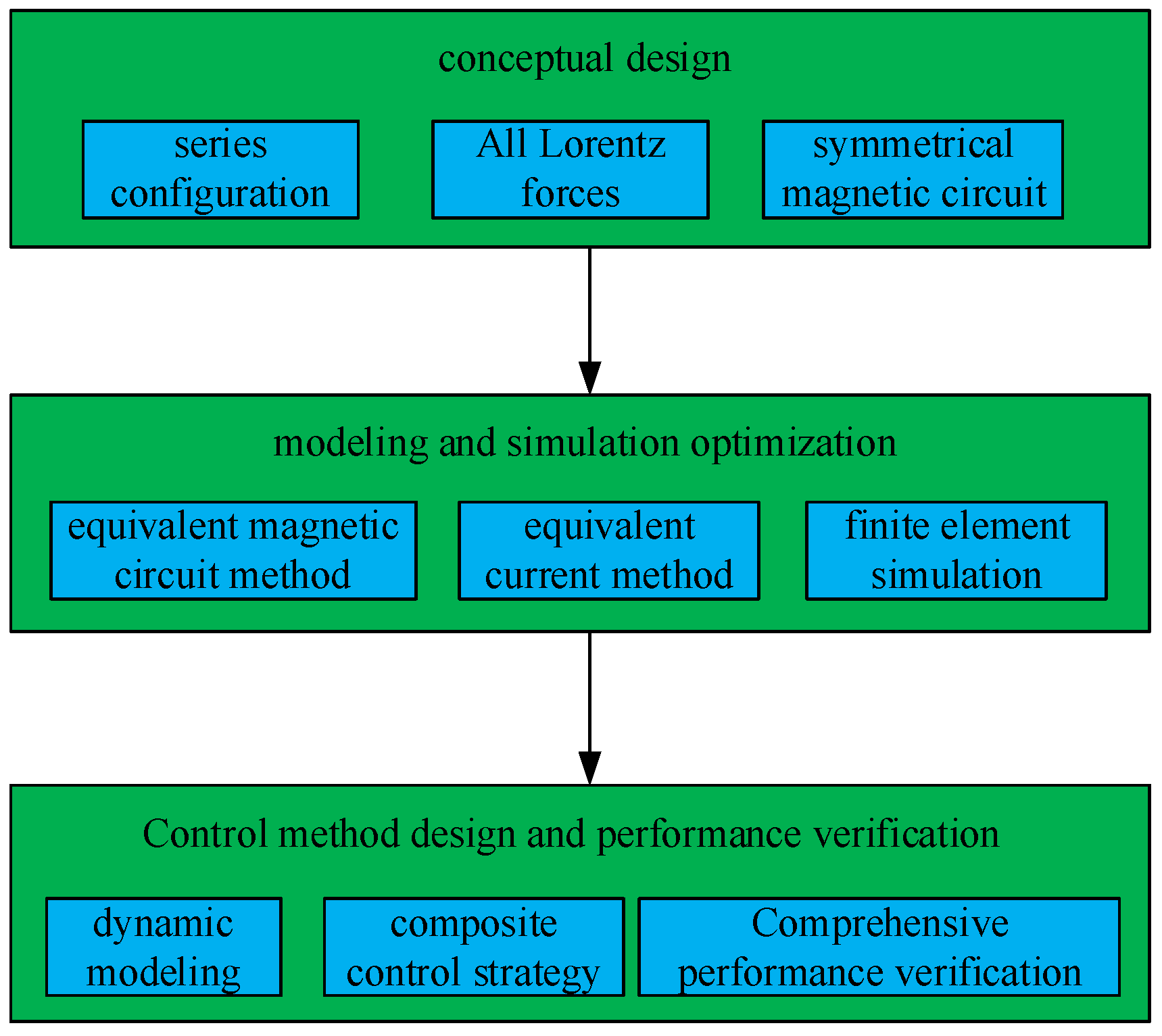
Figure 1. Overall research workflow.
Aerospace 12 00965 g001
Figure 2. Schematic of the Maglev Vibration Isolation Platform.
Aerospace 12 00965 g002
Figure 3. Schematic and Photo of the Rotating Magnetic Bearing Assembly.
Aerospace 12 00965 g003
Figure 4. Actuator Schematic and Assembly Photograph.
Aerospace 12 00965 g004
Figure 5. Magnetic Flux Path in the Actuator.
Aerospace 12 00965 g005
Figure 6. Actuator Schematic and Photograph.
Aerospace 12 00965 g006
Figure 7. Equivalent parallel magnetic circuit diagram of actuator.
Aerospace 12 00965 g007
Figure 8. Equivalent series magnetic circuit diagram of actuator.
Aerospace 12 00965 g008
Figure 9. Schematic of the Actuator Structure.
Aerospace 12 00965 g009
Figure 10. Variation in Magnetic Flux Density with Magnetization Length.
Aerospace 12 00965 g010
Figure 11. Spatial Magnetic Field Distribution.
Aerospace 12 00965 g011
Figure 12. Magnetic Field Distribution of the Actuator.
Aerospace 12 00965 g012
Figure 13. Three-dimensional Finite Element Model.
Aerospace 12 00965 g013
Figure 14. Schematic of the Magnetic Field Distribution.
Aerospace 12 00965 g014
Figure 15. Comparison of air gap magnetic induction intensity.
Aerospace 12 00965 g015
Figure 16. Axial Flux Density vs. Magnetization Length.
Aerospace 12 00965 g016
Figure 17. Circumferential Distribution of Magnetic Flux Density in the Air Gap.
Aerospace 12 00965 g017
Figure 18. Schematic of the Platform Coordinate System.
Aerospace 12 00965 g018
Figure 19. The offset of Z axis.
Aerospace 12 00965 g019
Figure 20. Distribution of air gap magnetic field intensity.
Aerospace 12 00965 g020
Figure 21. Diagram of disturbing force.
Aerospace 12 00965 g021
Figure 22. Diagram of single degree of freedom output Lorentz force.
Aerospace 12 00965 g022
Figure 23. Schematic of the Controller Structure.
Aerospace 12 00965 g023
Figure 24. X-axis sine tracking curve.
Aerospace 12 00965 g024
Figure 25. Transient Response to X-Axis Disturbance.
Aerospace 12 00965 g025
Figure 26. Displacement Response: Controlled vs. Uncontrolled.
Aerospace 12 00965 g026
Figure 27. Acceleration Response: Controlled vs. Uncontrolled.
Aerospace 12 00965 g027
Table 1. Comparison of typical vibration isolation platforms.
NamePrincipleIsolation Frequency Bandwidth
(Hz)
Vibration Transmissibility
(dB)
HAVIsix-bar parallel mechanism/active or passive control10–250−15
HT/UWsix-bar parallel mechanism/active or passive control10–80−20
UQPsix-bar parallel mechanism/active or passive control5–400−40 (50–200 Hz)
STABLE/G-LIMITMagnetic levitation/active control0.01–100−34
Table 2. Key parameters of the vibration isolation platform.
ParameterValue
body dimension376 mm × 310 mm × 193 mm
total mass35.73 kg
isolation frequency bandwidth0.5 Hz–100 Hz
Table 3. Properties of common permanent magnet materials.
MaterialRemanent Magnetism
Br (T)
Coercive Force
Hc (kA/m)
Magnetic Energy Product (BH)max
(MGOe)
T max (°C)
NdFeB1.0–1.4800–200035–55200
SmCo0.8–1.15600–150020–32350
Ferrite0.2–0.4150–3003–5250
AlNiCo0.6–1.350–1505–10550
Table 4. Properties of common magnetic materials.
MaterialSaturation Induction
Bs (T)
Coercive Force
Hc (A/m)
Permeability μ i × 10 3 T max (°C)
30Q1302.010–201.5–1.8750
DT4C2.1570–1003–5770
1J222.4120–1603–4940
1J501.64–810–20500
1J790.851–250–100460
1J850.780.2–150–150455
Table 5. Specifications of the rotating magnetic bearing.
ParameterValue
outer diameter of permanent magnet ring R p m , o u t 57 mm
inner diameter of permanent magnet ring R p m , i n 35 mm
circumferential of permanent magnet ring θ p m 140 mm
thickness of permanent magnet ring t p m 8 mm
outer diameter of magnetic guide ring R c o r e , o u t 77 mm
inner diameter of magnetic guide ring R c o r e , i n 35 mm
circumferential of magnetic guide ring θ c o r e 160°
outer diameter of magnetic isolation ring R i s o , o u t 69 mm
inner diameter of magnetic isolation ring R i s o , i n 57 mm
air gap radial distance g r 20 mm
air gap axial distance g a 6 mm
outer diameter of coil bracket R b , o u t 67 mm
inner diameter of coil bracket R b , i n 18 mm
thickness of coil bracket t b 5 mm
outer diameter of coil outer ring R c , o u t o u t 65 mm
inner diameter of coil outer ring R c , i n o u t 57 mm
outer diameter of coil inner ring R c , o u t i n 34 mm
inner diameter of coil inner ring R c , i n i n 24 mm
Table 6. Specifications of actuator.
ParameterValue
radius of permanent magnet
R m
36.5 mm
thickness of permanent magnet
H m
7 mm
thickness of air gap
L g
15 mm
length of carrier board
L c
214 mm
thickness of carrier board
δ c
1 mm
length of isolation layer
L b
214 mm
thickness of isolation layer
H b
1 mm
thickness of yoke plate
H y
7 mm
thickness of shielding layer
H s
5 mm
Table 7. Vibration transmissibility by frequency.
Frequency (Hz)Transmissibility (dB)
0.5−34.07
1−34.06
5−35.11
10−38.05
Disclaimer/Publisher’s Note: The statements, opinions and data contained in all publications are solely those of the individual author(s) and contributor(s) and not of MDPI and/or the editor(s). MDPI and/or the editor(s) disclaim responsibility for any injury to people or property resulting from any ideas, methods, instructions or products referred to in the content.