Article

Enhanced Ablation Resistance of Silicone Composites in Oxygen-Rich High-Temperature Environment for Solid Fuel Ramjet Applications

1
National Key Laboratory of Solid Rocket Propulsion, School of Astronautics, Northwestern Polytechnical University, Xi’an 710072, China
2
Inner Mongolia Power Machinery Institute, Hohhot 010010, China
3
School of Power and Energy, Northwestern Polytechnical University, Xi’an 710072, China
*
Author to whom correspondence should be addressed.
Aerospace 2025, 12(11), 961; https://doi.org/10.3390/aerospace12110961 (registering DOI)
Submission received: 17 September 2025 / Revised: 15 October 2025 / Accepted: 24 October 2025 / Published: 28 October 2025
(This article belongs to the Section Astronautics & Space Science)

Abstract

The ablation resistance of silicone-based thermal protection materials in high-temperature, oxygen-rich environments remains insufficiently understood, yet it is critical for the design of thermal management systems in Solid Fuel Ramjets (SFRJs). To address this challenge, we first performed a three-dimensional two-phase flow simulation of an SFRJ combustion chamber under typical flight conditions, obtaining key parameters including temperature, pressure, and oxygen concentration. Based on these thermal boundaries, we developed an advanced ablation simulation device capable of replicating the coupled high-enthalpy oxidative and erosive environment within the chamber. Using this platform, we systematically evaluated silicone rubber composites reinforced with functional fillers and fibers. Results demonstrate that incorporating ZrB2 significantly enhances thermal stability and promotes the formation of an antioxidative ceramic layer. Furthermore, hybrid composites containing both organic and inorganic fibers exhibit superior erosion resistance due to the formation of a dense and stable char layer with a reinforced skeletal structure. This work not only provides an efficient experimental methodology for screening thermal insulation materials but also offers fundamental insights for the design of advanced ablation-resistant composites tailored to SFRJ applications.

1. Introduction

The development of Solid Fuel Ramjets (SFRJs) has been persistently constrained by the challenge of ensuring long-term thermal protection under extreme operational conditions [1,2]. Within the SFRJ combustion chamber, materials are exposed to severe high-temperature oxidative ablation and high-velocity particle erosion, which collectively exceed the endurance limits of conventional thermal protection systems [3,4].
Two principal thermal protection strategies are currently employed in SFRJ ramjet chambers: active and passive systems. Among these, passive protection, achieved through the application of ablative materials to chamber walls, has gained widespread adoption due to its operational simplicity and effectiveness in reducing heat flux and preserving structural integrity.
Silicone rubber has attracted significant interest as a base material for thermal protection owing to its notable heat resistance, chemical stability, and low thermal conductivity. Ongoing research continues to explore its potential, leading to the development of silicone rubber-based composites reinforced with inorganic fillers, fibers, and flame retardants, which are now commonly used in SFRJ applications [5,6].
However, the distinctive operational environment of ramjet chambers, particularly its high oxygen concentration and erosive particle flow, precludes direct extrapolation of material performance from solid rocket motors. Previous attempts to simulate oxygen-rich environments have involved methods such as oxygen supplementation in solid propellant chambers [7] or the introduction of alumina particles into oxygen/kerosene rocket exhausts [8,9]. Wang et al. [10] further adapted these approaches by injecting particles directly into the combustion chamber to better emulate erosive conditions. While these methods replicate certain aspects of the ablation environment, they involve hazardous materials, entail lengthy preparation, incur high costs, and are thus unsuitable for preliminary screening of silicone-based insulation materials.
Research on the ablation behavior of silicone rubber has primarily focused on mechanistic studies and modeling efforts. For instance, methyl vinyl silicone rubber, a key material in this study, undergoes thermal decomposition primarily into cyclic siloxanes, leaving minimal carbonized residue [11,12,13]. The ionic character of the Si–O bond facilitates rearrangement reactions upon heating, yielding volatile cyclic compounds with good thermal stability [14,15]. Thermal oxidation initiates with the formation of side-chain peroxides, followed by oxidative cleavage of substituents, producing gaseous products such as CO2 and H2O, and solid residues dominated by SiO2 [16]. Existing ablation models include charring ablation and liquid-layer ablation models. The former describes a four-layer structure under steady ablation, though shear-induced recession of the liquid layer may occur [17,18]; the latter differentiates itself by the explicit presence of a liquid layer on the char surface.
Given these complexities, it is imperative to investigate the ablation mechanisms of insulating materials under conditions specific to SFRJ operation. Understanding how material composition influences ablation behavior will not only reveal fundamental mechanisms but also facilitate the establishment of performance criteria, thereby accelerating the development of tailored thermal protection strategies [19,20,21].
In this study, we address these challenges through a combined numerical and experimental approach. We first simulate the three-dimensional two-phase flow within an SFRJ chamber to accurately characterize the thermal boundaries. Based on these results, we develop an improved ablation testing apparatus capable of replicating the coupled oxidative and erosive environment. Using this platform, we systematically evaluate silicone rubber composites enhanced with functional fillers and fibers, focusing on their ablation resistance and erosion behavior. This work provides both a practical methodology for material screening and new insights into the design of high-performance ablation-resistant composites for SFRJ applications.

2. Numerical Characterization of Typical SFRJ Chamber Flow Field

Accurate characterization of the thermal environment is a prerequisite for designing effective thermal protection systems. Given the challenges of obtaining detailed in situ measurements within an operating SFRJ chamber, computational fluid dynamics (CFD) serves as an indispensable tool [22,23]. This section aims to characterize the flow field of the target SFRJ configuration in detail, establishing precise thermal boundary conditions for the subsequent design of the ablation device and material testing.

2.1. Governing Equations and Numerical Models

The simulation solved the three-dimensional, steady-state Reynolds-Averaged Navier–Stokes (RANS) equations to describe the reacting two-phase flow within the chamber. To account for density variations in the high-speed compressible flow, the conservation equations for mass, momentum, energy, and species transport were solved in their Favre-averaged form.
Turbulence modeling: The shear stress transport (SST) k-ω model was employed due to its well-recognized accuracy in simulating diffusion-controlled combustion processes— a defining feature of ramjet chambers [22,23]. This two-equation eddy-viscosity model integrates the strengths of the k-ω model (high precision in the near-wall region) and the k-ε model (reliability in the far-field), enabling accurate predictions of flows involving adverse pressure gradients and flow separation.
Gas-phase combustion model: The finite-rate/eddy-dissipation model was used to simulate the secondary combustion of fuel-rich gaseous products with incoming air. Reaction rates were determined by the smaller value between the rate derived from Arrhenius kinetics and the turbulent mixing rate. A global single-step reaction mechanism was applied to the CO-H2-air system [24].
Discrete phase model (DPM): The particle phase was tracked using a Lagrangian framework. Particle trajectories were computed by integrating the force balance acting on each particle, including drag, gravitational, and thermophoretic forces. The stochastic tracking (random walk) model was employed to account for the influence of turbulent eddies on particle dispersion.
Heterogeneous reactions: The combustion of boron and carbon particles was modeled through surface reactions. The diffusion-limited rate model was applied, in which the reaction rate is governed by the diffusion of oxidizer toward the particle surface [24].
The particle size distribution followed a Rosin-Rammler distribution, with a mean diameter of 70 μm and a spread parameter of 3.5—consistent with the characteristics of typical propellant combustion products [3].

2.2. Computational Setup and Mesh Independence

The flow field inside the ramjet chamber was simulated under realistic SFRJ operating conditions: an altitude of 20 km, a flight Mach number of 3.5, and an overall air-fuel ratio of 15. Taking advantage of the SFRJ’s axisymmetric geometry, only half of the chamber was modeled to reduce computational cost.
Mesh independence study: Three systematically refined grids were assessed to verify the grid independence of the solutions.
  • Coarse mesh: 1.1 million hexahedral cells;
  • Medium mesh: 2.22 million hexahedral cells (adopted in this study);
  • Fine mesh: 3.8 million hexahedral cells.
Key parameters monitored to confirm convergence included wall heat flux, pressure distribution, and species concentrations at characteristic locations. The differences in these parameters between the medium and fine grids were less than 2% [25], confirming that the medium grid (2.22 million hexahedral elements) offered sufficient resolution while preserving computational efficiency.
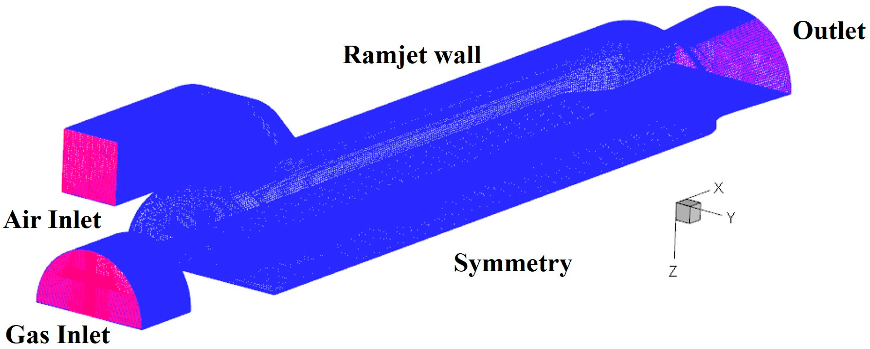
As illustrated in Figure 1, the computational mesh consists entirely of hexahedral elements—ensuring high-quality numerical discretization and accurate capture of boundary layer phenomena.
The computational model includes a gas inlet, an air inlet, a ramjet wall, a symmetry plane, and a pressure outlet. The air inlet was defined using a mass flow rate and total temperature derived from the flight conditions and inlet geometry (see Table 1). The incoming gas comprised 35% gaseous phase and 65% particulate phase by mass. Gaseous species that did not participate in secondary combustion were modeled as N2, with detailed mass fractions provided in Table 2. The chamber wall was treated as a no-slip, adiabatic boundary [26].
The mass fractions in Table 2 were derived from a stoichiometric analysis of a typical boron-based fuel-rich propellant composition, with mass balance verified to ensure conservation. The gaseous phase represents the combustion products of primary combustion, while the particulate phase consists of unburned boron and carbon residues, as well as boron oxide products formed during combustion.

2.3. Model Validation

To establish confidence in the numerical approach, the simulation methodology was validated against experimental data from a subscale ramjet combustor test reported in our previous work [25]. In the validation case, the measured wall pressure distribution was reproduced with a maximum deviation of 8%, and the overall combustion efficiency was predicted to be within 5% of the experimental value. This level of agreement confirms the credibility of the modeling approach for the current SFRJ configuration.

2.4. Flow Field Results and Analysis

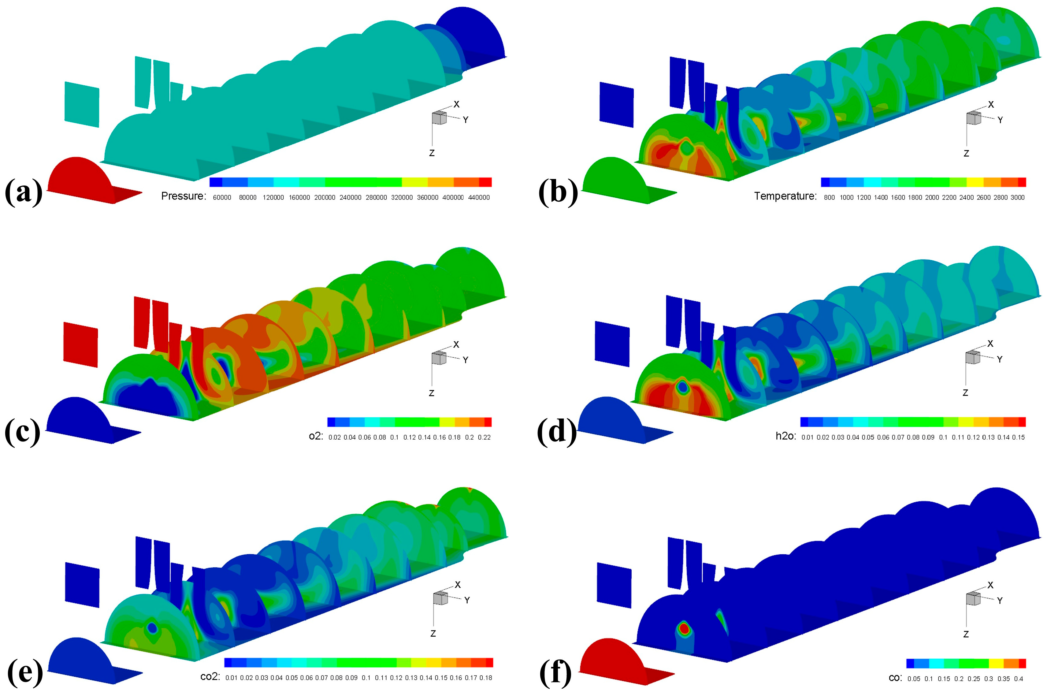
Figure 2 presents the spatial distributions of key flow field properties near the chamber wall, which were obtained under the applied boundary conditions and numerical models.
The results reveal significant spatial inhomogeneity in thermo-fluid properties, allowing the chamber to be divided into four distinct zones:
(i)
A high temperature mixing and combustion region adjacent to the air inlet.
(ii)
An oxygen-enriched zone with O2 mass fractions ranging from 16% to 23%. This localized oxygen enrichment—exceeding the ambient volume fraction of ~21%—is a key characteristic of the fuel-rich SFRJ cycle and stems from three combined effects: First, the high-speed air inlet supplies a continuous flow of fresh oxidizer. Second, the primary combustion products from the gas generator are fuel-rich (as shown in Table 2) and only consume a portion of the available oxygen during mixing and secondary combustion. Third, the heterogeneous combustion of boron and carbon particles is diffusion-limited and does not instantaneously consume all surrounding oxygen, resulting in localized pockets of high oxygen concentration in the near-wall region—especially in areas where mixing remains incomplete.
(iii)
A transition region characterized by increasing temperature and decreasing concentrations of oxidizing species.
(iv)
A particle combustion zone near the aft section of the chamber, where incoming particulates from primary combustion undergo further oxidation—elevating local wall temperatures.
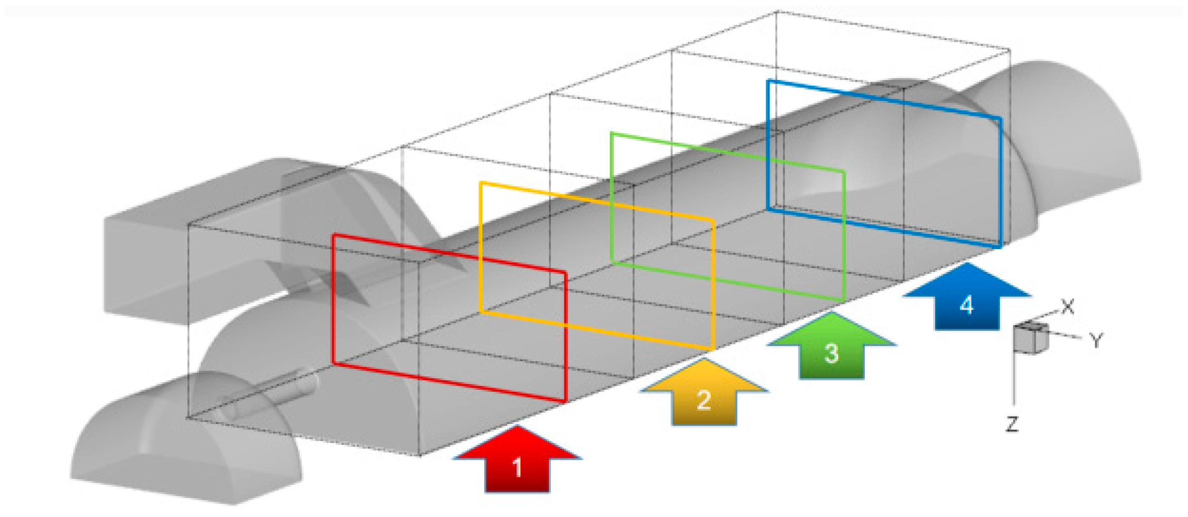
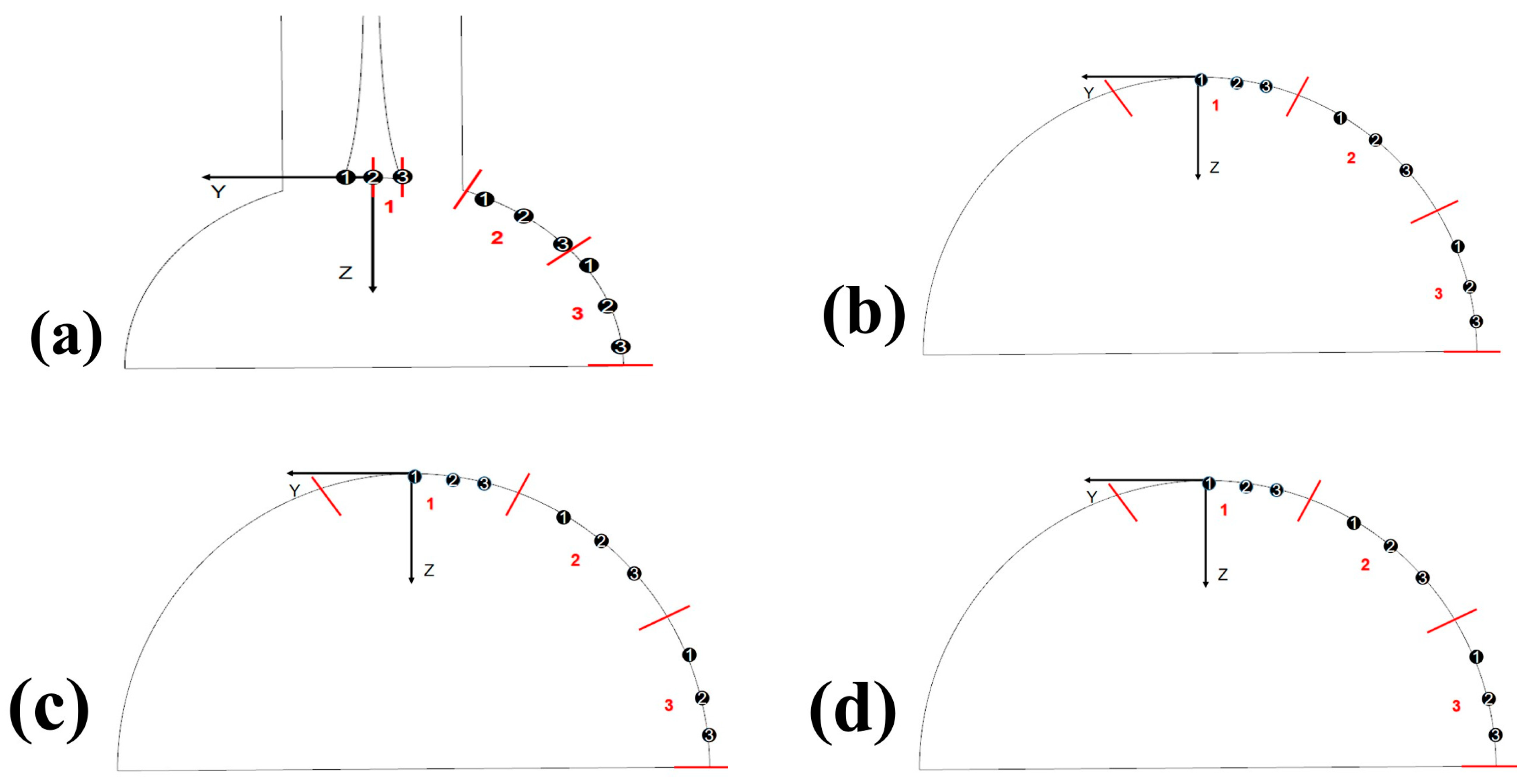
To enable a detailed analysis of local ablation mechanisms, the chamber was divided into four regions as depicted in Figure 3. For each region, a representative surface was selected and subdivided into three linear segments (Figure 4). Three sampling points were placed along each segment, and average values were calculated to represent the local conditions.
The average gas parameters for each region are summarized in Table 3, Table 4, Table 5 and Table 6. These results confirm the initial flow field analysis: from Region 1 to Region 4, the gas temperature first decreases and then increases, while the O2 mass fraction rises from nearly zero to a maximum of 23% before declining to 13.9%. These parameter profiles provide representative near-wall environmental conditions—critical for evaluating thermal protection materials in typical SFRJ chambers.

3. Design of an Ablation Device for Simulating Thermal Environment Within the Ramjet Chamber

The ablation resistance of insulation materials is a critical factor determining the overall performance and reliability of solid fuel ramjets (SFRJs). During SFRJ operation, the inner wall of the combustion chamber is exposed to extreme conditions: high-temperature, oxygen-rich gas flows, and mechanical erosion from particles (e.g., Al, Mg, B) and other combustion residues. These combined thermo-chemical and mechanical loads impose severe demands on the thermal protection system.

3.1. Current Devices and Their Associated Problems

Current understanding of how insulation materials—particularly silicone rubber—behave under such multi-factor coupled conditions remains limited. As a result, ground ignition tests of SFRJs frequently fail due to inadequate thermal protection. While empirical attempts have been made to modify materials by adjusting their composition, establishing a scientifically rigorous design and prediction methodology remains challenging. This gap primarily stems from two key issues: insufficient insight into ablation mechanisms, and a lack of reliable testing approaches tailored to high-oxygen, erosive environments. Consequently, insulation materials currently used in ramjet chambers often rely on existing formulations (rather than being systematically optimized for high-oxygen conditions), and their performance must ultimately be validated through costly, time-consuming full-scale ground firing tests.
Plasma wind tunnels are state-of-the-art facilities capable of simulating high-enthalpy aerodynamic heating environments—such as those encountered by spacecraft at altitudes of 20–75 km and Mach numbers of 3–20. These systems offer advantages including high enthalpy, high heat flux, and extended operational durations. As illustrated in Figure 5, a typical plasma wind tunnel operates by introducing protective gases (e.g., nitrogen or argon) into the arc plasma cathode and a trigger electrode. The plasma torch is ignited using a working gas between the trigger and transition electrodes, which sustains an arc between the cathode and anode. By precisely regulating the flow rates of protective/working gases and the arc current, stable plasma jets can be generated across a range of power levels [27,28,29].
However, conventional plasma wind tunnels exhibit two major limitations when used to simulate the internal environment of an SFRJ combustion chamber:
(i)
It typically operates under low-pressure or near-vacuum conditions, which do not replicate the high-pressure environment inside a ramjet chamber.
(ii)
It lacks the capability to introduce erosive particles, failing to simulate particle-induced ablation—a key contributor to material degradation in SFRJs.

3.2. Design and Validation of the Ablation Simulation Devices

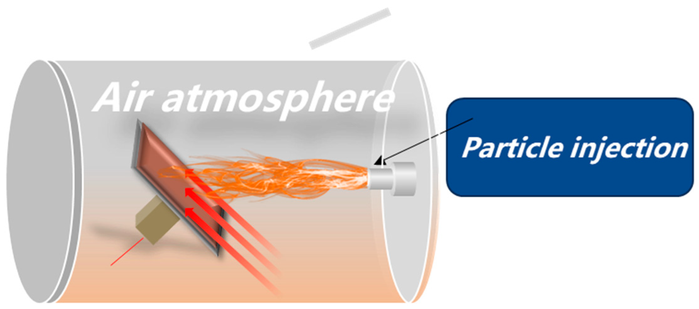
To address these limitations, an enhanced ablation simulation device was developed based on existing plasma wind tunnel technology. Key modifications included two critical upgrades: the integration of a particle injection system, and the removal of the vacuum chamber (enabling operation under atmospheric pressure). A schematic of the redesigned device is presented in Figure 6.
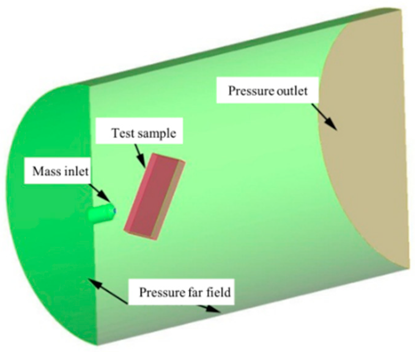
To validate the device’s ability to replicate SFRJ chamber conditions, a three-dimensional two-phase flow numerical simulation was conducted using the methods and boundary conditions outlined in Section 2. The computational domain—illustrated in Figure 7—includes a mass flow inlet, a pressure far-field boundary, a test sample wall, and a pressure outlet. The nozzle outlet axis was positioned 50 mm from the test sample, with the sample inclined at 60° relative to the axis. This inclination angle was chosen to more accurately simulate the actual flow impingement conditions in an SFRJ chamber (where flow is rarely normal to the wall). Oblique impingement creates combined normal and shear stresses, which better represent the erosive environment experienced by insulation materials in practical SFRJ operation.
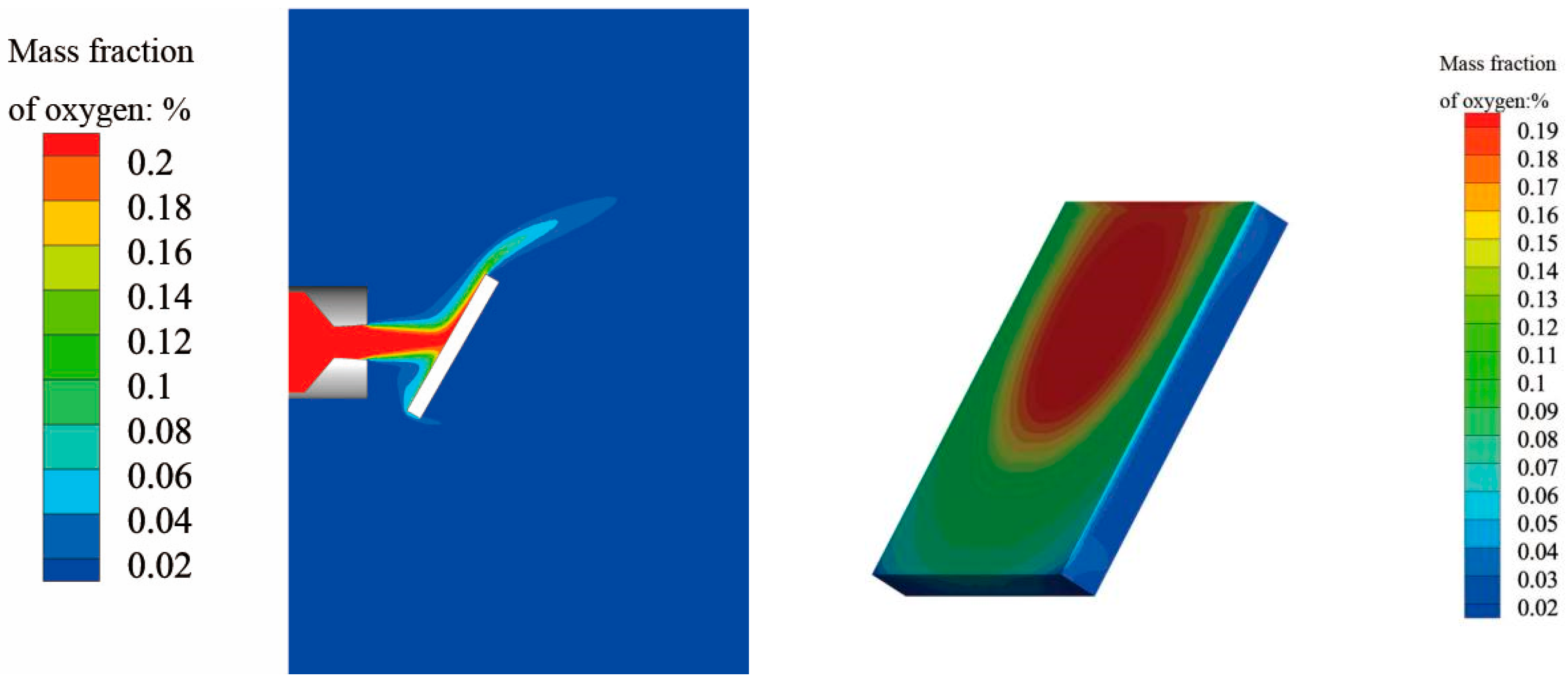
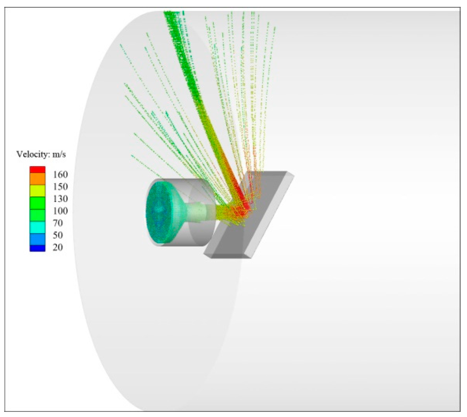
Figure 8, Figure 9 and Figure 10 present the simulated distributions of temperature, O2 mass fraction, and pressure within the domain, respectively. The results show that the average temperature on the sample surface reaches 2000 K, with an O2 mass fraction of 17% and a pressure of 130 kPa—values that align closely with the conditions identified in Region 4 of the SFRJ chamber (Table 6). Furthermore, Figure 11 illustrates particle trajectories (color-coded by velocity), confirming the device’s ability to simulate particle erosion at controllably high speeds. Collectively, these numerical results confirm that the proposed device effectively replicates the thermal and chemical conditions inside an SFRJ combustion chamber, providing a viable platform for studying insulation material ablation under simultaneous oxygen enrichment and particle erosion.
To further validate the numerical simulations, surface heat flux measurements were conducted using calibrated water-cooled calorimeters; the results showed good agreement with predicted values (within 15%). Additionally, oxygen partial pressure was verified using zirconia-based sensors, confirming the accuracy of the simulated O2 mass fraction distribution.
Key improvements over conventional plasma wind tunnels include the following:
  • Modifications to the arc generator environment and nozzle structure to achieve the target flow parameters (e.g., temperature, pressure) matching SFRJ conditions.
  • Integration of a dedicated particle injection channel to simulate particle erosion.
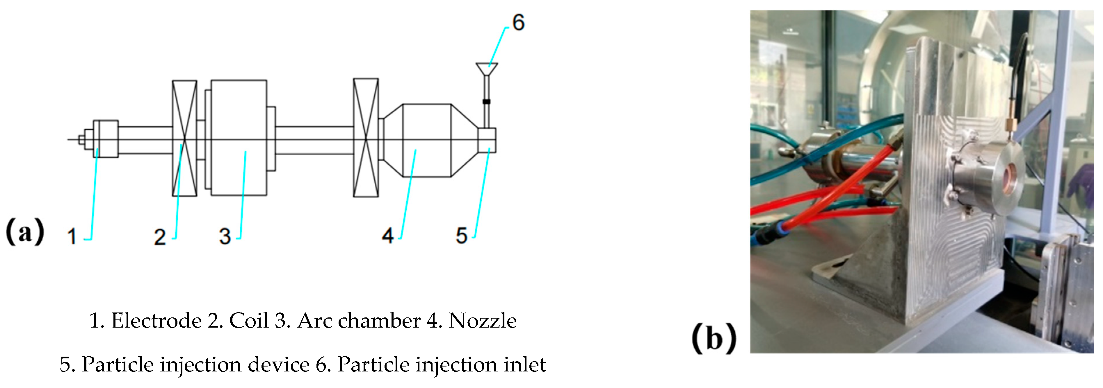
The enhanced device consists of water-cooled copper electrodes (front and rear), arc chambers, magnetic coils, a contoured nozzle, and a particle injection inlet. During operation, a high-voltage current ionizes the air between the electrodes, generating a high-intensity arc discharge. This arc heats purified air (with adjustable oxygen content) injected into the arc chamber at high pressure, producing a high-temperature test flow. The device can deliver a main flow rate of 0.8 kg/s, achieve test pressures up to 1 MPa, and generate flow temperatures exceeding 2500 K. A schematic and photograph of the actual setup are provided in Figure 12.
To accurately simulate the erosive environment of SFRJ chambers, particles with high thermal resistance, low density, good flowability, and near-spherical morphology were selected. Alumina (Al2O3) particles were chosen due to their similarity to real propellant combustion products; these particles are fed uniformly through the particle injection unit. The particle flow rate is precisely controlled via a pressure differential system and throttling valves.
The experimental system allows independent adjustment of four critical parameters, enabling customization to match specific SFRJ operating conditions:
  • Oxygen enrichment: Controlled by varying the air/oxygen ratio in the working gas, with an adjustable range of 0–45%.
  • Surface temperature: Regulated by adjusting the gas flow rate and arc current, operable from 1200 to 3000 K, with real-time monitoring via infrared thermometry.
  • Ablation pressure: Adjusted by modifying the distance between the sample and the nozzle, capable of reaching 0.8 MPa.
  • Particle erosion velocity: Controlled by the nozzle throat diameter and gas flow rate, with a maximum velocity of 350 m/s. This maximum velocity was selected based on literature data for alumina particles in SFRJ combustion chambers [30], ensuring representative erosion conditions for material screening.
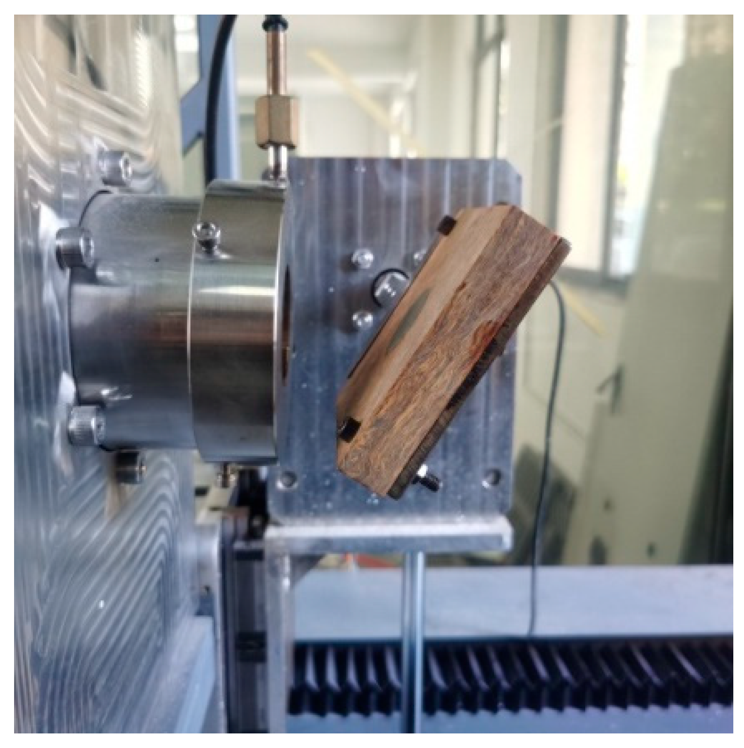
Figure 13 shows a photograph of the actual ablation simulation device.

4. Impact of Formulations on the Ablation Resistance of Silicone-Based Materials

Silicone-based thermal protection materials generally comprise a silicone matrix reinforced with functional fillers and ablation-resistant fibers. Given the relatively low intrinsic strength of silicone rubber, incorporating fillers is essential for enhancing its mechanical properties [31]. Furthermore, adding fibers can facilitate the formation of a network structure within the material, which strengthens the char layer and improves its adhesion to the underlying matrix. This study systematically investigates how different types of fillers and fibers influence the ablation resistance of silicone rubber composites.
The fabricated composites were characterized using field emission scanning electron microscopy (FESEM). Their thermal stability was evaluated via thermogravimetric analysis (TGA) conducted in air, with the temperature ramped from room temperature to 1000 °C at a heating rate of 5 K/min—simulating the atmospheric environment inside an SFRJ combustion chamber. Although the TGA heating rate (5 K/min) is much lower than the rapid heating rates (>1000 K/s) encountered in actual SFRJ operation, this controlled approach provides valuable comparative data on the relative thermal stability and decomposition mechanisms of different composite formulations under oxidative conditions.
The ablation device described earlier was used to replicate the thermal conditions of the SFRJ chamber. K-type thermocouples were attached to the back of each sample to record temperature profiles during testing.

4.1. Role of Functional Fillers

As previously noted, the SFRJ combustion chamber operates under high-temperature, oxygen-rich conditions. Previous studies have demonstrated that incorporating inorganic fillers (e.g., zirconium-containing compounds or silicon carbide) into silicone matrices facilitates the formation of solid or liquid antioxidant films on the material surface [17]. This protective layer acts as a barrier, reducing direct contact between oxidizing gases and the pristine matrix to mitigate ablation.
Silicon carbide (SiC) promotes the formation of a liquid SiO2 film under high-temperature oxidative conditions. In comparison, zirconium diboride (ZrB2) reacts to form liquid B2O3 and a solid ZrO2 skeleton. However, at temperatures exceeding 2073 K, B2O3 evaporates faster than it can form; in contrast, SiO2 exhibits viscous flow at around 2000 K, enabling the formation of a continuous protective layer while retaining its ceramic properties and protective function up to 3000 K [32].
Thus, combining SiC and ZrB2 can provide effective ablation resistance across a broad temperature range. Additionally, silica (SiO2) fillers contribute to mechanical reinforcement. This section examines the synergistic effects of SiC, ZrB2, and SiO2 fillers.
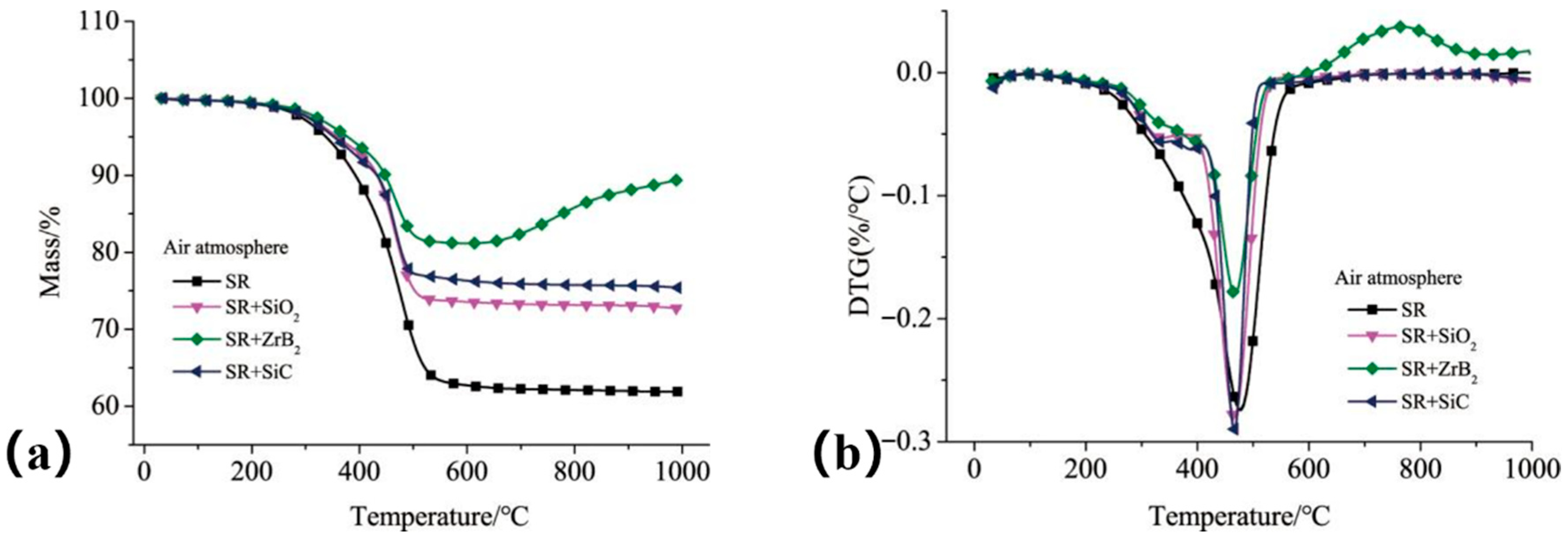
In this study, 50 phr (parts per hundred rubber) of SiC, ZrB2, or SiO2 was individually incorporated into a silicone rubber (SR) matrix to evaluate their effects on thermal stability. Figure 14 shows the TGA and derivative thermogravimetric (DTG) curves. The composite containing ZrB2 exhibited the lowest mass loss, with a residual mass of 89.4% at 1000 °C. In contrast, the composite with SiO2 filler showed the highest mass loss. This is because, at the 5 K/min heating rate, the inert SiO2 filler primarily dilutes the polymer matrix without actively contributing to the formation of a protective ceramic residue (as ZrB2 does) or promoting stable char formation (as SiC can). Consequently, the overall residual mass fraction is lower. However, it is critical to emphasize that this TGA result does not capture the potential beneficial role of SiO2 under dynamic ablation conditions: at higher temperatures (>1800 °C), SiO2 melts and flows viscously, which can significantly contribute to forming a continuous, erosion-resistant protective layer—an effect demonstrated in subsequent ablation tests (see Figure 16 and the discussion of Formulation S3). The mass increase observed above 780 °C (Figure 14b) is attributed to the oxidation of ZrB2, which produces a porous ZrO2 framework and a liquid B2O3 layer that collectively inhibit oxidative degradation of the matrix.
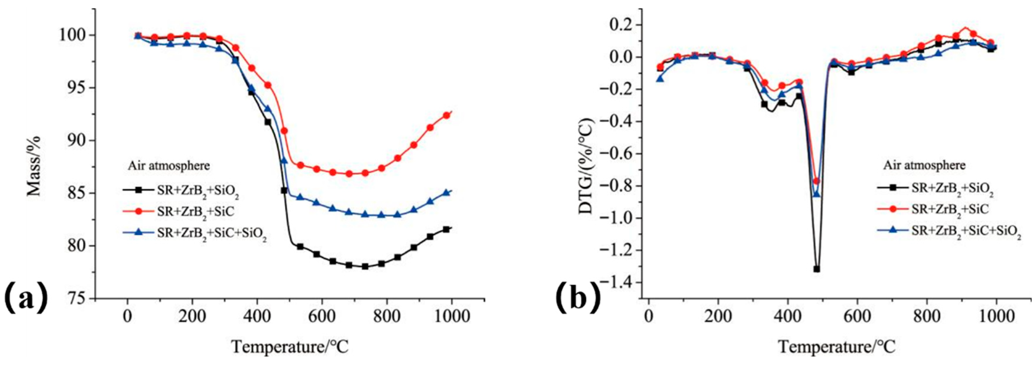
To further explore the thermal stability and ablation behavior of composites containing ZrB2 with different filler combinations, additional experiments were conducted. In each composite formulation, the content of ZrB2 and SiC was maintained at 50 phr, while SiO2 was fixed at 30 phr—a proportion previously found to optimize the balance between mechanical properties and ablation resistance. The specific compositions of these composites are listed in Table 7.
As shown in Figure 15, Composite S1—formulated with only ZrB2 and SiO2—exhibited the highest residual mass (92.69%, Figure 15a) and the lowest maximum mass loss rate among the three composites (Figure 15b). However, results from dynamic simulated ablation tests (Figure 16) revealed that Composite S3 (incorporating SiC, ZrB2, and SiO2) had the lowest mass ablation rate.
The SiO2 filler provides mechanical reinforcement, and its melting behavior at high temperatures contributes to forming a continuous liquid antioxidant layer. This layer effectively resists two-phase flow erosion and works in tandem with the ceramic fillers to establish a stable antioxidative film during ablation. Consequently, Composite S3 exhibits superior dynamic ablation resistance compared to the other formulations.

4.2. Influence of Fibers

All fiber-reinforced composites (S4, S5, S6) were tested under standardized ablation conditions to ensure comparable results. The test parameters were set as follows: surface temperature maintained at 2000 ± 50 K (controlled via infrared pyrometer feedback); O2 mass fraction of 17 ± 1% in the test stream; chamber pressure of 130 ± 5 kPa; alumina particle (mean diameter: 70 μm) mass flow rate of 2.0 ± 0.1 g/s; and test duration fixed at 180 s. These conditions were selected to replicate the severe environment identified in Region 4 of the SFRJ chamber simulation (Table 6).
To further enhance the composites’ erosion resistance, fibrous reinforcements were incorporated into the S3 baseline formulation. Two types of short fibers—aramid fibers (AF) and carbon fibers (CF)—were added to investigate their effects on the composites’ thermal stability and erosion resistance. The specific formulations are summarized in Table 8.
These fibrous reinforcements are expected to improve both the mechanical properties and oxidation resistance of the silicone rubber matrix—critical for withstanding gas–solid two-phase flow conditions in the SFRJ chamber. Aramid fibers possess a ternary copolymer aromatic heterocyclic amide structure, whereas carbon fibers are composed of carbonaceous material. Both fiber types act as a skeletal framework within the matrix, enhancing the composite’s erosion resistance.
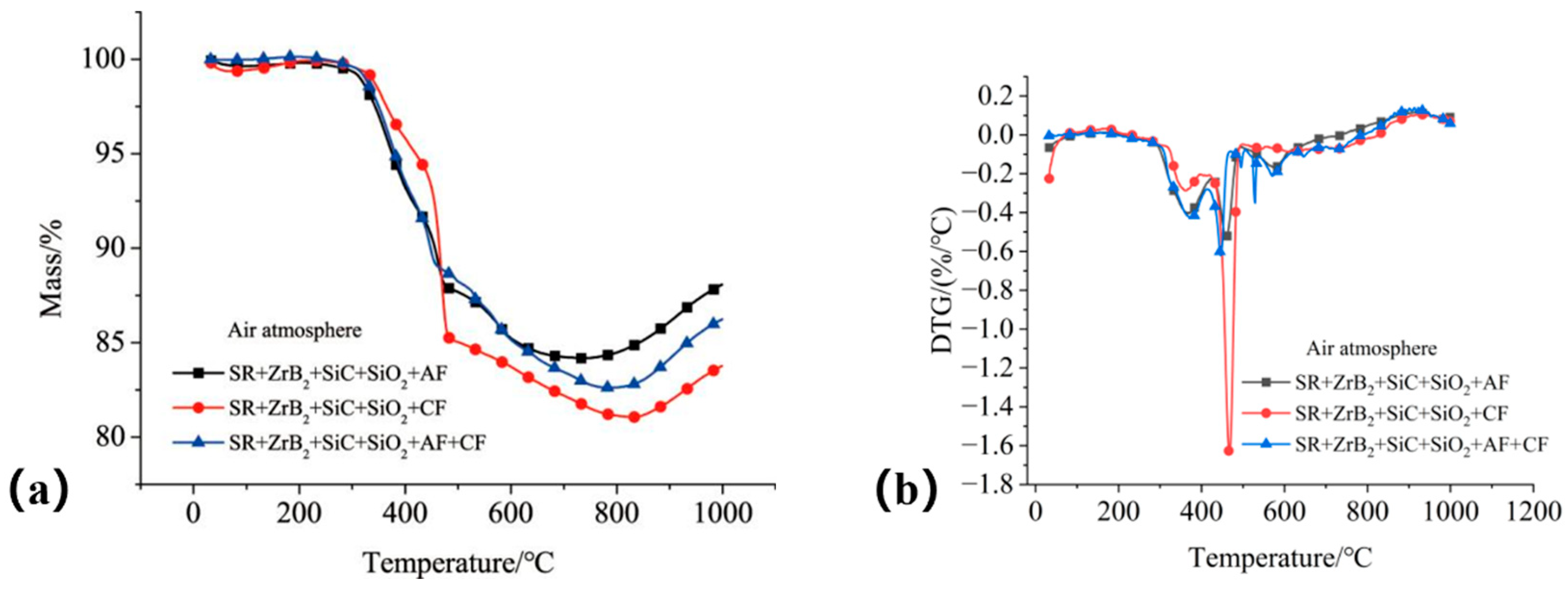
The thermal stability of the fiber-reinforced composites was evaluated via TGA and DTG analyses, as shown in Figure 17. Composites incorporating aramid fibers (S4 and S6) exhibited the lowest mass loss, with residual masses of 87.6% and 85.2% at 1000 °C, respectively, indicating that aramid fibers improve thermal stability. All fiber-reinforced composites displayed a distinct DTG peak in the range of 430–450 °C, suggesting a significant degradation process occurs within this temperature interval.
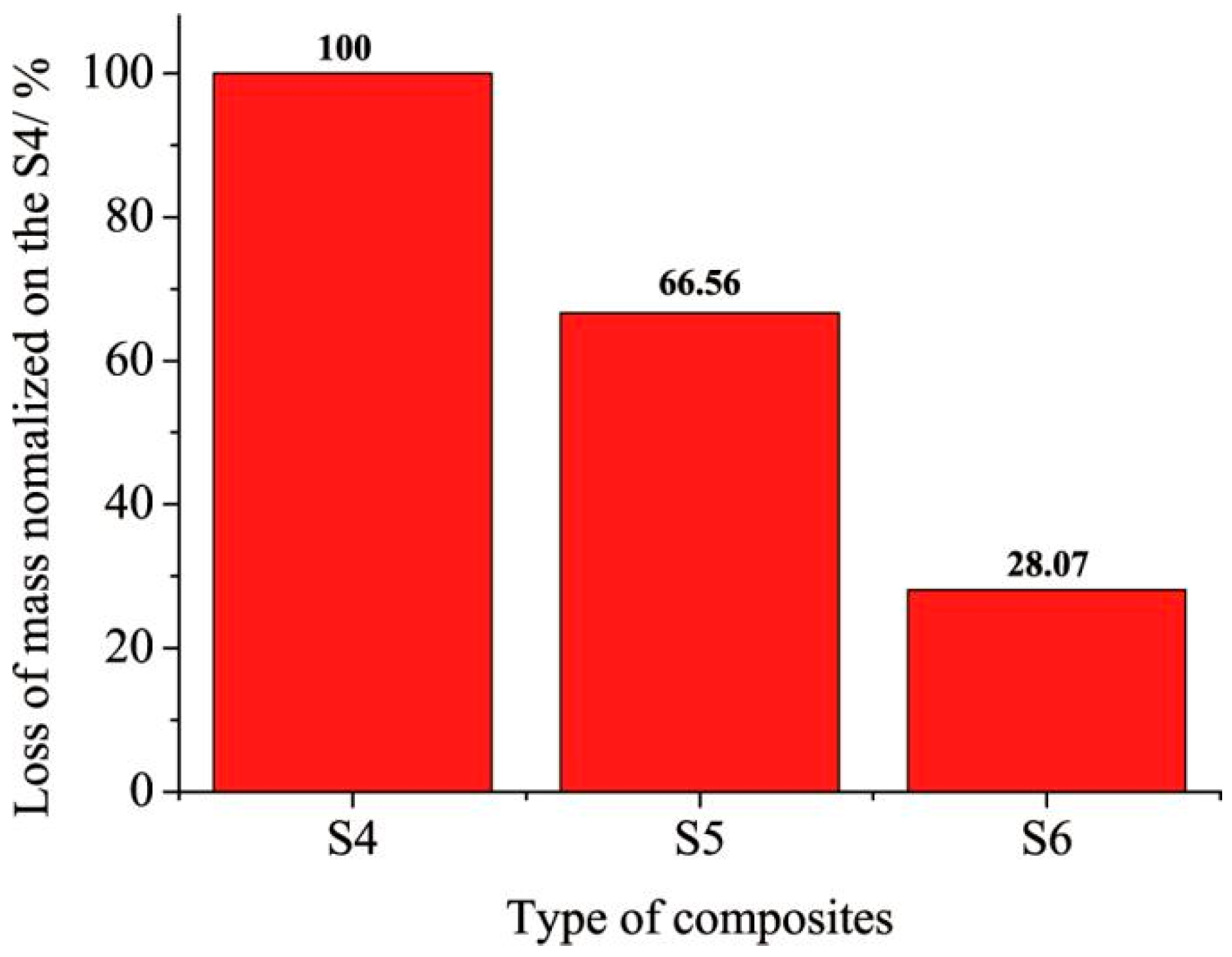
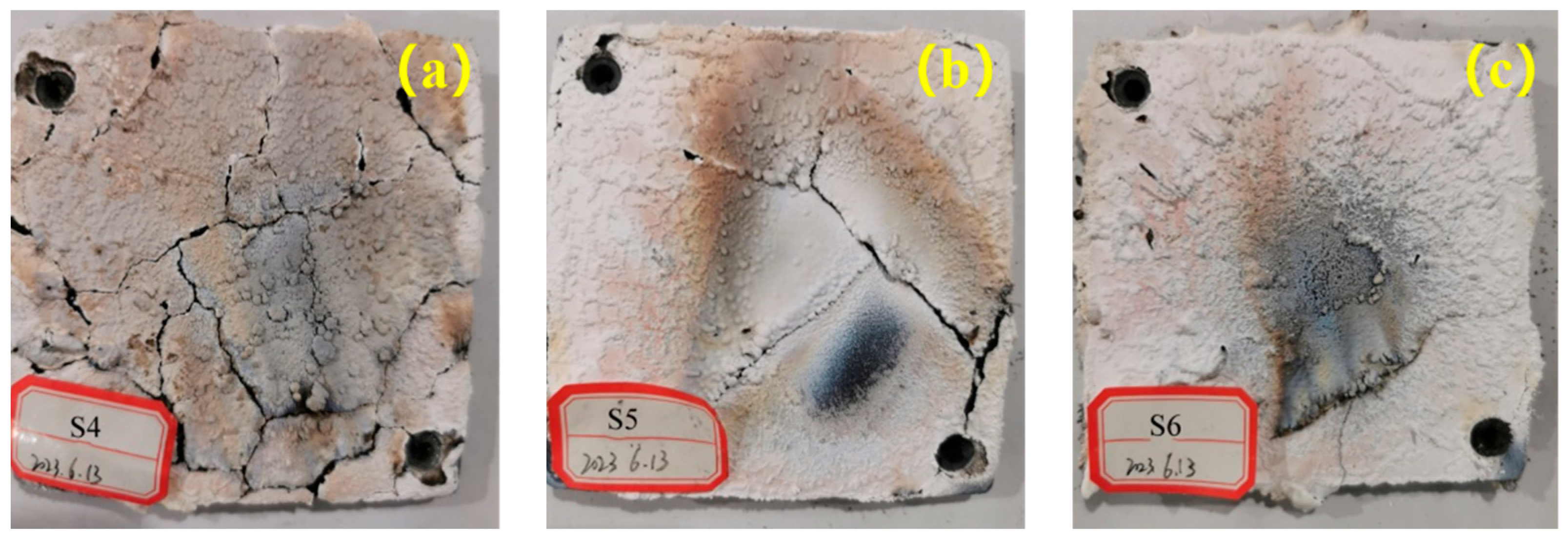
However, under simulated ablation conditions (180 s duration), composites reinforced with carbon fibers (S5) showed superior erosion and oxidation resistance, with the lowest normalized mass loss (Figure 18). Although the hybrid fiber composite (S6) visually exhibited a more compact char structure (Figure 20c), its mass loss was slightly higher than that of S5. This can be attributed to the oxidative decomposition of the aramid fiber component in S6 under the high-temperature, oxygen-rich environment—an effect schematized in Figure 19. In contrast, the carbon fibers in S5 are fully carbonized and inorganic, giving them superior intrinsic thermo-oxidative stability compared to organic aramid fibers. This explains why S5 retained more mass under these severe conditions. The contrast between thermal stability (from TGA) and ablation performance highlights that different fibers enhance distinct aspects of the composite’s behavior: aramid fibers improve thermal stability, while carbon fibers boost ablation resistance under erosive and oxidative conditions.
In high-temperature, oxygen-rich environments, aramid fibers undergo oxidative decomposition, as illustrated in Figure 19. According to the literature [33], aramid fibers undergo thermal degradation at approximately 500 °C in air, releasing gases such as CO2, H2O, CO, HCN, and NO2. Weak aromatic heterocyclic bonds break within this temperature range; between 600 °C and 700 °C, complex depolymerization and restructuring reactions lead to nearly complete decomposition. In contrast, carbon fibers—being fully carbonized inorganic materials—react with oxidizing gases only under more extreme temperature conditions.
Figure 20 shows post-ablation images of the charred surfaces of Composites S4, S5, and S6. Visually, the composite reinforced with carbon fibers (S5) had a compact, flat char surface with no macrocracks—unlike S4. The hybrid fiber composite S6 (Figure 20c) also displayed a highly coherent, defect-free surface that appeared structurally superior to S5. This excellent structural integrity of S6 is likely due to a synergistic effect: aramid fibers pyrolyze and expand to fill voids, while carbon fibers provide a stable skeletal framework. However, as evidenced by the mass loss data (Figure 18), this superior macroscopic structure does not directly translate to optimal ablation resistance under the specific thermo-chemical stress of the oxygen-rich environment—where the chemical stability of the carbon fibers in S5 dominates. TGA results indicated that composites containing carbon fibers (S5 and S6) produced a higher char yield, contributing to the formation of a stronger char skeleton.
SEM analysis (Figure 21) showed that S4 had numerous voids and cracks in its char layer—indicative of a weak skeletal structure caused by pyrolysis and gas release from aramid fibers. In contrast, S5 exhibited a denser, more continuous char structure, attributed to the supporting role of carbon fibers. S6—incorporating both fiber types—also showed a compact char structure: inorganic carbon fibers acted as a skeleton, while pyrolytic products from aramid fibers filled voids, further improving ablation resistance.
These microstructural observations align with the macroscopic images: S6 possesses a very compact, integrated char layer. However, the critical difference lies in the chemical nature of the reinforcing skeleton. In S5, the carbon fiber skeleton remains largely intact, providing continuous mechanical reinforcement against erosion. In S6, while the initial structure is excellent, the decomposition of aramid fibers can lead to localized weakening upon prolonged exposure, making it slightly more susceptible to mass loss under combined thermo-chemical and mechanical attack. This explains why S5, with its chemically inert fibrous skeleton, achieved the lowest ablation rate.
In summary, incorporating either carbon fibers (S5) or a hybrid of organic and inorganic fibers (S6) significantly improved the compactness and mechanical integrity of the char layer, leading to markedly enhanced ablation resistance.
5. Conclusions

This study addresses the critical challenge of developing ablative thermal protection for silicone-based materials in the extreme environment of solid fuel ramjet (SFRJ) chambers—characterized by high temperatures, oxygen enrichment, and particle erosion. A comprehensive investigation integrating numerical simulation, experimental device development, and material testing was conducted, yielding the following key findings:
  • Thermal environment characterization of the SFRJ chamber was achieved via three-dimensional two-phase flow simulations under typical flight conditions. These simulations successfully captured the harsh near-wall environment, identifying distinct regions with temperatures up to ~2100 K, oxygen mass fractions as high as ~23%, and significant pressure variations. The precise thermal boundary conditions derived from this analysis provided essential guidance for the subsequent design of ablation tests and material evaluation.
  • A novel ablation simulation device was developed by modifying a conventional plasma wind tunnel, addressing the limitations of existing equipment. Key enhancements included the integration of a particle injection system (to replicate particle erosion) and adjustments to enable operation at atmospheric pressure (to match the SFRJ chamber’s high-pressure environment). This device reliably reproduced the coupled thermo-chemical and erosive conditions of the SFRJ chamber (e.g., temperature > 2000 K, oxygen mass fraction > 17%, pressure ~130 kPa), establishing a cost-effective and accurate ground-testing platform for screening insulation materials.
  • Filler optimization revealed that functional fillers significantly enhance the ablation resistance of silicone-based composites. Zirconium diboride (ZrB2) was particularly effective: it improved thermal stability and promoted the formation of a protective ceramic residue through its oxidation products (ZrO2 and B2O3). A synergistic effect was observed in the S3 formulation (reinforced with SiC/ZrB2/SiO2), where SiO2 contributed dual benefits—mechanical reinforcement and the formation of a continuous liquid antioxidant layer during ablation. This combination resulted in the lowest dynamic ablation rate among all filler-based composites tested.
  • The mechanism of fiber reinforcement highlighted the critical role of fiber type in maintaining char layer integrity under ablation. Composites reinforced solely with organic aramid fibers (S4) suffered severe structural degradation due to fiber pyrolysis and gas evolution, leading to a porous, weak char layer. In contrast, composites incorporating inorganic carbon fibers (S5, S6) formed compact, coherent, and mechanically robust char layers with reinforced skeletal structures. This structural enhancement translated to significantly improved resistance to oxidation and particle erosion. Notably, while the hybrid fiber composite (S6, aramid + carbon fibers) exhibited exceptional char layer integrity (due to aramid fibers filling voids and carbon fibers providing a stable skeleton), its mass loss was slightly higher than that of S5—attributed to the oxidative decomposition of aramid fibers in the high-temperature, oxygen-rich environment.
In summary, this work establishes an integrated methodology—spanning numerical analysis, experimental simulation, material synthesis, and performance evaluation—for the development of advanced ablative materials. The optimal composite formulation, featuring a synergistic blend of ZrB2/SiC/SiO2 fillers and carbon fibers, demonstrates superior ablation resistance and thus offers a promising solution for thermal protection systems in SFRJ applications.
Finally, while the current study identifies the carbon fiber-reinforced composite (S5) as the most ablation-resistant based on mass loss metrics under simulated conditions, it also highlights that the hybrid fiber composite (S6) may exhibit superior performance in environments where mechanical erosion dominates over thermo-chemical oxidation. Future work will therefore focus on validating these formulations under full-scale engine testing conditions to further clarify their performance hierarchy and explore synergies between fiber types across a broader range of SFRJ operational scenarios.

Author Contributions

Conceptualization, Y.G. and X.Y.; methodology, Y.G.; software, Z.W.; validation, W.Z.; formal analysis, Y.B.; investigation, X.Y.; data curation, X.Y.; writing—original draft preparation, Y.G.; writing—review and editing, Y.G.; visualization, X.Y.; supervision, X.Y.; project administration, W.Z.; funding acquisition, W.Z. All authors have read and agreed to the published version of the manuscript.

Funding

This work was supported by the Solid Rocket Propulsion National Key Laboratory Foundation Project of China (Grant No. 2024010201); The Stable Support Project of Inner Mongolia Power Machinery Research Institute (46004520X-24JJSXXYYZ-0782); “One Case One Discussion Project” of Xi’an Science and Technology Program in 2024 (Grant No. 24GJSY0013-04).

Data Availability Statement

The original contributions presented in this study are included in the article. Further inquiries can be directed to the corresponding author.

Conflicts of Interest

The authors declare no conflicts of interest.

References

  1. Cheng, J.; Yan, H.; Feng, X.; Zhu, G.; Liu, J.; Qi, X. Research on Ablation Device Suitable for Thermal Protection System of Solid Rocket Ramjet. Aerospace 2025, 12, 772. [Google Scholar] [CrossRef]
  2. Li, L.; Chen, X.; Zhou, C.; Li, W.; Zhu, M. Experimental and model investigation on agglomeration of aluminized fuel-rich propellant in solid fuel ramjet. Combust. Flame 2020, 219, 437–448. [Google Scholar] [CrossRef]
  3. Liu, Y.; Guan, Y.; Li, J.; Liu, P.; Zhang, X. Insulator ablation modes in different impact conditions of alumina droplets onto wall surfaces. Acta Astronaut. 2018, 153, 138–145. [Google Scholar] [CrossRef]
  4. Liu, Y.; Li, X.-C.; Zhu, P.-F.; Xi, K. Ablation characteristics of insulator under high-temperature gas dual-pulse erosion. Def. Technol. 2022, 18, 1875–1885. [Google Scholar] [CrossRef]
  5. Hamdani, S.; Longuet, C.; Perrin, D.; Lopez-Cuesta, J.-M.; Ganachaud, F. Flame retardancy of silicone-based materials. Polym. Degrad. Stab. 2009, 94, 465–495. [Google Scholar] [CrossRef]
  6. Camino, G.; Lomakin, S.; Lageard, M. Thermal polydimethylsiloxane degradation. Part 2: The degradation mechanisms. Polymer 2002, 43, 2011–2015. [Google Scholar] [CrossRef]
  7. Lou, Y.C.; Yu, X.J.; He, G.Q.; Li, J.; Chen, J. A simulation experimental method for insulation ablation under oxygen-rich conditions. J. Solid Rocket. Technol. 2006, 29, 229–231. [Google Scholar]
  8. Koo, J.; Dave, W.; Ofoolike, A.E. A review of numerical and experimental characterization of thermal protection materials, Part I numerical modeling. In Proceedings of the 42nd AIAA/ASME/SAE/ASEE Joint Propulsion Conference Exhibit, Sacramento, CA, USA, 9–12 July 2006. [Google Scholar]
  9. Allcorn, E.K.; Natali, M.; Koo, J.H. Ablation performance and characterization of thermoplastic polyurethane elastomer nanocomposites. Compos. Part A Appl. Sci. Manuf. 2013, 45, 109–118. [Google Scholar] [CrossRef]
  10. Wang, J.J.; Zhang, B.L.; Zhang, W.; Zhang, Y. Experimental method research on ablation characteristics of thermal insulation material under multi-phase flow conditions. J. Astronaut. 2019, 40, 362–368. [Google Scholar]
  11. Jovanovic, J.D.; Govedarica, M.N.; Dvornic, P.R.; Popovic, I.G. The thermos gravimetric analysis of some polysiloxanes. Polym. Degrad. Stab. 1998, 61, 87–93. [Google Scholar] [CrossRef]
  12. Radhakrishnan, T.S. New method for evaluation of kinetic parameters and mechanism of degradation from pyrolysis-GC studies: Thermal degradation of polydimethylsiloxanes. J. Appl. Polym. Sci. 1999, 73, 441–450. [Google Scholar] [CrossRef]
  13. Hayashida, K.; Tsuge, S.; Ohtani, H. Flame retardant mechanism of polydimethylsiloxane material containing platinum compound studied by analytical pyrolysis techniques and alkaline hydrolysis gas chromatography. Polymer 2003, 44, 5611–5616. [Google Scholar] [CrossRef]
  14. Zhao, W.L.; Liu, Y.; Dong, Z.C.; Yu, X.J. Establishment of strain rate-dependent intrinsic models for short-cut carbon fiber/nitrile composites in different pyrolysis states. Polym. Compos. 2024, 45, 8321–8334. [Google Scholar] [CrossRef]
  15. Liu, Y.; Dong, Z.; Wang, H.; Zou, Y.; Gao, Y.; Wang, Z. Study on heat transfer model of solid rocket motor combustor under high-temperature two-phase flow scour state. Int. Commun. Heat Mass Transf. 2023, 145, 106845. [Google Scholar]
  16. Andrianov, K.A. Metalorganic Polymers; Interscience: New York, NY, USA, 1965. [Google Scholar]
  17. Afshar, M.; Walia, J.; Berini, P.; Variola, F.; Bhardwaj, R. Raman spectroscopic characterization of femtosecond laser ablation of silicon in air and liquid medium. Appl. Surf. Sci. 2025, 702, 163258. [Google Scholar] [CrossRef]
  18. Yan, Z.; Mei, X.; Wang, W.; Fan, Z.; Pan, A.; Zheng, Q. Theoretical investigation of multipulse femtosecond laser processing on silicon carbide: Ablation, shielding effect, and recast formation. Opt. Laser Technol. 2025, 181 Pt C, 111976. [Google Scholar] [CrossRef]
  19. Guo, M.; Zhang, P.; Yu, K.; Yang, J.; Wang, H.; Zhang, Y.; Du, J.; Zhu, D. Hollow microsphere-reinforced ablative materials for thermal protection systems of solid rocket motors. Acta Astronaut. 2024, 221, 309–317. [Google Scholar] [CrossRef]
  20. Meiirbekov, M.; Sadykov, M.; Kuandyk, A.; Nurzhanov, M.; Yesbolov, N.; Baiserikov, B.; Kulbekov, A. Modern thermal protection systems for solid rocket motors: A comparative review of composite manufacturing technologies. Results Eng. 2025, 27, 106550. [Google Scholar] [CrossRef]
  21. Khan, G.R.; Ud Din, L.M. Advanced thermal barrier nanocoating using gold-stabilized tetragonal zirconia on alumina for rocket propellant tank systems. Colloids Surf. A Physicochem. Eng. Asp. 2025, 726 Pt 1, 138028. [Google Scholar] [CrossRef]
  22. Zhang, R.; Liu, Y.; Zou, Y.; Peng, M.; Wang, Z.; Yu, X. Numerical Method for Chemical Non-Equilibrium Plume Radiation Characteristics of Solid Rocket Motors. Aerospace 2025, 12, 736. [Google Scholar] [CrossRef]
  23. Peng, M.; Zou, Y.; Zhang, R.; Ba, Y.; Liu, Y. A Study on the Influence of Flight Parameters on Two-Phase Flow and Radiation in the Plume of Solid Rocket Motors. Aerospace 2025, 12, 711. [Google Scholar] [CrossRef]
  24. Chang, Y.; Wu, Z.; Zhang, Z.; Cheng, J.; Wang, N.; Hou, X. Combustion characteristics of solid fuel ramjets with multi-ring diaphragms. Appl. Therm. Eng. 2025, 271, 126265. [Google Scholar] [CrossRef]
  25. Liu, Y.; Gao, Y.G.; Yu, X.J.; Huo, D.; Yang, Y. Preliminary experimental study on solid rocket fuel gas scramjet. Acta Astronaut. 2018, 153, 146–153. [Google Scholar] [CrossRef]
  26. Zhang, Y.; Sun, Z.; Hu, Y.; Zhu, Y.; Xia, X.; Qu, H.; Tian, B. Numerical Simulation of the Gas Flow of Combustion Products from Ignition in a Solid Rocket Motor Under Conditions of Propellant Creep. Aerospace 2025, 12, 153. [Google Scholar] [CrossRef]
  27. Scurtu, A.; Ticoș, D.; Diplașu, C.; Udrea, N.; Mitu, M.L.; Paraschiv, B.; Ticoș, C.M. Pulsed coaxial plasma jets for CO2 dissociation at Martian pressures: Magnetic confinement for modeling local supercritical conditions. Results Phys. 2025, 76, 108395. [Google Scholar] [CrossRef]
  28. Yang, J.; Liu, D.; Ge, X.; Tong, Q.; Li, X.; Liu, Y. Study on the mid infrared emission spectral characteristics of high enthalpy air plasma jet. Infrared Phys. Technol. 2025, 151, 106068. [Google Scholar] [CrossRef]
  29. Ramezani, M.B.; Ghasempour, H.; Jalar, N.R. Investigating of oxidative properties of a homemade multi-array plasma jet for prussian blue synthesis. Mater. Chem. Phys. 2025, 346, 131378. [Google Scholar] [CrossRef]
  30. Hu, B.; Li, J.; Xu, J.; Bai, H.; Wang, Y. Excellent ablation resistance of silicone insulations reinforced with three carbon-based nano-fillers under oxygen-enriched environment. Acta Astronaut. 2025, 229, 55–64. [Google Scholar] [CrossRef]
  31. Shinde, A.; Siva, I.; Munde, Y. Micromechanical simulation of silicon rubber reinforced with MMT nanoclay. Mater. Today Proc. 2022, 62, 957–961. [Google Scholar] [CrossRef]
  32. Ringdalen, E.; Tangstad, M. Softening and Melting of SiO2, an Important Parameter for Reactions with Quartz in Si Production. In Advances in Molten Slags, Fluxes, & Salts.Advances in Molten Slags, Fluxes, and Salts; Springer: Cham, Switzerland, 2016. [Google Scholar]
  33. Jain, N.; Czasny, M.; Schmidt, J.; Santos, S.A.; Schmiedjell, D.; Hild, S.; Gurlo, A. Improved fiber–matrix bonding of continuous aramid fiber reinforced acrylonitrile-styrene-acrylate polymer using in-situ impregnation material extrusion additive manufacturing technique. Compos. Part A Appl. Sci. Manuf. 2025, 200, 109299. [Google Scholar] [CrossRef]
Figure 1. Computational domain and mesh structure for the SFRJ chamber simulation.
Aerospace 12 00961 g001
Figure 2. Contour plots of near-wall gas compositions in the ramjet chamber: (a) pressure distribution; (b) temperature distribution; (c) O2 mass fraction; (d) H2O mass fraction; (e) CO2 mass fraction; (f) CO mass fraction.
Aerospace 12 00961 g002
Figure 3. Schematic showing the division of the ramjet chamber into four analysis regions. (Note: Colors in the figure are used to visually distinguish the four distinct analysis regions, ensuring clear identification of each zone’s spatial scope within the chamber; Numbers 1–4 correspond to the four characteristic regions of the SFRJ chamber as defined in Section 2.4: (1) High-temperature mixing and combustion region adjacent to the air inlet; (2) Oxygen-enriched region; (3) Transition region characterized by increasing temperature and decreasing concentrations of oxidizing species; (4) Particle combustion region near the aft section of the chamber).
Aerospace 12 00961 g003
Figure 4. Schematic of characteristic surfaces and sampling segments within each region: (a) Region 1; (b) Region 2; (c) Region 3; (d) Region 4.
Aerospace 12 00961 g004
Figure 5. Schematic diagram of the plasma wind tunnel structure.
Aerospace 12 00961 g005
Figure 6. Schematic of the ramjet chamber thermal environment simulation device.
Aerospace 12 00961 g006
Figure 7. Physical model of the computational domain for device validation.
Aerospace 12 00961 g007
Figure 8. Simulated temperature distribution within the test domain.
Aerospace 12 00961 g008
Figure 9. Simulated O2 mass fraction distribution.
Aerospace 12 00961 g009
Figure 10. Simulated pressure distribution.
Aerospace 12 00961 g010
Figure 11. Particle trajectory simulation colored by velocity.
Aerospace 12 00961 g011
Figure 12. (a) Schematic and (b) photograph of the improved ablation simulation device.
Aerospace 12 00961 g012
Figure 13. Physical diagram of the ablation simulation device.
Aerospace 12 00961 g013
Figure 14. (a) TG and (b) DTG curves of composites with single fillers, tested in air.
Aerospace 12 00961 g014
Figure 15. (a) TG and (b) DTG curves of multi-filler composites tested in air.
Aerospace 12 00961 g015
Figure 16. Normalized mass loss of the tested formulations relative to composite S1.
Aerospace 12 00961 g016
Figure 17. (a) TG and (b) DTG curves of fiber-reinforced composites.
Aerospace 12 00961 g017
Figure 18. Normalized mass loss of composites relative to S4.
Aerospace 12 00961 g018
Figure 19. Schematic of aramid fiber oxidation.
Aerospace 12 00961 g019
Figure 20. Post-ablation images of composites: (a) S4, (b) S5, (c) S6.
Aerospace 12 00961 g020
Figure 21. SEM images of char layers (1000×): surface morphology of (a) S4, (b) S5, (c) S6; cross-section morphology of (a1) S4, (b1) S5, (c1) S6.
Aerospace 12 00961 g021
Table 1. Boundary condition parameters for inlets and outlet.
Typekg/sPaK
Air inletMass flow inlet1.6-747
Gas inletMass flow inlet0.1067-1816.7
Outlet Pressure outlet-5.53 × 10³-
Table 2. Mass fractions of gas and particle phase components.
Gas PhaseParticle Phase
ComponentCOH2N2BCB2O3
Mass fraction0.15660.04040.1530.3280.22660.0954
Table 3. Averaged gas parameters on the characteristic surface of Region 1.
Parameters123Average
T(K)1770.221326.191328.821475.08
P(Pa)132,385131,672134,223132,760
Mach number0.0870.1650.2270.159
O2 Mass fraction 0.0140.1760.1780.122
CO2 Mass fraction 0.0440.0270.0260.032
H2O Mass fraction 0.0640.040.0380.047
Table 4. Averaged gas parameters on the characteristic surface of Region 2.
Parameters123Average
T(K)1023.4966.06985.08991.52
P(Pa)137,876134,160143,471138,502
Mach number0.160.2780.2240.22
O2 Mass fraction0.2070.2110.2090.209
CO2 Mass fraction0.0430.010.0110.021
H2O Mass fraction0.0170.0140.0160.015
Table 5. Averaged gas parameters on the characteristic surface of Region 3.
Parameters123Average
T(K)1218.411124.171010.681117.75
P(Pa)135,163134,944135,245135,117.33
Mach number0.1910.2330.2660.23
O2 Mass fraction 0.1880.1940.2040.195
CO2 Mass fraction 0.0240.020.0130.019
H2O Mass fraction 0.0270.0240.0190.023
Table 6. Averaged gas parameters on the characteristic surface of Region 4.
Parameters123Average
T(K)2105.671808.481291.591735.24
P(Pa)133,707133,133133,291133,377
Mach number0.180.230.2570.222
O2 Mass fraction 0.1070.1340.1770.139
CO2 Mass fraction 0.110.0770.0360.074
H2O Mass fraction 0.0340.0380.0280.033
Table 7. Compositions of filler-reinforced composites (in phr).
No.SRSiCZrB2SiO2
S1100/5030
S21005050/
S3100505030
Table 8. Compositions of fiber-reinforced composites (in phr).
No.S3AFCF
S410070
S510007
S610077
Disclaimer/Publisher’s Note: The statements, opinions and data contained in all publications are solely those of the individual author(s) and contributor(s) and not of MDPI and/or the editor(s). MDPI and/or the editor(s) disclaim responsibility for any injury to people or property resulting from any ideas, methods, instructions or products referred to in the content.