1. Introduction
In recent years, there has been growing interest in high-speed glide vehicles and their interception [
1,
2]. During the midcourse phase, the interceptor typically employs an aerodynamically controlled reentry-glide mode, which constitutes the longest duration of the engagement and is critical to the success of the interception. The key objective of midcourse guidance is to steer the interceptor toward the predicted intercept point, ensuring optimal reverse-intercept conditions upon entering the terminal phase [
3,
4]. Hence, designing a midcourse guidance trajectory capable of meeting specific terminal position and angle constraints is essential.
For strict path constraints and terminal constraints, midcourse guidance based on a dynamic model can better design a trajectory than midcourse guidance based on line-of-sight [
5,
6]. The trajectory planning problem for midcourse guidance can be addressed using indirect methods, direct methods, or intelligent algorithms [
7]. According to Pontryagin’s minimum principle, the original optimal control problem is transformed into a multi-point boundary value problem by the indirect method [
8,
9]. The analytic solution is then derived using the Hamiltonian. The indirect method ensures high accuracy and optimal performance. However, it requires complex derivation and high-quality initial guesses. Additionally, the application of the indirect method is challenging for nonlinear dynamic models with complex constraints [
10]. The direct method does not require the explicit derivation of optimality conditions. The continuous problem is transformed into a finite-dimensional parameter optimization problem, which is solved using numerical methods such as nonlinear programming [
11,
12]. Although the computational time may be longer and algorithmic convergence is not always guaranteed, the direct method has been successfully applied in engineering practice after continuous improvements [
13]. Pseudospectral collocation methods, which discretize infinite-dimensional parameters with global polynomials, have attracted much attention [
14,
15]. For smooth problems, convergence at a quasi-exponential rate can be achieved with only a small number of nodes [
16]. Model predictive static programming is classified as a direct method [
17,
18,
19]. It is efficient, and the pseudo-spectral configuration can be used to improve the solution accuracy. Heuristic intelligent algorithms are widely utilized, but their trajectory planning and solution efficiency remain low [
20]. In contrast, generative intelligent algorithms (e.g., reinforcement learning) can rapidly address trajectory planning problems. However, pre-training is required, and optimal solutions are difficult to guarantee [
21].
Convex optimization algorithms enable the optimal solution to be obtained efficiently, as they exhibit low computational complexity and ensure global optimality [
22,
23]. The non-convexity of the dynamic model is the main difficulty in its application to guidance problems [
24]. The SCP method handles nonlinear systems and non-convex path constraints through the construction of convex subproblems. By means of successive iteration, it approximates the optimal solution of the original problem [
25,
26]. The solution efficiency and accuracy of SCP are affected by different discretization methods. Currently, three common approaches exist: uniform collocation, pseudospectral collocation, and adaptive methods [
27,
28,
29]. Adaptive methods are generally improved on uniform collocation or pseudospectral collocation. The pseudospectral collocation method employs several mesh refinement strategies. The most common ones are h, p, and hp methods [
30,
31,
32,
33]. The h method refines the mesh by increasing the number of subintervals. The p method enhances approximation accuracy by raising the polynomial degree. The hp method combines both strategies. However, the h and hp methods can be theoretically powerful. Yet, their implementation is often complex [
34]. Uniform collocation demonstrates significantly higher efficiency than pseudospectral collocation, attributed to the sparser optimization problem structure [
35].
The introduction of virtual control and terminal constraint relaxation techniques can mitigate the infeasibility of subproblems caused by strict terminal constraints at the beginning of iterations. Terminal relaxation involves loosening the terminal state, thereby expanding the search range of the terminal state. Regarding terminal position relaxation methods, refs. [
29,
36] adopted two distinct distance metrics: the absolute difference based on the L1 norm and the squared difference based on the L2 norm, respectively. Meanwhile, ref. [
27] utilized the absolute difference form for terminal angle relaxation in its optimization approach. However, infeasibility issues may still arise under stringent terminal conditions. Virtual control techniques [
30,
37] are often employed in scenarios with rigorous process and terminal constraints, effectively addressing strict terminal constraint problems. Nevertheless, virtual control introduces additional variables in each dynamic equation, significantly increasing computational load compared to terminal relaxation.
Following the aforementioned analysis, a variable-discrete-scale SCP method is proposed to address the non-convex midcourse guidance trajectory planning problem with stringent terminal constraints. The key contributions of this research are outlined below:
- (1)
A terminal error-proportional relaxation method is proposed to resolve infeasibility and trajectory divergence under hard terminal constraints. An improved SOCP method is proposed. It is integrated with variable trust region and path normalization techniques.
- (2)
A rapid initial trajectory generation method is proposed to enhance the algorithm’s convergence performance and mitigate the artificial infeasibility phenomenon.
- (3)
A readily implementable variable-discrete-scale scheme is introduced to overcome the inefficiency in high-precision trajectory computation. The proposed method enhances both accuracy and computational efficiency. Furthermore, an adaptive variable-discrete-scale strategy is proposed to refine the precision-speed trade-off.
The remainder of this paper is organized as follows.
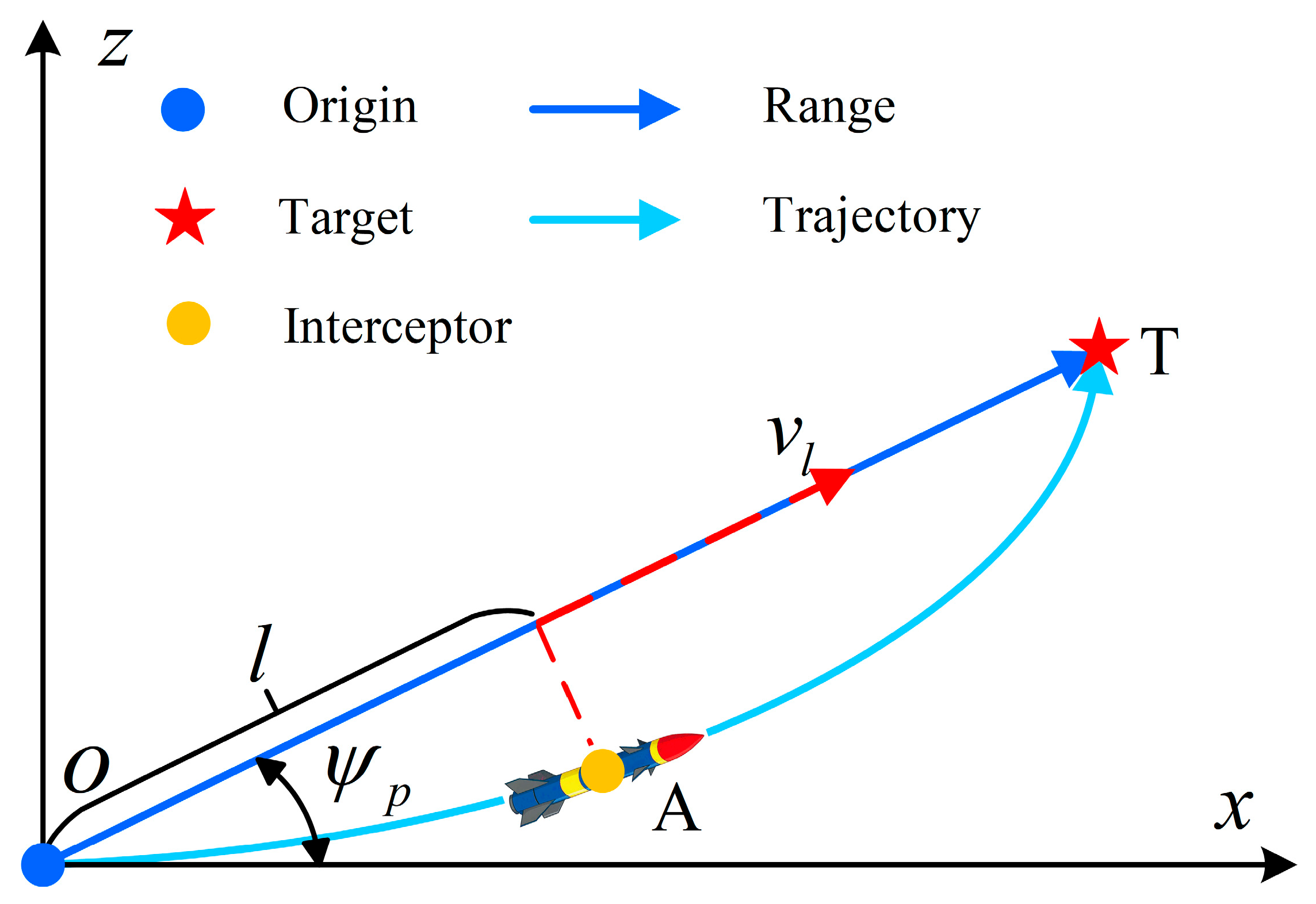
Section 2 formulates the optimal control problem for an aerodynamically controlled interceptor in the range domain.
Section 3 develops an improved SOCP model.
Section 4 presents the implementation of the variable-discrete-scale scheme.
Section 5 validates the proposed method under both large discrete-scale and variable-discrete-scale conditions.
Section 6 concludes the paper, followed by appendices
3. Improved SOCP Problem Description
In this section, the non-convex optimal control problem is first convexified into an SOCP formulation. Subsequently, equal-scale discretization is performed. Finally, an improved SOCP model is developed to overcome both the stringent terminal constraints and Hessian matrix singularity encountered during the solution.
3.1. SOCP
The non-convexity of the optimal control problem originates from three sources: the affine state equations, path constraints, and control constraints. Through linearization of dynamic equations and path constraints, along with non-destructive convexification of control constraints, the problem can be transformed into an SOCP.
Let
denote the
k-th iterative solution of the optimization problem. The dynamic Equation (7) is then linearized with respect to
.
where
; see
Appendix A for details.
The path constraints (11) are linearized with respect to
, yielding
where
represents the derivative of the path constraints with respect to the
k-th iteration solution
, and
defines the maximum allowable value of the
i-th path constraint. To ensure effective linearization, a trust region is introduced.
where
is a constant vector.
The non-convexity in the control constraint arises from the second-order cone constraint (8). This constraint can be non-destructively convexified through control relaxation, as follows:
The control constraint relaxation, being a second-order cone constraint (18), may cause relaxation inaccuracies. To resolve this, a regularization term is incorporated into the objective function as follows [
25]:
The optimal control problem P0 is convexified to SOCP, as shown in Problem P1.
3.2. Discretization
The problem P1 is a continuous-time SOCP. The distance domain is discretized using an equidistant scale in this section. Through this discretization, the infinite-dimensional Problem P1 is transformed into a finite-dimensional SOCP model, with all state constraints being normalized.
The distance domain variable
is an independent variable of Problem P1. Given
discrete points, these points are denoted as
and
. The discrete scale is represented by
, while the inter-point relationship is characterized by
and
. Based on these definitions, the following is obtained:
The dynamic equation is discretized by the trapezoidal method.
where
,
,
,
,
.
A simplified Equation (23) is available:
where
,
,
,
,
.
The parameters
and
are defined as follows:
and
. By simplifying the simultaneous Equation (24) and incorporating the initial boundary conditions (12), the equality matrix constraint (25) is obtained.
where
and
represent the coefficient matrix and the constant-term vector of the equation, respectively.
Then, the discretization of the path constraint (16), control constraint (19), trust region (17) and objective function (20) is carried out in turn. The discretized path constraint and control constraint are combined to obtain a second-order cone constraint (24) and inequality matrix constraint (25).
where
and
represent the inequality coefficient matrix and the inequality constant vector, respectively.
Additional constraints can also be expressed at discrete points. Through this transformation, the SOCP Problem P1 is converted into the discrete formulation P2:
3.3. Improved SOCP
To enhance the convergence speed of the SCP method while addressing stringent terminal constraints and matrix singularity issues, an improved SCP approach is proposed. Key improvements feature terminal error-proportional relaxation, an implemented variable trust region, and path normalization.
3.3.1. Terminal Error-Proportional Relaxation Method
Under complex dynamics and multiple path constraints, strict terminal equality constraints may lead to the non-existence of feasible solutions, and the computational efficiency of handling equality constraints is lower than that of inequality constraints. To address this issue, slack variables are introduced [
30]. Due to the significant difference in the numerical ranges between the position states and the angle states, a terminal error proportional relaxation method is proposed based on the physical characteristics of the state variables. This method transforms the hard constraints of strict terminal equalities into soft constraints that gradually converge with slack variables under different weights, overcoming the shrinkage of the feasible solution space and trajectory divergence caused by strict equality constraints.
The relaxed terminal constraint (12) takes the following form:
where
and
represent the coefficients of the relaxation variables of the distance term and the angle term, respectively, which can be selected according to the magnitude of the normalized variables;
is the relaxation variable of the corresponding parameter, and
is added to the objective function to constrain. When
, the effect of the equality constraint
can be achieved in the objective function. For ease of expression, the expression (29) can be converted to
3.3.2. Variable Trust Region
Compared with fixed trust regions, a variable trust region strategy allows for the expansion of the trust region when poor initial estimates are encountered, thereby facilitating the identification of feasible solutions. As the model solution approaches optimality, the trust region is automatically reduced to accelerate convergence. The variable trust region constraints are formulated as follows:
where
is the trust region relaxation variable. Add
to the objective function to constrain the trust region range.
3.3.3. Path Normalization
The path constraints exhibit a significantly larger magnitude than the state variables, resulting in a substantially greater maximum eigenvalue than minimum eigenvalue in the Hessian matrix. This large condition number, particularly for large-scale problems, causes the matrix determinant to approach zero, leading to near-singularity and potential solution failure. To address this, the path constraints are normalized as follows:
where
and
.
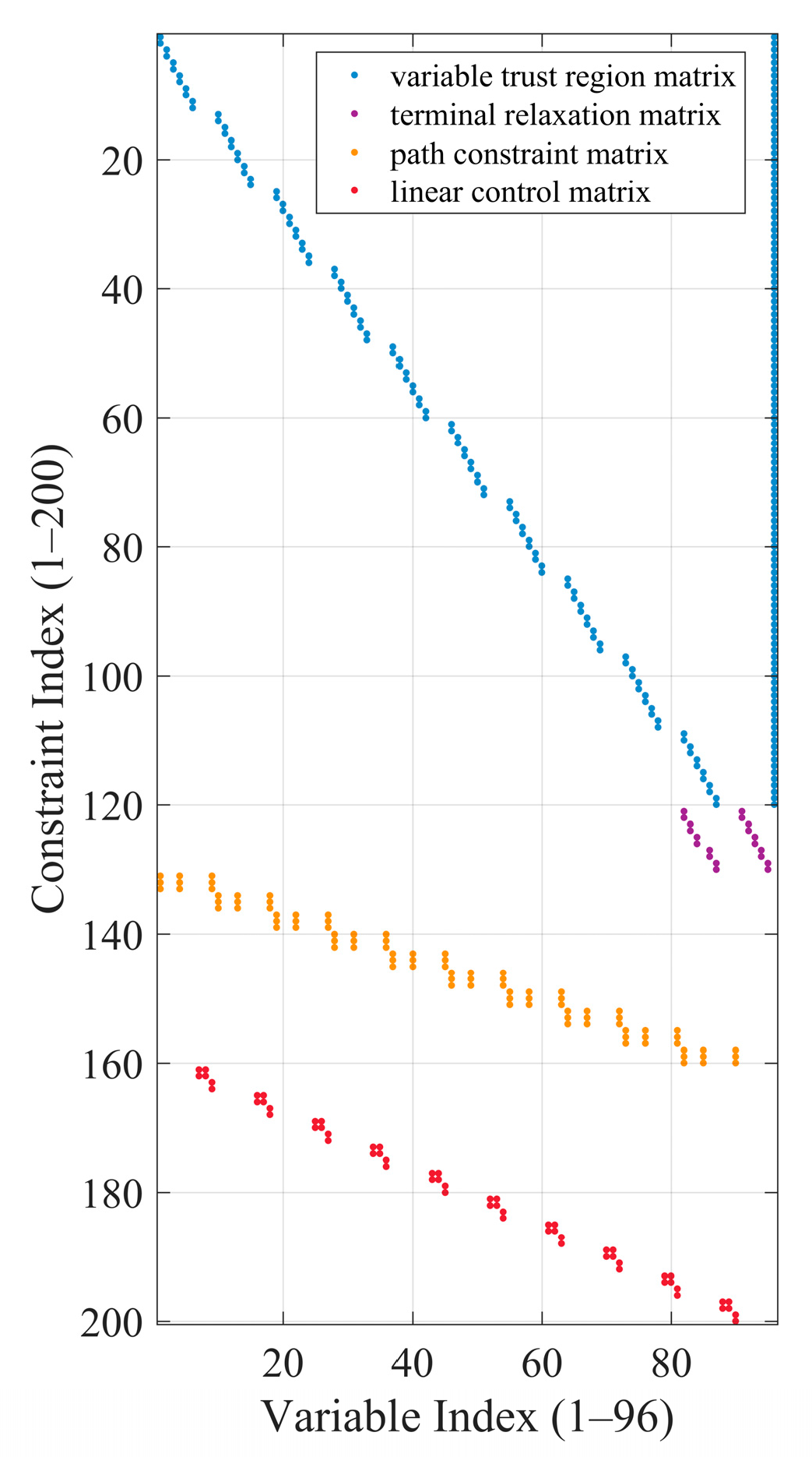
By integrating the terminal-relaxation constraint (30), the variable trust region constraint (31), the path constraint (32), and the inequality matrix constraint (27) under the condition of , a new inequality matrix constraint is formed. Based on these consolidated constraints, the original SOCP (Problem P2) is transformed into an improved formulation, designated as Problem P3.
P3:
where the equation coefficient matrix
, constant term vector
, inequality coefficient matrix
, and inequality constant term vector
are provided in
Appendix B.
4. Variable-Discrete-Scale SCP
In this section, an initial trajectory generation method is first presented. Subsequently, an SCP framework with a variable discretization scale is proposed. Finally, while maintaining solution accuracy, the computational speed is enhanced through the introduction of a scale adaptation method.
4.1. Initial Trajectory
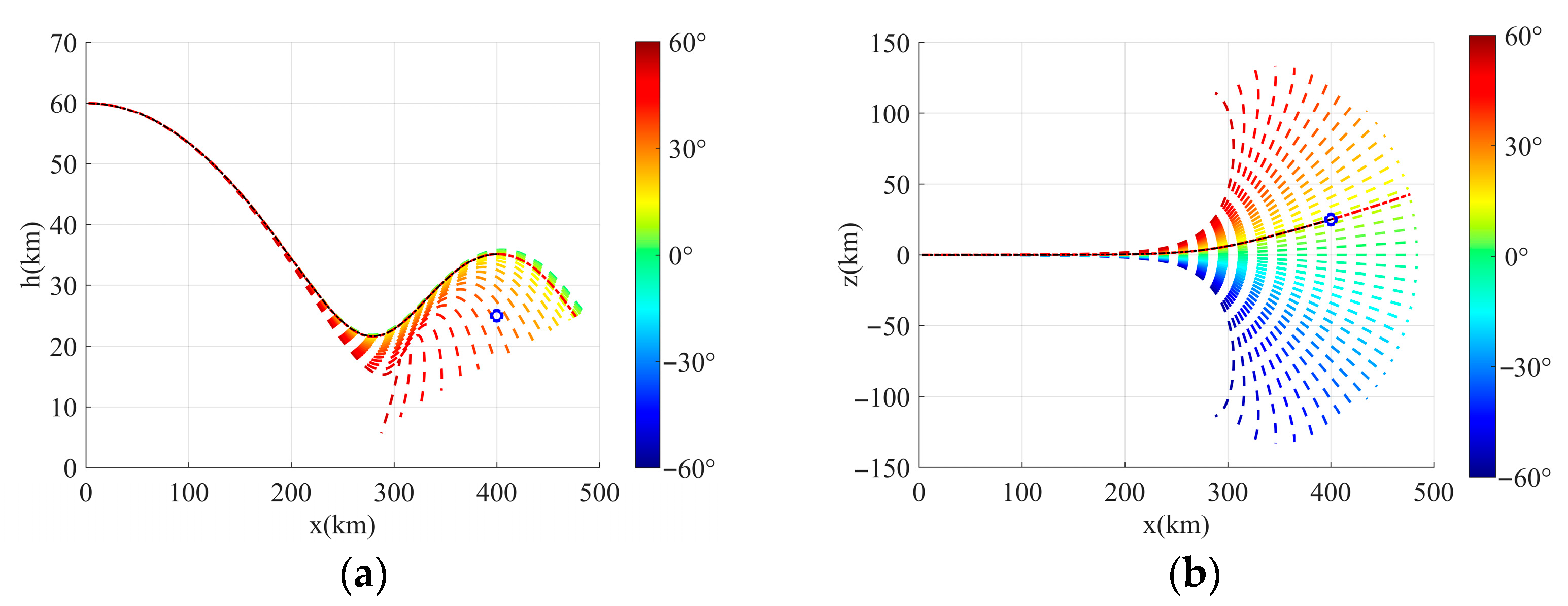
The initial trajectory is generated using normalized maximum lift coefficients and varying inclination angles. A trajectory group is then obtained by interpolating between the two trajectories nearest to the terminal position in lateral distance. The specific implementation steps are as follows:
Step 1: Select the normalized coefficient and bank angle as control variables. Assuming that the terminal time is the termination time, the trajectory groups are generated by integrating the interval time , where is selected in in proportion to .
Step 2: Select the trajectory
and
that are closest to the terminal position
in the trajectory group
.
and
can be obtained according to the serial numbers of the distance interpolation
and
obtained by Equation (34),
. The bank angles corresponding to
and
are
and
. According to Equation (35), the bank angle
is obtained.
Step 3: Select and bank angle as the control quantity and integrate the trajectory. Then, the initial range domain trajectory of the required discrete scale is interpolated.
4.2. SCP with Variable-Discrete-Scale Framework
The variable-discrete-scale method is implemented by first employing a coarse discretization for rapid trajectory solution, followed by conversion to a fine discretization for higher-accuracy results. The SCP with variable-discrete-scale framework is presented in Algorithm 1.
| Algorithm 1: SCP with variable-discrete-scale framework |
Input: Initial guess trajectory , trust region , convergence region , , , , ;
Output: and |
For i = 1 to 2
If
Set , ;
Else
Set ,;
End If
While do
Solve problem P3 to get and ;
If then
Break;
Else
;
Set ;
End If
End While |
| End For |
4.3. Adaptive Variable-Discrete-Scale Algorithm
The SOCP Problem P4 is solved through discrete iterative approximation. The converged iterative solution is discrete, resulting in trajectory integration errors when the control variables are implemented. When the mesh is fixed, the accuracy of the convergence solution depends on the discrete scale. The accuracy, efficiency and convergence speed of the discrete solution are closely related to the grid, convergence accuracy and problem form.
To balance accuracy and convergence, a residual-based adaptive variable-discrete-scale algorithm is proposed. After the
k-th iteration converges, the integral terminal state of the
j-th discrete scale is
The absolute value of the
j-th discrete-scale residual of the
i-th state is
Due to varying magnitudes across different states, a uniform error metric cannot be applied. Therefore, the residual is normalized according to each state’s individual scale.
where
denotes the
i-th state (
i = 1, …, 6) of the
k-th converged solution, while
represents the range between the maximum and minimum values in the
i-th state of this solution.
The relative residual of the
j-th grid of the
i-th state is
A large local relative residual indicates strong nonlinearity at the current discrete scale, necessitating increased point density and reduced scale in the region. Conversely, small residuals reflect weak nonlinearity, allowing discrete point reduction and scale enlargement to enhance computational efficiency. Based on this principle, an adaptive variable-discrete-scale strategy is proposed.
Suppose that the allowable lower limit of the local relative residual error is
, the maximum value of the local relative residual error is
, and the sequence vector
is
The number of discrete intervals to be processed is the number of elements in . When condition is met, discrete-scale merging is executed based on relative residuals. The complete procedure is presented in Algorithm 2.
The local discrete interval elimination rule can be defined as scale merging when the sum of adjacent relative residuals falls below the allowable lower limit
. Given an upper limit
for local relative residuals, the discrete scale reduction rule is specified as follows:
The range domain is updated by using scales instead of .
The implementation rules for adaptive variable discrete scaling are established by Algorithm 2 and Equation (41), with optimization being performed at large discrete scales.
| Algorithm 2: Local discrete interval adjustment algorithm based on relative residuals |
Input: , , , , , N;
Output: Mesh length ;
Set ;
While i < do
If then
← + ;
← 0;
Set i ← i + 1;
End If
Set k ← i, ;
If i < then
While = do
← + ;
← + ;
;
Set i ← i + 1;
If ( > )||(i == )||() then
Set i ← i + 1;
Break;
Else If
End While
Else if
End While
if (i ≤ ) && ( ≠N) then
← + ;
← 0;
End if
Return ; |
5. Numerical Simulations
The midcourse guidance parameters of the aerodynamically controlled aircraft are as follows:
,
,
,
. The constraint settings of midcourse guidance are as follows:
,
,
,
for the path constraints in Equation (10);
,
for terminal relaxation in Equation (29); and
,
,
,
for the objective function in Equation (33). The parameters generated by the initial trajectory of the range domain are as follows: terminal time
, integration intervals
, and bank angle selection increments of
. The initial and ideal terminal conditions are shown in
Table 1. The trust region
;
; the convergence region
. The lower limit
and upper limit
for the local relative residual error are set to
and
, respectively.
All simulations were conducted on a laptop computer with an Intel Core i7-1165G7, 2.80 Ghz, 16 G RAM, and Windows 10 operating system. The subproblems of SCP are solved by ECOS [
38] in version 2.0.8.36.
The integral trajectory is obtained by trapezoidal integration on 40,000 equidistant nodes, taking the optimized control sequence as the control quantity. The accuracy of the optimization method is evaluated by comparing the optimization solution with product decomposition and ideal terminal.
5.1. Large Discrete-Scale Optimization
This section first simulates the initial trajectory in the range domain, which serves as the initial guess for the SCP, followed by a large-discretization-scale optimization simulation.
In
Figure 2, the generated trajectory cluster, integral trajectory, and interpolated initial range domain trajectory are obtained with a computational time of 0.049 s. The interpolated initial trajectory demonstrates spatial consistency with terminal constraints in the range and longitudinal position, rendering it suitable as an initial iterative solution for SCP.
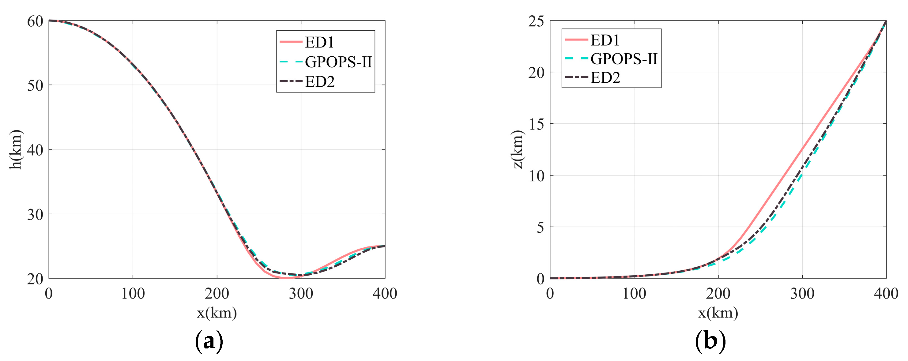
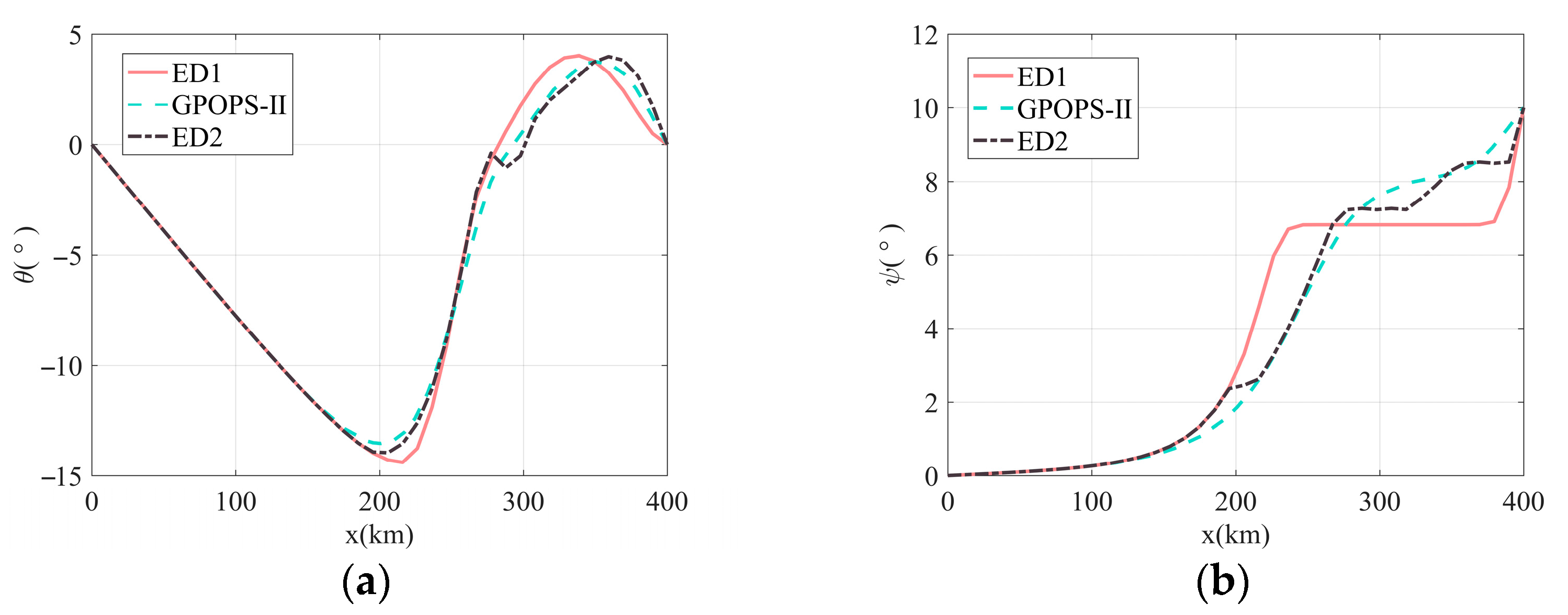
Large-discrete-scale optimization refers to discretizing the midcourse guidance phase into equally spaced large-scale segments for optimization. The optimized results can serve as the first layer of the variable-discrete-scale SCP for midcourse guidance. For comparison, we employ large-discrete-scale SCP (ED1 denotes solving the SOCP with only terminal error proportion relaxation, and ED2 represents solving the improved SOCP and the software GPOPS-II (v5.1) to solve Problem P0.
Due to strict constraint conditions, SCP fails to solve the SOCP of the terminal equality constraint (12).
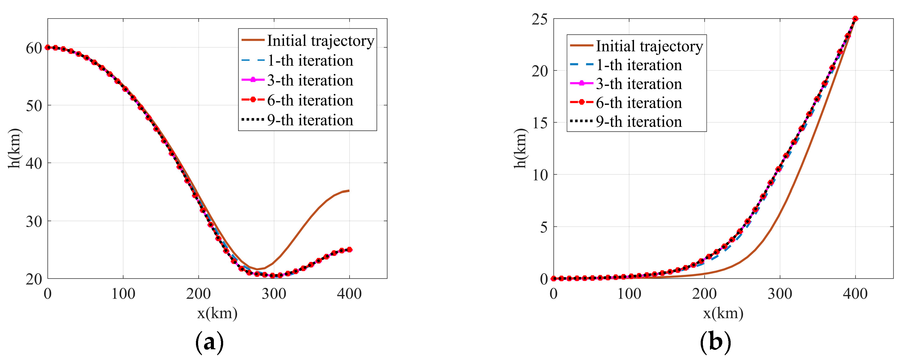
Figure 3 presents the convergence after 9 iterations when solving the improved SOCP. The results in
Figure 4 and
Figure 5 indicate that these three methods have reached the expected terminal state and realized the trajectory planning, which shows the effectiveness of the terminal error proportional relaxation method.
Table 2 demonstrates that SCP exhibits significant advantages over GPOPS-II in CPU time for large-scale discrete trajectory optimization, with the improved SOCP solution time accounting for merely 5.4% of that required by GPOPS-II. The computation time for the improved SOCP is 37.2% of that required by the terminal error proportion-relaxed SOCP. The total computation time for the first-layer solution of the variable-discrete-scale SCP in midcourse guidance is 0.345 s.
Table 3 presents the solution accuracy of different methods for the midcourse guidance problem. The SCP with ED1 yields the poorest accuracy with a maximum state error of approximately 10.9‰. In comparison, GPOPS-II and SCP with ED2 achieve significantly better performance, demonstrating maximum state errors around 7.2‰ and 8.8‰, respectively. The superior accuracy of ED2 compared to both ED1 primarily stems from its normalized path constraints, which exhibit smaller magnitude differences relative to other state constraints. This effectively prevents the neglect of minor constraint errors, thereby enhancing overall solution precision.
5.2. Variable-Discrete-Scale Optimization
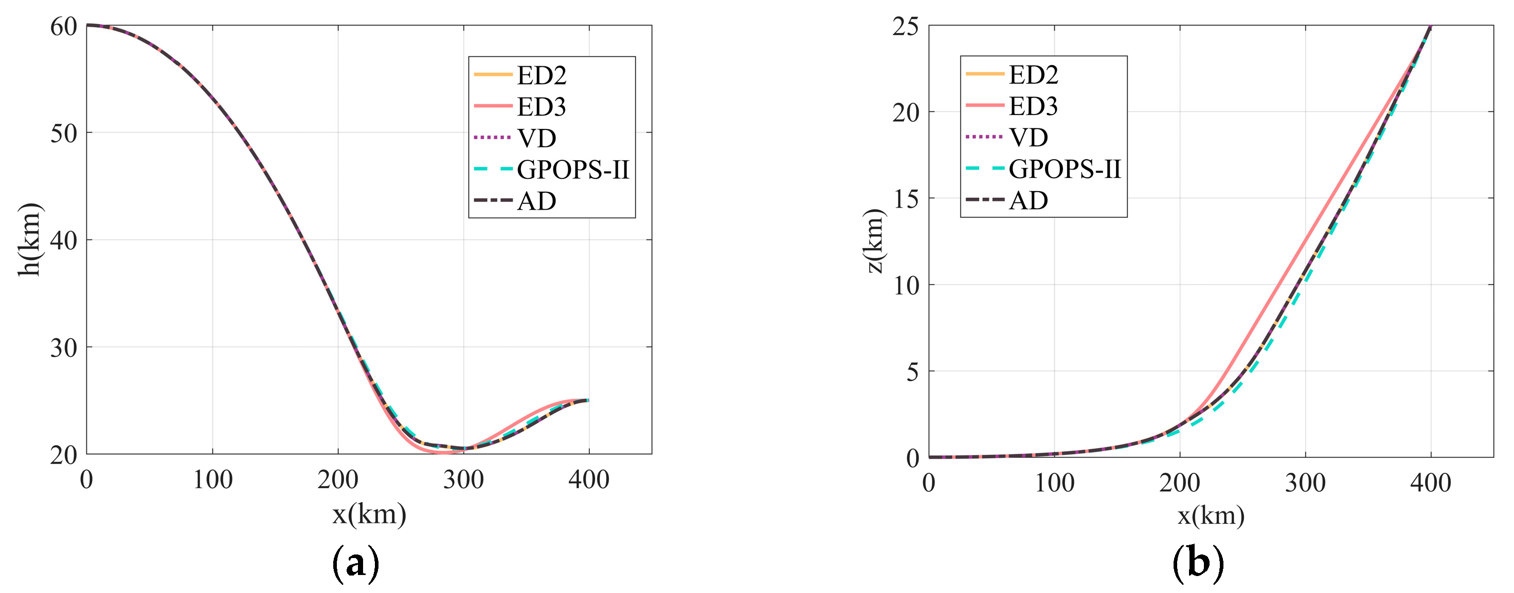
For comparative analysis, we employ improved SOCP-based SCP (where ED3 denotes equidistant small-scale discretization, while VD and AD represent variable-discrete-scale and adaptive variable-discrete-scale optimization, respectively) along with the software GPOPS-II to solve Problem P0. In the variable-discretization-scale simulation of this section, the ED2 solution is employed as an initial guess to further refine the optimization results obtained from the SCP method. Note that the condition is applied here.
Figure 6 and
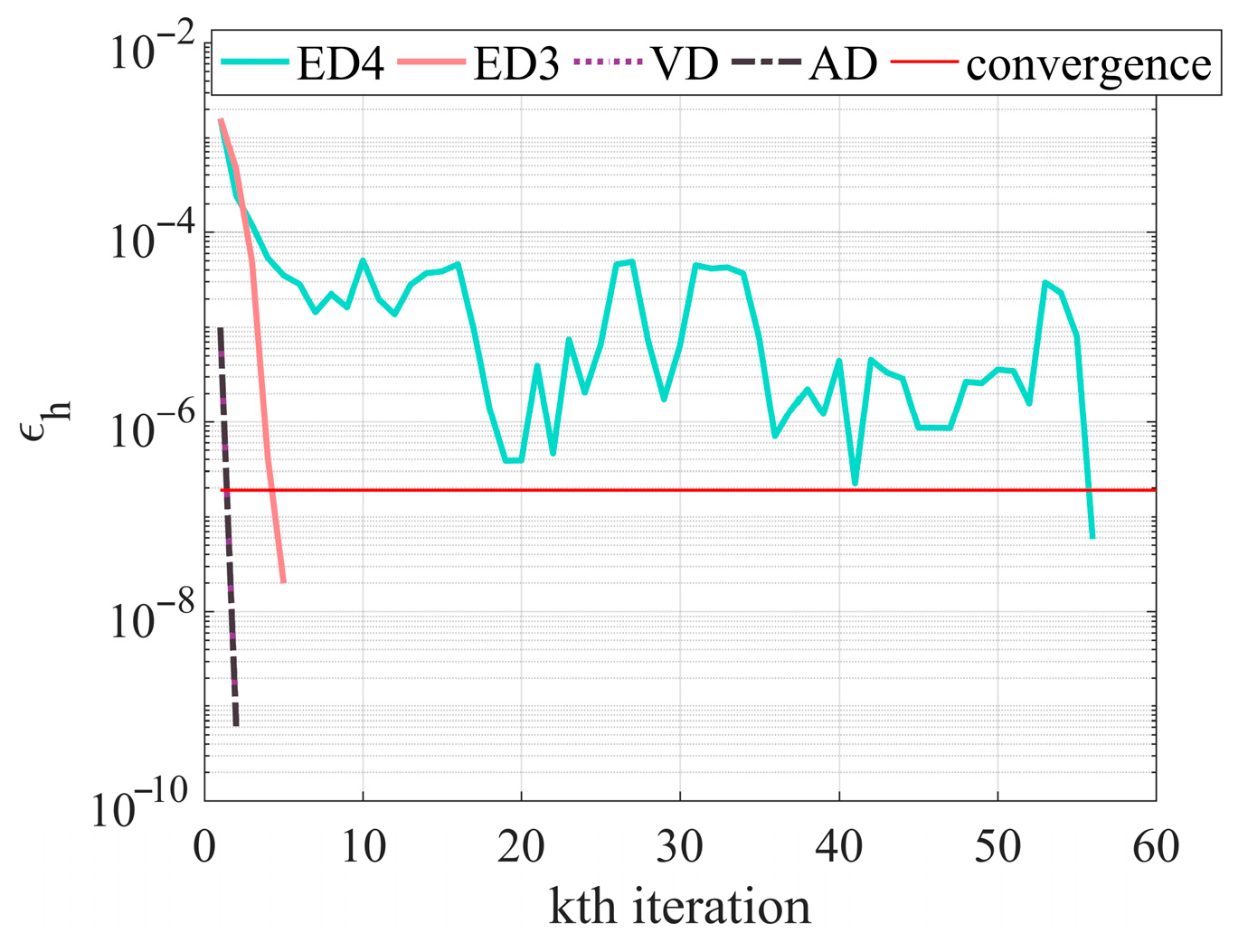
Figure 7 compare the solving results of different schemes, all of which satisfy the process constraints and achieve the specified terminal states. It is noteworthy that although the SOCP with only terminal error proportional relaxation (named ED4) successfully generates a trajectory, it converges only after 56 iterations.
Figure 8 shows the maximum iteration intervals in altitude for the four SCP solutions. Among them, the SCP of ED4 exhibits significant oscillations and a notably increased number of iterations. This is due to the absence of an acceleration convergence term, as well as the increase in the number of discrete points and the expansion of the matrix scale. Both VD and AD benefit from favorable initial guesses, resulting in reduced maximum iteration intervals.
As can be seen in
Table 4, for large-scale problems, SCP does not necessarily outperform GPOPS-II in terms of computational efficiency, as observed in ED4. However, compared with GPOPS-II, SCP with convergence acceleration terms, such as ED3, VD, and AD, demonstrates higher computational efficiency. The total computation times for ED4, ED3, VD, and AD are 57.747 s, 5.413 s, 1.645 s, and 1.643 s, respectively. The computation times of the latter three, which employ the improved SOCP formulation, are all less than one-tenth of that of ED4. Among the improved SOCP methods, the total computation times required for VD and AD to successfully generate trajectories account for only 30.39% and 30.35% of that of ED3, respectively, demonstrating the effectiveness of the variable-discrete-scale method.
Table 5 compares the terminal state errors and maximum state errors between the optimization results and the integration results for different methods. The simulation results for SCP(ED4) indicate that an increase in the number of iterations does not necessarily lead to improved accuracy. In terms of position accuracy, the terminal state error of SCP(AD) is the smallest, which is 81.2% higher than that of SCP(ED3) and better than that of GPOPS-II. Furthermore, a strong correlation was observed between the terminal state error and the maximum state error in the range, x (which effectively represents the downrange distance in the simulation), particularly for the terminal position error. When the maximum state error in the range domain is small, the terminal state error also decreases significantly. The underlying mechanism for this phenomenon can be attributed to deviations in the dynamic response over the range domain, which lead to a phase shift in the control profile. This timing-like misalignment accumulates along the flight path, manifesting as lateral or longitudinal deviations in the state trajectory and resulting in peak errors at certain range points, ultimately compromising the convergence accuracy of the terminal state. Collectively, these experiments demonstrate the advantages of the improved SOCP model and the variable discretization scaling strategy in terms of both computational efficiency and solution accuracy.
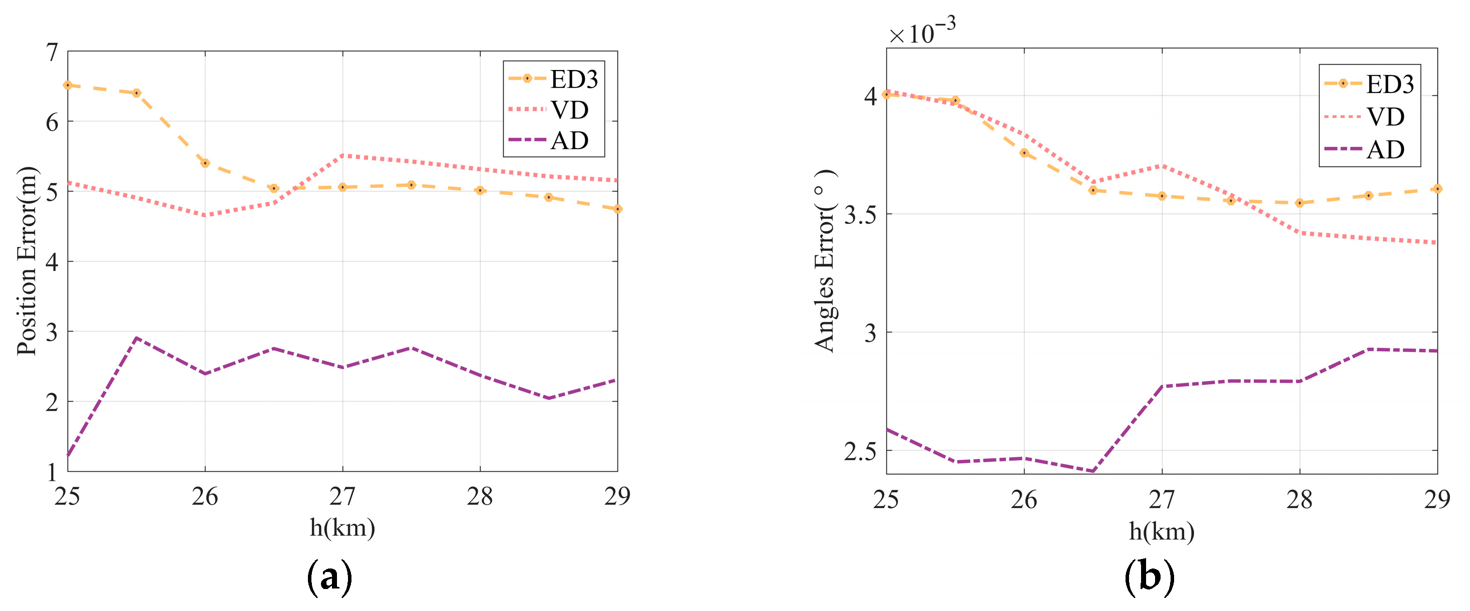
Figure 9 illustrates the variations in the total terminal position error and total terminal angle error with respect to altitude. Simulation results indicate no clear correlation between terminal state errors and altitude. Among the methods presented in this paper, the improved SOCP method with a VD strategy exhibits terminal state errors comparable to the baseline improved SOCP. In contrast, the AD achieves a significant reduction in terminal errors. This demonstrates that the VD approach, by leveraging a more accurate reference trajectory, enhances computational efficiency without compromising solution accuracy. Furthermore, the AD strategy effectively balances computational cost and precision.
6. Conclusions
This paper presents a variable-discrete-scale SCP for midcourse guidance trajectory design of aerodynamic control interceptors. The improved SOCP model incorporates three key techniques: terminal error relaxation, variable trust region, and path constraint normalization. This integration leads to a reduction in the number of iterations. A variable-discrete-scale optimization framework is proposed to enhance both trajectory solution accuracy and computational efficiency. Numerical simulation results indicate that the proposed method delivers a solution accuracy comparable to GPOPS-II. However, the computational time required is reduced to less than one-tenth of that of GPOPS-II under large discretization scales. For small-scale discretization optimization, an adaptive variable-scale discretization framework is adopted. The proposed algorithm demonstrates a solution accuracy that is comparable to that obtained by GPOPS-II. The computational time required is only 30.4% of that needed by small-scale discretized SCP under the same model. Furthermore, the proposed variable discretization optimization framework exhibits strong versatility for generating high-precision trajectories and is straightforward to implement.
The proposed improved SOCP model employs a variable trust region method to determine the iteration step size, which increases computational complexity and reduces single-iteration efficiency. In the next step, a line search algorithm will be adopted to optimize the step size determination process, thereby improving overall computational efficiency.

