Abstract
Hailstones exhibit variations in diameter and impact objects at different velocities influenced by airflow. The extent of damage inflicted by hailstorms is contingent upon both the size and speed of the hailstones. Accurately simulating hailstones is essential for conducting impact tests. In this research, artificial hailstones were created using a polyvinyl acetate (PVA) additive. Previous investigations indicate that a mixture comprising 12% PVA and 88% demineralized water is most effective in replicating the behavior of natural hailstones. The primary objective of this study is to establish an experimental setup for assessing the impact of hailstones on aircraft canopies. To support this goal, specific requirements for impact testing were outlined. Dynamic impact tests were conducted using two different aircraft dimensions. Artificial hailstones of 20 mm and 50 mm in diameter were successfully manufactured for the experiments. The designated velocities for these artificial hailstones were 20 m/s, 30 m/s, 60 m/s, and 120 m/s, for which the necessary air pressures were calculated. Experimental results confirmed that artificial hailstones of varying diameters could be effectively produced and that they impacted predetermined areas on the aircraft canopies. However, the study also found that artificial hailstones traveling at velocities exceeding 120 m/s failed to produce visible deformation on the aircraft canopies.
1. Introduction
Hailstorms remain a significant concern across various sectors, particularly in aviation, due to their potential to inflict severe damage on aircraft structures. Hailstones, which can measure anywhere from a few millimeters to several centimeters in diameter, are propelled by dynamic atmospheric conditions, resulting in a wide range of impact velocities. The damage sustained by aircraft during hail-related incidents is largely dependent on the interplay between the size of the hailstones and their velocity upon impact. As such, understanding and accurately simulating hailstone characteristics is essential for conducting effective impact tests relevant to aviation safety. Past research has established that creating artificial hailstones that closely mimic the properties of natural hail is critical for testing the resilience of aircraft canopies. One effective method has been the use of polyvinyl acetate (PVA) as an additive in the formation of artificial hailstones. Studies suggest that a combination of 12% PVA and 88% demineralized water yields the most accurate representation of natural hailstone dynamics. This knowledge provides a valuable foundation for innovations in experimental design concerning impact testing.
Hailstorms are serious natural disasters that can inflict considerable damage on various types of infrastructure, including roofs, vehicles, and aircraft. On 27 July 2017, a hailstorm in Turkey impacted 180,000 cars, resulting in estimated damages of 1 million TL. Besides damaging property, hailstorms can also be deadly; for example, one fatality occurred in Italy due to hail. Climate change has intensified numerous natural events, and recent observations indicate an increase in both the frequency and size of hailstones [1]. Raupach et al. [2] predict a rise in the occurrence of hailstorms in Australia and Europe, while their frequency may decline in Asia and North America. These forecasts emphasize the growing necessity of investigating the impacts of hailstorms. Aircraft, vital for both commercial travel and military operations, are not exempt from hailstorm effects. Such storms can cause significant damage to planes, compromising their structural integrity and the safety of passengers. On 9 June 2024, a major hailstorm severely damaged an Airbus A320 flying from Mallorca to Vienna, as shown in Figure 1 [3]. Given the critical importance of airplanes in both civilian and military arenas, it is essential to understand the effects of hail on aircraft to enhance safety protocols and advance more robust aviation technologies.
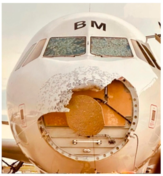
Figure 1.
The effects of hail impact (www.mediadrumimages.com) [3].
Simulating hailstones is crucial for understanding their behavior during impact tests. Researchers have employed various materials and techniques to replicate natural hailstones. Niemeier and Burley [4] initially utilized actual natural hailstones for their studies. Johnson and Schaffnit [5], Nomura et al. [6], Fleming et al. [7], and Shi et al. [8] implemented steel and other indenters in their experiments. Flüeler et al. [9] conducted impact tests with polyamide balls and ice balls produced from demineralized water. Schulson [10] developed layered artificial hail by immersing demineralized water in carbon dioxide, resulting in hailstones with an oval rather than a spherical shape. This oval shape presents challenges for control in research. The carbon dioxide layer weakens the outer ice, which leads to breakage upon impact. Liang and Ramsay [11] created artificial hailstones using deionized water, with test results indicating that the presence of cracks and air pockets in these stones contributed to their failure. Swift [12] attempted to enhance the extensibility of ice balls by incorporating cotton, but this method did not preserve structural integrity during high-velocity impacts. To improve the strength of artificial hailstones, Uz et al. [13] tested various ratios of PVA and microfiber. Their findings, detailed in Table 1, indicated that a formulation of 12% PVA and 88% demineralized water achieved the highest integrity. A novel method for producing artificial hailstones was also developed.

Table 1.
Hail Strike Test Identification.
The primary aim of this study is to develop an experimental framework for investigating the impact of hailstones on aircraft canopies, specifically focusing on the effects of varying hailstone diameters and velocities. As part of this effort, requirements for conducting rigorous impact tests have been systematically identified and implemented. To thoroughly assess the implications of hailstone impacts, a range of artificial hailstones with diameters of 20 mm and 50 mm have been produced, along with meticulously calculated target velocities of 20 m/s, 30 m/s, 60 m/s, and 120 m/s.
This study’s findings are anticipated to offer significant insights into the impact behavior of artificial hailstones, thus contributing to the broader understanding of the effects of hailstorms on aviation safety. By examining the correlation between the characteristics of artificial hailstones and the resultant damage on aircraft canopies, this research will not only enhance our understanding of hailstorm impacts but also pave the way for developing more resilient aircraft designs.
2. Canopy Structure of the HÜRKUŞ-II
The HÜRKUŞ-II canopy structure is an integral component of the aircraft, designed to provide both structural integrity and enhanced safety for its pilots. At its core, the canopy consists of a robust metallic frame constructed from aluminum alloys, as given in Figure 2. This choice of material is pivotal: aluminum alloys offer an optimal balance between strength and weight, which is critical in aviation applications where minimizing weight is essential for performance and fuel efficiency. The aluminum frame supports the entire canopy assembly and is engineered to withstand the aerodynamic forces experienced during flight, ensuring durability and resilience under various environmental conditions. Additionally, the corrosion-resistant properties of aluminum contribute to the longevity of the canopy, reducing maintenance needs and enhancing the aircraft’s lifecycle.
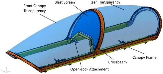
Figure 2.
Canopy General Description.
Complementing the metallic frame is the center bow, which showcases advanced composite technology with a design utilizing carbon fiber prepegs infused with phenolic resin. This composite structure leverages the high strength-to-weight ratio of carbon fiber, making it a superior alternative to traditional materials. The carbon fiber prepegs provide significant tensile strength while remaining lightweight, which enhances the aerodynamic properties of the HÜRKUŞ-II without adding unnecessary bulk. The phenolic resin contributes to the structural integrity of the bow by offering excellent thermal stability and resistance to chemical and moisture degradation. This strategic use of composite materials not only consolidates the structural reliability of the canopy but also allows for a streamlined design that optimizes aerodynamics.
The canopy comprises two distinct transparencies: a front transparency and a rear transparency, which are seamlessly integrated into the single-piece frame of the canopy. This integration is essential for maintaining clarity and visibility for the pilots, as high-quality optical-grade acrylic or polycarbonate materials are generally used to achieve unobstructed views from the cockpit. Such visibility is crucial for situational awareness during flight operations, particularly in a training environment. Furthermore, a noteworthy safety feature included in the canopy design is a blast screen made from durable polycarbonate. This screen is strategically positioned between the center bow and the crossbeam, serving a critical role in protecting the rear pilot during seat ejections. If the front pilot needs to eject, the blast screen acts as a shield against the force and potential debris, ensuring that the rear pilot remains safe and secure. The overall configuration and material selection in the HÜRKUŞ-II canopy illustrate a comprehensive approach to combining safety, functionality, and performance, making it a remarkable asset in modern aviation design.
3. Requirements
The Turkish basic and primary training aircraft (TBTEU) project includes the Hürkuş aircraft, which has been designed and developed by Turkish Aerospace Industries, Inc. (TAI) in accordance with NATO standards. Test method (TBTEU-5210-FWS-134) describes evaluating the impact resistance of aircraft canopies to various types of projectiles, including hailstones. The requirements for the Canopy Assembly by Volo Composites & Engineering Ltd., Ankara, Turkey [14] are outlined in TBTEU-5210-FWS-134, which stipulates that the assembly must withstand hail impacts from hailstones with diameters of 20 mm and 50 mm. These hailstones will have a density of 0.9 g/cm3 and are expected to strike with a terminal velocity of 20.8 m/s while the aircraft is traveling at a flight velocity of 200 KEAS. It is important to note that the flight speed of 200 KEAS corresponds to 200 knots true air speed at sea level. However, at an altitude of 20,000 ft AGL (FL200), this speed translates to approximately 275 knots true airspeed (~141 m/s). The performance of the canopy under these conditions must align with the acceptance criteria specified in TBTEU-5210-FWS-135 to ensure it meets operational safety standards [15]. In this study, it is important to clarify that the reference point for the 200 KEAS speed is based on a sea-level standard day.
Furthermore, TBTEU-5210-FWS-135 states that the canopy must not exhibit any cracks, delamination, or other defects that could compromise the safety of the aircraft during landing. Any failure to meet these criteria could lead to hazardous conditions, highlighting the critical importance of the canopy assembly in maintaining the overall safety of the aircraft. A thorough assessment of the canopy’s resistance to hail impact is necessary to ensure it meets these stringent safety requirements.
Specimen Conditioning
The conditioning of test specimens is essential for ensuring reliable and reproducible results in hail strike tests. The tests will be conducted at a controlled temperature of 20 °C ± 5 °C, simulating typical environmental conditions that the material may encounter in real-world applications. In accordance with MIL-PRF-8184 [16], Elastomeric Polymers and Rubber Materials for Airframe Seals, this standard specifies the required properties, performance, and testing procedures. Materials used in aerospace applications must withstand harsh environmental and mechanical conditions. To maintain the integrity of the PMMA plates, which conform to the specifications outlined in MIL-PRF-8184, NV83, the test coupons will be delivered in a square size of 660 mm × 660 mm, protected by original plastic foil. A detailed Dimensional Verification Inspection (DVI) will be performed before testing to confirm that the specimens are free from any manufacturing or artificial defects. The protective foils will be removed immediately prior to the hail impact shots to ensure the specimens are exposed to their true condition, eliminating any contaminants that could affect the results.
The PMMA (polymethylmethacrylate) plates will have a specific thickness of 11.5 ± 1.27 mm, ensuring that test results accurately reflect the material’s performance in applications where it encounters hail impacts. Adherence to these specifications is critical, as variations in thickness could lead to differences in impact resistance. For further insights on best practices in specimen conditioning, inspection, and testing protocols, refer to Volo Composites & Engineering Ltd. [17], which offers a comprehensive overview relevant to material science research and enhances the reliability of experimental results in this field.
4. Methods
Artificial hailstones were created using a composition of 12% PVA and 88% demineralized water, with the primary goal of enhancing their strength. Hailstones measuring 20 mm and 50 mm in diameter were utilized for the dynamic impact tests. Figure 3 shows the 20 mm and 50 mm diameter artificial hailstone casting molds employed in these tests. The experiments were carried out at impact velocities of 20 m/s and 30 m/s on aircraft canopies measuring 660 mm × 660 mm × 15 mm. For tests at 60 m/s and 120 m/s, canopies measuring 660 mm × 660 mm × 10 mm were used.
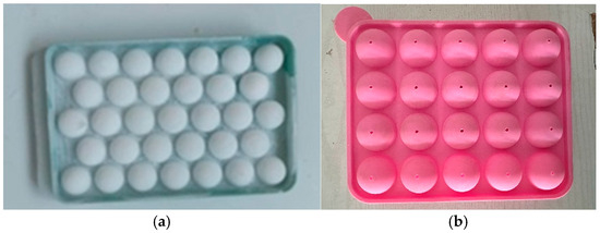
Figure 3.
Artificial hailstone with diameter of (a) 20 mm and (b) 50 mm.
Prior to conducting the impact tests, targets were marked on the canopy. A total of five shots were fired at each canopy. Subsequently, the canopy was positioned in the test area and securely fastened at its four edges, as illustrated in Figure 4. The hail gun is composed of an air tank, gas stopper, pressure gauge, and barrel. The air compressor supplies pressurized air, which is stored in the tank. Additionally, the air tank features a valve for releasing the stored air. The Hail and Hail Strike Test Laboratory at Adnan Menderes University was established by the first Author of this study in 2017 [15,17,18,19,20,21,22]. The laboratory team comprises four members, including Civil and Mechanical Engineers. The testing facility meets qualified global standards and is competitive on an international level by Turkish Aerospace Industries, Inc., Ankara, Turkey [23].
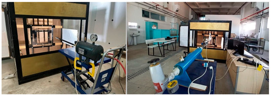
Figure 4.
Test Setup.
To validate the speed of the hail, a Radar Measurement Device intended for sports such as tennis and baseball has been procured for the Hail Shooting Test Laboratory at Adnan Menderes University. In this study, pieces of equipment are used such as Shooting Gage, which is especially manufactured for hail strike; Pressure Air Tank which is special manufactured for hail strike; Changeable Barrel (different hail dia.); Different Sizes and Storage Tanks for hail manufacturing; High Speed Camera (24000 FPS) (Chronos, Kron Technologies Inc., Burnaby, BC, Canada); Radar Speed Measurement Device (Sport Stalker Pro II+, Applied Concepts, Inc, Richardson, TX, USA); Air Chrony speed measurement device(AIR CHRONY s.r.o., Prague, Czech Republic); Digital Optical Micrometer observing surface defects.
Figure 5a shows the Sport Stalker Pro II+ device, which allows for measurements across a very wide range of speeds. During the experiments, the speed was verified using various methods with this device. First, numerous test shots were conducted with this device to ensure proper speed calibration. Due to its high sensitivity, this device in Figure 5a also measures the speed of water particles expelled by compressed air, which is why four openings with a diameter of 8 mm have been created at the end of the barrel to facilitate air exit. The holes in the barrel are illustrated in Figure 5b. The barrel diameter are length (L) set 0.007 m larger than the diameter of hailstone based on ASTM Standard F320-16 [22].
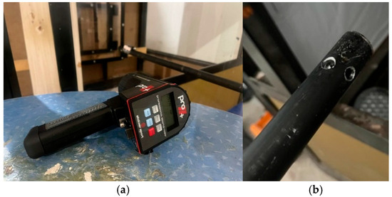
Figure 5.
Photos of (a) the Sport Stalker Pro II+ device and (b) Barrel for 20 mm diameter hailstone.
Air pressure was measured using a manometer. Before the impact tests, several test shots were fired to validate the pressure. Once the pressure was confirmed, the impact tests were conducted. Another important aspect of the test was measuring the velocity of the hailstones. The velocity was measured using a radar device, which tracks the velocity of the hailstone during its travel. The target velocities were 20 m/s, 60 m/s and 120 m/s for 20 mm diameters (D) of artificial hailstones and 30 m/s for 50 mm diameters of artificial hailstones. The distance from the barrel to the canopy was defined in ASTM F320-21 [24], and the tests were conducted accordingly. The test sample is installed with its horizontal axis as shown in Figure 6. In this study, to clarify, the tests were conducted using a flat plate cut from an actual canopy supplied directly by Volo Composites & Engineering Ltd. [14]. Using this approach, the curvature differences associated with actual canopy mounting could be accounted for while enhancing the rigidity of the hail rig when placed within the holding frames. To ensure more consistent results, the authors used a flat plate in order to eliminate variations caused by the curvature of a real canopy.
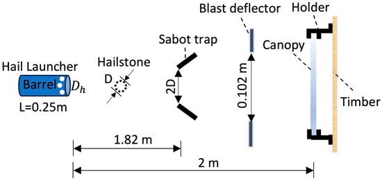
Figure 6.
Distance Between the Target and Barrel.
The 120 m/s test condition (approximately 230 knots) shows compliance with Volo Composites & Engineering Ltd. (2024)’s requirements for safety evaluation of canopy assembly design conditions. Certified testing equipment designed to launch ice spheres in a single shot within the specified speed range of 20 m/s to 120 m/s using pneumatic pressure. The setup is arranged vertically and features an interchangeable barrel to accommodate various ice diameters, as illustrated in Figure 7.
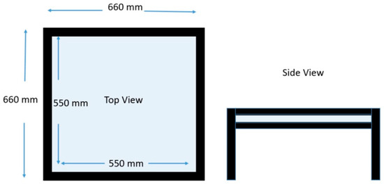
Figure 7.
View of Top and Side View of Representative Sample.
Hailstone scale coverage or initial storage in a freezer for a designated duration is frequently necessary. These methods are based on observations made in natural settings during actual hailstorms, aimed at creating a temperature shock and moistening. The speed of the ice projectiles is assessed using photovoltaic cells positioned at a specified distance from the blast deflector to the target, along with a timer. Position the edge of the windshield so that the center of the impact pattern is 71 mm from the specified point on the windshield edge, as illustrated in Figure 8.
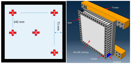
Figure 8.
Impact Pattern Location and Test Specimen Holder.
Three intact samples will be utilized for impact velocities of 20 m/s, 30 m/s, 60 m/s, and 120 m/s, with five shots conducted at the designated locations for each sample at the same velocity.
5. Results of the Impact Tests
The following points will be checked on the samples after each shot. If any crack is seen, it is not passed to next shot without evaluation and taking notes. To pass the hail strike test successfully, cracks, delamination or other defects that will prevent the safe landing of the aircraft shall not occur. The shot and parameter identification are listed in Table 1. A total of 20 shots were conducted on four canopies, and numerous pressure tests were performed.
Initially, the value of 20 m/s in impact velocity was targeted for the tests. The test results are given in Table 2.
Table 2.
Test results for 20 m/s.
The canopy remained undamaged, and no visible deformations were observed. Additionally, it was verified that there was no visible deformation using a Digital Optical Micrometer with a precision of 0.01 mm. The shooting images for selected two target points (highest and lowest velocities) from each shooting category are provided; however, due to length restrictions of the manuscript, all results are available for sharing upon request. With 0.4 bar and 0.3 bar, the average velocity was found to be 30.78 m/s. No visible deformation was observed, as given in Figure 9 and Figure 10.
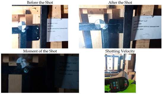
Figure 9.
S13 Shooting Images.
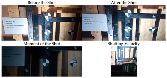
Figure 10.
S14 Shooting Images.
Another target velocity for the 20 mm diameter artificial hailstones was 60 m/s. Test results for 60 m/s of the impact velocity are given in Table 3. The average pressure required for this velocity was 0.9 bar. The test results show that the minimum velocity recorded was 51.11 m/s, and the maximum velocity was 60.83 m/s. While the test results demonstrated good correlation, the speed decreased in the last shot due to a drop in pressure. Although the difference in the first four shots was around 1.4%, the last shot showed a difference of 8%. Figure 11 and Figure 12 show the tests of S22 and S24 specimens before impact, after impact and the moment of impact including the velocity.
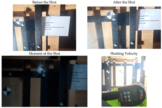
Figure 11.
S22 Shooting Images.
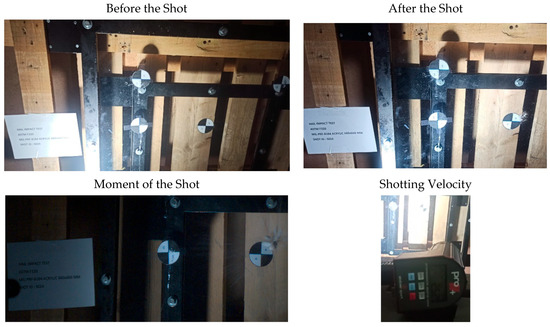
Figure 12.
S24 Shooting Images.
The final target velocity for the 20 mm diameter artificial hailstones was 120 m/s. The test results for 120 m/s are provided in Table 4.
Table 3.
Test results for 60 m/s (216 km/h).
Table 3.
Test results for 60 m/s (216 km/h).
| Test No | Diameter (mm) | Mass (g) | Density (kg/m3) | Pressure (Bar) | Velocity (m/s) | Visible Deformation-Canopy |
|---|---|---|---|---|---|---|
| S21 | 18.82 | 3.3 | 945.49 | 0.9 | 68.33 | No-Intact |
| S22 | 17.95 | 2.9 | 958.18 | 0.9 | 61.39 | No-Intact |
| S23 | 18.63 | 3.2 | 945.18 | 0.9 | 63.89 | No-Intact |
| S24 | 18.61 | 3.2 | 948.74 | 0.9 | 70.00 | No-Intact |
| S25 | 17.47 | 2.6 | 930.78 | 0.8 | 62.22 | No-Intact |
The average velocity recorded was 118.49 m/s, with the observed speed deviating by 1.26% from the target speed. In all impact tests, the artificial hailstones successfully hit the target without breaking. All canopies stayed intact and there is no visible deformation observed on the canopies.
Table 4.
Test results for 120 m/s.
Table 4.
Test results for 120 m/s.
| Test No | Diameter (mm) | Mass (g) | Density (kg/m3) | Pressure (Bar) | Velocity (m/s) | Visible Deformation-Canopy |
|---|---|---|---|---|---|---|
| S31 | 18.30 | 3.2 | 997.24 | 2.6 | 130.83 | No-Intact |
| S32 | 17.21 | 2.6 | 974.73 | 2.6 | 116.39 | No-Intact |
| S33 | 17.47 | 2.8 | 1002.38 | 2.6 | 130.56 | No-Intact |
| S34 | 18.70 | 3.3 | 963.29 | 2.6 | 128.89 | No-Intact |
| S35 | 18.44 | 3.1 | 944.24 | 2.6 | 119.72 | No-Intact |
For the 120 m/s tests, this is a critical point because the artificial hailstones were small and could be affected by higher air pressure. The shot numbered S-031 was successfully executed. A precise shot was made at the targeted point 1 in Figure 8. The situation before and after the shot is illustrated in Figure 13. Note that the shooting velocities displayed on the Sport Stalker Pro II+ device in Figure 13 and Figure 14 are 471 km/h (130.83 m/s) and 431 km/h (119.72 m/s), respectively.
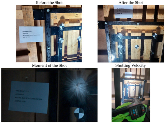
Figure 13.
S31 Shooting Images.
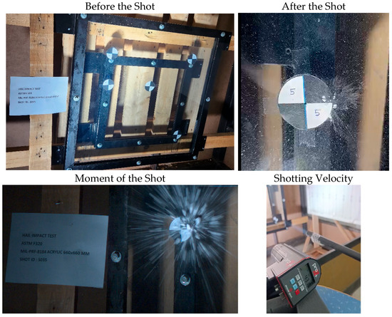
Figure 14.
S35 Shooting Images.
The hailstone experienced significant fragmentation upon impact due to its velocity exceeding the terminal velocity.
This situation demonstrated that the holes drilled at the end of the barrel prevented the hailstones from being damaged. In the final part of the study, 50 mm diameter artificial hailstones were impacted at 30 m/s. The average velocity for these shots was 33.22 m/s. The test results are provided in Table 5.
Table 5.
Test Results for 30 m/s.
As can be seen from Figure 15 and Figure 16, the size of the hailstone used in the shots named S42 and S45 is 50 mm. The hailstone remained intact following the impact at the lowest terminal velocity, demonstrating its resilience and the effectiveness of the materials tested.
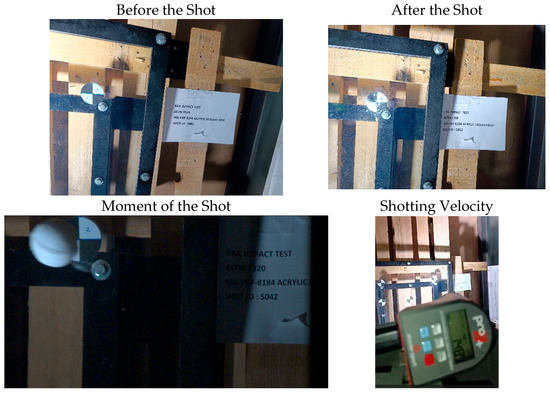
Figure 15.
S42 Shooting Images.
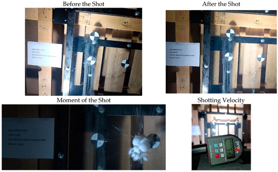
Figure 16.
S44 Shooting Images.
Another important point is that the artificial hailstones impacted the target point. After the impact tests, the canopies are shown in Figure 17. In this study, there was no need to utilize the Air Chrony speed measurement device, as identical values were obtained using both the slow-motion camera and the radar camera; therefore, a third validation was not required. Furthermore, the Digital Optical Micrometer, used to observe surface defects, showed no visible deformations or cracks. Consequently, despite the capability to measure dents on the canopy with a precision of 0.01 mm, no measurements were conducted due to the absence of any detectable dents.
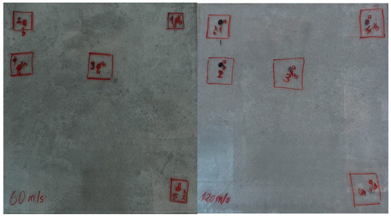
Figure 17.
Aircraft canopies after impact tests.
In Figure 17, nodes labeled as ‘a’ indicate the intended shot locations, and those labeled as ‘b’ represent the points where hits were achieved. As seen in Figure 18, there is a deviation between the targeted points and the points that were hit. This deviation is due to the airflow.
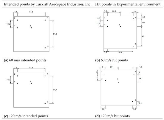
Figure 18.
Intended points and hit points.
A noticeable deviation exists between the targeted impact points and the actual points of impact. This deviation can be attributed to the effects of airflow, which influenced the trajectory of the hailstones. The airflow may have altered the expected path of the projectiles, leading to a disparity between the intended targets and the resultant impact locations.
6. Conclusions and Discussion
In accordance with the criteria established by ASTM standards, a comprehensive strength test was conducted on the canopy using specific impact points identified by Turkish Aerospace Industries, Inc. (TAI) and Volo Composites & Engineering. The testing involved subjecting the canopy to hail impacts, which were subsequently approved by the accreditation specified by TAI. The successful execution of this study is evidenced by the integration of the Volo-manufactured canopy hulk into the operations of two aircraft. The successful integration of the hail-resistant canopy manufactured by Volo into the operations of two aircraft demonstrates its practical applicability and reliability. Furthermore, the results indicate that the canopy is capable of withstanding hail impacts, confirming its suitability for use in large aircraft. Further, materials developed for aviation in various countries can significantly improve the effectiveness of hail impact tests, paving the way for improved aircraft safety standards. In this study, the aviation industry gains valuable insight into the durability and performance of canopies under hail impact conditions. In ongoing research by the first author, numerical analyses will significantly enhance the understanding of the impact phenomena. Future research should incorporate both experimental and numerical approaches to build a comprehensive understanding of hailstone impacts. The reliability and safety of aerospace components worldwide are greatly improved by US MIL requirements. By providing a strict framework for quality control, these standards enable global manufacturers to produce goods that meet uniform performance criteria. This commonality enhances safety and efficiency in the global aircraft industry by ensuring consistent quality and encouraging cross-border cooperation. Adhering to these guidelines improves production procedures and maintains industry-wide quality standards.
Author Contributions
Conceptualization, M.E.U.; methodology, G.Y.; validation, G.Y. and M.E.U.; formal analysis, M.E.U.; investigation, G.Y.; resources, G.Y.; data curation, G.Y.; writing—original draft preparation, M.E.U.; writing—review and editing, M.E.U.; visualization, M.E.U.; supervision, M.E.U.; project administration, M.E.U.; funding acquisition, M.E.U. All authors have read and agreed to the published version of the manuscript.
Funding
This study was financially supported by the Scientific Research Project at Aydin Adnan Menderes University (BAP: MF-24006 and MF-24009).
Data Availability Statement
The authors confirm that the data supporting the findings of this study are available within the article.
Acknowledgments
The authors would like to express our sincere gratitude to all those who contributed to this study. It is an honor to have conducted hail impact tests on the canopy developed by Volo Composites for the HURKUS 2 aircraft, designed by TAI. Authors extend our heartfelt thanks to both organizations for providing us with the opportunity to conduct this work and for the invaluable support that allowed us to achieve this milestone. Additionally, the corresponding author of this study would like to express his appreciation to Volo Composites for their generous scholarships awarded to his master’s and Ph.D. students, which has greatly supported their academic pursuits. We would also like to thank Deputy General Manager of Volo Composites Çiğdem Alkan and the engineers at TAI and Volo Composites for supplying the canopies used in the tests, ensuring the success of our experiments. Finally, our special thanks go to Mehmet Acar, Dilara Kop, Rumeysa Çıkaran and Mert Bas in our Faculty of Engineering for their invaluable assistance during the experimentation process.
Conflicts of Interest
The authors declare the following financial interests/personal relationships which may be considered as potential competing interests: Mehmet Eren Uz reports that the specimens (canopies) were provided by Volo Composite Solutions. Mehmet Eren Uz reports a relationship with Turkish Aerospace Industries Inc that includes non-financial support. If there are other authors, they declare that they have no known competing financial interests or personal relationships that could have appeared to influence the work reported in this paper.
References
- Leslie, L.; Leplastrier, M.; Buckley, B. Estimating future trends in severe hailstorms over the Sydney Basin: A climate modelling study. Atmos. Res. 2008, 87, 37–51. [Google Scholar] [CrossRef]
- Raupach, T.H.; Martius, O.; Allen, J.T.; Kunz, M.; Lasher-Trapp, S.; Mohr, S.; Rasmussen, K.L.; Trapp, R.J.; Zhang, Q. The effects of climate change on hailstorms. Nat. Rev. Earth Environ. 2021, 2, 213–226. [Google Scholar] [CrossRef]
- Singh, N.; The Airbus A320 was Flying from Mallorca to Vienna when It Encountered Severe Turbulence and Hail (mediadrumimages/@exithamster). Independent, 11 June 2024. Available online: https://edition.cnn.com/travel/austrian-airlines-hailstorm-damage-plane-nose (accessed on 1 September 2025).
- Niemeier, B.A.; Burley, C.E. Hailstone Response of Body Panels–Real and Simulated. SAE Tech. Pap. 1978, 780398, 1–12. [Google Scholar] [CrossRef]
- Johnson, T.E.; Schaffnit, W.O. Dent Resistance of Cold-Rolled Low-Carbon Steel Sheet. SAE Tech. Pap. 1973, 82, 1719–1730. [Google Scholar] [CrossRef]
- Nomura, S.; Yutori, Y.; Iwaya, J.; Miyahara, M.; Kokubo, I. A study of the dynamic dent resistance. In Proceedings of the Efficiency in Sheet Metal Forming, IDDRG 13 th Biennial Congress, Melbourne, Australia, 20–25 February 1984; pp. 394–402. [Google Scholar]
- Fleming, H.G.; Skarajew, M.; Szalla, J.A.G. A Laboratory Dent Test for Outer Panel Steels; SAE Technical Paper, Society of Automotive Engineers: Warrendale, PA, USA, 1997. [Google Scholar]
- Shi, M.F.; Brindza, J.; Michel, P.; Bucklin, P.; Belanger, P.; Prencipe, J. Static and Dynamic Dent Resistance Performance of Automotive Steel Body Panels. SAE Tech. Pap. 1997. [Google Scholar] [CrossRef]
- Flüeler, P.; Stucki, M.; Guastala, F.; Egli, T. Hail Impact Resistance of Building Materials Testing, Evaluation and Classification. In Proceedings of the 11 DBMC International Conference on Durability of Building Materials and Components Istanbul Technical University, Istanbul, Turkey, 11–14 May 2008. [Google Scholar]
- Schulson, E.M. The structure and mechanical behavior of ice. J. Miner. Met. Mater. Soc. (JOM) 1999, 51, 21–27. [Google Scholar] [CrossRef]
- Ramsay, H.; Liang, M. Experimental Investigation, Development and Optimization of Steel Roof Sheeting Against the Effect of Hail Impact. Bachelor’s Thesis, University of Wollongong, Wollongong, Australia, 2015. [Google Scholar]
- Swift, J.M. Simulated Hail Ice Mechanical Properties and Failure Mechanism at Quasi-Static Strain Rates. Ph.D. Bachelor’s Thesis, University of Washington, Seattle, WA, USA, 2013. [Google Scholar]
- Uz, M.E.; Yilmaz, G.; Bircan, T. The Making of a Hailstone Simulated Realistic Damage. J. Eng. Sci. Des. 2017, 5, 411–423. [Google Scholar] [CrossRef]
- Volo Composites & Engineering Ltd. Hürkuş-II Canopy Design and Manufacturing Project Hail Strike Test Plan; Volo Composites & Engineering Ltd.: Kahramankazan, Ankara, Turkiye, 2023; Rev. 16 July 2024. [Google Scholar]
- TBTEU-5210-FWS; Flight and Wing Structure Standard. Internal Technical Standard, Turkish Aerospace Industries (TAI): Ankara, Turkey, 2021.
- U.S. Department of Defense. MIL-PRF-8184F: Plastic, Poly (Methyl Methacrylate), Acrylic, Heat-Resistant; Naval Air Warfare Center Aircraft Division, U.S. Department of Defense: Lakehurst, NJ, USA, 1998.
- Bircan, T.; Uz, M.E.; Kirnak, H.; Erdem, E.; Goren, M.; Kop, M.D. Investigation of a Theory for Determining Hailstone Resistance. In Proceedings of the 13th International Congress on Advances in Civil Engineering, Izmir, Turkey, 12–14 September 2018. [Google Scholar]
- Uz, M.E.; Kop, M.D.; Yildirim, E.M. Analysis of Out-of-Plane Hail Impact Resistance of Steel Roof Panels. Exp. Tech. 2022, 46, 509–527. [Google Scholar] [CrossRef]
- Uz, M.E.; Kop, M.D.; Yildirim, E.M. Determining the empirical model for estimating the permanent deformation in flat roof panels under hail impact. AIP Adv. 2021, 11, 125117. [Google Scholar] [CrossRef]
- Uz, M.E.; Sızar, M.D. Analyzing Dent Resistance of Steel Roof Panels Subjected to Hail Impacts. J. Eng. Sci. Des. 2021, 9, 1015–1029. [Google Scholar] [CrossRef]
- Uz, M.E.; Teh, L.H.; Maguire, J. Developing Australia’s First Hail-Proof Roofing Profiles; Poster Presentation in SBRC; University of Wollongong: Wollongong, NSW, Australia, 2014. [Google Scholar]
- Yılmaz, G.; Uz, M.E.; Dawood, M.; Kop, M.D. Production of Artificial Hailstone with Liquid Nitrogen and Comparisons with Other Artificial Hailstones Up to Now. J. Eng. Sci. Des. 2020, 8, 1180–1189. [Google Scholar] [CrossRef]
- TAI (TUSAŞ–Türk Havacılık ve Uzay Sanayi A.Ş.). Company Profile. TUSAŞ, Kazan, Ankara, Türkiye. 1973. Available online: https://www.tusas.com (accessed on 1 September 2025).
- ASTM Standard F320-16; Standard Test Method for Hail Impact Resistance of Aerospace Transparent Enclosures. ASTM International: West Conshohocken, PA, USA, 2016. Available online: https://store.astm.org/f0320-21.html (accessed on 1 September 2025).
Disclaimer/Publisher’s Note: The statements, opinions and data contained in all publications are solely those of the individual author(s) and contributor(s) and not of MDPI and/or the editor(s). MDPI and/or the editor(s) disclaim responsibility for any injury to people or property resulting from any ideas, methods, instructions or products referred to in the content. |
© 2025 by the authors. Licensee MDPI, Basel, Switzerland. This article is an open access article distributed under the terms and conditions of the Creative Commons Attribution (CC BY) license (https://creativecommons.org/licenses/by/4.0/).