Abstract
This study examines the landing performance of a four-legged lunar lander equipped with magnetorheological dampers when landing on discrete lunar soil. To capture the complex interaction between the lander and the soil, a coupled dynamic model is developed that integrates flexible multibody dynamics (FMBD), granular material modeling, and a semi-active fuzzy control strategy. The flexible structures of the lander are described using the floating frame of reference, while the lunar soil behavior is simulated using the discrete element method (DEM). A fuzzy controller is designed to achieve the adaptive MR damping force under varying landing conditions. The FMBD and DEM modules are coupled through a serial staggered approach to ensure stable and accurate data exchange between the two systems. The proposed model is validated through a lander impact experiment, demonstrating good agreement with experimental results. Based on the validated model, the influence of discrete lunar regolith properties on MR damping performance is analyzed. The results show that the MR-based landing leg system can effectively absorb impact energy and adapt well to the uneven, granular lunar surface.
1. Introduction
Lunar exploration represents one of the most significant milestones in space science and engineering, offering unprecedented opportunities for advancing fundamental research, resource utilization, and deep space exploration. Over the past decades, a series of landmark missions have demonstrated the progress and challenges of achieving safe lunar landings, including the Surveyor [1], Apollo 11 [2], the Chang’e program [3], and the iSpace’s Resilience lander [4]. Among these, the legged-type landing system [5,6] has become a widely adopted configuration in lunar exploration missions due to its inherent advantages in absorbing impact energy, enhancing the stability of the lander. These systems are particularly well-suited to cope with the unpredictable and often rugged terrain of the lunar surface, where safe and stable landing conditions cannot be guaranteed.
In recent years, as landing technologies continue to evolve to meet the demands of future deep space exploration, there has been a growing interest in the integration of advanced damping mechanisms into legged landing systems. Among these, magnetorheological (MR) dampers [7,8] have emerged as a promising solution due to their adaptive and controllable damping characteristics, which enable real-time adjustment of landing response according to varying surface conditions [9,10]. The MR dampers are filled with magnetorheological fluid, whose viscosity changes rapidly under a magnetic field. Thus, its yield strength can be controlled by different magnetic field produced by the energized coils in the MR damper. Recently, Wang et al. [11] have demonstrated that the MR dampers can reduce the peak acceleration by 63.6% compared to traditional aluminum honeycomb dampers under the condition of maximum cabin acceleration.
Over the past few decades, extensive research has been conducted on modeling the MR damper landing system. Chio et al. [12] established the dynamic model for an MR landing gear system, and the feasibility and effectiveness of MR fluid-based landing gear systems are demonstrated. Han et al. [13] compared the landing efficiency of a two-core type of semi-active magnetorheological (MR) damper under two different controllers. Maeda et al. [9] proposed a semi-active control-based MR fluid lunar lander, and established a simplified 2D-dynamic model for the lander. Jo et al. [14] verified the performance and stability of an MR damper through numerical simulations and drop tests. Wang et al. [10] established the dynamic model for a new type of lunar lander equipped with magnetorheological fluid (MRF) buffers, and designed the semi-active control method. Zhu et al. [15] introduces a walkable cat-legged lander equipped with magnetorheological dampers. These studies primarily focus on the control strategies and dynamic modeling of magnetorheological landing systems, without thoroughly addressing the complex interactions between the landing system and the lunar surface. The lunar surface is covered with a layer of loose regolith, and the motion of the soil upon collision influences the landing response [16]. Thus, the energy dissipated by the soil must be factored into the model to obtain more accurate results.
Some empirical formulas are used to describe the complex contact forces between the lander and soil, such as the Bekker model [17] and Archimedean law [18]. Although these models are computationally efficient, they often suffer from limited accuracy and exhibit a strong dependence on empirically derived parameters. To reveal the deformation characteristics of soil, some researchers used the Mohr-Coulomb [19] and Drucker-Prager/Cap models [20] based on the finite element method. However, the finite element method models soil as an elasto-plastic material governed by specific failure criteria, thereby overlooking the discrete nature and physical properties of individual particles [21]. This limitation hinders its ability to accurately describe interparticle interactions and their impact on macroscopic soil behavior. Considering the discrete nature of lunar soil, the discrete element method (DEM) [22] is a potential modeling approach. DEM has shown good results in dealing with various engineering issues related to lunar soil, such as lunar soil drilling [23], driving on the moon [24], and landing on the moon [25]. Compared with the FEM, DEM can capture the large deformations and displacement phenomena in bulk materials [26]. However, DEM, by itself, cannot handle multibody systems like flexible brush samplers due to the absence of constraint joint formulations [25]. For applications involving the coupling of complex mechanical structures with granular systems, such as a lander landing on the discrete lunar soil, introducing multibody dynamics into the discrete element method is a promising alternative method [5,25,27].
For the scenario where an MR fluid-based landing leg system lands on the lunar surface, a further dynamic model considering multi-physics coupling is required. It can provide deeper insights into the impact of sand on landing performance for the semi-control lander. Therefore, this paper proposes an efficient FMBD-DEM coupling model. This model integrates flexible multibody and particle systems to simulate interactions between landing legs and lunar soil, and the fuzzy control module to regulate the damping force of the MR damper. The remainder of the paper is organized as follows: Section 2 introduces the modeling of the lander with the MR-damper landing system, followed by an introduction of the modeling for the lunar soil in Section 3. In Section 4, the detailed illustration for the coupling of the FMBD-DEM dynamic model is given. Then, in Section 5, an example is presented to verify the model’s effectiveness. In Section 6, the interaction between the MR-damper landing system and lunar soil is simulated. Finally, conclusions are summarized in Section 7.
2. Dynamic Modeling of the MR-Damper Lander
Figure 1 illustrates the structural schematic of a legged lander, which consist of the main lander body and four sets of landing leg. Each leg assembly comprises a primary damping strut, two auxiliary damping strut, and a footpad. In this paper, the cabin is recognized as a rigid body, and the struts are modeled using the Euler-Bernoulli beam. Additionally, the Kirchhoff thin plate is adopted to describe the footpad.
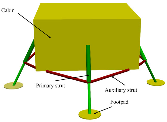
Figure 1.
The structure diagram of the lunar lander.
2.1. Rigid-Flexible Coupling Model for the Lunar Lander
2.1.1. Rigid Body Formulation
The motion of a rigid body can be described by Cartesian coordinates, and the generalized coordinates are expressed as follows:
where is the global position vector of the mass center of the rigid body. is the Euler quaternions, which satisfies the constraint equation .
The dynamic equation of rigid body i can be expressed as follows:
where is the generalized mass matrix, is the generalized external force, is the generalized inertia force of the rigid body , respectively.
By introducing the transformation matrix , the generalized mass matrix can be formulated as follows:
where represents the mass matrix of the rigid body , is the mass of body , is the identity matrix. is the moment of inertia matrix of the rigid body about its center of mass. The transformation matrix can be expressed as follows:
where .
2.1.2. Flexible Body Formulation
In the floating frame of reference formulation [28], a floating coordinate system on the flexible body is established, and the configuration of the body is treated as a superposition of the large rigid-body motion of the floating frame and the deformation relative to this frame. The deformation is represented as a combination of the body’s s-order mode shapes, each weighted by a corresponding coefficient, referred to as the modal coordinate of the body .
The deformation at node j on the flexible body can be written as follows [29]:
where is the translational modes of node j.
The position of node j can be expressed as follows:
where is the global position vector of the floating coordinate system, is the position vector of node j relative to the origin of the floating coordinate system under the undeformation configuration.
The global velocity and acceleration vector of node j can be formulated as follows:
where , , .
The dynamic equation in the form of velocity variation for the deformed body can be expressed as follows:
where represents external forces applied in node j. and are the strain array and stress array at node j, respectively. N represents the number of nodes of the deformable body.
Introducing the modal stiffness matrix and modal damping matrix of the deformable body, one can obtain
Thus, Equation (8) can be written as follows:
where the mass matrix , the inertia force , , the external force .
Similarly, the dynamic equation can be written as follows:
where represents the generalized coordinates matrix, is the generalized mass matrix, is the generalized external force matrix, represents the generalized elastic force matrix.
Introducing the transformation matrix as follows:
where , , , .
2.2. Modeling of Damper Force
In this study, a bypass magnetorheological fluid (MRF) buffering system is used for the primary struts, while the auxiliary struts employ aluminum honeycomb structures for energy absorption. Under external loading, the aluminum honeycomb collapses, thereby dissipating impact energy. By incorporating two-stage honeycomb elements, the auxiliary struts are capable of providing both tensile and compressive buffering. The mechanical model of this structure is not elaborated here and can be found in the relevant literature [10].
2.2.1. Damping Force of the Magnetorheological (MR) Damper
The bypass magnetorheological fluid (MRF) buffering damper is shown in Figure 2. The system comprises a bypass cylinder with an inner diameter of , A magnetic core characterized by a diameter of and a length of , and three sets of electromagnetic coils. Additionally, it includes a main cylinder (inner diameter ), a piston, a nitrogen compensation chamber, a piston rod with a diameter of , as well as two connecting cylinders with diameters and lengths , respectively. The annular clearance between the magnetic core and the bypass cylinder is denoted as d. In the course of impact, the viscosity of the magnetorheological fluid can be rapidly modulated by varying the applied magnetic field, enabling an adjustable damping force. The damper force consist of the air spring force , the non-adjustable damping force and the adjustable damping force .
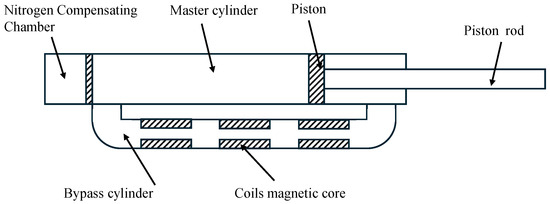
Figure 2.
The MR damper for the primary strut.
The air spring force can be expressed as follows:
where represents the diameter of the piston, represents the initial pressure of the air chamber, represents the chamber’s initial volume, and is the real-time volume of the air chamber.
The non-adjustable damping force of the shock absorber is given by [10]:
where represents the length of the coil-wound section in the middle of the magnetically conductive inner core, is the shear yield strength of the magnetorheological (MR) fluid, is the inner diameter of the bypass chamber, and represents the diameter of the gap between the magnetic core and the bypass cylinder.
The adjustable damping force of the shock absorber is given by [10]:
where represents the length of the bypass cylinder, d is the width of the gap between the magnetic core and the bypass cylinder, represents the viscosity of the MR fluid, , and , are the equivalent length and inner diameter of the connecting cylinders, respectively. and represent the length and inner diameter of the master cylinder, respectively. v is the cushioning velocity of the damper.
2.2.2. Design of the Fuzzy Controller for the Lander
The fuzzy control approach has emerged as an efficient and practical solution for controlling systems with nonlinearities, uncertainties, or incomplete models. The fuzzy controller can be pre-designed and computed offline, allowing for fast and reliable real-time implementation without the need for intensive online processing.
During the landing process, particular attention is paid to the impact overload response and landing stability. Therefore, in the controller design presented in this paper, emphasis is placed on the vehicle’s acceleration and attitude angles. According to the basic principles of fuzzy rule tables, when the error is positive and the rate of change of the error is also positive, it indicates a growing deviation that must be corrected quickly to suppress further increase; thus, a large negative control adjustment is applied. Conversely, if the error is positive but the rate of change is negative, the system shows a natural tendency to return to equilibrium, so a smaller control adjustment is sufficient.
Based on the above concept, the inputs of the fuzzy controller are selected as the vehicle’s acceleration a, the rate of change of acceleration , and the pitch and roll angles , . According to the literature, during the landing process, the maximum impact acceleration of the lander does not exceed 5 g, and its pitch and roll angles remain within 4°. Therefore, the range of and is set as degree. Additionally, the range of jerk is selected as . The control voltages , , , are selected as the output of the controller to adapt the damping force , , , , and their ranges are . Figure 3 gives the indices of the footpads. Four fuzzy sets are defined for acceleration a, namely Zero, Small, Medium, and Big, corresponding to the linguistic variables {Z, S, M, B}. For the jerk , two fuzzy sets are defined: Zero and Big, denoted as {Z, B}. For pitch angle and roll angle , three fuzzy sets are defined: Negative, Zero, and Positive, represented by the set {N, Z, P}. As for the voltage output U, seven fuzzy sets are introduced: Zero, Small, Small-Medium, Medium, Small-Big, Medium-Big, and Big, corresponding to the set {Z, S, SM, M, SB, MB, B}. Fuzzy inference is performed using the Mamdani method, and defuzzification is carried out using the centroid method. The relationships between the input and output variables are shown in Figure 4.
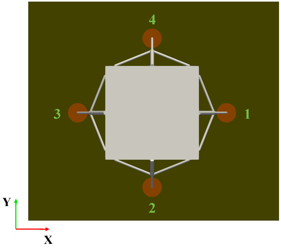
Figure 3.
The indices of the footpads.
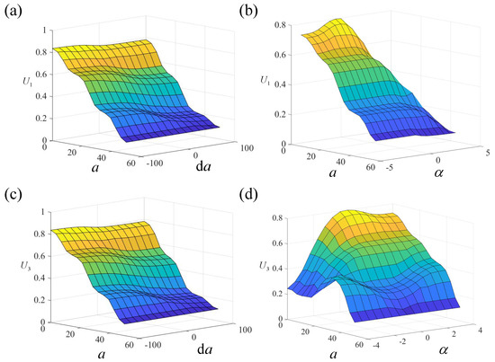
Figure 4.
The relationship between the output and input variables. (a) vs. a and . (b) vs. a and . (c) vs. a and . (d) vs. a and .
2.3. Dynamic Model of the Rigid-Flexible Coupling System
The dynamic equations of the constrained rigid-flexible coupling multibody system is a set of index-1 differential-algebraic equation as follows:
where is the generalized mass matrix of the system, represents the vector of generalized coordinates of the system, represents the constraint conditions of the system, is the constraint Jacobian matrix, is the vector of Lagrange multipliers, and is the right-hand side of the acceleration constraint equation.
Equation (16) can be solved by variable-step implicit algorithms, and the Moore-Penrose method [30] or the Baumgarte method [31] can be used to perform a constraint violation correction on the generalized positions and generalized velocities of the system.
3. Discrete Element Method
Considering the convenience of spherical particles in geometric representation and the efficiency in the contact detection, discrete element methods based on spherical particles have been widely applied in the numerical simulation of lunar regolith [5,24,25]. Additionally, to capture interlocking behavior of non-spherical particles, additional rolling friction resistance is often incorporated into the contact force between spherical particles [32].
3.1. Equations of Particles
Based on the Newton-Euler formulation, the governing equations for the motion of individual particles , where N is the total number of particles, are as follows:
here denotes the mass of particle i, and represents its moment of inertia about the center of mass. The is the global position coordinate vector of particle i, while is the angular velocity vector expressed in the inertial frame. The gravitational acceleration is given by . The relative position vector from the particle’s center of mass to the contact point is defined as , where is the position vector of contact point k on the particle i. The vector denotes the contact force vector at the contact point, and is the total number of contacts acting on the particle i. Furthermore, represents the rolling friction torque associated with the contact.
3.2. Hertz-Mindlin Contact Model
The contact force can be expressed as the sum of the normal and tangential contact force.
The normal contact force can be formulated as follows:
where represents the spring stiffness, is the damping coefficient, and is the unit normal vector pointing from the center of the particle i to the contact point. represents the normal relative velocity at the contact point.
For spherical particles, the normal overlap can be readily calculated by
here , denote the radii of particle i and j, respectively. A contact is considered to occur when .
The tangential contact force is computed based on the model proposed by Mindlin and Deresiewicz [33]. The form of friction can be determined by predicting the magnitude of the friction force, , expressed as follows [34]
where is the tangential stiffness, and is the tangential displacement vector. is the incremental tangential displacement and is formulated as , where is the time step. The frictional contact force can be obtained as follows [34]
where represents the tangential damping coefficient, and represents the coefficient of friction. The Hertzian contact force is defined as . When sliding occurs, the condition is satisfied, the tangential displacement vector must be updated as for next time step’s .
Rolling resistance is also taken into account, and the torque generated by the rolling friction is expressed as [35]
where represents the rolling friction coefficient, is the distance between the contact point and the mass center of particle i, is the relative angular velocity vector of the two particles.
4. Coupling Model for the Lander and Lunar Soil
The conventional serial staggered (CSS) approach is used to couple the flexible multibody system and the granular matter. This method allows the two solvers to independently integrate the equations of their respective systems using separate time steps. Due to its simple coupling structure and high computational efficiency, it has been widely applied in coupled simulations involving large-scale granular systems [36]. The implementation mainly consists of two components: (1) contact detection; and (2) a coupling data transfer scheme.
4.1. Contact Detection
4.1.1. Sphere-Beam Contact Detection
The diagram of sphere-beam contact detection is shown in Figure 5. Denoting the particle’s global position as , and its rotation matrix as . The two nodes of the beam are marked as and , respectively, and they can be expressed as follows:
where is origin coordinates of floating frame in the reference frame, is undeformed position vector of node j relative to floating frame, is element in mode coordinates .
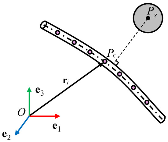
Figure 5.
The sphere-beam contact detection. ( represents the perpendicular line from point to the beam.)
The closet projection point on the beam centerline can be obtained as follows:
where .
The overlap can be expressed as
when , the contact between the sphere and beam occurs.
4.1.2. Sphere-Plate Contact Detection
The contact configuration between the sphere and triangle patch is shown in Figure 6. Denoting the particle’s global position as , and its rotation matrix as . Point , , are the nodes of the triangle patch, and their global position vector are , , , respectively.
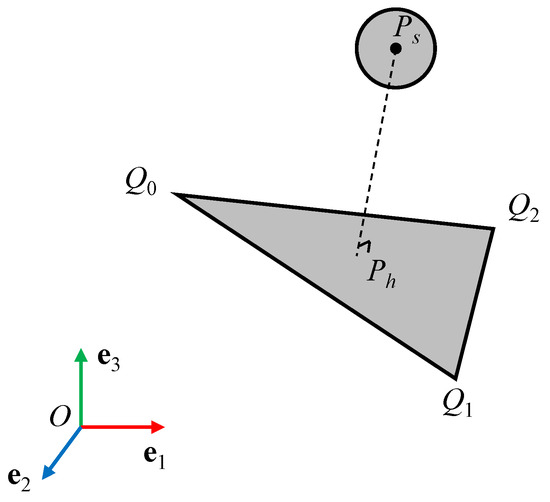
Figure 6.
The sphere-triangle contact detection. ( represents the perpendicular line from point to surface .)
The global position vector of the closet projection point
where and . The global position vector of node j under the deformed configuration can be expressed as follows:
where is origin coordinates of floating frame in the reference frame, is undeformed position vector of node j relative to the floating frame, is element in mode coordinates .
The condition of common normal line is as follows:
By solving Equation (29), one can obtain the values of . The potential contact interaction between the sphere and the triangular facet can be identified by evaluating the sign of , and the global position of the closest projection point P can be formulated as follows:
where in case of Point-to-edge contact, and satisfy the following relationship
The potential contact point on the sphere can be written as follows:
where is the radius of the particle.
The overlap between the sphere and the triangle patch is
when , contact occurs.
Similarly, based on the obtained contact information, the contact force can be calculated by Equations (19) and (22). Then, the generalized contact force applied to the flexible body j can be expressed as follows:
where represents the shape function of the element. The generalized contact force for the flexible multibody system can be obtained by assembling by its index in the generalized coordinates.
4.2. Coupling Model for the Semi-Control Lander and Lunar Soil
This paper adopts the conventional serial staggered (CSS) method within the framework of weak coupling to link the flexible multibody dynamics and the discrete element method. The diagram of the time integration method is shown in Figure 7.
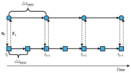
Figure 7.
Coupling diagram of FMBD-DEM. (The circles represent the time integration points of FMBD, and the squares represent the time integration points of the DEM).
In the coupled simulation, the discrete element method (DEM) solver begins to advance using time-step , proceeding through n steps to reach the synchronization point. Then, the multibody dynamics solver starts with the time-step . At the synchronization, the two solvers exchange displacement and contact force information. Specifically, the motion information of the flexible multibody system is transferred to the DEM solver as a boundary condition, while the contact forces computed by the DEM solver are fed back to the flexible multibody system.
Taking the two circles shown in Figure 7 as an example, the serial coupling procedure between the flexible multibody system and the discrete element method is detailed as follows:
Firstly, at time , the motion information of the flexible multibody system is transferred to the DEM solver as the moving boundaries. The DEM solver advances using time-step for n steps to time . At this moment, the equivalent generalized contact force that is applied to the multibody system is calculated as follows:
where represents the generalized contact force applied to the multibody system in time step.
Then, the flexible multibody dynamic solver starts to work using the time-step with the constant force . By introducing the coupling force , the dynamic equations of a flexible multibody system are rewritten as follows:
Finally, the simplified computational flowchart for the FMBD–DEM coupling model is shown in Figure 8.
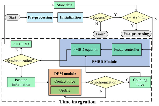
Figure 8.
The computational flowchart of the FMBD-DEM coupling model.
5. Validation
To verify the correctness of the FMBD-DEM coupling model, the landing process of the lunar lander from literature [37] is simulated within the proposed framework. The lander has an initial vertical impact velocity of −6.2 m/s and a total mass of 3000 kg. A schematic of the lander’s structure is shown in Figure 9. The lunar regolith is modeled using spherical particles with a radius of 2 cm. The material properties assigned to these particles are listed in Table 1.
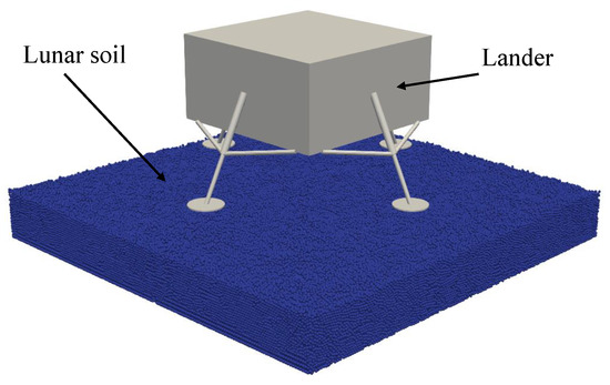
Figure 9.
The schematic of a lander landing on the lunar soil.

Table 1.
The simulation parameter of landing process.
The result comparison between simulation and experiment is listed in Table 2. It can be seen that the results obtained from the proposed coupled model are in good agreement with the experimental data, with a relative error within 10%, demonstrating favorable accuracy. Moreover, since the EDEM software does not support multibody system modeling, it is incapable of simulating the buffering behavior of the lander. As a result, it overestimates both the soil penetration depth and the peak impact force during the landing process. Furthermore, the results are also consistent with those reported in the referenced coupled model. Compared to the model in the literature, the approach adopted in this study employs the floating frame of reference formulation for modeling small-deformation flexible bodies, offering improved computational efficiency.

Table 2.
Comparison of results.
6. Simulation and Analysis for MR-Damper Lander-Lunar Soil Interaction
6.1. Coupling Simulation of an MR-Damper Lunar Impacting Lunar Soil
Based on DEM, the lunar soil is described using the collection of spherical particles, and the parameters for DEM are listed in Table 1. Table 3 presents the simulation parameters of the lander, which are sourced from the literature [10]. To improve computational efficiency, this study concentrates on the initial impact phase, therefore, the simulation time is limited to 1.0 s.

Table 3.
The simulation parameter of the lander.
Figure 10 illustrates the contours which show the state of the interaction between the lander and the lunar soil at different moments, in which different colors indicate the magnitude velocity of the particles. It can be clearly observed that at s, the lander’s footpad interacts with the lunar soil particles, transferring part of the landing energy to the granular medium and resulting in a sharp change in particle velocities. Subsequently, collisions and friction between particles lead to the gradual transfer and dissipation of kinetic energy. As a result, the disturbed region expands over time, while particle velocities decrease, as shown in Figure 10.
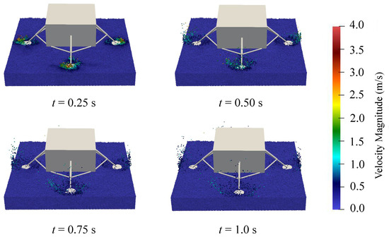
Figure 10.
The state of interaction between the lander and lunar soil.
The dynamic characteristics of the lunar lander when landing on the lunar soil are shown in Figure 11. Figure 11a presents the time history of lander acceleration during the landing process. It can be observed that, due to the presence of the magnetorheological (MR) damping system, the lander’s acceleration is actively regulated, resulting in oscillations. The peak acceleration is within the allowable design range. Figure 11b shows the variation of the lander’s velocity over time. Under the effect of the damping system, the velocity gradually decreases to zero, indicating a successful and stable landing. The lander’s descent height is depicted in Figure 11c, with a maximum value of 0.35 m. Figure 11d illustrates the variation of the lander’s mechanical energy throughout the landing process.
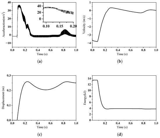
Figure 11.
The dynamic characteristics of the lunar lander: (a) Acceleration of the lander vs. time. (b) Velocity of the lander vs. time. (c) Descent distance of the lander vs. time. (d) Mechanical energy of the lander vs. time.
To evaluate the influence of lunar surface discreteness on the performance of the MR landing system, a comparative simulation study is conducted between landings on a discrete lunar surface and a non-discrete (continuous) one. Here, the non-discrete surface is modeled using a rigid plane. Figure 12 gives the comparisons between these two landing conditions. As shown in Figure 12a, when the discreteness of the lunar regolith is considered, the peak impact acceleration of the lander is reduced. Moreover, due to the friction, flowing, and rearrangement of particles during the landing process, coupled with the control effect of the magnetorheological damper, the variation of the lander’s acceleration becomes more pronounced. Figure 12b presents a comparison of the lander’s mechanical energy variation under the two landing scenarios. It can be observed that particle flow and friction dissipate a portion of the energy in the form of heat, accounting for approximately 6.5% of the total mechanical energy.
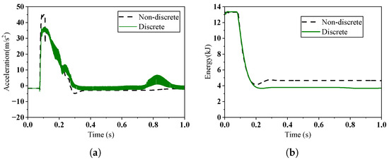
Figure 12.
The dynamic characteristics of the landing system using discrete and non-discrete lunar soil: (a) Comparison of the lander’s acceleration. (b) Comparison of the lander’s mechanical energy.
6.2. Parameter Analysis
In this section, the effects of various landing parameters on the dynamic response of the landing process are analyzed. Specifically, the landing attitude, landing velocity, and friction coefficient are selected as key parameters. Additionally, the landing performance is assessed by focusing on the impact acceleration, velocity, and mechanical energy of the lander.
6.2.1. Landing Performance Under Different Attitudes
In this section, three typical landing attitudes are selected for simulation based on the different contact sequences between the lander’s legs and the ground. These include simultaneous four-leg landing, 1-2-1 sequential landing, and 2-2 sequential landing conditions. The simulation results are shown in Figure 13. Figure 13a shows the impact acceleration curves of different landing configurations. As shown in Figure 13a, under the four-leg landing condition, the acceleration curve has only one peak. Under the 1-2-1 landing condition, the acceleration exhibits three peaks, and under the 2-2 landing condition, the acceleration shows two peaks. These correspond to the different contact scenarios between the lander’s legs and the ground. Due to the adjustable function of the magnetorheological damper, it can be observed that the maximum impact acceleration of the lander remains nearly constant across different landing configurations. Figure 13b shows a comparison of the lander’s velocity curves. It can be seen that under the four-leg landing condition, a greater buffering force is provided, resulting in a faster change in the velocity curve for this landing configuration. In terms of energy consumption, it can be observed that the differences among the three landing configurations are minimal, as shown in Figure 13c.

Figure 13.
The dynamic characteristics of the landing system under different landing attitudes: (a) Comparison of the lander’s acceleration. (b) Comparison of the lander’s velocity. (c) Comparison of the lander’s mechanical energy.
6.2.2. Landing Performance Under Different Friction Coefficients
The landing performance under different friction coefficients between the footpads and lunar soil is investigated in this section. Three sets of simulations are performed with friction coefficients of 0.2, 0.3, and 0.5, and the results are compared in Figure 14. As shown in Figure 14a, with the increase in the friction coefficient, the peak acceleration of the lander slightly increases. This is because a higher friction coefficient imposes more restriction on the cushioning process. Comparing the velocity curves in Figure 14b, it can be observed that the higher friction coefficient also limits the rebound of the lander. Figure 14c illustrates the comparison of the lander’s mechanical energy, which indicates that the difference in energy consumption under different friction coefficients is negligible.

Figure 14.
The dynamic characteristics of the landing system under different friction coefficients: (a) Comparison of the lander’s acceleration. (b) Comparison of the lander’s velocity. (c) Comparison of the lander’s mechanical energy.
6.2.3. Landing Performance Under Different Velocities
Three simulations are conducted with impact velocities = 3.0 m/s, 3.8 m/s, and 5.0 m/s to investigate the effect of velocity on landing performance, and the simulation results are shown in Figure 15. It can be observed in Figure 15a that with an increase in impact velocity, the peak acceleration of the lander also increases. However, with the adjustment of the magnetorheological (MR) damper, the difference in peak acceleration between = 3.0 m/s and = 3.8 m/s is minimal. When the impact velocity reaches 5 m/s, the lander experiences a sharp peak in acceleration. Yet, under the MR damping control, this peak is significantly reduced. Figure 15b presents a comparison of the lander’s mechanical energy at different impact velocities. It can be observed that as the landing velocity increases, the remaining mechanical energy of the lander decreases. This is because a higher impact velocity triggers more intense particle flow, causing the particles to absorb more of the impact energy.
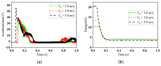
Figure 15.
The dynamic characteristics of the landing system under different velocities: (a) Comparison of the lander’s acceleration. (b) Comparison of the lander’s mechanical energy.
7. Conclusions
This study proposes an FMBD-DEM coupling framework to simulate the interaction between an MR-damper landing leg system and lunar soil. The framework integrates a flexible multibody system, granular matter, and a fuzzy controller. A serial staggered algorithm is proposed to couple the FMBD and DEM solvers. The model’s accuracy is validated against full-scale terrestrial landing experiments. Simulations show that the discrete nature of lunar soil absorbs about 6.5% of the lander’s mechanical energy, reducing peak acceleration compared to non-discrete surfaces. The MR-damper landing system demonstrates robust adaptability, maintaining consistent overload performance across varying conditions.
Future research will focus on the simulation of non-spherical regolith particles to better capture the realistic morphology and mechanical behavior of lunar soil. In addition, comparative studies between continuum mechanics and discrete element methods can be conducted to clarify their respective advantages and limitations in modeling the lander–soil interaction, which will help establish clearer guidelines for selecting appropriate modeling approaches under different landing scenarios and improve the accuracy of predicting lunar landing dynamics.
Author Contributions
Conceptualization, H.L. and B.L.; methodology, H.L.; software, H.L. and B.L.; validation, B.L.; formal analysis, H.L.; investigation, H.L.; data curation, B.L.; writing—original draft preparation, H.L.; visualization, H.L.; supervision, B.L. and W.Y.; project administration, B.L. and W.Y.; funding acquisition, B.L. and W.Y. All authors have read and agreed to the published version of the manuscript.
Funding
This research was supported by the National Natural Science Foundation of China (No. 12502042, 52235003), for which the authors are grateful. This research was supported by the Postdoctoral Fellowship Program of CPSF under Grant Number GZC20252752 and Jiangsu Funding Program for Excellent Postdoctoral Talent.
Data Availability Statement
Data will be made available on request.
Conflicts of Interest
The authors declare no conflicts of interest.
References
- Godwin, R. Surveyor: Lunar Exploration Program; Apogee Books: Burlington, ON, Canada, 2006. [Google Scholar]
- Bennett, F.V. Apollo Experience Report: Mission Planning for Lunar Module Descent and Ascent; Technical report; NASA Lyndon B. Johnson Space Center: Houston, TX, USA, 1972. [Google Scholar]
- Ye, P.; Sun, Z.; Zhang, H.; Li, F. An overview of the mission and technical characteristics of Change’4 Lunar Probe. Sci. China Technol. Sci. 2017, 60, 658–667. [Google Scholar] [CrossRef]
- ispace. ispace Announces Series 3 Lander Achieves Significant Testing Milestone for Mission 4. 2025. Available online: https://ispace-inc.com/news-en/?p=7963 (accessed on 2 October 2025).
- Ji, S.; Liang, S. DEM-FEM-MBD coupling analysis of landing process of lunar lander considering landing mode and buffering mechanism. Adv. Space Res. 2021, 68, 1627–1643. [Google Scholar] [CrossRef]
- Wei, X.; Lin, Q.; Nie, H.; Zhang, M.; Ren, J. Investigation on soft-landing dynamics of four-legged lunar lander. Acta Astronaut. 2014, 101, 55–66. [Google Scholar] [CrossRef]
- Ahure’, L.; Wereley, N.M. Behavior of Magnetorheological Fluids Employing Carrier Fluids Certified for Landing Gear Use. In Proceedings of the Smart Materials, Adaptive Structures and Intelligent Systems, Ellicott City, MD, USA, 28–30 October 2008; Volume 43314, pp. 849–857. [Google Scholar]
- Lee, J.; Oh, K. Hybrid Damping Mode MR Damper: Development and Experimental Validation with Semi-Active Control. Machines 2025, 13, 435. [Google Scholar] [CrossRef]
- Maeda, T.; Otsuki, M.; Hashimoto, T.; Hara, S. Attitude Stabilization for Lunar and Planetary Lander with Variable Damper. J. Guid. Control Dyn. 2016, 39, 1790–1804. [Google Scholar] [CrossRef]
- Wang, C.; Nie, H.; Chen, J.; Lee, H.P. The design and dynamic analysis of a lunar lander with semi-active control. Acta Astronaut. 2019, 157, 145–156. [Google Scholar] [CrossRef]
- Wang, C.; Chen, J.; Li, X.; Chen, H.; Nie, H.; Lin, F. Design, dynamic analysis, and experiments of MRF dampers for lunar landers. Adv. Space Res. 2021, 68, 3012–3025. [Google Scholar] [CrossRef]
- Choi, Y.T.; Wereley, N.M. Vibration Control of a Landing Gear System Featuring Electrorheological/Magnetorheological Fluids. J. Aircr. 2003, 40, 432–439. [Google Scholar] [CrossRef]
- Han, C.; Kang, B.H.; Choi, S.B.; Tak, J.M.; Hwang, J.H. Control of Landing Efficiency of an Aircraft Landing Gear System with Magnetorheological Dampers. J. Aircr. 2019, 56, 1980–1986. [Google Scholar] [CrossRef]
- Jo, B.H.; Jang, D.S.; Hwang, J.H.; Choi, Y.H. Experimental Validation for the Performance of MR Damper Aircraft Landing Gear. Aerospace 2021, 8, 272. [Google Scholar] [CrossRef]
- Zhu, J.; Ma, J.; Chen, J.; Wang, C.; Li, Y.; Fan, Z.; Lu, C. Improving landing stability and terrain adaptability in Lunar exploration with biomimetic lander design and control. Acta Astronaut. 2025, 226, 860–875. [Google Scholar] [CrossRef]
- Cao, P.; Hou, X.; Wang, Y.; Li, M.; Rao, X.; Shi, Y. Flexible airbag cushioning for Martian landing based on discrete element method. Adv. Space Res. 2019, 63, 2566–2583. [Google Scholar] [CrossRef]
- Yue, S.; Nie, H.; Zhang, M.; Huang, M.; Xu, D. Optimization and Performance Analysis of Oleo-Honeycomb Damper Used in Vertical Landing Reusable Launch Vehicle. J. Aerosp. Eng. 2018, 31, 04018002. [Google Scholar] [CrossRef]
- Shi, T.; Yang, Y.; Zhang, Z.; Liu, C.; Liu, C.; Ma, D. Soft-landing dynamics of a type of four-legged space lander. Aerosp. Sci. Technol. 2024, 150, 109217. [Google Scholar] [CrossRef]
- Pucker, T. Numerical study on modeling the soil footpad interaction of lunar soft landers at touchdown. Comput. Geotech. 2024, 171, 106341. [Google Scholar] [CrossRef]
- Liang, D.; Chai, H.; Chen, T. Landing dynamic analysis for landing leg of lunar lander using Abaqus/Explicit. In Proceedings of the 2011 International Conference on Electronic and Mechanical Engineering and Information Technology, Harbin, China, 12–14 August 2011; Volume 8, pp. 4364–4367. [Google Scholar]
- Zhang, K.; Zhang, Y.; Wu, J.; Shi, J. Three-dimensional MFBD-DEM coupling simulation of flexible wire mesh wheel–soil over lunar rough terrain. Comput. Part. Mech. 2024, 12, 1349–1370. [Google Scholar] [CrossRef]
- Cundall, P.; Strack, O. A discrete numerical model for granular assemblies. Geotechnique 1979, 29, 47–65. [Google Scholar] [CrossRef]
- Liu, T.; Zhou, J.; Liang, L.; Zhao, Y.; Cao, D. A novel torque analysis method for drilling deep lunar soil by DEM. J. Terramech. 2021, 94, 23–37. [Google Scholar] [CrossRef]
- Zhu, J.; Zou, M.; Shen, Y.; Cao, H.; Chen, Z.; Qi, Y. 3D DEM-FEM simulation of the flexible metal wheel–soil interaction in low gravity environments. Proc. Inst. Mech. Eng. Part C J. Mech. Eng. Sci. 2023, 237, 1267–1278. [Google Scholar] [CrossRef]
- Lei, B.; Xu, H.; Tang, L.; Liu, J.; Liu, C. Modeling and analysis for landing airbag–lunar soil interaction using a CPU–GPU-based FMBD-DEM computational framework. Mech. Mach. Theory 2024, 198, 105668. [Google Scholar] [CrossRef]
- Coetzee, C. Review: Calibration of the discrete element method. Powder Technol. 2017, 310, 104–142. [Google Scholar] [CrossRef]
- Lei, B.; Xu, H.; Sun, Q.; Zhang, N.; Zhao, Z.; Liu, J. A CPU parallelized coupling framework for constrained flexible multibody system and granular matter based on contact-graph. Powder Technol. 2023, 430, 118973. [Google Scholar] [CrossRef]
- Likins, P.W. Modal method for analysis of free rotations of spacecraft. AIAA J. 1967, 5, 1304–1308. [Google Scholar] [CrossRef]
- Hong, J. Computational Dynamics of Multibody Sustem; Higher Education Press: Beijing, China, 1999. (In Chinese) [Google Scholar]
- Arabyan, A.; Wu, F. An improved formulation for constrained mechanical systems. Multibody Syst. Dyn. 1998, 2, 49–69. [Google Scholar] [CrossRef]
- Baumgarte, J.W. A New Method of Stabilization for Holonomic Constraints. J. Appl. Mech. 1983, 50, 869–870. [Google Scholar] [CrossRef]
- Jiang, M.; Yu, H.S.; Harris, D. A novel discrete model for granular material incorporating rolling resistance. Comput. Geotech. 2005, 32, 340–357. [Google Scholar] [CrossRef]
- Mindlin, R.D.; Deresiewicz, H. Elastic Spheres in Contact Under Varying Oblique Forces. J. Appl. Mech. 2021, 20, 327–344. [Google Scholar] [CrossRef]
- Rojek, J. Contact Modeling in the Discrete Element Method. In Contact Modeling for Solids and Particles; Springer International Publishing: Cham, Switzerland, 2018; pp. 177–228. [Google Scholar]
- Zhou, Y.; Wright, B.; Yang, R.; Xu, B.; Yu, A. Rolling friction in the dynamic simulation of sandpile formation. Phys. A Stat. Mech. Its Appl. 1999, 269, 536–553. [Google Scholar] [CrossRef]
- Shen, Y.; Liu, C.; Zhou, D.; Wang, Z.; Zhou, L.; Ma, H.; Zhao, Y. A parallel coupling framework for DEM-MBD: Model verification and application. Powder Technol. 2024, 448, 120257. [Google Scholar] [CrossRef]
- Xuyan, H.; Pingping, X.; Wang, Y.; Cao, P.; Tang, T. Theoretical and discrete element simulation studies of aircraft landing impact. J. Braz. Soc. Mech. Sci. Eng. 2018, 40, 115. [Google Scholar] [CrossRef]
Disclaimer/Publisher’s Note: The statements, opinions and data contained in all publications are solely those of the individual author(s) and contributor(s) and not of MDPI and/or the editor(s). MDPI and/or the editor(s) disclaim responsibility for any injury to people or property resulting from any ideas, methods, instructions or products referred to in the content. |
© 2025 by the authors. Licensee MDPI, Basel, Switzerland. This article is an open access article distributed under the terms and conditions of the Creative Commons Attribution (CC BY) license (https://creativecommons.org/licenses/by/4.0/).