Article

Nose Landing Gear Shimmy Analysis with Variable System Stiffness Under Time-Varying Load

1
State Key Laboratory of Precision Manufacturing for Extreme Service Performance, Central South University, Changsha 410083, China
2
AVIC Aircraft Landing Gear Co., Ltd., Changsha 410200, China
*
Author to whom correspondence should be addressed.
Aerospace 2025, 12(10), 926; https://doi.org/10.3390/aerospace12100926 (registering DOI)
Submission received: 10 September 2025 / Revised: 8 October 2025 / Accepted: 13 October 2025 / Published: 14 October 2025
(This article belongs to the Special Issue Advances in Landing Systems Engineering)

Abstract

Vertical load fluctuations alter nose landing gear (NLG) system stiffness and complicate shimmy dynamics. Based on the full-scale NLG static stiffness test data, the relationship between shock absorber stroke and system stiffness was fitted, and a nonlinear shimmy model considering time-varying loads was established. The numerical solution was achieved using the established Simscape model. The research results show that, under constant load conditions, considering the nonlinear growth characteristic of NLG system stiffness with shock absorber stroke, the lateral shimmy amplitude of the NLG is significantly reduced, while the rotational shimmy amplitude increases slightly; among these, lateral stiffness plays a dominant role in influencing shimmy stability. In addition, time-varying loads aggravate shimmy through two paths: first, the fluctuation of load amplitude directly changes the force state; second, vertical movement causes changes in the shock absorber stroke, which in turn leads to dynamic adjustment of system stiffness. This is of great help in guiding the stiffness design of the NLG system and accurately evaluating shimmy stability.

1. Introduction

The NLG is a key component used to support aircraft mass and absorb impact energy during ground parking, take-off, landing, and taxiing, and its service process is often accompanied by shimmy [1,2]. Shimmy is a serious vibration of NLG, which seriously affects the stability of the body and the operation of the aircraft. The shimmy damping device for the NLG of mainstream large aircraft is integrated into the steering actuator cylinder. During the normal takeoff and landing state, the system is in the operational mode, where the steering actuator cylinder does not provide shimmy damping. The factors influencing NLG shimmy include linear factors [3,4] and nonlinear factors [5,6,7]. With the development of flexible and large-scale aircraft, there exists strong coupling among various factors, which makes the dynamic behavior of the system very complex and makes it very difficult to analyze the shimmy mechanism [8,9].
The current literature on shimmy modeling focuses on the lateral and rotational degrees of freedom (DoF) [10,11], often assuming that the vertical motion of the aircraft is not taken into account; therefore, the influence factors of shimmy coupled with vertical motion will also be ignored. Thota et al. [12] used the method of nonlinear dynamics to evaluate the contribution of the three modes to different types of shimmy. The results show that the rotational mode and lateral modes are very strong, and the selection of appropriate global rotational damping is very important to reduce the velocity range of rotational shimmy. In recent years, Wang et al. designed a torsional nonlinear energy sink (NES) and established a nonlinear model of the dual-wheel nose landing gear, incorporating structural nonlinearities. They optimized the NES parameters to reduce the torsional shimmy area and decrease the amplitude [13,14]. Ruan et al. studied the influence of clearances under the manipulation state, defined multiple types of clearances, and found that axial clearance causes constant-amplitude vibration, while return clearance requires increased anti-shimmy damping [15,16]. Rahmani et al. suggest that the influence of longitudinal DoF on shimmy stability is negligible. They also constructed a model that considers vertical DoF [17,18] but did not quantify its coupling effect with system stiffness, resulting in an inability to explain shimmy deterioration under load fluctuations. The vertical load is a key parameter in the study of shimmy. In specific working conditions, the vertical load is regarded as a fixed value [19,20]. However, in the actual take-off, landing, and taxiing processes, the vertical load of the NLG will fluctuate dynamically, which will be more obvious in the case of strong wind or uneven road surface [21,22]. In the statistical load data report of a medium aircraft [23], the fluctuation coefficient of the vertical load can reach 0.5, which is enough to show the phenomenon of vertical load fluctuation.
The stiffness value of the system is a key parameter in the design phase of the NLG, which is affected by material properties, structural geometry, and the spatial position of the components. The general shimmy research law of the NLG shows that the higher the stiffness of the system, the better the anti-shimmy performance of the NLG [10,12,24]. Increasing the stiffness of the system will often increase the weight of the NLG system, but the product is evaluated based on multiple criteria. In recent years, the lightweight design of aircraft has attracted the attention of the majority of scholars [25,26,27,28]. Therefore, the stiffness of the NLG system cannot be increased blindly to improve the anti-shimmy ability, but it needs to be evaluated more accurately. Under the condition of meeting the anti-shimmy requirements, reducing the system stiffness and contributing to the lightweight design of the NLG system are valuable for the next generation of NLG design.
After NLG is put into use, material properties and structural geometry have been determined, and the stiffness of the system is only affected by the relative spatial position of the components, and the vertical DoF has a great influence on it. The impact energy can be dissipated by the NLG because the landing gear is designed with a shock absorber to accommodate vertical DoF, which includes multiple buffer forces [29]. The stroke of the shock absorber varies with the vertical load. With the development of numerical simulation modeling method [30,31,32], the detail establishment of NLG in shimmy model can be realized. It can promote the further study of the influence mechanism of shimmy. In experimental studies on shimmy, most focus on shimmy effect tests or dynamic verification tests [33,34]. Mustashin et al. [35] designed and manufactured a new type of small test system for the NLG, which aims to simulate the take-off and landing conditions of the NLG in the laboratory environment. There are few experimental studies on the stiffness of the NLG system. One of the important contributions of this paper is that, through full-scale NLG static stiffness tests, it quantifies, for the first time, the nonlinear relationship between shock absorber stroke and lateral/torsional stiffness, thus addressing the deficiency in existing models regarding the assumption of constant stiffness parameters.
To address the gaps in existing research and clarify the research direction, this study first proposes two core hypotheses to verify: (1) the lateral and torsional stiffness of the NLG system show nonlinear growth with the increase in shock absorber stroke, and this stiffness variation will significantly affect shimmy stability; (2) time-varying loads aggravate NLG shimmy through two paths—direct force state change caused by load amplitude fluctuation and dynamic stiffness adjustment caused by shock absorber stroke variation—and the coupling effect of the two paths needs to be quantified.
In this paper, a nonlinear shimmy mechanical model considering the time-varying system stiffness is proposed for the nose landing gear of a large aircraft. The coupling effect between shock absorber stroke and system stiffness is revealed, which provides a strategy for accurately evaluating the stiffness design of NLG system. The remaining sections of the paper are arranged as follows: Section 2 introduces the NLG shimmy model; Section 3 establishes the time-varying system stiffness model; Section 4 analyzes the influence of the system stiffness change on the shimmy stability under three working conditions; and Section 5 summarizes the whole paper.

2. NLG Shimmy Model

2.1. Physical Model

Figure 1 is a three-dimensional physical model of the NLG product of a large aircraft developed by our company, comprising constituent elements such as the outer cylinder, turning sleeve, piston, wheel, etc.
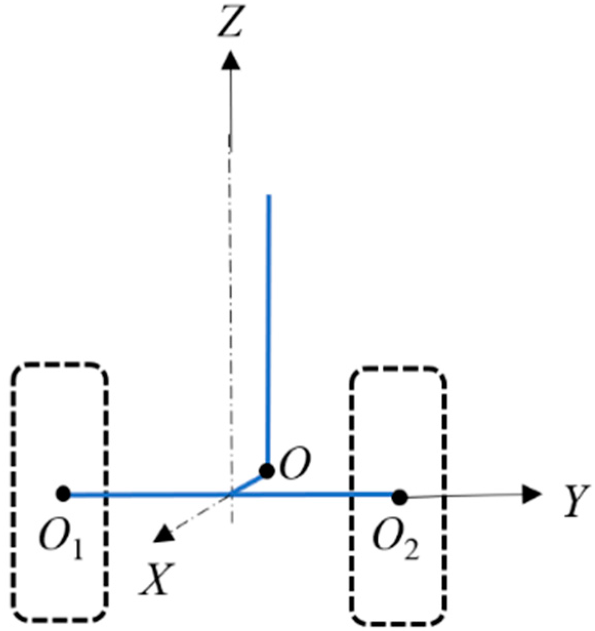
The NLG embodies a multifaceted dynamic system, which is simplified with reference to the work of Thota [11] and Rahmani [17], as shown in Figure 2. The axle is connected to the strut with a mechanical trail of e, and there is a pair of wheels with a radius of R at both ends of the axle. The rake angle φ designates the angular deviation between the strut plane and the vertical plane. The coordinate system of the landing gear is established with the X-axis aligned opposite the aircraft’s taxiing direction, as described in the Figure 2.
At the design phase, the stiffness of the NLG system is mainly affected by the appearance, shape, and material of each structure; during the service period, the system stiffness of the NLG is the compound stiffness of each component, which is affected by the relative spatial position of each component. For example, under different shock absorber stroke, the stiffness of the NLG system is quite different.

2.2. Mathematical Model

2.2.1. Dynamic Equations of Rotational and Lateral DoF

The main equation forms of rotational and lateral dynamics of NLG [11,19] are as follows:
I ψ ψ ¨ + M K ψ + M D ψ + M K α L + M K α R + M D λ L + M D λ R + 2 I δ ˙ V R + F K λ L + F K λ R e e f f F z L sin ϕ e e f f sin θ + D 2 cos θ + l g sin δ F z R sin ϕ e e f f sin θ D 2 cos θ l g sin δ = 0 .
I δ δ ¨ + M K δ + M D δ + M λ δ L + M λ δ R 2 I ψ ˙ V R F z L e e f f sin θ + D 2 cos θ + l g sin δ F z R e e f f sin θ D 2 cos θ l g sin δ = 0 .
Equation (1) presides over the rotational dynamics, while Equation (2) governs the lateral dynamics. ψ is the strut torsional angle, δ is the NLG lateral shimmy angle, lg is the nose landing gear height. Here, I ψ ψ ¨ , M K ψ , and M D ψ denote the inertia, stiffness, and damping terms associated with the torsional behavior of the strut, respectively. Similarly, I δ δ ¨ , M K δ , and M D δ represent the inertia, stiffness, and damping terms pertaining to the lateral motion of the strut. M K α L / R signifies the self-aligning moment exerted by the tire, M D λ L / R signifies the damping torque affecting tire rotation, and F K λ L / R denotes the lateral restoring force. Additionally, 2 I δ ˙ V R and 2 I ψ ˙ V R correspond to the gyroscopic moments influencing rotational and lateral DoF, respectively. eeff designates the effective stabilizing distance, which is defined as the perpendicular distance from the line of action of the tire lateral force to the shock absorber axis, where eeff = lg sin(δ) + e. The wheel swing angle θ is influenced by the forward inclination angle of the strut, θ = ψ cos(ϕ). Furthermore, the maximum lateral stroke is δ* = lg sin(δ).

2.2.2. Mechanical Equilibrium of Vertical DoF

The expression of NLG’s vertical DOF mechanical equation is as follows:
F z cos ( ϕ )     F a     F d     F i n e r t i a   =   0
F z k v d t = 0
where Fa, Fd, kv, and dt are air spring force, oil damping force, tire vertical stiffness, and tire vertical deformation, respectively. The vertical motion of the NLG is dominated by the piston’s axial movement (coupled with tire vertical deformation). Let meff denote the effective vertical mass of the NLG (including the mass of the piston, torque links, axle, and a portion of the aircraft mass transmitted to the NLG, meff = 1200 kg, as calibrated by full-scale test data), and l g ¨ denote the second derivative of the NLG height lg with respect to time (i.e., vertical acceleration of the NLG). The vertical inertia force is then F i n e r t i a =   m eff  ·   l g ¨ .
The vertical movement of the NLG will cause the shock absorber stroke to change, and the vertical deformation of the tire will also change due to vertical load. The change in NLG height can be expressed by the following formula:
l g   =   l g 0     S     d t
where l g 0 is the full extended length of the NLG and S is the shock absorber stroke.
It should be noted that the shock absorber stroke will lead to the change in NLG system stiffness, including lateral stiffness and torsional stiffness, and then couple with the lateral and rotational DoF. Therefore, the change in landing gear system stiffness caused by shock absorber stroke must be taken into account when modeling the NLG shimmy dynamics.

2.2.3. Tire Kinematics

The tire dynamics used in this paper is based on string theory [36] and has been applied by many scholars [37,38]. This paper adopts the tire dynamics equation of dual-wheel aircraft NLG proposed by Thota et al. [11]. This equation encapsulates the nonlinear kinematic interplay between the tire’s torsion angle ψ, lateral angle δ, and lateral deformation λ.
λ ˙ L + V σ λ L V sin θ l g δ ˙ cos δ e e f f h cos θ ψ ˙ cos ϕ D 2 ψ ˙ sin θ cos ϕ = 0
λ ˙ R + V σ λ R V sin θ l g δ ˙ cos δ e e f f h cos θ ψ ˙ cos ϕ + D 2 ψ ˙ sin θ cos ϕ = 0

2.2.4. Expression of Each Force Term

The stiffness and damping moment of the NLG are given by the following formula:
M K ψ   =   k ψ ψ
M K δ = k δ δ
M D ψ = c ψ ψ ˙
M D δ = c δ δ ˙
where kψ, kδ, cψ, and cδ are the torsional stiffness, lateral stiffness, torsional damping, and lateral damping of the strut, respectively.
The tire deformation produces moment M K α L / R . Within the tire’s slip angle limit αm, this self-aligning moment follows the sine law in relation to the slip angle α L / R ; beyond this limit, the self-aligning moment is zero [10].
M K α L / R = k α α m π sin α L / R π α m F z L / R   i f   α L / R α m 0                                                                                   i f     α L / R > α m  
The self-aligning moment coefficient is denoted as kα. Additionally, a moment term stemming from tire damping is expressed as follows along with the torque term stemming from tire damping:
M D λ L   =   M D λ R   =   c λ ψ ˙ cos ϕ V
where cλ stands for the tire damping coefficient. The lateral restoring force is modeled as follows [10]:
F K λ L / R   =   k λ tan 1 7.0 tan α L / R cos 0.95 tan 1 7.0 tan α L / R F y L / R
where kλ is restoration force coefficients, and the slip angles αL and αR of each tire are related to the corresponding tire deformations λL and λR by
α L / R = tan 1 λ L / R L
where L represents the tire relaxation length. The effective trail can be expressed as
e e f f = e cos ϕ + R + e sin ϕ tan ϕ
The vertical load Fz applied on the NLG can be divided into two components FzL and FzR:
F z L / R   =   F z 2 1 k v D F z sin γ   +   δ
In which γ = ψ sin(ϕ). The rotational vibration and lateral vibration of the NLG strut are interrelated through the lateral force exerted by the tire. The resultant torque arises from the force attributed to the lateral deformation of the tire.
M λ δ L / R = l g F K λ L / R cos θ cos ϕ

2.2.5. Oleo-Pneumatic Shock Absorber

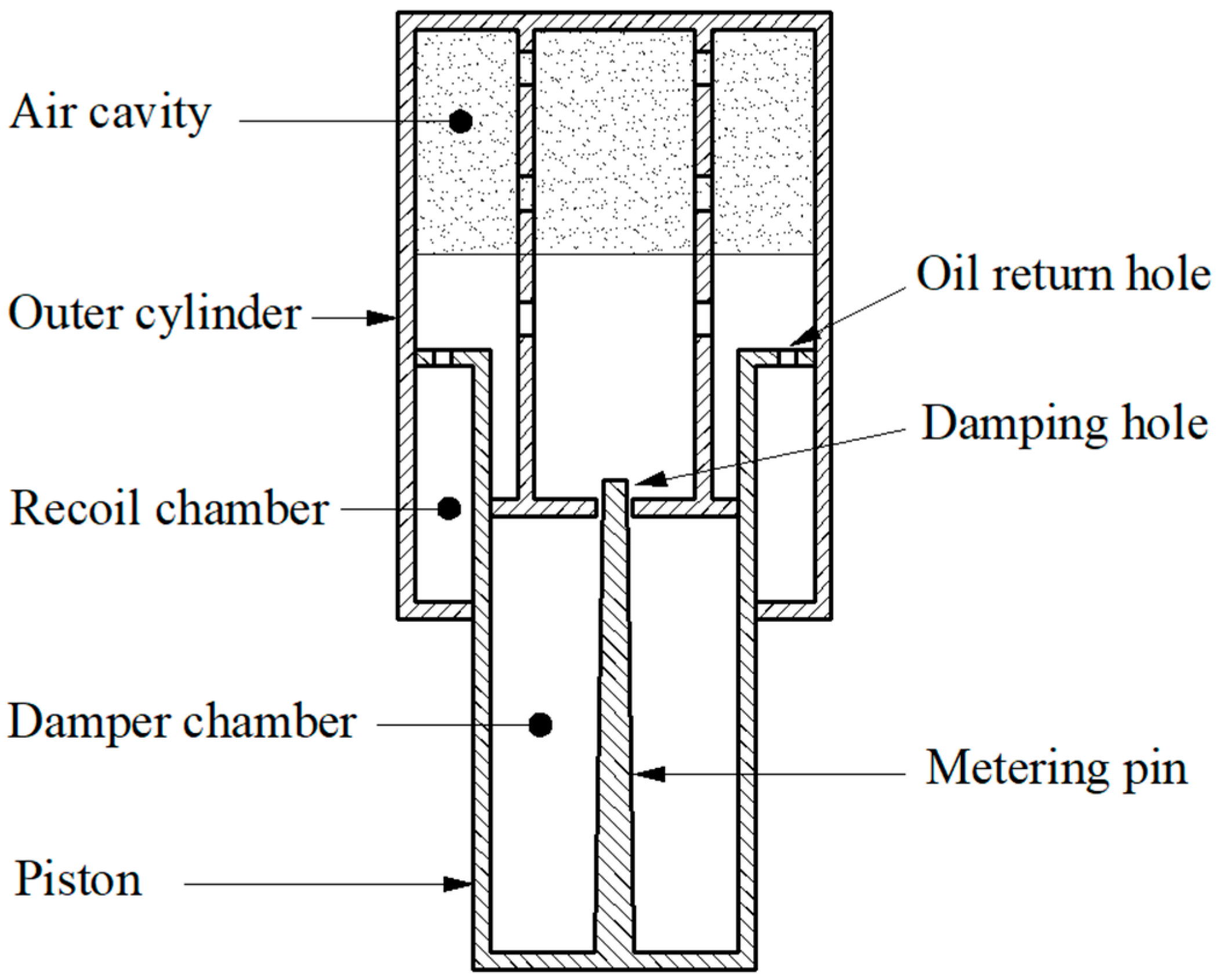
Based on the previous work of shimmy model, the mechanical model of shock absorber with vertical DoF is established in this paper. The structure of the oleo-pneumatic shock absorber of the landing gear is depicted in Figure 3, which mainly acts as a buffer in the process of landing and taxiing. Shimmy modeling involves air spring force and oil damping force. These two factors are strongly coupled with F z through the vertical dynamic balance equation, which are the core equations for transmitting time-varying load effects and obtaining S(t).
In accordance with Khapane’s proposition [39], the air spring force is defined as
F a = P a 0 V 0 V 0 A a S n P a t m A a
where Pa0 denotes the initial gas pressure, V0 signifies the initial gas volume, Patm represents the atmospheric pressure, Aa is the pressure area, n represents the air variability index, and S stands for the shock absorber stroke. The expression for the oil damping force is given by
F d = d S ˙ 2 s i g n ( S ˙ )
where S ˙ denotes the stroke rate of absorber stroke, and d represents the damping coefficient, which is modeled as a piecewise linear function, as illustrated in Figure 4.

2.2.6. MATLAB/Simulink Model Verification

The dynamic model for NLG shimmy, as outlined earlier, is simulated using the MATLAB/Simulink 2020b platform for numerical resolution. Table 1 provides a comprehensive listing of NLG parameters. Among these parameters, the structural parameters and tire parameters are referenced from Reference [10], while the shock absorber parameters are derived from the parameters of a certain type of NLG developed by our company. Comparing and analyzing the research results obtained by Thota et al. [10,11] based on bifurcation theory, as shown in Figure 5, the shimmy amplitude calculated from the current model closely mirrors those reported in the literature. The maximum error in the rotational shimmy amplitude is 3.2%, and the lateral is 2.8%, which verifies the accuracy of the model. The approximately 3% deviation in the results is primarily attributed to two factors: first, the adoption of different solution algorithms in the two studies, and second, potential discrepancies in calculation accuracy arising from variations in numerical computation setups (e.g., iteration steps, precision thresholds) between the two models.

3. Time-Varying System Stiffness Modeling

Based on the NLG shimmy model established in Section 2, this chapter reveals the correlation between the shock absorber stroke and system stiffness through full-scale tests, laying a foundation for the subsequent shimmy analysis under time-varying loads.

3.1. Full-Scale Static Stiffness Test of NLG

The position of the acting point of the force in the NLG full-scale static stiffness test is shown in Figure 6, where the points O1 and O2 are the center of the left and right wheels, and the point O is the intersection of the piston axis and the wheel axis plane.
The lateral stiffness of the NLG is the ratio of the lateral load to the lateral rotation angle, and the torsional stiffness of the landing gear is the ratio of the rotational load to the rotational angle. The expression is as follows:
Lateral stiffness k δ :
k δ   =   M S δ   =   P Y H arcsin ( Δ y H )
where MS is the moment in the Y-direction applied to the end of the relative strut and the action point is point O1 and O2 at the center of the wheel; δ is the total lateral rotation angle of the end of the strut; PY is the total load in the Y-direction applied at the point O1 and O2 at the center of the wheel; H is the vertical distance from the center of the wheel to the end of the strut; and Δy is the Y deformation of point O.
Torsional stiffness k ψ :
k ψ   =   M T θ   =   P X D arcsin ( 2 Δ x D )
where MT is the Z-direction torque applied at the wheel center points O1 and O2, θ is the torsion angle, PX is the X-direction load applied at the wheel center points O1 and O2, D is the distance between the wheel center points O1 and O2, and Δx is the X-direction deformation of points O1 and O2.
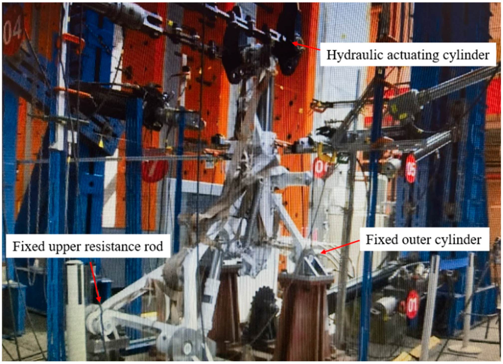
According to the NLG of a specific airliner, the full-scale NLG stiffness test is conducted. As shown in Figure 7, the NLG is inverted, the outer cylinder and the upper resistance rod are fixed, and the load is applied by the hydraulic actuator cylinder at the axle. The stroke of the shock absorber is adjusted by evacuating the gas inside the oil-pneumatic shock absorber and filling it with different amounts of oil. The load is applied by adding the appropriate preload and gradually increasing it to 100%, and is released after holding the pressure for 30 s. The lateral stiffness and torsional stiffness of the NLG are tested under the condition that the piston of the shock absorber is fully extended and the stroke of the piston is 0.107 m, 0.215 m, 0.322 m, and 0.43 m, and each stroke condition was repeated three times to take the average value to ensure data reliability.

3.2. Relationship Between Shock Absorber Stroke and NLG Stiffness

Due to the difference between the structural parameters of the NLG of a specific passenger aircraft and the numerical values studied in this paper, the stiffness test results are treated proportionally to match the numerical values. The curve of the relationship between NLG stiffness and shock absorber stroke is obtained as shown in Figure 8.
As shown in Figure 8, both lateral stiffness and torsional stiffness increase nonlinearly with stroke. The lateral stiffness is fitted with a quadratic polynomial (R2 = 0.9999), as test data indicate that the rate of its nonlinear growth with stroke exhibits quadratic curve characteristics; the torsional stiffness is fitted with a cubic polynomial (R2 = 0.9998) to capture the decreasing trend of its growth rate. Specifically, in the fully compressed state, the values of lateral stiffness and torsional stiffness are 3.59 times and 1.87 times those in the fully extended state, respectively. The relationships between lateral stiffness, torsional stiffness, and shock absorber stroke are as follows:
k δ   =   16,557,548 S 2   +   6,647,982 S   +   2,306,416
k ψ = 2,673,768 S 3 2,927,895 S 2 + 1,192,161 S + 210,949

3.3. Stroke Variation in Shock Absorber with Time-Varying Load

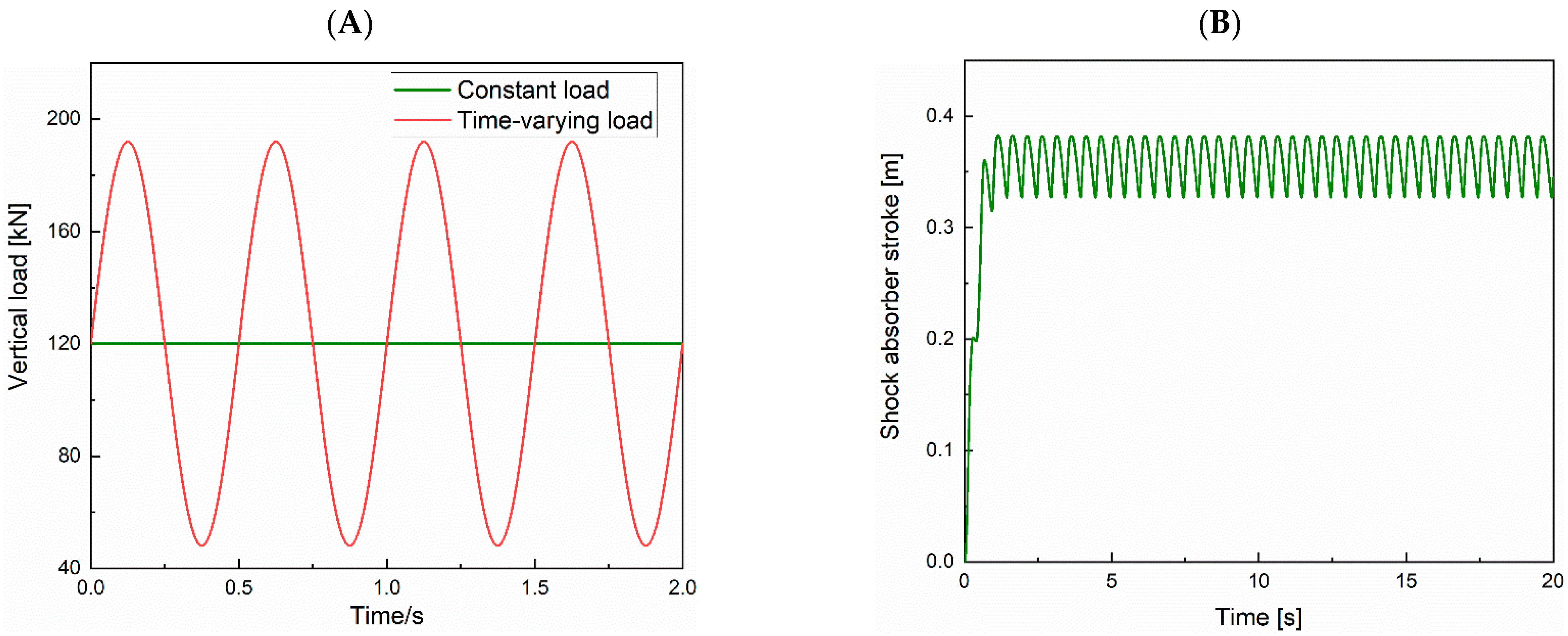
In prior analyses of shimmy dynamics, several researchers have employed a fixed value for vertical load and used amplified fixed values for the vertical load [40,41,42]. Nevertheless, given the trend towards larger and more flexible aircraft designs, especially during take-off and landing scenarios, on uneven terrains, and in crosswind conditions, it is crucial to acknowledge that the vertical load experiences fluctuations. Data gathered from the operational history of MD-82-83 aircraft during commercial service [23] indicate an incremental vertical load factor n of approximately 0.5, underscoring the noticeable variation in landing gear vertical loads. Building on previous research conducted by the present author [43], this study incorporates the n of the NLG in the form of a sine wave, yielding the simplified representation of time-varying load as follows. This approach enables an examination of the fundamental patterns governing the impact of time-varying load on shimmy. However, for subsequent endeavors, it is imperative to analyze dynamic response data for the entire aircraft’s vertical load.
Fz = Fz0 + nFz0sin(2πft)
where Fz0 and f are initial vertical load and vertical load frequency, respectively.
The values of n and f in Equation (25) are determined based on measured aviation engineering data and industry standards to ensure consistency with real NLG operating conditions.
n = 0.6: This coefficient is derived from conservative correction of the measured data. References [20,21] show that the measured load fluctuation coefficient (ratio of fluctuation amplitude to initial load) is 0.3–0.5 (maximum 0.48) under disturbed conditions (e.g., bumpy runways, crosswinds). Following the general aviation engineering practice of “load conservative coefficient” (measured maximum × 1.2), n = 0.6 is selected to cover over 95% of actual disturbed scenarios while avoiding model distortion from over-conservatism.
f = 2 Hz: This frequency is based on the ICAO Annex 14 Airport Runway Surface Roughness Standard, where the peak disturbance frequency of moderately rough runways (mainstream airport type) is 2 Hz. Moreover, this frequency is close to the natural frequency of the NLG’s vertical vibration (1.9–2.1 Hz, derived from the oleo-pneumatic shock absorber model in Section 2.2.5), enabling simulation of the critical “disturbance–resonance coupling” scenario that is most likely to exacerbate shimmy.
The resultant time-varying load curve is depicted in Figure 9A, while the corresponding shock absorber stroke is presented in Figure 9B. Combined with Formulas (19) and (20), the time-varying system stiffness can be obtained.

4. Analysis and Discussion

Based on the time-varying stiffness model constructed in the previous text, this section explores the mechanism by which stiffness variation and time-varying loads affect shimmy through dual-parameter and working condition comparison analyses.

4.1. Shimmy Analysis Considering the Change in System Stiffness

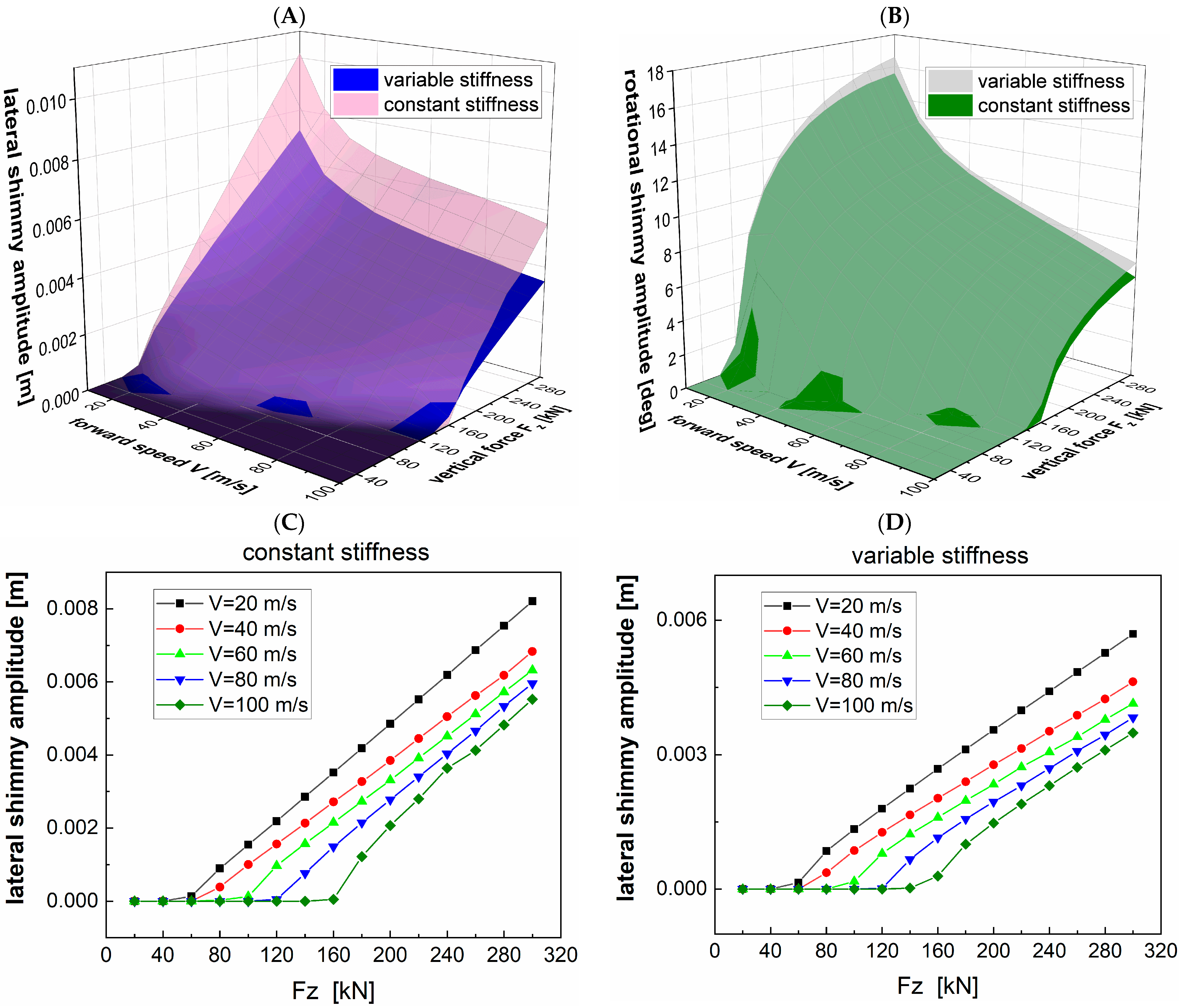
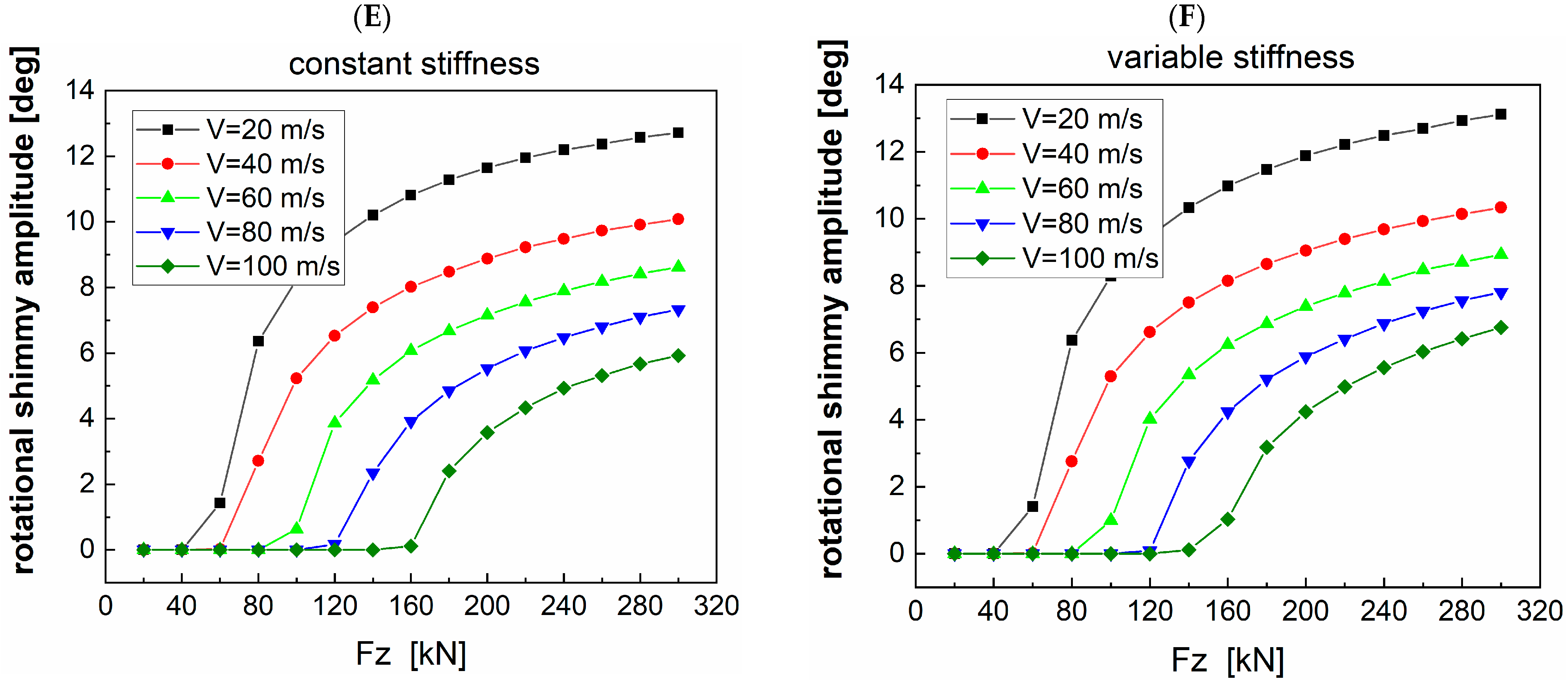
Employing the NLG shimmy model, the working conditions considering variable and constant system stiffness, respectively, are established. The investigation focuses on observing the alteration in shimmy amplitude with V and Fz as variables. Figure 10A,B provides 3D representations of shimmy amplitude, while (C) and (D) present the corresponding 2D curves for scenario (A), and (E) and (F) for scenario (B). Figure 10 reveals that, under constant stiffness conditions, the NLG system does not exhibit shimmy at low vertical loads. As vertical load increases, both lateral and rotational shimmy amplitudes gradually rise. Conversely, as taxiing speed increases, the shimmy amplitudes tend to decrease. Notably, the most pronounced shimmy occurs at the point (V, Fz) = (100, 300). When accounting for changes in system stiffness, the lateral shimmy amplitude experiences a reduction within the defined parameter range. The maximum amplitude decreases from 0.0102 m to 0.0072 m, as depicted on the blue surface in Figure 9A. Meanwhile, the rotational shimmy amplitude exhibits a slight increase due to the variations in system stiffness, with the maximum amplitude increasing from 15.58 deg to 16.59 deg, as depicted on the gray surface in Figure 10B. The results show that the increase in lateral rigidity enhances lateral constraints and reduces lateral amplitude; however, lateral forces are transmitted to the rotational degrees of freedom through mechanical trails, causing small amplification of rotational shimmy, reflecting the multi-degree-of-freedom coupling effect.
Notably, the improvement in anti-shimmy performance under stiffness variation is limited to lateral shimmy under constant load. This is because the nonlinear growth of lateral stiffness enhances the lateral constraint of the strut, directly suppressing lateral vibration; however, the increased lateral force is transmitted to the rotational DoF through the mechanical trail, leading to a slight increase in rotational shimmy amplitude. This indicates that the influence of stiffness variation on shimmy is coupled across DoF, and the performance improvement needs to be evaluated by distinguishing between shimmy types and load scenarios.

4.2. Influence of System Stiffness Change on Shimmy with Time-Varying Load

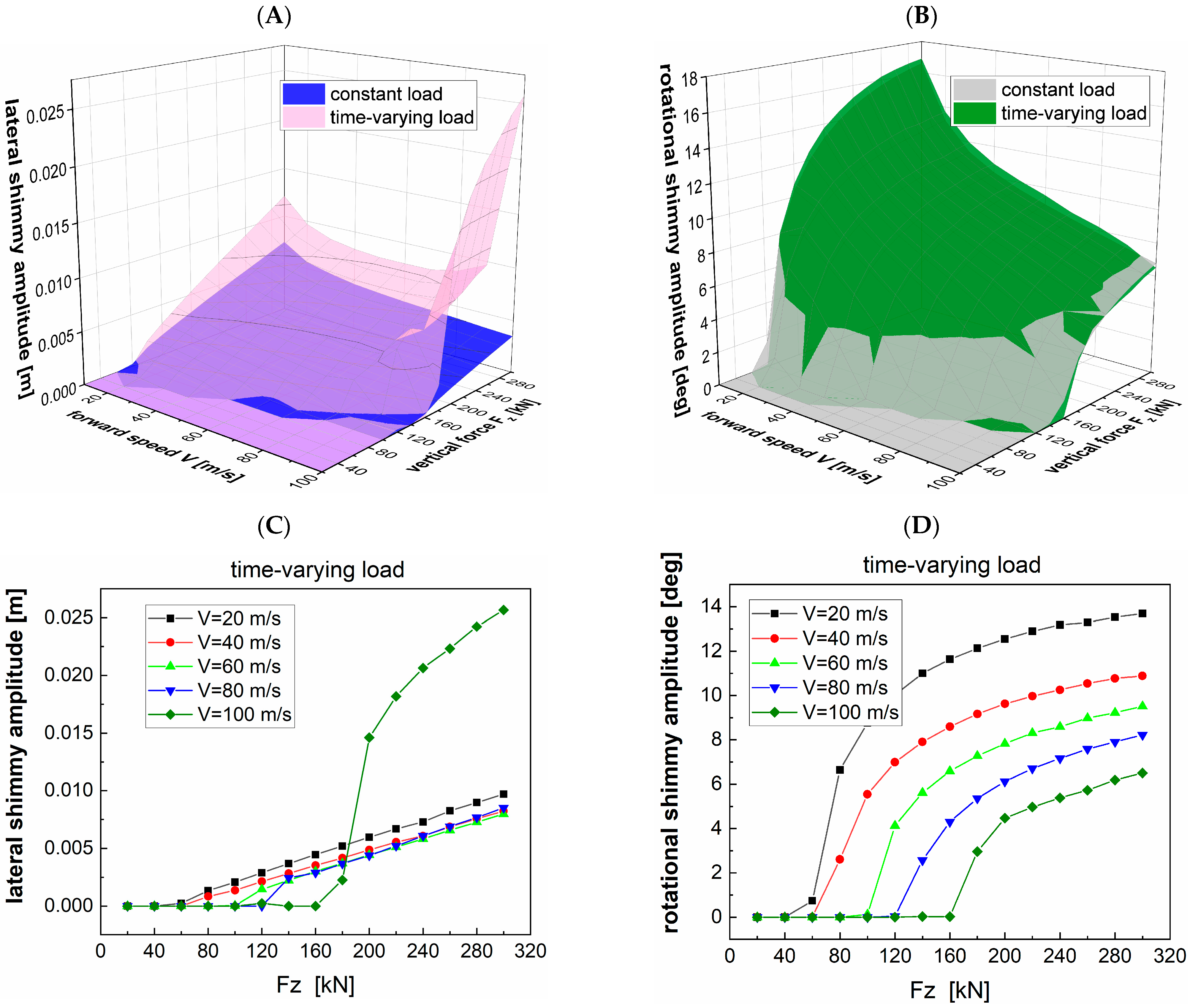
During the process of calculating the shimmy dynamic model that considers variable system stiffness, the time-varying load as depicted in Figure 9 is employed as the input. A comparative analysis is conducted between this scenario and the constant load condition to assess the combined effect of time-varying load and system stiffness on shimmy. Figure 11A,B presents 3D representations of shimmy amplitude, while Figure 11C,D provide the corresponding 2D curves for time-varying conditions, and the constant load conditions can be found in Figure 10D,F. Figure 11A demonstrates a significant increase in lateral shimmy amplitude within the designated shimmy zone under the influence of time-varying load. As taxiing speed V reaches 80 m/s, high-frequency fluctuations in stiffness induced by variable loads couple with the system’s resonant frequency, offsetting the damping suppression effect brought by the increase in speed, which leads to a rebound of amplitude that then increases rapidly. Notably, at the point (V, Fz) = (100,300), the amplitude of lateral shimmy surges from 0.00349 m to 0.02567 m. Moreover, the rotational shimmy amplitude exhibits a slight increase in the region of (V, Fz) ∈ (0~80, 160~300) by time-varying load, while experiencing a marginal reduction in other regions, as illustrated in Figure 11B. In summary, the time-varying load amplifies the NLG’s shimmy amplitude, consequently adversely affecting its taxiing stability.

4.3. Effect of Vertical Motion on Shimmy of NLG with Variable System Stiffness

The time-varying load will introduce the following changes to the shimmy model: Firstly, the Fz undergoes fluctuations, directly impacting Equations (1) and (2). Secondly, this variation in vertical load results in stroke alterations in the shock absorber, subsequently affecting system stiffness. While the combined effects of these factors have been scrutinized in Section 4.2, discerning the specific influence of system stiffness alterations induced by time-varying load on shimmy remains a challenge. To isolate these effects, we define a new operational condition termed vertical motion. The design purpose of the “vertical motion” working condition is to isolate the independent influence of the path “shock absorber stroke variation inducing system stiffness change” on shimmy, while eliminating the interference caused by vertical load fluctuation. Under this working condition, the vertical load Fz is strictly maintained constant (e.g., fixed at 200 kN in the subsequent analysis), and at the same time, the shock absorber is driven to perform vertical reciprocating motion to simulate the stroke variation trend of the shock absorber under time-varying loads.
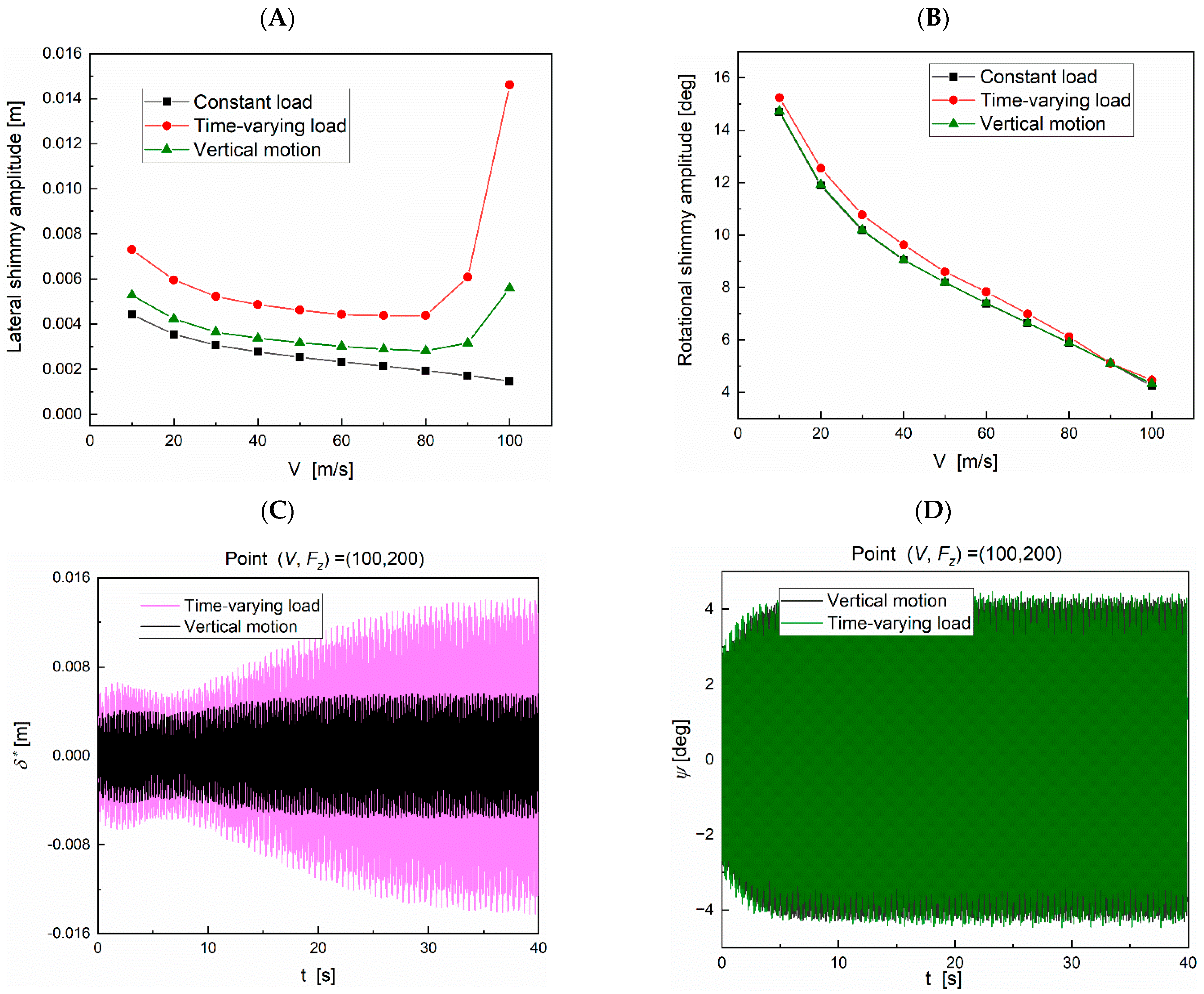
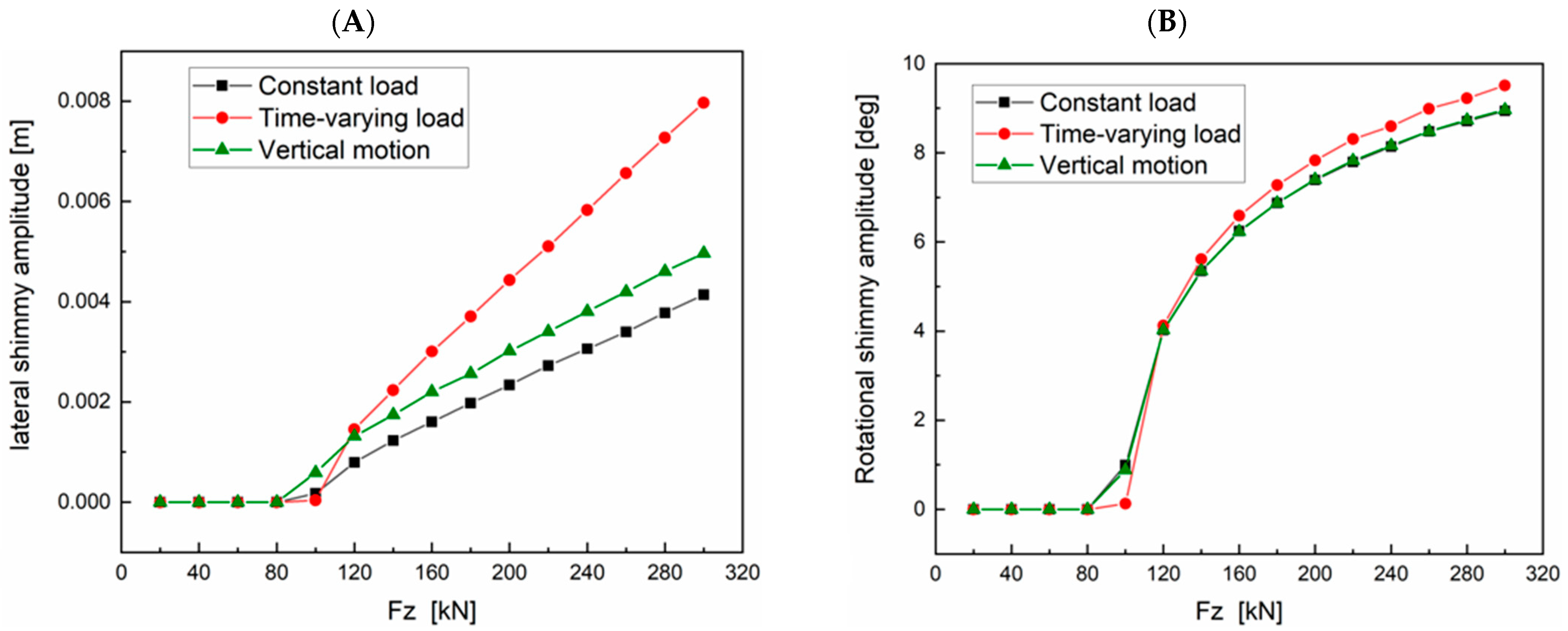
The three aforementioned shimmy models are subjected to comparative analysis. Fz = 200 kN is chosen to investigate the impact of vertical motion on shimmy across various speeds within the model accounting for system stiffness changes. The findings in Figure 12A demonstrate that, in terms of lateral shimmy amplitude, the effect of vertical motion is discernible under varying taxiing speeds. However, this influence is relatively smaller compared to that induced by time-varying load. This suggests that the influence of time-varying load on shimmy stems from both the Fz value and vertical motion. Regarding rotational shimmy amplitude, the impact of vertical motion can be considered negligible, as the stroke of the shock absorber exerts minimal influence on the torsional stiffness of the NLG system.
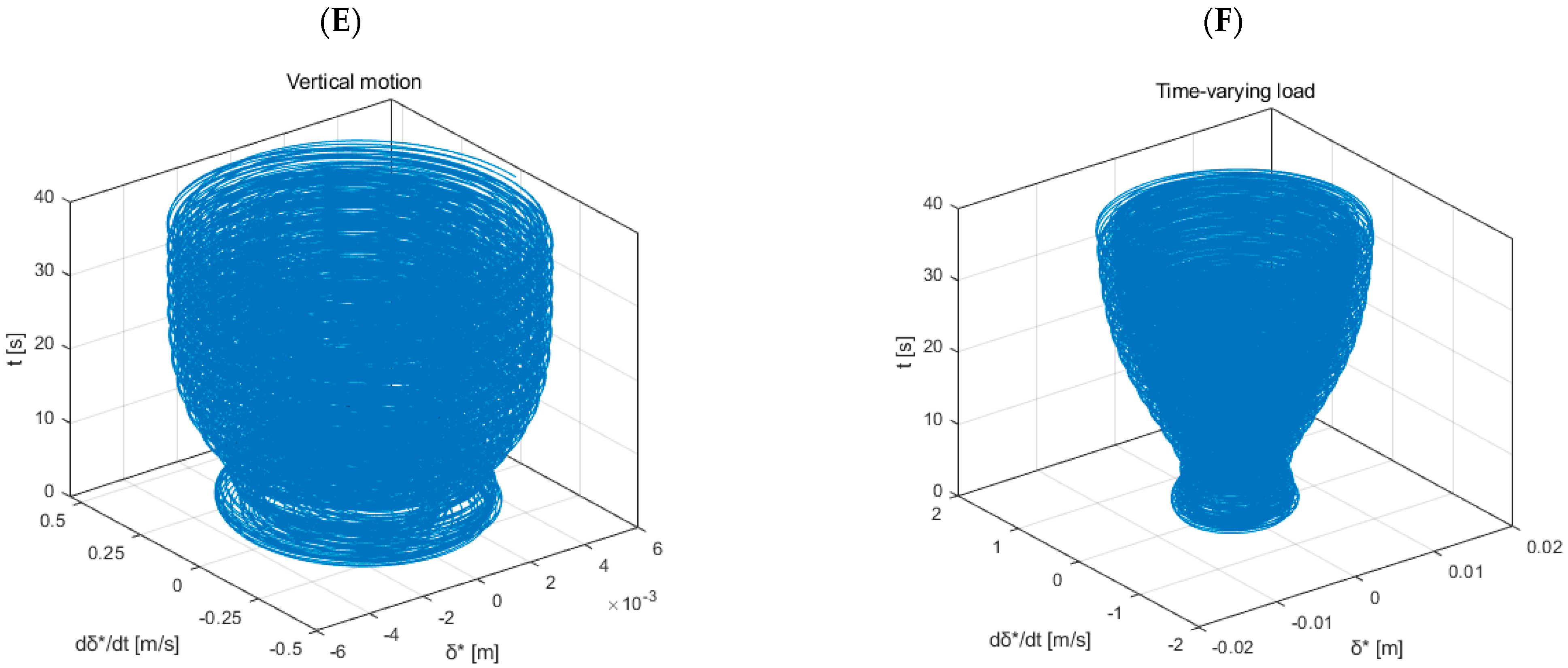
Taking the point (V, Fz) = (100, 200) as an example, a comparative analysis of the vibration curve and limit cycle of NLG shimmy is performed under the conditions of time-varying load and vertical motion. Under the above two conditions, the amplitudes of lateral shimmy and rotational shimmy fluctuate with time, as shown in Figure 12C,D. The corresponding phase diagram illustrates limit cycle oscillations, with the limit cycle under time-varying load conditions being more pronounced, as demonstrated in Figure 12E,F.
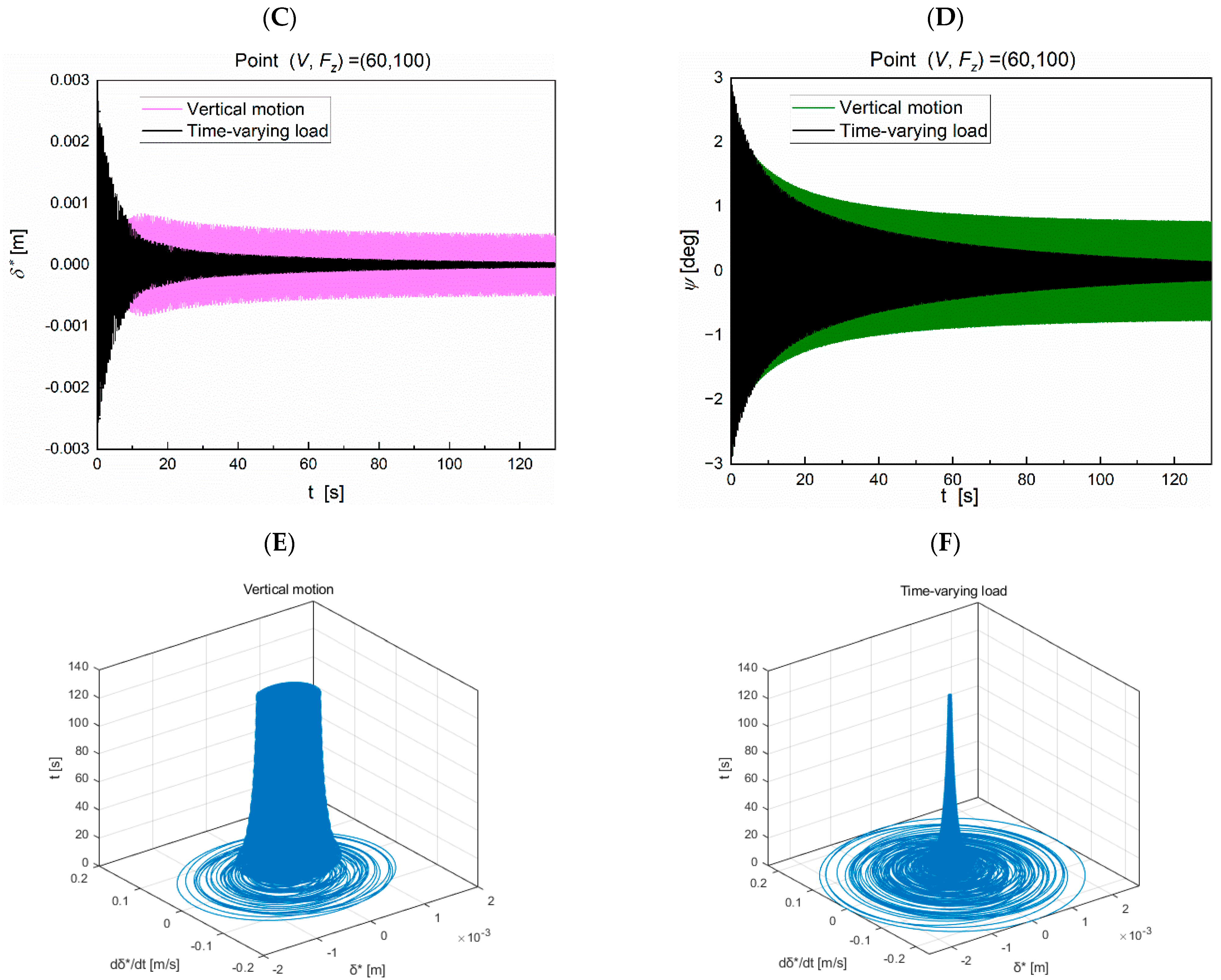
On the other hand, the taxiing speed is set to 60 m/s to investigate the impact of different working conditions on the shimmy amplitude under different loads. It can be found that the vertical motion increases the lateral shimmy amplitude, except for (V, Fz) = (60,100), which is smaller than that under time-varying load, but has little effect on the rotational shimmy amplitude, as shown in Figure 13A,B. Further observing the shimmy amplitude curve of point (V, Fz) = (60,100), it can be found that compared with the case of constant load, the vertical motion increases the lateral shimmy amplitude and presents a stable limit cycle oscillation, as shown in Figure 13E; the disturbance caused by the time-varying load makes the NLG system tend to be stable, in which the lateral shimmy tends to converge—the phase diagram is shown in Figure 13F—and the rotational shimmy amplitude decreases to 0.88 deg.
In summary, the results show that the vertical motion has a significant influence on the lateral shimmy amplitude, but has little effect on the rotational shimmy amplitude, which is consistent with the previous conclusion that the shock absorber stroke has a great influence on the lateral stiffness. Therefore, when considering the working conditions of time-varying load, the design of the NLG system should strengthen the lateral stiffness in the state of full extension to avoid shimmy caused by excessive fluctuation of lateral stiffness caused by the change in shock absorber stroke.

5. Conclusions

In this paper, a nonlinear shimmy mathematical model of NLG with time-varying system stiffness is proposed. The influence of NLG system stiffness change on shimmy is studied, the time-varying characteristics of system stiffness are verified to be necessary for shimmy analysis, and the error of the traditional constant stiffness assumption is corrected. The main conclusions are drawn as follows.
The lateral stiffness and torsional stiffness of the NLG system increase nonlinearly with the increase in the shock absorber stroke, and the lateral stiffness and torsional stiffness in the full compression state are 3.59 times and 1.87 times higher than those in the full extension state, respectively. In the range of two parameters, after considering the change in the system stiffness, the amplitude of lateral shimmy decreases, while the amplitude of rotational shimmy slightly increases, and the influence of the system stiffness on the shimmy stability is that the lateral stiffness plays a leading role.
The time-varying load has an adverse effect on the taxiing stability of the NLG, causing the lateral shimmy amplitude to increase significantly in the shimmy zone. When V reaches 80 m/s, the lateral shimmy amplitude breaks the law that the shimmy amplitude decreases with increasing taxiing speed, while the rotational shimmy amplitude changes little.
Considering the time-varying loads under severe conditions, during the design phase, the lateral stiffness of the nose landing gear system in the fully extended state should be enhanced. The stiffness difference in the nose landing gear system between the fully extended and fully compressed states should be reduced to improve the taxiing stability of the nose landing gear. Additionally, in the shimmy analysis and test process, all possible shock absorber strokes must be included.
This paper reveals the mechanism by which time-varying loads affect shimmy through a dual path of “load amplitude” and “vertical motion–stiffness coupling”. Future research will further explore the influence of the actual aircraft ground taxi response spectrum on the shimmy stability domain.

Author Contributions

Conceptualization, Y.J. and J.S.; Investigation, Y.J., J.S. and S.Z.; Methodology, Y.J. and B.J.; Project administration, B.J.; Software, Y.J.; Supervision, B.J.; Writing—original draft, Y.J.; Writing—review and editing, B.J. All authors have read and agreed to the published version of the manuscript.

Funding

This work was funded by the Civil Aircraft Special Project of the MIIT, grant number JZ025-XY-003.

Institutional Review Board Statement

Not applicable.

Informed Consent Statement

Not applicable.

Data Availability Statement

The data presented in this study are available on request from the corresponding author.

Acknowledgments

The authors gratefully acknowledge the research grant provided by the Civil Aircraft Special Project of the MIIT (Grant No. JZ025-XY-003) in support of this work.

Conflicts of Interest

Authors Yiyao Jiang, Jiyong Sun, Sheng Zhong were employed by the AVIC Aircraft Landing Gear Co., Ltd. The remaining authors declare that the research was conducted in the absence of any commercial or financial relationships that could be construed as a potential conflict of interest.

References

  1. William, J. Moreland The Story of Shimy. J. Aeronaut. Sci. 1954, 21, 793–808. [Google Scholar]
  2. Coetzee, E. Shimmy in Aircraft Landing Gear. Airbus Rep. 2006, 1–11. [Google Scholar]
  3. Gordon, J.T. Perturbation Analysis of Nonlinear Wheel Shimmy. J. Aircr. 2002, 39, 305–317. [Google Scholar] [CrossRef]
  4. Grossman, D.T. F-15 Nose Landing Gear Shimmy, Taxi Test and Correlative Analyses; SAE International: Warrendale, PA, USA, 1980. [Google Scholar] [CrossRef]
  5. Rahmani, M.; Behdinan, K. On the Effectiveness of Shimmy Dampers in Stabilizing Nose Landing Gears. Aerosp. Sci. Technol. 2019, 91, 272–286. [Google Scholar] [CrossRef]
  6. Thota, P.; Krauskopf, B.; Lowenberg, M. Nonlinear Analysis of the Influence of Tyre Inflation Pressure on Nose Landing Gear Shimmy. In Proceedings of the AIAA Modeling and Simulation Technologies Conference, Chicago, IL, USA, 10–13 August 2009. [Google Scholar] [CrossRef]
  7. Howcroft, C.; Lowenberg, M.; Neild, S.; Krauskopf, B.; Coetzee, E. Shimmy of an Aircraft Main Landing Gear with Geometric Coupling and Mechanical Freeplay. J. Comput. Nonlinear Dyn. 2015, 10, 051011. [Google Scholar] [CrossRef]
  8. Kewley, S.; Lowenberg, M.; Neild, S.; Krauskopf, B. Investigation into the Interaction of Nose Landing Gear and Fuselage Dynamics. J. Aircr. 2016, 53, 881–891. [Google Scholar] [CrossRef]
  9. Terkovics, N.; Neild, S.; Lowenberg, M.; Krauskopf, B. Bifurcation Analysis of a Coupled Nose-Landing-Gear-Fuselage System. J. Aircr. 2014, 51, 259–272. [Google Scholar] [CrossRef]
  10. Thota, P.; Krauskopf, B.; Lowenberg, M. Interaction of Torsion and Lateral Bending in Aircraft Nose Landing Gear Shimmy. Nonlinear Dyn. 2009, 57, 455–467. [Google Scholar] [CrossRef]
  11. Thota, P.; Krauskopf, B.; Lowenberg, M. Multi-Parameter Bifurcation Study of Shimmy Oscillations in a Dual-Wheel Aircraft Nose Landing Gear. Nonlinear Dyn. 2012, 70, 1675–1688. [Google Scholar] [CrossRef]
  12. Thota, P.; Krauskopf, B.; Lowenberg, M. Bifurcation Analysis of Nose-Landing-Gear Shimmy with Lateral and Longitudinal Bending. J. Aircr. 2010, 47, 87–95. [Google Scholar] [CrossRef]
  13. Wang, Y.; Zhang, T.; Bian, H.; Yin, Y.; Wei, X. Shimmy Performance Analysis and Parameter Optimization of a Dual-Wheel Nose Landing Gear Coupled with Torsional Nonlinear Energy Sink and Considering Structural Nonlinear Factor. Chaos Solitons Fractals 2024, 187, 115330. [Google Scholar] [CrossRef]
  14. Wang, Y.; Zhang, T.; Yin, Y.; Wei, X. Reducing Shimmy Oscillation of a Dual-Wheel Nose Landing Gear Based on Torsional Nonlinear Energy Sink; Springer: Dordrecht, The Netherlands, 2024; Volume 112, ISBN 0123456789. [Google Scholar]
  15. Feng, G.; Jiang, B.; Ruan, S.; Zhang, M. Analysis of Shimming Performance and Clearance Influence under Manipulation State. J. Vibroeng. 2025, 27, 134–149. [Google Scholar] [CrossRef]
  16. Ruan, S.; Zhang, M.; Hong, Y.; Nie, H. Influence of Clearance and Structural Coupling Parameters on Shimmy Stability of Landing Gear. Aeronaut. J. 2023, 127, 1591–1622. [Google Scholar] [CrossRef]
  17. Rahmani, M.; Behdinan, K. Investigation on the Effect of Coulomb Friction on Nose Landing Gear Shimmy. JVC/J. Vib. Control 2019, 25, 255–272. [Google Scholar] [CrossRef]
  18. Rahmani, M.; Behdinan, K. Parametric Study of a Novel Nose Landing Gear Shimmy Damper Concept. J. Sound Vib. 2019, 457, 299–313. [Google Scholar] [CrossRef]
  19. Cheng, L.; Cao, H.; Zhang, L. Two-Parameter Bifurcation Analysis of an Aircraft Nose Landing Gear Model. Nonlinear Dyn. 2021, 103, 367–381. [Google Scholar] [CrossRef]
  20. Rahmani, M.; Behdinan, K. Structural Design and Optimization of a Novel Shimmy Damper for Nose Landing Gears. Struct. Multidiscip. Optim. 2020, 62, 2783–2803. [Google Scholar] [CrossRef]
  21. Du, X.; Xu, Y.; Liu, Q.; Liu, C.; Yue, X.; Liu, X.; Kurths, J. Shimmy Dynamics in a Dual-Wheel Nose Landing Gear with Freeplay under Stochastic Wind Disturbances. Nonlinear Dyn. 2024, 112, 2477–2499. [Google Scholar] [CrossRef]
  22. Wong, J.; Ryan, L.; Kim, I.Y. Design Optimization of Aircraft Landing Gear Assembly under Dynamic Loading. Struct. Multidiscip. Optim. 2018, 57, 1357–1375. [Google Scholar] [CrossRef]
  23. Skinn, D.; Tipps, D.O.; Rustenburg, J. Statistical Loads Data for MD-82/83 Aircraft in Commuter Operations; U.S. Department of Transportation Federal Aviation Administration: Washington, DC, USA, 1999. [Google Scholar]
  24. Sura, N.K.; Suryanarayan, S. Lateral Response of Nonlinear Nose-Wheel Landing Gear Models with Torsional Free Play. J. Aircr. 2007, 44, 1991–1997. [Google Scholar] [CrossRef]
  25. Liu, J.; Ou, H.; He, J.; Wen, G. Topological Design of a Lightweight Sandwich Aircraft Spoiler. Materials 2019, 12, 3225. [Google Scholar] [CrossRef] [PubMed]
  26. Wang, J.; Li, Y.; Hu, G.; Yang, M. Lightweight Research in Engineering: A Review. Appl. Sci. 2019, 9, 5322. [Google Scholar] [CrossRef]
  27. Huang, R.; Riddle, M.; Graziano, D.; Warren, J.; Das, S.; Nimbalkar, S.; Cresko, J.; Masanet, E. Energy and Emissions Saving Potential of Additive Manufacturing: The Case of Lightweight Aircraft Components. J. Clean. Prod. 2016, 135, 1559–1570. [Google Scholar] [CrossRef]
  28. Ahmad, M.A.; Rafiq, H.; Shah, S.I.A.; Khan, S.A.; Rizvi, S.T.U.I.; Shams, T.A. Selection Methodology of Composite Material for Retractable Main Landing Gear Strut of a Lightweight Aircraft. Appl. Sci. 2022, 12, 5689. [Google Scholar] [CrossRef]
  29. Rahmani, M.; Behdinan, K. Studying the Effect of Freeplay on Nose Landing Gear Shimmy Using a Fully Nonlinear Model. In Proceedings of the ASME 2018 International Design Engineering Technical Conferences and Computers and Information in Engineering Conference, Quebec City, QC, Canada, 26–29 August 2018; Volume 6, pp. 1–11. [Google Scholar] [CrossRef]
  30. Hu, Y.; Hu, Y.; Lin, S.; Ma, J.; Li, S.; Li, J.; Wen, J. Theoretical Modeling and Dynamic Characteristics Analysis of Piezoelectric Inertial Actuator. Int. J. Mech. Sci. 2022, 225, 107363. [Google Scholar] [CrossRef]
  31. Wang, Y.; Wu, J.; Zhang, N.; Mo, W. Dynamics Modeling and Shift Control of a Novel Spring-Based Synchronizer for Electric Vehicles. Mech. Mach. Theory 2022, 168, 104586. [Google Scholar] [CrossRef]
  32. Li, Y.L.; Liu, B.F.; Wu, G.; Liu, Z.Q.; Ding, J.F.; Abubakar, S. Intelligent Prediction on Air Intake Flow of Spark Ignition Engine by a Chaos Radial Basis Function Neural Network. J. Cent. South Univ. 2020, 27, 2687–2695. [Google Scholar] [CrossRef]
  33. Yager, T.J. SAE TECHNICAL Aircraft Nose Gear Shimmy Studies. 2018. Available online: https://ntrs.nasa.gov/citations/19950062072 (accessed on 9 September 2025).
  34. Yin, Y.; Xu, K.; Nie, H.; Wei, X.; Wang, H. Dynamics Analysis of Spatial Landing-Gear Mechanism with Hinge Clearance and Axis Deviation. J. Aircr. 2021, 58, 30–42. [Google Scholar] [CrossRef]
  35. Mustashin, M.S.; Rahmani, M.; Behdinan, K. Experimental Characterization of a Novel Nose Landing Gear Shimmy Damper Using a Small-Scale Test Rig. Aerosp. Sci. Technol. 2021, 112, 106625. [Google Scholar] [CrossRef]
  36. Smiley, R.F. Correlation, Evaluation, and Extension of Linearized Theories for Tire Motion and Wheel Shimmy; NASA Technical Note 3632; NASA Technical Reports Server: Washington, DC, USA, 1956; pp. 1–145. [Google Scholar]
  37. Takács, D.; Orosz, G.; Stépán, G. Delay Effects in Shimmy Dynamics of Wheels with Stretched String-like Tyres. Eur. J. Mech. A/Solids 2009, 28, 516–525. [Google Scholar] [CrossRef]
  38. Ran, S.; Besselink, I.J.M.; Nijmeijer, H. Application of Nonlinear Tyre Models to Analyse Shimmy. Veh. Syst. Dyn. 2014, 52, 387–404. [Google Scholar] [CrossRef]
  39. Khapane, P.D. Soimulation of Asymmetric Landing and Typical Ground Maneuvers for Large Transport Aircraft. Aerosp. Sci. Technol. 2003, 7, 611–619. [Google Scholar] [CrossRef]
  40. Jiang, Y.; Feng, G.; Liu, P.; Yuan, L.; Ding, J.; Jiang, B. Evaluation of Joint Clearance Effects on the Shimmy of Nose Landing Gear. Aerospace 2023, 10, 772. [Google Scholar] [CrossRef]
  41. Orlando, C. Nose Landing Gear Simple Adaptive Shimmy Suppression System. J. Guid. Control Dyn. 2020, 43, 1298–1312. [Google Scholar] [CrossRef]
  42. Sanches, L.; Guimarães, T.A.M.; Marques, F.D. Nonlinear Energy Sink to Enhance the Landing Gear Shimmy Performance. Acta Mech. 2021, 232, 2605–2622. [Google Scholar] [CrossRef]
  43. Jiang, Y.; Feng, G.; Tang, H.; Zhang, J.; Jiang, B. Effect of Coulomb Friction on Shimmy of Nose Landing Gear under Time-Varying Load. Tribol. Int. 2023, 188, 108828. [Google Scholar] [CrossRef]
Figure 1. The physical model of the NLG.
Aerospace 12 00926 g001
Figure 2. Different views on the simplified structure of the NLG.
Aerospace 12 00926 g002
Figure 3. Oleo-pneumatic shock absorber structure.
Aerospace 12 00926 g003
Figure 4. Positive and reverse stroke oil damping coefficient of shock absorber.
Aerospace 12 00926 g004
Figure 5. Comparison of shimmy amplitude calculated by Matlab/Simulink model with that of Thota et al. [10]. (A) and (B) represent the amplitude of rotational and lateral shimmy, respectively.
Aerospace 12 00926 g005
Figure 6. Structure diagram of the NLG.
Aerospace 12 00926 g006
Figure 7. Full-scale static stiffness test of NLG.
Aerospace 12 00926 g007
Figure 8. Relationship between NLG stiffness and shock absorber stroke; (A) lateral stiffness, (B) torsional stiffness.
Aerospace 12 00926 g008
Figure 9. (A) Time-varying load and (B) shock absorber stroke curve.
Aerospace 12 00926 g009
Figure 10. Influence of system stiffness change on NLG shimmy amplitude: (A) amplitude of lateral shimmy; (B) amplitude of rotational shimmy; (C,D) are 2D curves corresponding to (A); (E,F) are 2D curves corresponding to (B).
Aerospace 12 00926 g010aAerospace 12 00926 g010b
Figure 11. The influence of coupling time-varying load and system stiffness on the amplitude of NLG shimmy. (A) Amplitude of lateral shimmy; (B) amplitude of rotational shimmy; (C,D) depict corresponding 2D curves for time-varying load conditions.
Aerospace 12 00926 g011
Figure 12. The influence of various working conditions on shimmy under different taxiing speeds: (A,B) represent lateral and rotational shimmy amplitudes, (C,D) are time history curves for lateral and rotational amplitudes at point (100, 200), and (E,F) are phase diagrams corresponding to (C).
Aerospace 12 00926 g012aAerospace 12 00926 g012b
Figure 13. The influence of various working conditions on shimmy at different vertical loads: (A,B) represent lateral and rotational shimmy amplitudes, (C,D) are time history curves for lateral and rotational amplitudes at point (60, 100), and (E,F) are phase diagrams corresponding to (C).
Aerospace 12 00926 g013aAerospace 12 00926 g013b
Table 1. Parameter list for NLG.
SymbolParameterValueUnit
Structure parameters
lg0Fully extended height of NLG2.82m
φRake angle0.1571rad
eMechanical trail0.12m
I ψ Moment of inertia of strut w.r.t. Z-axis 100kg·m2
I δ Moment of inertia of strut w.r.t. X-axis600kg·m2
k ψ Torsional stiffness of strut3.8 × 105N·m/rad
k δ Lateral stiffness of strut6.1 × 106N·m/rad
c ψ Torsional damping of strut300N·m·s/rad
c δ Lateral damping of strut300N·m·s/rad
Tire parameters
RRadius of tire0.362m
LTire relaxation length0.3m
hContact patch length0.1m
k α Self-aligning coefficient of elastic tire1.0m/rad
k λ   Restoration coefficient of elastic tire0.002rad−1
k v Vertical stiffness of tire4 × 106N/m
α m Slip angle limit0.1745rad
c λ Damping coefficient of elastic tire270N·m2/rad
IWheel moment of inertia0.1kg·m2
DDistance between the wheel centers0.1m
Shock absorber parameters
Pa0Initial gas pressure2,425,000Pa
V0Initial gas volume3.059 × 103m3
AaPressure area 7.11 × 10⁻³m2
ρOil density860kg/m3
PatmAtmospheric pressure1,010,000Pa
nAir variability index1.1-
kstrutStructural limited stiffness1.96 × 108N/m
SmaxMaximum stroke0.43m
SStroke-m
Input parameters
FzNose wheel vertical load20–400kN
VTaxiing speed10–120m/s
Disclaimer/Publisher’s Note: The statements, opinions and data contained in all publications are solely those of the individual author(s) and contributor(s) and not of MDPI and/or the editor(s). MDPI and/or the editor(s) disclaim responsibility for any injury to people or property resulting from any ideas, methods, instructions or products referred to in the content.