Article

Fixed-Time Attitude Control for a Flexible Space-Tethered Satellite via a Nonsingular Terminal Sliding-Mode Controller

1
Department of Control Science and Engineering, Harbin Institute of Technology, Harbin 150001, China
2
CSSC System Engineering Research Institute, Beijing 100094, China
3
Suzhou Research Institute of HIT, Suzhou 215104, China
*
Author to whom correspondence should be addressed.
Aerospace 2025, 12(10), 907; https://doi.org/10.3390/aerospace12100907
Submission received: 21 August 2025 / Revised: 23 September 2025 / Accepted: 29 September 2025 / Published: 9 October 2025
(This article belongs to the Special Issue Application of Tether Technology in Space)

Abstract

This paper presents a rigid–flexible coupling dynamic modeling framework and a fixed-time control strategy for a flexible space-tethered satellite (STS) system. A high-fidelity rigid–flexible coupling dynamic model of STS is developed using the finite element method, accurately capturing the coupled attitude dynamics of the satellite platform and flexible tether. Leveraging a simplified representation of the STS model, a nonsingular terminal sliding-mode controller (NTSMC) is synthesized via fixed-time stability theory. Uncertainties and disturbances within the system are compensated for by a radial basis function neural network (RBFNN), ensuring strong robustness. The controller’s fixed-time convergence property—with convergence time independent of initial conditions—is established using Lyapunov stability theory, enabling reliable operation in complex space environments. Numerical simulations implemented on the STS rigid–flexible coupling model validate the controller’s efficacy. Comparative analyses demonstrate superior tracking performance and enhanced practicality over conventional sliding-mode controllers, especially in the aspect of chattering suppression for the satellite thrusters.

1. Introduction

The space-tethered satellite (STS) system, a novel multi-body spacecraft configuration typically comprising a primary main satellite and multiple son satellites interconnected through kilometer-scale high-strength flexible tethers, has garnered significant research interest in aerospace engineering [1,2]. This innovative architecture demonstrates substantial potential for advanced space applications, particularly in large-scale orbital structure assembly, active debris-removal missions, and precision orbital rendezvous and docking operations [3]. The system’s unique combination of structural flexibility and mission scalability has motivated comprehensive investigations across three critical domains: satellite configuration frameworks [4,5], dynamic modeling methodologies [6,7], and flight control architectures [8,9].
In conventional STS dynamic modeling, the dumbbell model has been widely adopted for theoretical derivation and subsequent analysis, wherein taut tethers during deployment operations are typically idealized as rigid massless rods, and the overall system has three degrees of freedom: tether length, in-plane angle, and out-of-plane angle [10,11]. This oversimplification fundamentally neglects the system’s inherent flexible characteristics, significantly compromising the fidelity of dynamic behavior representation while exhibiting critical limitations in complex real-world space scenarios. To address these limitations in the dynamic modeling of such complex spacecraft, recent scholarly efforts have progressively shifted toward implementing advanced flexible modeling approaches, particularly Kane’s method [12,13], lumped-mass parameterization methods [14,15], absolute nodal coordinate formulation (ANCF) [16,17], and finite element modeling (FEM) techniques [18,19], to enhance the physical accuracy of tethered system dynamics. Among mainstream modeling methods, the finite element method offers distinct advantages in small-deformation scenarios, characterized by high precision, reliability, and considerable practical engineering value. Its computational efficiency has cemented its role in spacecraft dynamics modeling. Owing to the structural and operational particulars of tethered satellites, FEM is highly applicable to their investigation, prompting numerous scholars to deploy it for related modeling and analytical studies. In the study [19], Li et al. propose a nodal-position FEM with implicit symplectic Gaussian–Legendre Runge–Kutta integration to resolve numerical instability and error accumulation in long-term elastic tether dynamics modeling, ensuring energy conservation and global stability for tethered spacecraft deorbiting simulations. In [20], a nodal-position FEM-based rigid–flexible dynamic model is constructed to simulate the interactions between a tether, a satellite and space debris. Furthermore, an adaptive sliding-mode control strategy is developed for robust attitude regulation, thereby enhancing the reliability of space debris deorbiting missions. Zhang and Zhu employ a FEM to develop a high-fidelity nodal-position dynamic model of flexible tethered space systems and propose a finite element-formulated optimal control framework to regulate their geometrical profile through moving-horizon variational principles [21].
The control of STS systems primarily encompasses two aspects: attitude regulation and deployment control. Both fundamentally constitute reference tracking problems, where the controller drives system states (including both attitude angles and tether length) to converge to prescribed target values with specified dynamics. Sliding-mode control (SMC) is widely adopted for its robust performance and resistance to interference, and it shows promising application prospects in spacecraft control [22,23]. The convergence time of the traditional terminal sliding-mode method is closely dependent on the system’s initial state, resulting in long convergence times in complex scenarios. The fixed-time stability theory effectively addresses this issue by proving that the system can determine an upper bound for convergence time, independent of the initial state. This offers distinct advantages in satellite control during complex mission scenarios [24]. Previous studies have explored the application of fixed-time SMC to the STS system. Tao et al. proposed a decentralized control framework integrating nonsingular SMC and coordinated thrust-motor strategies for triangle tethered formation systems, enabling fixed-time deployment convergence and precise tether-satellite matching [25]. Ref. [26] designs a fixed-time terminal SMC and tension-thrust coordination strategy for a Lagrangian-modeled spinning tether system in high-eccentricity orbits, enabling artificial gravity generation with lightweight design, controlled spin velocity, and target gravity achievement. Ref. [27] develops a novel fractional-order fixed-time sliding-mode controller for space tether deployment and proves global stability and demonstrating superior rapidity and steady-state performance applicable to underactuated systems.
The radial basis function (RBF) neural network can be used for the compensation of unknown terms in the system and has a strong ability to approximate nonlinear systems [28]. It is widely used in fields such as robot trajectory tracking [29] and spacecraft attitude control [30]. In [31], Li et al. propose an adaptive super-twisting sliding-mode controller with fractional-order terminal attractor and RBF neural network-based adaptive law for fast, stable deployment of STS, addressing in-plane/out-of-plane motion uncertainties and disturbances while ensuring finite-time convergence via Lyapunov analysis. In [32], Zhong and Xu develop an RBFNN-based terminal sliding-mode controller for tethered space-tug thrust regulation, where RBFNN estimates nonlinear model discrepancies and SMC enables rapid attitude tracking, validated by simulations demonstrating stabilized tug-target dynamics with thrust saturation and tether slackness avoidance.
Based on established STS dynamic modeling methods and control strategies, this study adopts a finite element-based rigid–flexible coupling dynamic model that effectively captures both tether flexibility and satellite attitude dynamics. Focusing on core mission requirements, we extract essential in-plane attitude parameters from the complex model to derive a simplified model for controller design. By integrating fixed-time stability theory with RBF neural network compensation, we develop a novel nonsingular terminal sliding-mode controller. The controller’s effectiveness is verified through application to the complete rigid–flexible coupled model, demonstrating precise attitude control and fixed-time convergence capability that meets stringent space mission requirements.
The structure of this paper is as follows: Section 1 presents the research background, reviews current advances in tethered systems, and outlines the paper’s objectives. Section 2 presents the dynamic modeling of the STS system, introducing the rigid–flexible coupling dynamic model based on the finite element method followed by simplifications to facilitate controller design. Section 3 discusses the design of a fixed-time sliding-mode controller incorporating a neural network and provides the necessary theoretical foundations and stability proofs for the controller. Section 4 offers numerical simulations of the dynamic model and controller, comparing the results with those of a classical nonsingular terminal sliding-mode controller to assess its convergence behavior and dynamic performance. Finally, Section 5 summarizes the findings and contributions of this paper.

2. Flexible Dynamic Model of STS

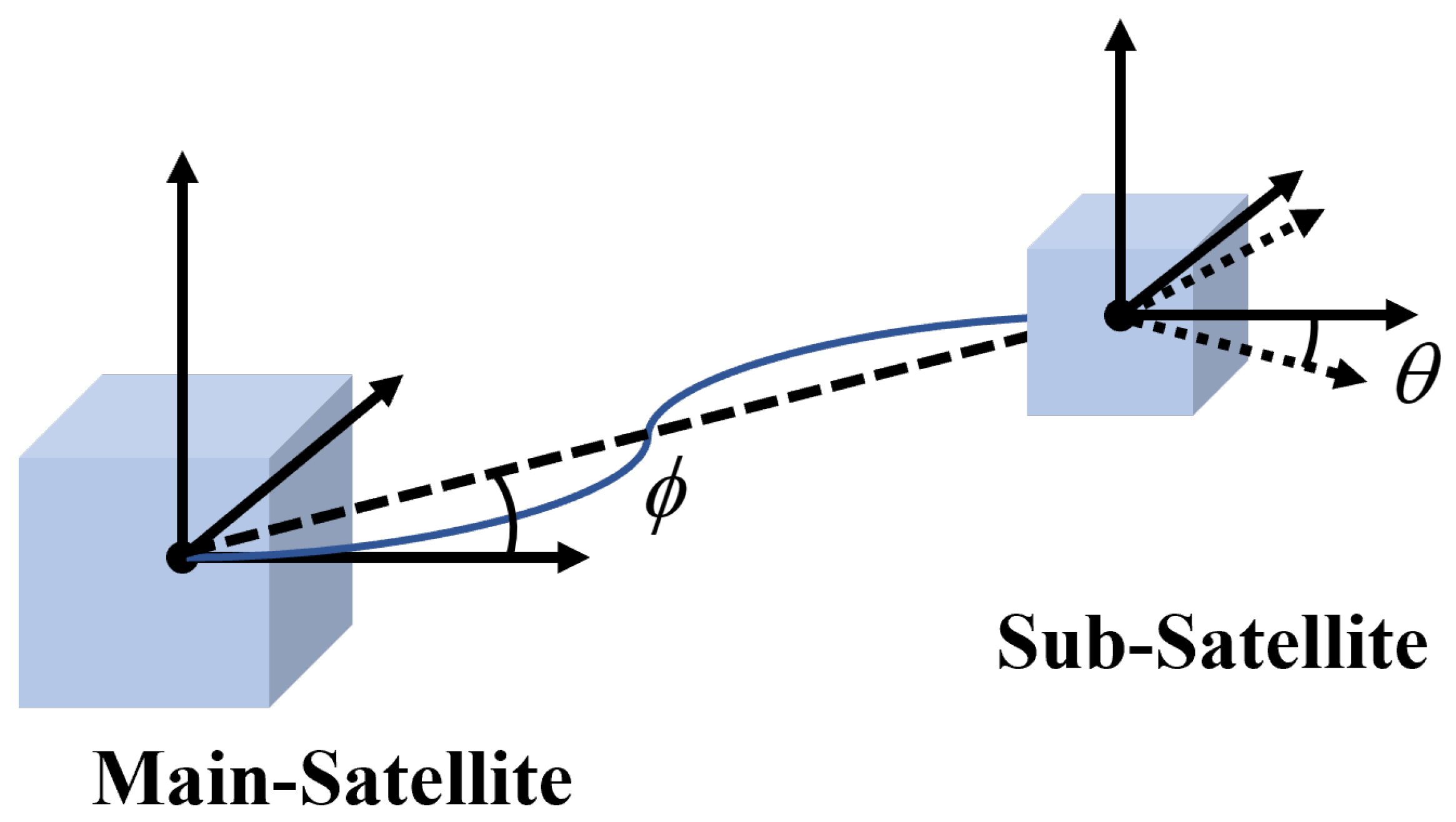
The STS system structure and coordinate system definition studied in this paper are shown in Figure 1. We define the coordinate system as follows: geocentric inertial coordinate system O X Y Z , body-fixed coordinate system O m X m Y m Z m , and O s X s Y s Z s of the main satellite and sub-satellite. O is at the Earth’s center of mass, the coordinate system O X Y Z is determined by the equatorial plane, and the celestial rotation axis is determined according to the right-hand rule. For the two satellite body coordinate systems, their origins are both located at the satellite’s center of mass, O m X m and O s X s point to Earth along geometric nadir vector, O m Y m and O s Y s are perpendicular to port-side structural planes of the satellite, and O m Z m and O s Z s are also determined by the right-hand rule.
The rigid–flexible coupling dynamic model of the STS system will be modeled using the nodal position coordinate method [19,20]. Following standard finite element assembly procedures, the tether’s governing equation is derived as
M t X ¨ t + K t X t = F t , S + F t , G
where M t (mass matrix), X t (position vector), K t (stiffness matrix), F t , S (elastic force vector), and F t , G (gravitational force vector) are the kinetic parameters of the tether’s FEM assembled procedure.
Next, we build the translation and attitude motion model of the satellite. First, the translational motion of the main satellite in the coordinate system O X Y Z is modeled as
M m X ¨ m = F m , G + F m , P
where M m is mass matrix of main-satellite; X ¨ m is the acceleration vector; and the F m , G and F m , P are, respectively, the gravity vector exerted on the satellite and the tensile force applied to the main satellite by the tether.
And attitude motion of the main satellite satisfies
J m ω ˙ m + ω m × ( J m ω m ) = T m , P + T m , C
where J m represents the inertia matrix of the main satellite; T m , P is the torque vector generated by the tension of the tether; T m , C is the control torque vector; and ω m and ω ˙ m are the angular velocity and angular acceleration of the main satellite in the geocentric inertial coordinate system, respectively.
When the satellite maneuvers at large angles, singularities may occur when the attitude is expressed using Euler angles. To address this, quaternions are introduced to represent the attitude transformation. Based on the established kinematic relationship between angular velocity and Euler parameters [33], Equation (3) can be transformed into the following form:
G m J m G m Q ¨ m + 2 Q ˙ m J m G m Q ˙ m C m , q m = G m T m , P + T m , C
where Q m = q m , 0 , q m , 1 , q m , 2 , q m , 3 is the attitude quaternions; G m = 2 q m , q m , 0 I 3 × 3 q ˜ m is the attitude transition matrix, with q m = q m , 1 , q m , 2 , q m , 3 and q ˜ m = diag { q m , 1 , q m , 2 , q m , 3 } ; C m , q m is the Jacobian matrix of constraint C m ; and the attitude quaternions Q m needs to satisfy the quaternions constraint, which takes the following form:
C m = q m , 0 2 + q m q m 1 = 0 .
Similar to main satellite model (2)–(5), the model of the sub-satellite can be expressed as
M s X ¨ s = F s , G + F s , P G s J s G s Q ¨ s + 2 Q ˙ s J s G s Q ˙ s C s , q s = G s T s , P + T s , C C s = q s , 0 2 + q s q s 1 = 0
where the definitions of all parameters are the same as in model (2)–(5) and correspond one-to-one, the meaning of each variable will not be described separately here. For clarity, the subscripts “m” and “s” are used to represent the main satellite and the sub-satellite, respectively.
Next, establish the coupled motion constraint relationship between the tether and the two satellites. The equations are similarly distinguished by subscripts denoting the satellites, while the constraint equations between the satellite and tether endpoints are expressed as
D m = X m + Z m ( Q m ) ρ m b X t , m = 0 D s = X s + Z s ( Q s ) ρ s b X t , s = 0 .
The dynamic model of the tethered satellite system in the full deployment phase is derived from the coupled governing Equations (1)–(7), which collectively describe the system’s hybrid rigid–flexible dynamics. These equations are formulated as
M t X ¨ t + K t X t + D m , X t λ d m + D s , X t λ d s = F t + F t , G M m X ¨ m + D m , X m λ d m = F m , G M s X ¨ s + D s , X s λ d s = F s , G G m J m G m Q ¨ m + 2 Q ˙ m J m G m Q ˙ m C m , q m + C m , q m λ c m + D m , q m λ d m = G m ( T m , C + T m , P ) G s J s G s Q ¨ s + 2 Q ˙ s J s G s Q ˙ s C s , q s + C s , q s λ c s + D s , q s λ d s = G s ( T s , C + T s , P ) C m = q m , 0 2 + q m q m 1 = 0 C s = q s , 0 2 + q s q s 1 = 0 D m = X m + Z m ( Q m ) ρ m b X t , m = 0 D s = X s + Z s ( Q s ) ρ s b X t , s = 0
where F t is the total elastic force after the tether connects the two satellites; D m , q m , D m , X t , D m , X m , D s , q s , D s , X t and D s , X s are the Jacobian matrices similar to C m , q m and C s , q s , corresponding to the constraints D m and D s respectively; and λ c m , λ c s , λ d m , λ d s are Lagrange multipliers. The introduction of Z ( · ) parameterizes the transformation matrix from the body-fixed coordinate system O m X m Y m Z m and O s X s Y s Z s to the coordinate system O X Y Z , having the following form with I as the identity matrix:
Z m ( Q m ) = 2 q m , 0 2 1 I + 2 q m q m + 2 q m , 0 q ˜ m Z s ( Q s ) = 2 q s , 0 2 1 I + 2 q s q s + 2 q s , 0 q ˜ s .
Remark 1. 
The parameter in the simultaneous Equation (8) of the STS system employs the high-dimensional dynamic model originally formulated in [20], including the system matrices, force vectors, constraints, and quaternion representations. For compactness, their full symbolic expansions are not reproduced here.

3. Controller Design

3.1. Preliminaries and Simplified Model

3.1.1. Fixed-Time-Stable

Lemma 1 
([34]). Consider the following nonlinear system:
x ˙ = ρ ( x ( t ) )
where x = [ x 1 , x 2 , , x n ] R n represents the system state variable and x ( 0 ) = x 0 . Assume ρ ( x ) : R n R n is a homogeneous vector field with a bi-limit at associated triples ( r 0 , k 0 , ρ 0 ) and ( r , k , ρ ) . If the origins of systems x ˙ = ρ ( x ) , x ˙ = ρ 0 ( x ) , x ˙ = ρ ( x ) are globally asymptotically stable equilibria, then the following inference holds: (a) The system (9) is fixed-time-stable and the solution of system could converge to the origin by selecting appropriate values such that k 0 < 0 < k , system (9) is fixed-time-stable, and its solutions converge to the origin of the system within a fixed time. (b) Real numbers d V and d V 0 are selected hat satisfy d V > max { r , i } and d V 0 > max { r 0 , i } , i = 1 , 2 , , n . There exists a continuous positive definite function V such that, for any function x δ V δ x i , it is homogeneous with respect to the bi-limit of the associated triples ( r 0 , d V 0 r 0 , i , δ V δ x i ) and ( r , d V r , i , δ V δ x i ) , and this function is negative definite.
Lemma 2 
([34]). Consider the following perturbation system:
x ˙ = ρ x ( t ) , Δ
where Δ = [ Δ 1 , Δ 2 , , Δ n ] R n is the disturbance vector and ρ ( x , Δ ) is homogeneous in the bi-limit vector fields ( ( r 0 , ϱ 0 ) , d 0 , ρ 0 ) and ( ( r , ϱ ) , d , ρ ) , with the ϱ 0 and ϱ being the weight vectors associated with the perturbation Δ. The function V ( x ) , which is given by Lemma 1, satisfies the inequality:
δ V δ x ρ ( x , Δ ) c v Λ V ( x ) d V o + d 0 d V 0 + V ( x ) d V + d d V + c Δ j = 1 n Λ | Δ j | d V 0 + d 0 ϱ 0 , j + | Δ j | d V + d ϱ , j
where c v and c Δ are positive real numbers, Λ ( a , b ) = a ( 1 + b ) / ( 1 + a ) and a , b R + .
Lemma 3 
([35]). For any x , y R , and p > 1 , q > 1 , ( p 1 ) ( q 1 ) = 1 and δ > 0 , the following inequality holds:
x y δ p p | x | p + 1 q δ q | y | q .
Lemma 4 
([36]). For system x ˙ = f ( x ) , assume a positive definite Lyapunov function V ( x ) that is continuous, and its derivative satisfies:
V ˙ ( x ) γ 1 V c 1 ( x ) γ 2 V c 2 ( x ) + c 3
where γ i > 0 ( i = 1 , 2 ) , 0 < c 1 < 1 , c 2 > 1 and c 3 > 0 . The system (9) is therefore considered practical fixed-time-stable, and system variable x will converge to neighborhood with fixed time, with the neighborhood Q and convergence time T bounded by
Q = x | V ( x ) min c 3 ( 1 d ) γ 1 1 c 1 , c 3 ( 1 d ) γ 2 1 c 2 T T max = 1 d γ 1 ( 1 c 1 ) + 1 d γ 2 ( c 2 1 )
where 0 < d < 1 is a positive constant.
Notation 1. 
For notational clarity, this paper establishes the following equivalent representations for given vectors x = [ x 1 , x 2 , , x n ] R n and nonnegative constant r R n :
sig r ( x ) = | x | r sign ( x ) | x | r = [ | x 1 | r , | x 2 | r , , | x n | r ] .

3.1.2. RBFNN Approximation

The RBFNN is adopted to fit and estimate the unknown modes of the tethered satellite system. The output of the RBFNN can be described as
f N ( z ) = W * Φ ( z ) + ε
where W * = [ W 1 * , W 2 * ] is the ideal weight matrix of RBF; ε is the bounded approximation error that satisfies | ε | ε max ; z = [ e 1 , e 2 ] is the input matrix, whose variables will be defined later; and Φ ( z ) = [ Φ 1 ( z ) , Φ 2 ( z ) , , Φ l ( z ) ] is output of the NN basis function and satisfies:
Φ i j = exp ( ( z i μ i j ) ( z i μ i j ) b i j 2 )
where μ i = [ μ i 1 , μ i 2 , , μ i l ] and b i = [ b i 1 , b i 2 , , b i l ] are the central parameter and width of the NN basis function, respectively, and l > 0 indicates the node number of NN.

3.1.3. Simplified Model

In the finite element model provided previously, the system states require updating through an iterative solution procedure using the generalized-alpha method. Consequently, such models lack an explicit state-space representation, making traditional controller design challenging. Considering controller design requirements and practical operational constraints, this study focuses on in-plane tether release dynamics through a reduced-order planar model. The system state thus comprises exclusively the translational displacement of the sub-satellite within the orbital plane and its rotation about the axis O s X s . These essential motions are abstracted as two key attitude parameters: the in-plane angle and satellite attitude angle (graphically defined in Figure 2). This abstraction yields a control-oriented simplified STS model for subsequent controller design. Within this framework, all parameters except the system’s mass matrix are treated as unmodeled uncertainties, actively estimated and compensated through RBF neural network adaptation. The resulting simplified dynamics are formulated as follows:
M q ¨ f N = u
M = M 1 M 2 = m m m s m m + m s L 0 1 6 m s a 2
where q = [ ϕ , θ ] is the system state that includes the in-plane angle of STS and the attitude angle of the sub-satellite; f N represents the uncertain mode of the STS model, which is estimated by the RBFNN; u = [ u ϕ , u θ ] is the output vector of the controller, including the in-plane thrust and the in-plane torque of the sub-satellite; m m and m s represent the masses of the main satellite and the sub-satellite, respectively; and L 0 is the tether length in the initial state, and the a is the side length of a cube-structured sub-satellite.
Remark 2. 
Finite element models present challenges for direct controller design. In prior studies on flexible dynamics control, a simplified representation is typically employed for controller synthesis [13,20]. The resulting controller is subsequently applied to the flexible dynamic model, with an observer estimating and compensating for modeling errors. This approach enhances computational efficiency while maintaining acceptable accuracy.

3.2. Fixed-Time NTSM Controller

Define the STS system attitude error as
e 1 = q q d e 2 = q ˙
where e 1 = [ e 11 , e 12 ] , e 2 = [ e 21 , e 22 ] , and q d is a constant value for the target attitude. Take the derivative of it and substitute it into Equation (17) to obtain
e 1 ˙ = e 2 e 2 ˙ = M 1 ( u + f N ) .
The fixed-time nonsingular terminal sliding-mode variable designed as shown below is
s = e 2 + K 1 ζ 1 ( e 1 ) + K 2 ζ 2 ( e 1 )
where K 1 > 0 , K 2 > 0 , and the ζ 1 ( e 1 ) and ζ 2 ( e 1 ) have the following form:
ζ 1 ( e 1 ) = l 1 e 1 + m 1 sig 2 ( e 1 ) , | e 1 | σ ϕ sig p 1 ( e 1 ) , | e 1 | > σ ϕ ζ 2 ( e 1 ) = l 2 e 1 + m 2 sig 2 ( e 1 ) , | e 1 | σ ϕ sig p 2 ( e 1 ) , | e 1 | > σ ϕ
where l 1 = ( 2 p 1 ) σ ϕ p 1 1 , l 2 = ( 2 p 2 ) σ ϕ p 2 1 , m 1 = ( p 1 1 ) σ ϕ p 1 2 , m 2 = ( p 2 1 ) σ ϕ p 2 2 , p 1 and p 2 are freely defined parameters that must satisfy p 1 > 1 , 0 < p 2 < 1 , and σ ϕ is a small positive constant.
Remark 3. 
By transitioning the sliding-mode variable to conventional sliding-mode operation when | e 1 | σ ϕ , the proposed method eliminates the singularity issue inherent in traditional fixed-time algorithms. This approach simultaneously guarantees the continuity of the control signal’s first-order derivative. The appropriate selection of l i and m i ( i = 1 , 2 ) ensures this derivative continuity, while the terms ζ i ( i = 1 , 2 ) are key to resolving the singularity.
By taking the derivative of Formula (20), the following formula is obtained:
s ˙ = M 1 ( u + f N ) + K 1 ζ ˙ 1 ( e 1 ) + K 2 ζ ˙ 2 ( e 1 )
where
ζ ˙ 1 ( e 1 ) = l 1 e 2 + 2 m 1 | e 1 | e 2 , | e 1 | σ ϕ p 1 | e 1 | p 1 1 e 2 , | e 1 | > σ ϕ ζ ˙ 2 ( e 1 ) = l 2 e 2 + 2 m 2 | e 1 | e 2 , | e 1 | σ ϕ p 2 | e 1 | p 2 1 e 2 , | e 1 | > σ ϕ
The RBFNN-based fixed-time sliding-mode controller is proposed as follows:
u = M K 1 ζ ˙ 1 ( e 1 ) + K 2 ζ ˙ 2 ( e 1 ) + K 3 sig α s ( s ) + sig β s ( s ) W ^ Φ ε max sign ( s )
where K 3 > 0 , α s ( 1 2 , 1 ) and β s ( 1 , 2 3 ) ; W ^ is the estimated value of W * in NN; and its adaptive law update form is structured as
W ^ ˙ = Γ N Φ
where N = M 1 K 3 sig 2 α s 1 ( s ) + sig 2 β s 1 ( s ) and Γ is a symmetric positive definite constant matrix.

3.3. Stability Analysis

Theorem 1. 
For the system (17) and the proposed controller (22), the system error could converge to a small neighborhood within a fixed time. The convergence time satisfies the following inequality:
T T t = T s + T d
where T s is the maximum convergence time to the sliding surface and T d to the equilibrium point, with both being initial-state-independent.
Proof. 
The proof is structured in two parts, corresponding to the dynamic behavior of the system error trajectory.
Part 1: First, it is established that the sliding-mode variable s converges to a predefined neighborhood of the origin s = 0 within a fixed-time T s , in accordance with fixed-time stability theory.
The following Lyapunov function is selected:
V = 1 2 K 3 s 2 α s + 1 2 K 3 s 2 β s + 1 2 W ˜ Γ 1 W ˜
where W ˜ = W * W ^ is the estimation error vector of RBF and the derivative form of V can be obtained:
V ˙ = K 3 α s sig 2 α s 1 ( s ) + β s sig 2 β s 1 ( s ) s ˙ + W ˜ Γ 1 W ˜ ˙ = K 3 2 α s s 3 α s 1 + β s s 3 β s 1 + α s s 2 α s + β s 1 + β s s α s + 2 β s 1 K 3 α s sig 2 α s 1 ( s ) + β s sig 2 β s 1 ( s ) ε max + N ( s ) W ˜ Φ + ε W ˜ Γ 1 W ^ ˙ K 3 2 α s s 3 α s 1 + β s s 3 β s 1 + α s s 2 α s + β s 1 + β s s α s + 2 β s 1 K 3 α s sig 2 α s 1 ( s ) + β s sig 2 β s 1 ( s ) ε max ε 0 .
The boundedness of the sliding variable s and estimate error W ˜ can be mathematically established from Equation (26), and the system disturbance Δ = M 1 ( W ˜ Φ + ε ε max sign ( s ) ) is similarly bounded.
The system s ˙ = ρ ( s , 0 ) and s ˙ = ρ ( s , Δ ) is constructed with unmodeled dynamic estimates as
ρ ( s , 0 ) : s ˙ = K 3 sig α s ( s ) + sig β s ( s ) ρ ( s , Δ ) : s ˙ = K 3 sig α s ( s ) + sig β s ( s ) + M 1 W ˜ Φ + ε ε max sign ( s ) .
Taking the limit of the system s ˙ = ρ ( s , 0 ) , the approximation function can be derived in the two asymptotic limits 0 and ∞ as follows:
ρ 0 ( s , 0 ) = K 3 sig α s ( s ) ρ ( s , 0 ) = K 3 sig β s ( s ) .
Furthermore, as established in [34], system s ˙ = ρ ( s , 0 ) exhibits homogeneity with respect to the bilateral limits of the associated triple ( r 0 , k 0 , ρ 0 ( s , 0 ) ) and ( r , k , ρ ( s , 0 ) ) .
Reselect the Lyapunov function as shown below:
V s = 1 2 s 2
and its derivative:
V s ˙ = s s ˙ = K 3 sig α s ( s ) + sig β s ( s ) s = K 3 s α s + 1 + s β s + 1 .
From the above, the Lyapunov function V is positive definite, its time derivative V ˙ is negative definite, and the equality V ˙ = 0 holds if and only if s = 0 . These conditions guarantee that the system is globally asymptotically stable at the origin.
For the cases of s ˙ = ρ 0 ( s , 0 ) and s ˙ = ρ ( s , 0 ) , the Lyapunov function (29) is further expressed as
V s 0 = V s = 1 2 s 2
and their derivatives are also expressed accordingly:
V ˙ s 0 = K 3 s α s + 1 0 V ˙ s = K 3 s β s + 1 0 .
Similar to the previous derivation, it can be obtained that both the system s ˙ = ρ 0 ( s , 0 ) and s ˙ = ρ ( s , 0 ) are globally asymptotically stable.
Based on Lemma 1, it can be deduced that the system s ˙ = ρ ( s , 0 ) is fixed-time-stable. Given d V s 0 = 2 α s and d V s = 2 β s , it can be derived that d V s 0 > max ( α s , 1 ) , α s ( 1 2 , 1 ) and d V s > max ( 1 , β s ) , β s ( 1 , 3 2 ) . Furthermore, there exists a continuous positive definite function V s m such that δ V s m δ s i remains homogeneous and negative definite in the bi-limit of the associated triples ( r 0 , d V s m r 0 , i , δ V s m δ s i ) and ( r , d V s m r , i , δ V s m δ s i ) , and δ V s m δ s i ρ ( s ) is negative definite.
For the perturbed system s ˙ = ρ ( s , Δ ) , which is homogeneous in the bi-limit of the associated triples ( ( r o , 2 α s 1 ) , k 0 , ρ 0 ) and ( ( ( r , 2 β s 1 ) , k , ρ ) ) . According to the inequality equation in the Lemma 2, it yields
δ V s m δ s i ρ ( s , Δ ) c v Λ V s m d V o + d 0 d V 0 + V s m d V + d d V + c Δ Λ | Δ | d V 0 + d 0 2 α s 1 + | Δ | d V + d 2 β s 1 .
In this equation, where Δ satisfies | Δ | < Δ ¯ , it further follows that both | Δ | ( d V 0 + d 0 ) / ( 2 α s 1 ) and | Δ | ( d V + d ) / ( 2 β s 1 ) are bounded. Furthermore, select the z 1 = ( d V 0 + d 0 ) / ( 2 α s 1 ) and z 2 = ( d V + d ) / ( 2 β s 1 ) ; the following formula can be obtained:
Λ | Δ | z 1 + | Δ | z 2 = | Δ | z 1 1 + | Δ | z 1 1 + | Δ | z 2 < | Δ | z 1 1 + | Δ | z 2 < Z | Δ | z 1
where Z is the upper bound of 1 + | Δ | z 2 . The system disturbance Δ is a smaller value, and selecting the suitable c Δ and c v can achieve c Δ Z | Δ | z 1 c v / 2 .
Reselect z 3 = ( d V o + d 0 ) / ( d V 0 ) and z 4 = ( d V + d ) / ( d V ) , and there will be two scenarios for Λ V s m z 3 + V s m z 4 . When the V s m 1 , this term can be expressed as
Λ V s m z 3 + V s m z 4 = V s m z 3 1 + V s m z 3 1 + V s m z 4 1 2 V s m z 3 + 1 2 V s m z 3 + z 4 .
Substituting Equations (34) and (35), Equation (33) can be obtained:
δ V s m δ s i ρ ( s , Δ ) c v 2 V s m z 3 + c v 2 V s m z 3 + z 4 + c Δ Z | Δ | z 1 .
Define a small value χ = 2 c Δ Z | Δ | z 1 c v 1 z 3 + z 4 , when V s m > χ , the Formula (36) can be simplified to get
δ V s m δ s i ρ ( s , Δ ) c v 2 V s m z 3
and it can be established that the system converges to a sufficiently small neighborhood Q s m = s | V s m χ of the equilibrium in finite time, where the convergence time satisfies the bound
T s 1 2 ( V s m 1 z 4 χ 1 z 4 ) c v ( 1 z 3 ) 2 c v ( 1 z 3 ) .
In the alternative case with V s m > 1 , the following formulation holds:
Λ V s m z 3 + V s m z 4 = V s m z 3 1 + V s m z 3 1 + V s m z 4 1 2 1 + V s m z 4 .
By substituting Equations (34) and (39) in Equation (33), the result is obtained as:
δ V s m δ s i ρ ( s , Δ ) c v 2 1 + V s m z 4 + c Δ Z | Δ | z 1 c v 2 V s m z 4 .
The system converges to V s m = 1 within finite time:
T s 2 2 ( 1 V s m 1 z 4 ) c v ( z 4 1 ) 2 c v ( z 4 1 )
and subsequently approaching Q s m with the convergence parameter T s 1 .
From the preceding derivation, it follows that the system can converge to the neighborhood Q s m within either T s 1 or T s 1 + T s 2 , depending on the initial value of V s m . Moreover, the convergence time is independent of the system’s initial state, meaning the system achieves fixed-time convergence with the following upper bound:
T s T s 1 + T s 2 = 2 c v ( z 4 1 ) + 2 c v ( 1 z 3 ) .
Part 2: The error vector e 1 is guaranteed to converge to the equilibrium point Q along the sliding surface within a fixed time T d , as per the principles of fixed-time stability theory.
For the sliding surface (20), analyze the fixed time sliding-mode when the error | e 1 | > σ ϕ . Select the Lyapunov function V d = 1 2 e 1 2 , take its derivative, and substitute the above formula into it, and the following function is obtained:
V ˙ d = K 1 | e 1 | p 1 + 1 K 2 | e 1 | p 2 + 1 + e 1 s .
According to Lemma 3, and taking σ ϕ = 1 , we can get the following inequality:
e 1 s 1 p | e 1 | p + 1 q | s | q .
By setting p = p 2 + 1 and q = ( p 2 + 1 ) / p 2 and substituting Equation (44) into Equation (43), we obtain
V ˙ d K 1 | e 1 | p 1 + 1 K 2 | e 1 | p 2 + 1 + 1 p 2 + 1 | e 1 | p 2 + 1 + p 2 p 2 + 1 | s | p 2 + 1 p 2 2 p 1 + 1 2 K 1 V d p 1 + 1 2 2 p 2 + 1 2 K 2 1 p 2 + 1 V d p 2 + 1 2 + p 2 p 2 + 1 | s | p 2 + 1 p 2 γ 1 V d p 1 + 1 2 γ 2 V d p 2 + 1 2 + c 3
where γ 1 = 2 p 1 + 1 2 K 1 , γ 2 = 2 p 2 + 1 2 ( K 2 1 p 2 + 1 ) , c 3 = p 2 p 2 + 1 | s | p 2 + 1 p 2 . According to Lemma 4, we have the following inference that the error vector e 1 can converge to the neighborhood
Q = e 1 | V e min c 3 ( 1 d ) γ 1 2 p 1 + 1 , c 3 ( 1 d ) γ 2 2 p 2 + 1
within a fixed-time, and the convergence time parameter satisfies
T d T d max = 2 d γ 1 ( 1 p 1 ) + 2 d γ 2 ( p 2 1 ) .
Combining Equation (42) with the above expression demonstrates that the system error achieves practical fixed-time stability. The error vector converges to a quantifiable neighborhood Q within a fixed time, where the convergence time upper bound T t = T s + T d remains independent of initial conditions. This completes the proof. □

4. Simulation Result

This section employs numerical simulations to validate the efficacy of the proposed fixed-time sliding-mode controller Equation (22) for the rigid–flexible coupled STS dynamics, as per Equation (8). Simulations address a two-body flexible STS attitude control scenario for a satellite operating in a 500 km near-Earth circular orbit, where terrestrial gravitational effects are neglected. The objective is to drive the attitude angle and associated state variables to converge rapidly and stably to reference trajectories. Key physical parameters, listed in Table 1, align with prior work [20].
The optimal parameters for the proposed fixed-time NTSMC were systematically determined through multiple experiments, as listed in Table 2. To comparatively evaluate the controller’s advantages, a conventional nonsingular terminal sliding-mode controller serves as the baseline for comparison:
u c = M 1 β α γ e 2 ( 2 γ / α ) + K sign ( s )
where s = e 1 + 1 β e 2 ( γ / α ) , and the parameters are selected as α = diag ( 1 , 1 ) , β = diag ( 0.05 , 0.3 ) , γ = diag ( 1.07 , 1.1 ) , K = diag ( 0.001 , 0.001 ) .
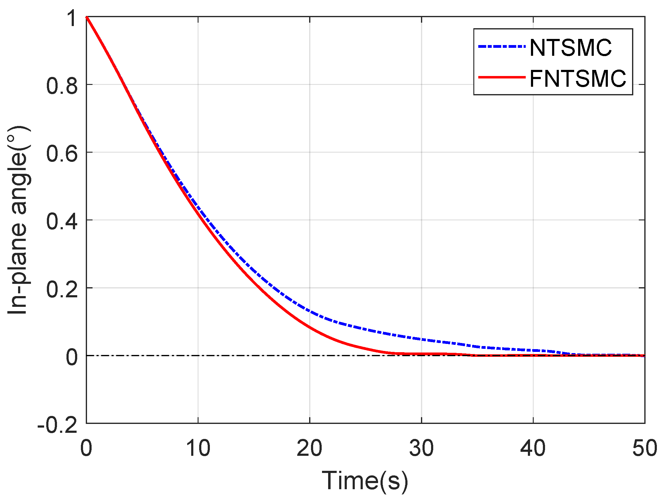
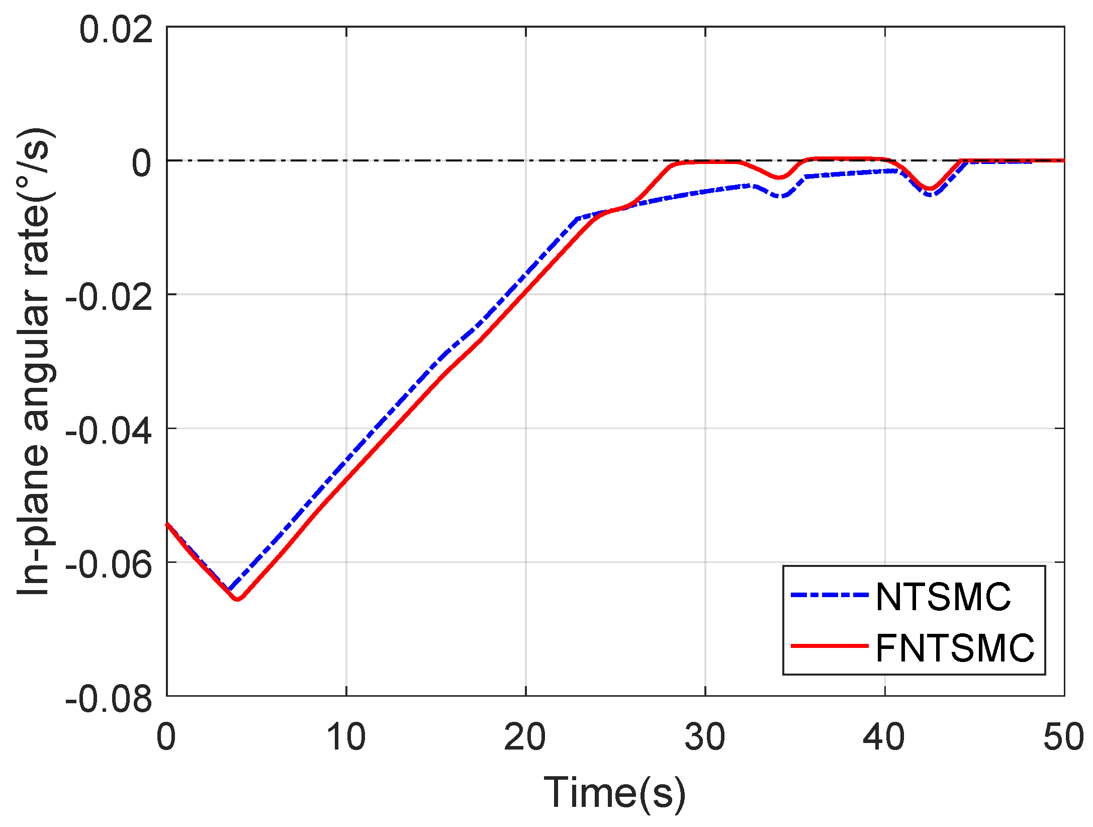
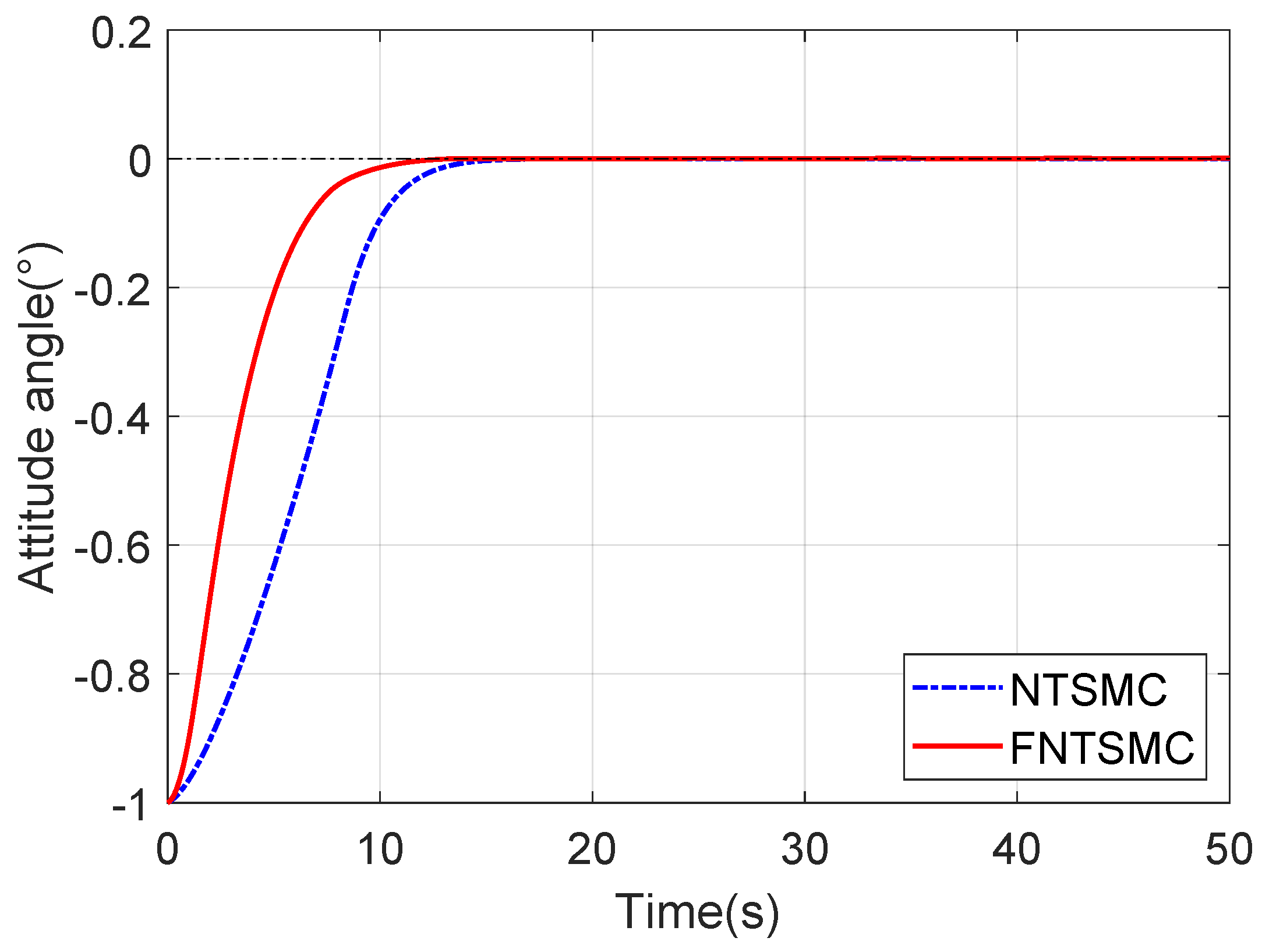
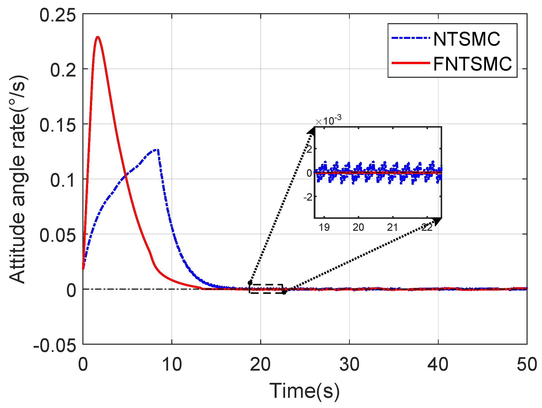
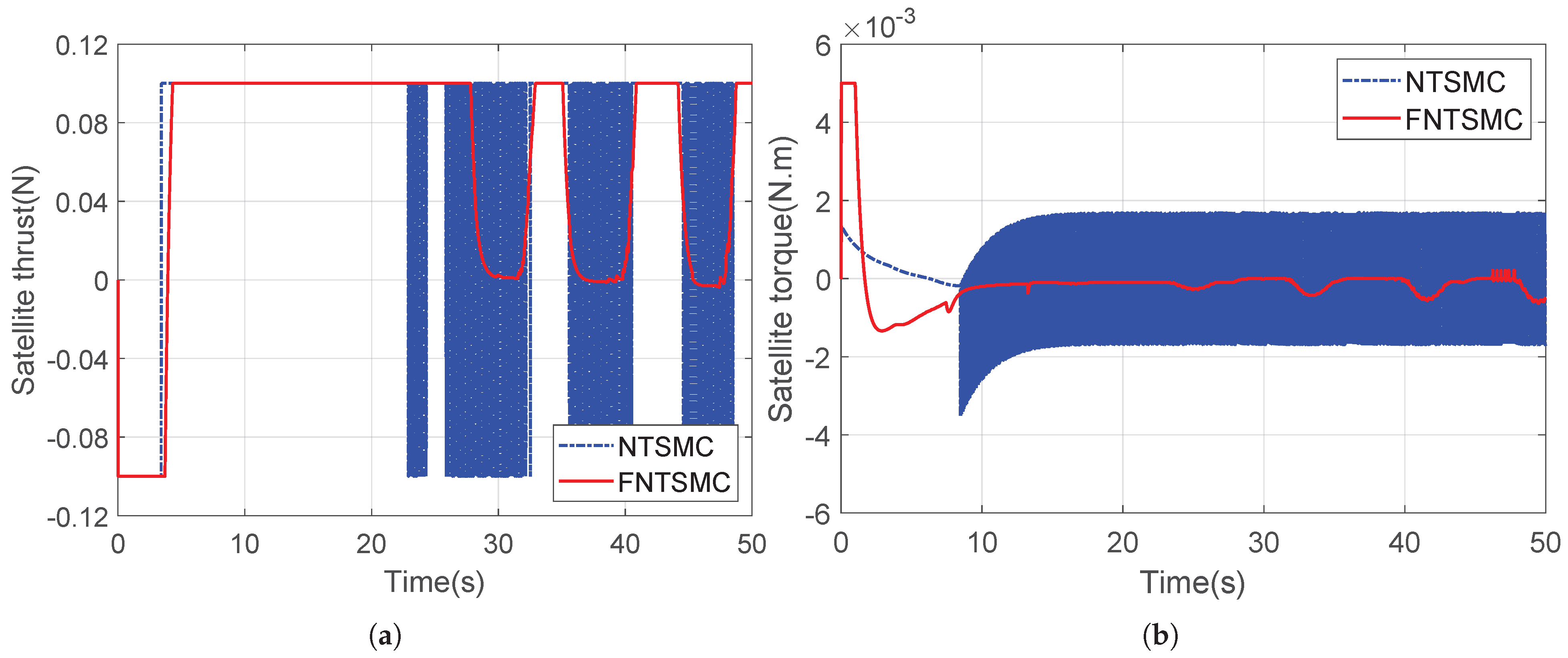
Subsequently, comprehensive comparative simulations were conducted to evaluate the proposed control scheme. These simulations capture the dynamic response of the STS system, including detailed attitude angles and thruster output characteristics. The system’s initial conditions were configured with an in-plane angle of 1 , attitude angle of 1 , and thrust saturation at 0.1 N. The desired reference state for both angles was 0 . The resultant data, presented quantitatively in Figure 3, Figure 4, Figure 5, Figure 6 and Figure 7, provide validation of the controller’s performance. In the figures, FNTSMC denotes the proposed fixed-time nonsingular terminal sliding-mode controller, while NTSMC refers to the conventional benchmark controller employed for comparative analysis.
Figure 3 and Figure 4 present the time histories of the STS system’s in-plane attitude angle and angular rate, respectively. The proposed FNTSMC drives the attitude angle to converge to 0 within approximately 30 s, while the angular velocity converges to 0 around 35 s. This satisfies the control objective within the prescribed timeframe. In contrast, NTSMC requires 50 s to converge both states to equivalent precision, demonstrating a 40 % reduction in convergence time for the proposed controller.
Figure 5 displays the attitude angle response of the STS system. Analysis reveals that while the conventional NTSMC demonstrates fast convergence behavior, the proposed FNTSMC achieves notably superior convergence speed. Specifically, FNTSMC reaches the target attitude ( 0 ) within 12 s, representing a 20 % improvement over the “NTSMC” convergence time. Corresponding results for angular velocity are shown in Figure 6. The convergence characteristics mirror those observed for the attitude angle: FNTSMC achieves stability in 13 s, whereas NTSMC requires 15 s to converge to the steady-state neighborhood. Crucially, the conventional controller exhibits persistent low-amplitude chattering in its steady-state error, as visible in the enlarged area inset. In contrast, the designed FNTSMC maintains smooth output dynamics throughout the operation. This effective chattering suppression is attributed to the piecewise sliding-mode surfaces inherent to the proposed control architecture.
Figure 7a presents the thrust profile of the satellite’s thrusters during the control maneuver. The simulation reveals that during initial attitude correction, thrusters operate at maximum capacity to achieve rapid orientation adjustment. Due to the satellite’s low mass and compact dimensions, significant floating inertia occurs during maneuvering. Consequently, counter-thrusters activate to compensate for this momentum, followed by staged pulse modulation during steady-state maintenance. Crucially, comparative analysis with NTSMC demonstrates FNTSMC’s superior thrust control performance, particularly in vibration suppression during both transient and steady-state phases. The proposed controller achieves smoother thrust transitions and significantly reduced actuator oscillations. Building on the thrust profile analysis, Figure 7b presents the corresponding torque dynamics generated by the thrusters. The FNTSMC demonstrates markedly superior control performance, maintaining consistently lower torque magnitudes throughout the maneuver. This torque reduction stems from the controller’s precise attitude compensation capabilities and optimized thrust modulation. Critical comparative analysis of Figure 7 reveals severe chattering phenomena in the conventional NTSMC implementation for this flexible STS configuration. These high-frequency oscillations induce significant actuator stress on thrusters, accelerating mechanical fatigue and potentially causing mission-critical failures. Consequently, FNTSMC’s chattering suppression capability substantially enhances both operational safety and structural integrity of the STS system.

5. Conclusions

This research has addressed the attitude control challenge for rigid–flexible coupled space tether systems (STSs) through the development of a novel fixed-time nonsingular terminal sliding-mode controller. The controller integrates fixed-time convergence theory with RBF neural network adaptation, establishing two fundamental theoretical advancements. First, the fixed-time framework provides rigorous guarantees for upper bounds to the convergence time, which is essential for mission-critical STS operations in dynamic orbital environments. Second, the RBF neural network actively compensates for unmodeled dynamics and parametric uncertainties inherent in simplified STS models, significantly enhancing control accuracy and disturbance rejection robustness. Formal stability guarantees are established through comprehensive Lyapunov analysis, ensuring theoretical rigor.
Numerical simulations conducted on an established STS dynamic model demonstrate the controller’s superior performance relative to conventional nonsingular terminal sliding-mode control. When applied to two-degree-of-freedom attitude states and thruster dynamics, the proposed FNTSMC achieves a reduction in convergence time and a decrease in steady-state error and effectively suppresses actuator chattering in thrust/torque outputs. These performance characteristics substantially improve actuator longevity and operational safety for long-duration orbital missions, particularly through the elimination of damaging high-frequency oscillations.
While this study establishes foundational control principles using three core state variables, future work should extend this framework to address critical STS complexities: tether deployment/retraction dynamics, full six-degree-of-freedom attitude regulation, and multi-satellite configurations. Such extensions will enable comprehensive STS maneuverability for emerging on-orbit applications, including active debris removal and satellite servicing, advancing the practical implementation of tether-based space systems.

Author Contributions

C.X.: Conceptualization, Data curation, Formal analysis, Writing—review and editing. Q.S.: Software, Formal analysis. H.Z.: Software, Data curation. B.H.: Software, Writing—original draft. Y.W.: Methodology, Funding acquisition. W.Y.: Conceptualization, Methodology, Project administration. X.S.: Methodology, Funding acquisition, Writing—review and editing. All authors have read and agreed to the published version of the manuscript.

Funding

This paper was funded in part by the National Natural Science Foundation of China (62303137, 62473109), in part by the Special funding of the China Postdoctoral Science Foundation (2023TQ0092), in part by the Natural Science Foundation of Sichuan Province (2025ZNSFSC0461), in part by the New Era Heilongjiang Outstanding Master’s and Doctoral Dissertation Foundation (LJYXL2023-029), in part by the Heilongjiang Postdoctoral Science Foundation (LBH-Z20057), and in part by the the Pre-research Task of State Key Laboratory of Robotics and System (HIT) (SKLRS202404B).

Data Availability Statement

The original contributions presented in the study are included in the article.

Conflicts of Interest

The authors declare no conflicts of interest.

References

  1. Huang, P.; Zhang, F.; Chen, L.; Meng, Z.; Zhang, Y.; Liu, Z.; Hu, Y. A Review of Space Tether in New Applications. Nonlinear Dyn. 2018, 94, 1–19. [Google Scholar] [CrossRef]
  2. Ma, Z.; Huang, P.; Ahn, C.K. Learning-Based Control for Deployment of Tethered Space Robot via Sliding Mode and Zero-Sum Game. IEEE Trans. Circuits Syst. II Express Briefs 2022, 69, 1457–1461. [Google Scholar] [CrossRef]
  3. Xu, S.; Wen, H.; Huang, Z.; Jin, D. A Fuzzy Control Scheme for Deployment of Space Tethered System with Tension Constraint. Aerosp. Sci. Technol. 2020, 106, 106143. [Google Scholar] [CrossRef]
  4. Su, B.; Zhang, F.; Huang, P. Stability Research of a Triangular Tethered Satellite Formation: Dynamics, Filtering, and Control. IEEE Trans. Aerosp. Electron. Syst. 2022, 58, 5240–5255. [Google Scholar] [CrossRef]
  5. Yu, B.S.; Dai, P.B. Deployment Dynamics of a Tape-Shaped Tethered Satellite. J. Aerosp. Eng. 2022, 35, 04022044. [Google Scholar] [CrossRef]
  6. Williams, P.; Trivailo, P. Dynamics of Circularly Towed Aerial Cable Systems, Part I: Optimal Configurations and Their Stability. J. Guid. Control. Dyn. 2007, 30, 753–765. [Google Scholar] [CrossRef]
  7. Zhang, Z.; Yu, Z.; Zhang, Q.; Zeng, M.; Li, S. Dynamics and Control of a Tethered Space-Tug System Using Takagi-Sugeno Fuzzy Methods. Aerosp. Sci. Technol. 2019, 87, 289–299. [Google Scholar] [CrossRef]
  8. Tirop, P.; Jingrui, Z. Review of Control Methods and Strategies of Space Tether Satellites. Am. J. Traffic Transp. Eng. 2019, 4, 137. [Google Scholar] [CrossRef]
  9. Kojima, H.; Trivailo, P.M. Model Predictive Tether-Deployment Control for Precise Landing of Tethered Reentry Body. Adv. Space Res. 2019, 64, 1537–1548. [Google Scholar] [CrossRef]
  10. Vafamand, N. Adaptive Robust Neural-Network-Based Backstepping Control of Tethered Satellites with Additive Stochastic Noise. IEEE Trans. Aerosp. Electron. Syst. 2020, 56, 3922–3930. [Google Scholar] [CrossRef]
  11. Zhao, Y.; Huang, P.; Zhang, F. Dynamic Modeling and Super-Twisting Sliding Mode Control for Tethered Space Robot. Acta Astronaut. 2018, 143, 310–321. [Google Scholar] [CrossRef]
  12. Jin, D.P.; Wen, H.; Chen, H. Nonlinear Resonance of a Subsatellite on a Short Constant Tether. Nonlinear Dyn. 2013, 71, 479–488. [Google Scholar] [CrossRef]
  13. Luo, C.; Wen, H.; Jin, D. Deployment of Flexible Space Tether System with Satellite Attitude Stabilization. Acta Astronaut. 2019, 160, 240–250. [Google Scholar] [CrossRef]
  14. Yu, B.; Jin, D.; Wen, H. Analytical Deployment Control Law for a Flexible Tethered Satellite System. Aerosp. Sci. Technol. 2017, 66, 294–303. [Google Scholar] [CrossRef]
  15. Hu, W.; Huai, Y.; Xu, M.; Deng, Z. Coupling Dynamic Characteristics of Simplified Model for Tethered Satellite System. Acta Mech. Sin. 2021, 37, 1245–1254. [Google Scholar] [CrossRef]
  16. Lim, J.; Chung, J. Dynamic Analysis of a Tethered Satellite System for Space Debris Capture. Nonlinear Dyn. 2018, 94, 2391–2408. [Google Scholar] [CrossRef]
  17. Bai, Z.; Jiang, X.; Fu, X. Investigation of the Retrieval Dynamics of the Tethered Satellites Using ANCF-ALE Variable-Length Element. IEEE Trans. Aerosp. Electron. Syst. 2022, 59, 1980–1988. [Google Scholar] [CrossRef]
  18. Kristiansen, K.U.; Palmer, P.L.; Roberts, R.M. Numerical Modelling of Elastic Space Tethers. Celest. Mech. Dyn. Astron. 2012, 113, 235–254. [Google Scholar] [CrossRef]
  19. Li, G.Q.; Zhu, Z.H. Long-Term Dynamic Modeling of Tethered Spacecraft Using Nodal Position Finite Element Method and Symplectic Integration. Celest. Mech. Dyn. Astron. 2015, 123, 363–386. [Google Scholar] [CrossRef]
  20. Gao, F.; Li, J.; Dong, F.; Ji, Y.; Sun, G. Dynamic Modeling and Control Strategy for Tethered Satellite Systems in Orbital Debris Management. Acta Mech. Sin. 2025, 41, 524262. [Google Scholar] [CrossRef]
  21. Zhang, Q.; Zhu, Z.H. Computational Control Framework for Tethered Space Systems Using Finite Element Method. Acta Astronaut. 2025, 228, 595–606. [Google Scholar] [CrossRef]
  22. Ghorbani, H.; Vatankhah, R.; Farid, M. Adaptive Nonsingular Fast Terminal Sliding Mode Controller Design for a Smart Flexible Satellite in General Planar Motion. Aerosp. Sci. Technol. 2021, 119, 107100. [Google Scholar] [CrossRef]
  23. Lu, K.; Xia, Y. Adaptive Attitude Tracking Control for Rigid Spacecraft with Finite-Time Convergence. Automatica 2013, 49, 3591–3599. [Google Scholar] [CrossRef]
  24. Cao, L.; Xiao, B.; Golestani, M. Robust Fixed-Time Attitude Stabilization Control of Flexible Spacecraft with Actuator Uncertainty. Nonlinear Dyn. 2020, 100, 2505–2519. [Google Scholar] [CrossRef]
  25. Tao, X.; Zhang, F.; Huang, B.; Shen, G.; Huang, P. Fixed-Time Sliding Mode Coordinated Deployment Control for Space Triangle Tethered Formation System. IEEE Trans. Aerosp. Electron. Syst. 2024, 60, 1351–1363. [Google Scholar] [CrossRef]
  26. Li, A.-j.; Tian, H.-c.; Wang, C.-q. Fixed-Time Terminal Sliding Mode Control of Spinning Tether System for Artificial Gravity Environment in High Eccentricity Orbit. Acta Astronaut. 2020, 177, 834–841. [Google Scholar] [CrossRef]
  27. Zhang, X.; Wu, F.; Liu, M.; Chen, X. Fractional-Order Robust Fixed-Time Sliding Mode Control for Deployment of Tethered Satellite. Acta Astronaut. 2023, 209, 172–178. [Google Scholar] [CrossRef]
  28. Huang, S.J.; Huang, K.S.; Chiou, K.C. Development and Application of a Novel Radial Basis Function Sliding Mode Controller. Mechatronics 2003, 13, 313–329. [Google Scholar] [CrossRef]
  29. Sun, Y.; Gao, Y.; Zhao, Y.; Liu, Z.; Wang, J.; Kuang, J.; Yan, F.; Liu, J. Neural Network-Based Tracking Control of Uncertain Robotic Systems: Predefined-Time Nonsingular Terminal Sliding-Mode Approach. IEEE Trans. Ind. Electron. 2022, 69, 10510–10520. [Google Scholar] [CrossRef]
  30. Guo, S.; Li, D.; Meng, Y.; Fan, C. Task Space Control of Free-Floating Space Robots Using Constrained Adaptive RBF-NTSM. Sci. China-Technol. Sci. 2014, 57, 828–837. [Google Scholar] [CrossRef]
  31. Li, X.; Sun, G.; Xue, C. Fractional-Order Deployment Control of Space Tethered Satellite via Adaptive Super-Twisting Sliding Mode. Aerosp. Sci. Technol. 2022, 121, 107390. [Google Scholar] [CrossRef]
  32. Zhong, R.; Xu, S. Neural-Network-Based Terminal Sliding-Mode Control for Thrust Regulation of a Tethered Space-Tug. Astrodynamics 2018, 2, 175–185. [Google Scholar] [CrossRef]
  33. Ji, Y.; Xing, Y. A Three-Sub-Step Composite Method for the Analysis of Rigid Body Rotations with Euler Parameters. Nonlinear Dyn. 2023, 111, 14309–14333. [Google Scholar] [CrossRef]
  34. Andrieu, V.; Praly, L.; Astolfi, A. Homogeneous Approximation, Recursive Observer Design, and Output Feedback. SIAM J. Control Optim. 2008, 47, 1814–1850. [Google Scholar] [CrossRef]
  35. Deng, H.; Krstic, M. Output-Feedback Stochastic Nonlinear Stabilization. IEEE Trans. Autom. Control 1999, 44, 328–333. [Google Scholar] [CrossRef]
  36. Tian, B.; Zuo, Z.; Yan, X.; Wang, H. A Fixed-Time Output Feedback Control Scheme for Double Integrator Systems. Automatica 2017, 80, 17–24. [Google Scholar] [CrossRef]
Figure 1. Schematic diagram of STS.
Aerospace 12 00907 g001
Figure 2. Variable definition of simplified STS model.
Aerospace 12 00907 g002
Figure 3. In-plane angle of STS.
Aerospace 12 00907 g003
Figure 4. In-plane angular rate of STS.
Aerospace 12 00907 g004
Figure 5. Attitude angle of STS.
Aerospace 12 00907 g005
Figure 6. Attitude angular rate of STS.
Aerospace 12 00907 g006
Figure 7. Output of the STS Attitude Controller: (a) Thrust of sub-satellite. (b) Torque of sub-satellite.
Aerospace 12 00907 g007
Table 1. Parameters of the STS model.
DescriptionParametersValues
Main satellite mass m m 1000 kg
Sub-satellite mass m s 10 kg
Tether length L 0 100 m
Sub-satellite dimensiona1 m
Table 2. Parameters of the controller.
ParametersValues
K 1 diag ( 0.08 , 0.6 )
K 2 diag ( 0.08 , 0.5 )
K 3 diag ( 0.09 , 0.8 )
ε max 0.0001
p 1 1.1
p 2 [ 0.99 , 0.6 ]
α s [ 1.1 , 1.8 ]
β s [ 0.89 , 0.7 ]
σ ϕ [ 0.01 , 0.001 ]
Disclaimer/Publisher’s Note: The statements, opinions and data contained in all publications are solely those of the individual author(s) and contributor(s) and not of MDPI and/or the editor(s). MDPI and/or the editor(s) disclaim responsibility for any injury to people or property resulting from any ideas, methods, instructions or products referred to in the content.