1. Introduction
In recent years, the observation and modeling of non-cooperative targets have attracted increasing attention. For example, space debris and defunct satellites have attracted increasing attention due to the risks they pose to space operations [
1,
2]. Automated monocular modeling of such targets is fundamental for subsequent tasks such as capture or servicing, yet remains highly challenging under harsh illumination conditions.
Common sensors for modeling include LiDAR, depth cameras, and monocular cameras. While LiDAR systems typically have high power consumption and weight [
3,
4], depth cameras demand intensive computation and face range limitations due to baseline constraints [
5,
6]. By contrast, monocular cameras offer high portability and rich visual information, making them particularly promising for practical applications. However, challenges such as scale ambiguity, complex illumination conditions in space, and significant noise impose stringent demands on monocular vision algorithms.
In some scenarios, prior 3D models of non-cooperative targets are available, such as in maintenance missions involving the Hubble Space Telescope [
7,
8]. Vision-based approaches like PnP solvers and template matching can then be applied by extracting geometric features (points [
9,
10], lines [
11], ellipses [
12]) and establishing 2D–3D correspondences. However, for most non-cooperative targets, prior models are unavailable, and illumination effects, especially in sunlit regions, must be carefully accounted for due to their impact on visual data. As observed in missions such as Hubble servicing and ISS rendezvous, sunlight can cause significant variations across large target surfaces. While no in-orbit monocular modeling of non-cooperative targets has yet been achieved, near-Earth conditions allow the Sun to be reasonably approximated as a parallel light source, which justifies this assumption in our work.
When no prior model exists, visual modeling becomes substantially more challenging. This resembles the classic Simultaneous Localization and Mapping (SLAM) task in robotics [
13]. Feature-based methods (e.g., ORB-SLAM [
14]) and direct methods (e.g., DSO [
15]) are representative approaches, but both rely on the photometric constancy assumption and degrade under significant illumination variations. Recently, AirSLAM [
16] was proposed as an illumination-robust SLAM system that integrates point and line features, demonstrating strong performance under short- and long-term lighting variations.
To mitigate illumination effects in natural scenes, methods such as affine photometric models [
17,
18] and dehazing techniques [
19,
20] have been proposed. However, these mainly address 2D-image processing and do not fundamentally solve intensity variations in space, limiting their effectiveness in harsh space lighting.
SLAM methods are primarily developed for terrestrial environments with relatively stable illumination and modest accuracy demands. In contrast, space missions require greater robustness to illumination changes and higher model precision. Only a few studies have addressed spaceborne non-cooperative targets, and monocular approaches remain scarce. For example, Tweddle proposed an iSAM-based method utilizing stereo depth data [
21]. Zuo et al. introduced a cross-domain pose estimation framework [
22]. Zhang et al. developed an uncertainty-aware monocular pose estimator [
23]. Vincenzo et al. applied optical flow for angular velocity estimation [
24], and Saoji et al. used CNNs to estimate rotation axes [
25]. In addition, a recent factor graph-based active SLAM framework [
26] has been introduced for spacecraft proximity operations, highlighting the growing interest in applying SLAM methodologies directly to space scenarios. While valuable, these methods generally assume favorable lighting and do not explicitly address space illumination effects.
Insights from computer vision and graphics are also relevant. Shape-from-shading and inverse rendering methods attempt to jointly recover lighting, geometry, and material properties from images [
27,
28,
29]. However, they rely on strong assumptions, are sensitive to noise, and are often computationally expensive or require large training datasets, which limits their suitability for real-time space applications.
To overcome these challenges, this paper proposes a hybrid virtual–real framework that integrates photometric compensation, visibility modeling, and dynamic virtual-space feedback for robust monocular modeling of non-cooperative targets. The virtual space provides geometric cues such as surface normals and depth, which are used to refine photometric optimization and improve robustness under complex lighting. The framework is validated on both synthetic and semi-physical platforms.
Compared with existing SLAM-based and inverse-rendering-based approaches, the novelties of this work can be summarized as follows:
- 1.
We propose a hybrid virtual–real framework that integrates rendering-based priors with real monocular observations, enabling dynamic updating of the target model under unknown conditions.
- 2.
An illumination-aware photometric residual is introduced, which explicitly distinguishes self-occluded and shadowed regions, thereby improving pixel selection and ensuring more robust optimization under complex lighting.
- 3.
The framework is validated on both synthetic and semi-physical testbeds, demonstrating improvements in trajectory accuracy, reconstruction quality, and computational efficiency compared with state-of-the-art methods.
The rest of the paper is organized as follows:
Section 2 introduces the preliminaries and problem formulation.
Section 3 presents the proposed hybrid virtual–real framework, including photometric compensation, visibility determination, and virtual space feedback.
Section 4 describes the experimental setup on both simulation and semi-physical platforms.
Section 5 reports the experimental results and analysis. Finally,
Section 6 concludes the paper and discusses future research directions.
2. Overview of the Virtual–Real Fusion Method
Without loss of generality, the following assumptions have been made:
The sunlight is modeled as parallel rays with a constant direction within the mission execution region. This assumption reflects common lighting conditions in space near stars and is widely adopted in space environment modeling.
The direction of sunlight relative to the camera coordinate system is known, and the camera orientation is controllable. This information can be obtained via onboard attitude sensors or sun sensors.
External forces acting on the non-cooperative target are negligible. Most non-cooperative targets are defunct or decommissioned objects, typically in a microgravity environment, and are thus assumed to be free-floating.
Only the first-order reflection of sunlight on the target surface is considered. Since the scene includes only the observing spacecraft and the target, the dominant light entering the camera is the direct reflection from the target surface. Higher-order reflections, whether on the target itself or between the target and the observing spacecraft, are negligible.
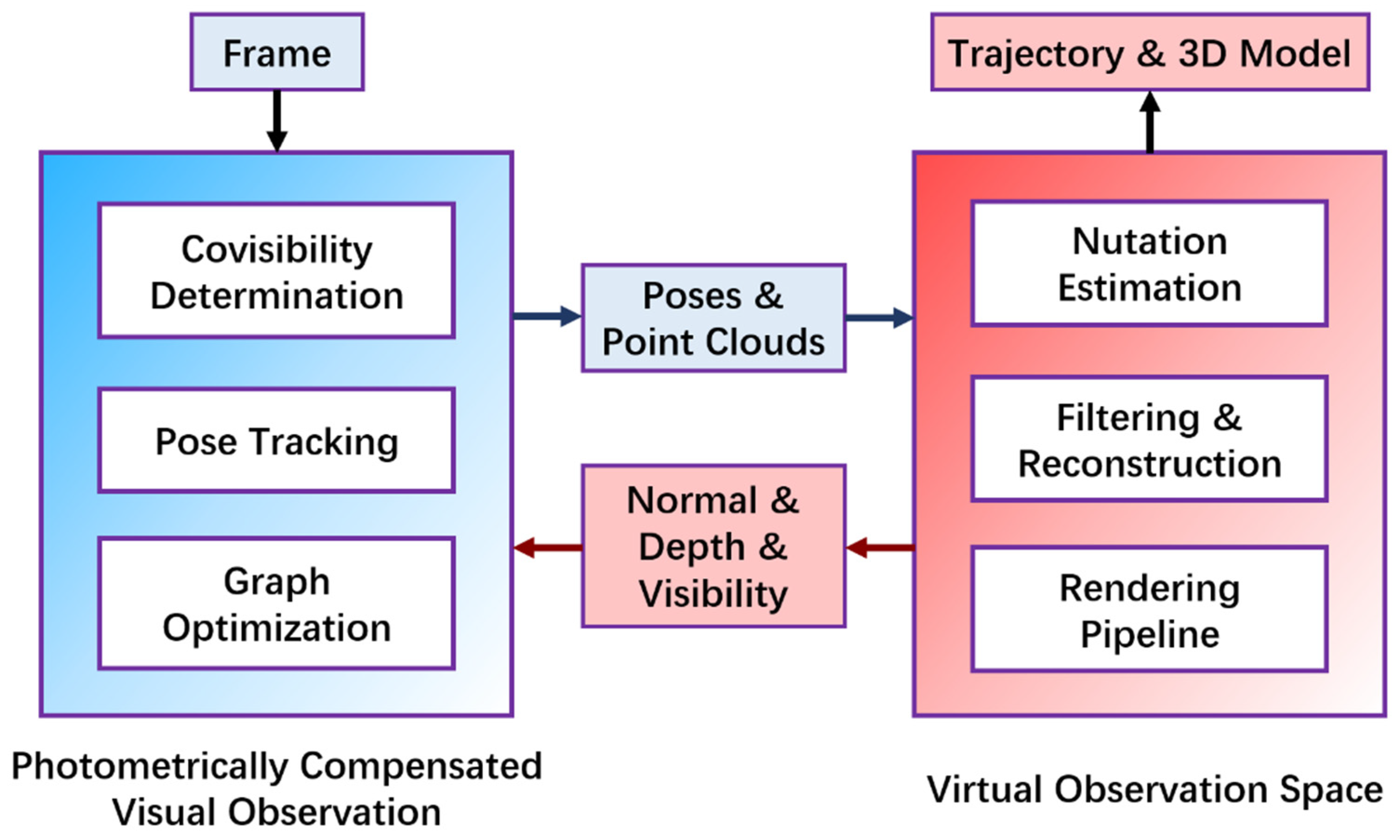
Based on the above assumptions, this paper proposes a novel hybrid approach that integrates real and virtual observations. The overall framework is illustrated in
Figure 1. The left part of the framework is based on photometric compensation, which considers illumination variations on the target surface relative to its pose and accounts for self-occlusion effects. Built upon a direct SLAM framework, this component efficiently and effectively performs localization and mapping, outputting the real-time relative camera pose and a point cloud of the target.
Photometric compensation information is derived from the virtual observation space on the right side of the framework. In this virtual space, the target undergoes torque-free rotational motion (i.e., nutation), with fixed camera pose and solar illumination direction. First, the nutation parameters are optimized in real time using the estimated poses. Then, noise in the point cloud is filtered, and a continuous surface model of the target is reconstructed via Poisson surface reconstruction. Finally, rendering techniques generate illumination information on the target surface, which supports subsequent tracking, optimization, and photometric compensation tasks.
3. Photometric-Compensation-Based Visual Observation and Modeling
3.1. Novel Photometric Model
Existing direct SLAM methods typically rely on the photometric constancy assumption, which states that the pixel intensity of a 3D point remains consistent across different images. To account for illumination variation, we introduce a photometric compensation equation based on the Blinn–Phong illumination model from computer graphics.
The Blinn–Phong model is a classical illumination model in computer graphics [
30]. It consists of three components: ambient reflection (the
term), diffuse reflection (the
term), and specular reflection (the
term). Here,
denotes the unit vector in the direction opposite to sunlight (i.e., the incident light direction), which is treated as a constant.
represents the unit surface normal vector at the target corresponding to pixel
in frame
.
denotes the specular exponent, which controls the shininess of the surface in the specular reflection component. It is a widely used empirical model, which is computationally efficient.
This model is employed to approximate the influence of lighting on pixel intensity to some extent. However, since the model still deviates from actual light reflection in real scenes, a scalar correction factor is introduced, which is constant across the image. Specifically, the modeled illumination is scaled by and subtracted from the observed pixel intensity. This process is referred to as photometric compensation, under the assumption that, after compensation, the pixel intensity corresponding to a given 3D point remains consistent across images (referred as , ). Without this factor (i.e., setting = 1), the residual formulation would degenerate, as the diffuse term computed from pixel intensities would cancel out in Equation (1), leading to an ill-posed pose estimation problem.
In practice, the constant ambient term in the illumination model can be omitted, as it does not affect optimization. Moreover, it is observed that the specular component’s contribution to compensation is marginal. Therefore, only the diffuse reflection term is retained for photometric compensation. The simplified compensation model is given by:
The photometric residual function is defined as:
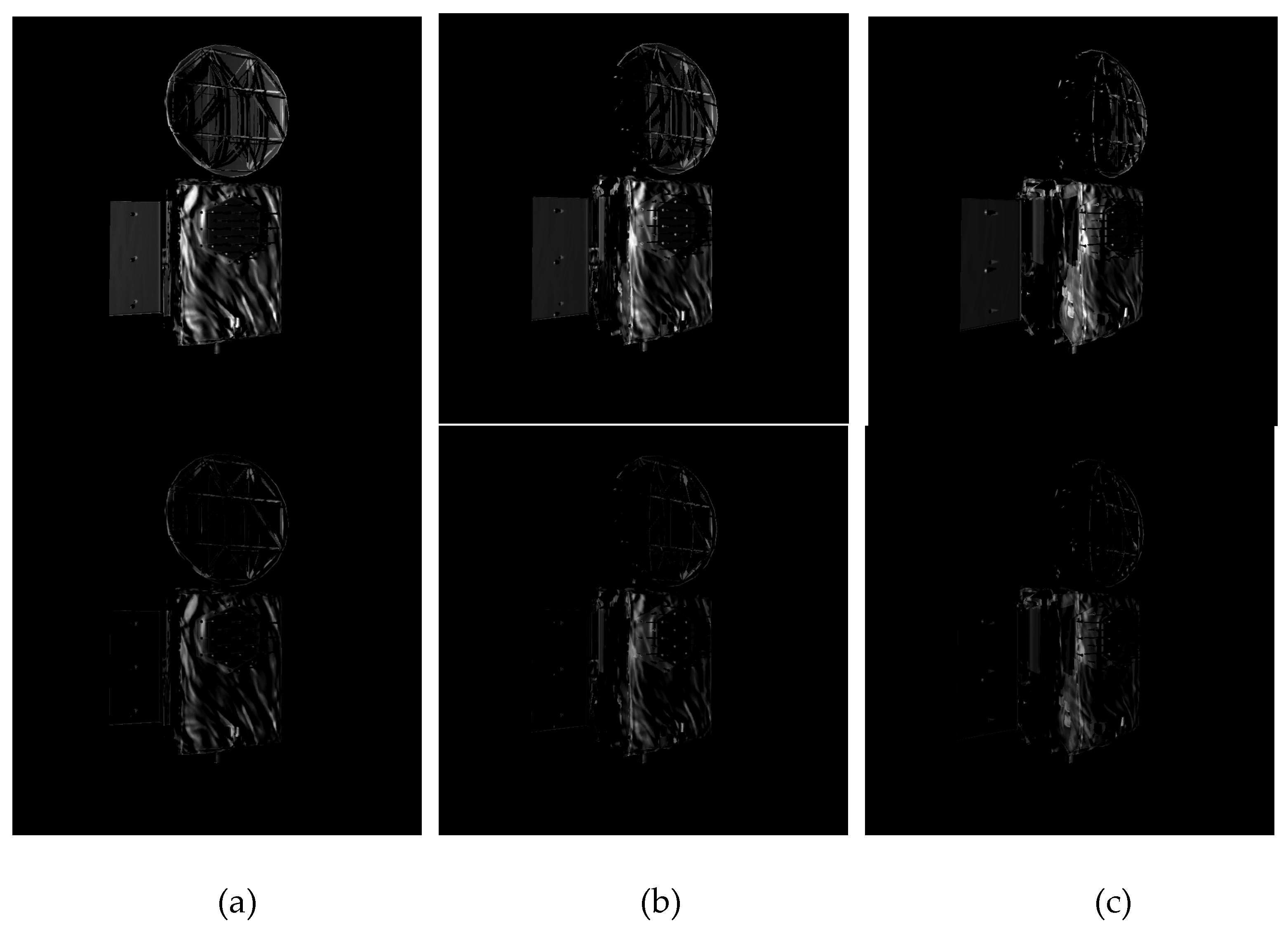
Figure 2 and
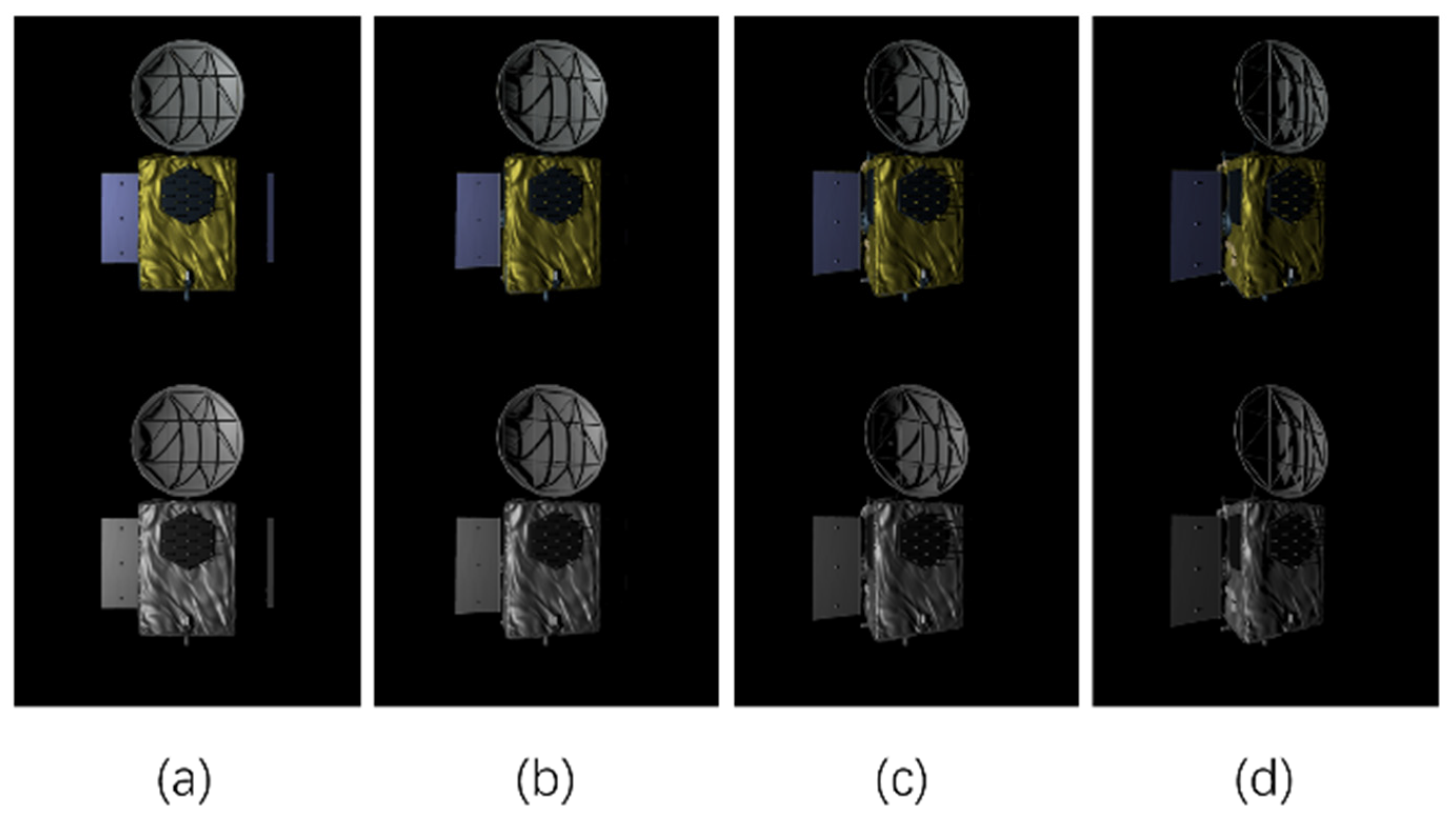
Figure 3 illustrate the residuals of the target image under parallel lighting, computed using the proposed illumination model. It can be seen that, with properly tuned parameters, the photometric residuals are smaller than those obtained under the brightness constancy assumption. Here the angle between the illumination direction and the camera viewing axis is 45°. The images are rendered in Unity3D 2019, with the target object rotated by 15°, 30°, and 45°, respectively.
, is estimated by dividing the pixel intensity by the corresponding diffuse shading term for each frame, then averaging the results across two frames. This estimation strategy is applied consistently throughout the system.
3.2. Cost Functions and Jacobian Functions
Equation (3) is applied throughout the entire system, including geometry initialization (camera and point tracking), local windowed photometric bundle adjustment (PBA), and map reuse. For each point
, the sum of square intensity differences
is calculated over a small patch
around it, comparing the host frame
and the target frame
. The observation of a point in a frame is coded by:
Here, represents a combination of a robust influence function and a gradient-dependent weight, similar to those used in other direct SLAM systems. This function depends on geometric parameters, including frame poses and points’ depth .
When optimizing multiple images jointly in PBA, the objective function is formulated as:
where
is the set of points in
and
is the set of observations for point
. Equations (4) and (5) are minimized using the iteratively re-weighted Levenberg–Marquardt algorithm. Starting from an initial estimate
, which includes poses of related frames and depths of points, each iteration
computes weights
and photometric residuals to estimate an increment
by minimizing a second-order approximation of Equation (5) with fixed weights:
Here,
and
is a diagonal matrix with the weights
,
is the residual error vector. The Jacobian matrix
consists of
, which represents the Jacobian of the error
with respect to a left-composed increment, expressed as:
Let
denote the Jacobian matrix of the conventional photometric error, which is widely known and used. The Jacobian matrix of our error is derived as follows:
The scalar correction factor thus prevents degeneration of the residual and stabilizes optimization, ensuring that inter-frame alignment remains valid. Its value is determined empirically based on experimental observations.
3.3. Inverse Compositional Algorithm
Due to computational constraints, it is not feasible to optimize all frames in real time. As in many existing methods, keyframes at intervals are selected and extract pixels from them for optimization. In the back-end, multiple relevant keyframes and their associated pixel depths are jointly optimized by minimizing Equation (5). The sparsity of the Hessian matrix is exploited to improve computational efficiency during the optimization.
In the front-end, each new frame is matched against the latest keyframe, and the camera pose is estimated using the Lucas–Kanade method by minimizing Equation (4). However, recomputing the Jacobian matrix at each iteration is computationally expensive. To address this, the inverse compositional algorithm proposed by Simon Baker and Iain Matthews [
31] reverses the roles of the template and target frames. In this formulation, the Jacobian matrix is computed only once for the keyframe and reused to estimate the pose update, which is then applied inversely to the target frame. This significantly reduces the computational cost. They further proved that under the brightness constancy assumption, this approach is mathematically equivalent to the original Lucas–Kanade method. Whether a similar approach remains valid under our photometric compensation model requires further justification.
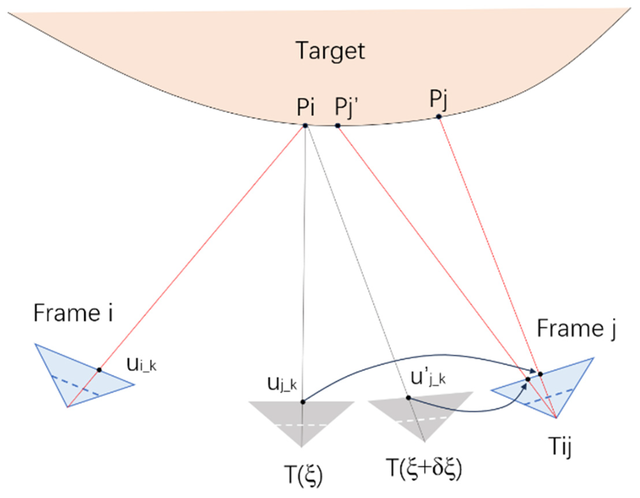
Figure 4 illustrates the front-end image matching process, where Frame
i serves as the template frame and Frame
j is the target frame whose pose is to be estimated. A 3D point
projects to pixel
in Frame
i. Given a current pose estimate
, the point projects to
in Frame
j, and after one iteration update to
, it projects to a new position
.
In the original Lucas–Kanade method, Jacobian matrices must be computed with respect to and in Frame j at every iteration. In contrast, the inverse compositional method computes the Jacobian only once at in the template frame, thereby reducing the computational cost.
Under the photometric compensation model, Frame i uses the surface normal of point pᵢ, while Frame j should use the surface normal of or . It is important to note that some implementations may still choose to use , but in such cases, the inverse compositional method becomes inapplicable. A brief justification is provided below.
Let the mapping from
to
be denoted as
When Frame
i is used as the template, the cost function becomes:
The compensation term here follows Equation (1). The continuous version of Equation (10) is:
It is rewritten in compositional form:
Assuming
, Equation (12) transforms into:
If the current estimation
is approximately correct, we can ignore the first-order terms in the derivative and the variation in the integration area. Equation (13) then simplifies to:
The simplification requires that the compensation term use the surface normal at point , not at . The discrete form of Equation (14) corresponds to the cost function of inverse compositional method. Hence, the inverse compositional method can be adapted to our photometric error model.
3.4. Visibility Determination
In addition to photometric compensation, it is also necessary to determine the visibility of spatial points during modeling. Visibility directly affects the estimation of both camera poses and pixel depths, and it is also essential for assessing correlations between keyframes in back-end optimization.
In conventional visual SLAM systems, a 3D point is considered visible as long as it projects into the camera’s field of view at a given pose. However, in single-object scenarios, many points are subject to self-occlusion. For a surface point to be truly visible, it must not only fall within the camera’s view but also be illuminated by sunlight. Points located on the backside of the object or within self-cast shadows should be regarded as invisible. In implementation, this visibility check is realized by verifying that a point’s depth corresponds to the nearest surface along the camera ray and that its surface normal is oriented toward the camera.
By leveraging the virtual space, we can obtain surface normals, depth values, and shadow information for each pixel in a keyframe. These factors are then jointly used to determine the visibility of a 3D point. Based on this visibility analysis, the number of co-visible points between different keyframes can be computed, which in turn informs the selection of keyframe to be included in back-end optimization. The detailed process of extracting pixel-level information from the virtual space will be described in the next section.
4. Uncooperative Target Virtual Space
This section describes the algorithmic components of the virtual space for noncooperative targets, including 3D model construction, the rendering pipeline, and nutation parameter optimization. The input data consist of point cloud coordinates and camera trajectories estimated during the modeling stage. The outputs include per-pixel surface normals, depth values, visibility masks, and visualized results, which serve as inputs for subsequent modeling algorithms.
4.1. Modeling from Point Clouds
The visual modeling process yields an unordered and noisy point cloud. The Point Cloud Library (PCL) is employed to reconstruct a 3D model through the following steps:
Outlier Removal: A radius-based outlier removal algorithm is applied to eliminate isolated noise points, thereby enhancing the robustness of subsequent reconstruction stages.
Normal Estimation: Surface normals are estimated for each point using the NormalEstimationOMP algorithm, which leverages OpenMP for parallel acceleration. A k-nearest neighbors (KNN) search is performed, and the target center is set as a fixed viewpoint to ensure outward-facing normals.
Surface Reconstruction: A continuous surface mesh is generated via the Poisson reconstruction algorithm. An octree depth is specified to control reconstruction resolution. The resulting triangle mesh, which is then cropped using the bounding box of the input point cloud to eliminate redundant regions.
Drift Removal: To mitigate surface drift artifacts introduced during reconstruction, each triangle’s vertices is examined using a KNN search. Triangles whose vertices lie too far from the original point cloud are discarded, thereby improving model accuracy.
Post-processing and Visualization: Colors and surface normals are interpolated for the remaining mesh vertices, and the final reconstructed model is visualized.
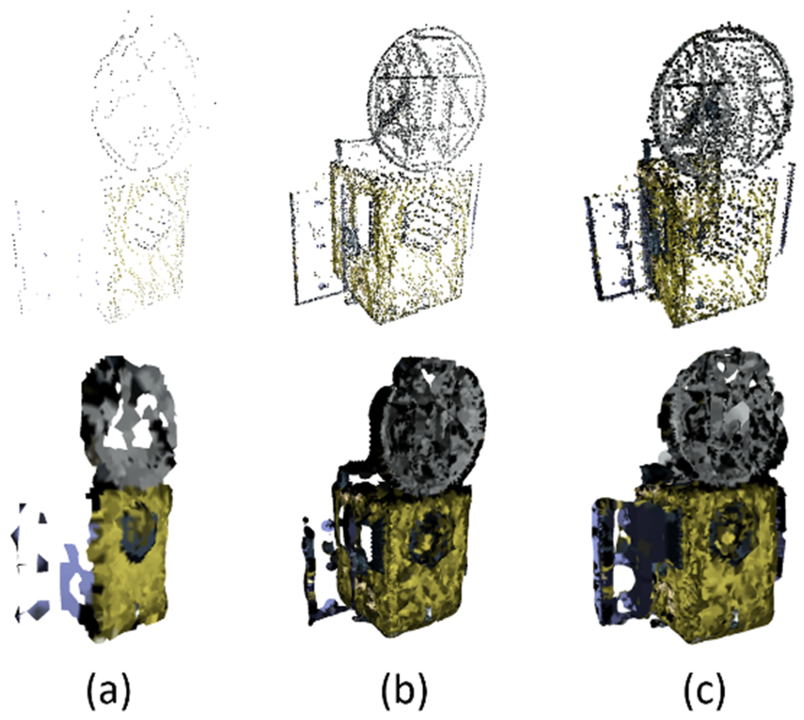
Figure 5 illustrates the 3D reconstruction results at different time steps. The top row shows the raw point clouds, while the bottom row presents the corresponding Poisson-reconstructed surface models. As the camera progressively observes more surface regions, the number of points increases and the reconstructed model becomes more complete.
As shown in
Figure 2, the thin plate exhibits low pixel gradients. Consequently, the associated pixels are not excluded from optimization candidate selection, which inevitably leads to holes in the reconstructed model. This, in turn, may compromise the accuracy of visibility determination in those regions.
4.2. Model Data Extraction Based on Rendering
Following the principles of the overall system, once the 3D model has been constructed, the virtual space must output per-pixel depth, surface normal, and visibility information from the camera’s perspective. Rendering techniques provide an efficient and GPU-accelerated solution to this task. OpenGL is employed to implement two classic rasterization-based rendering pipelines: one for extracting depth and normal information, and the other for computing visibility.
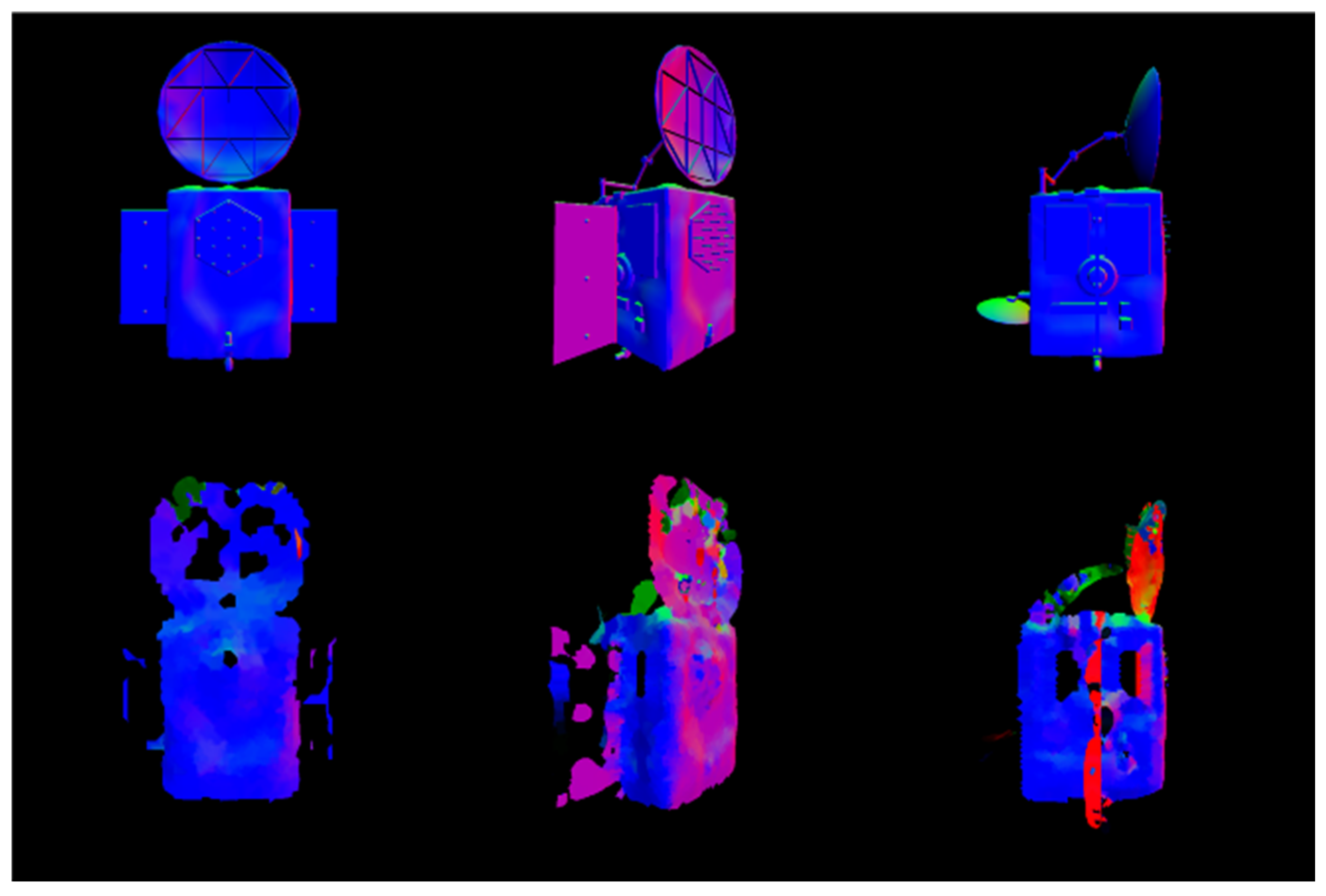
Given the 3D model and camera poses, the rasterization pipeline comprises the following stages: model transformation, view transformation, projection transformation, rasterization, Z-buffer testing, and fragment shading. In the first pipeline, the surface normal of each visible pixel is used as the shading output and written to the framebuffer. The corresponding depth and normal information is then retrieved from the framebuffer and depth buffer using the glReadPixels function.
Figure 6 shows an example of the output surface normal maps.
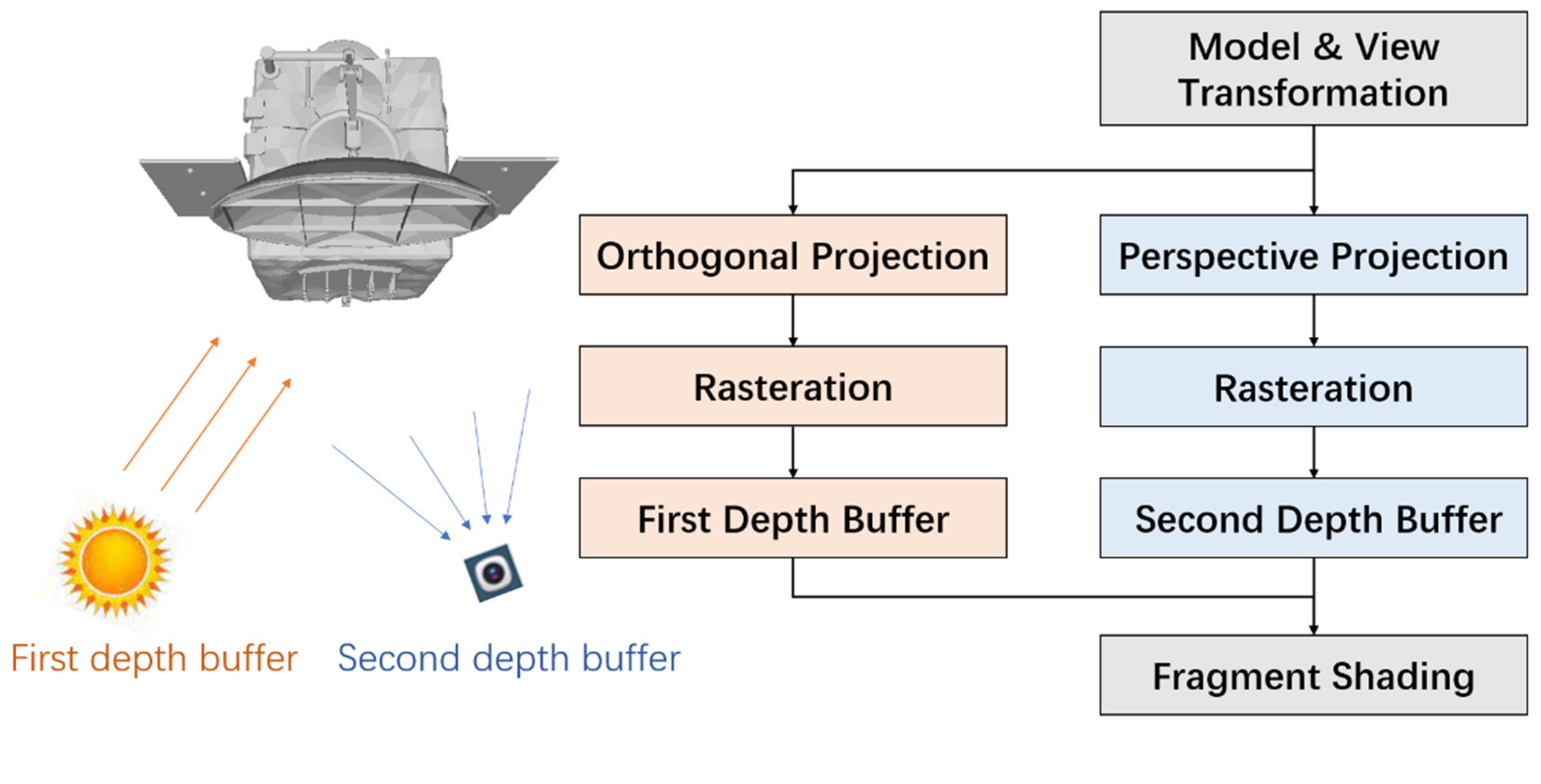
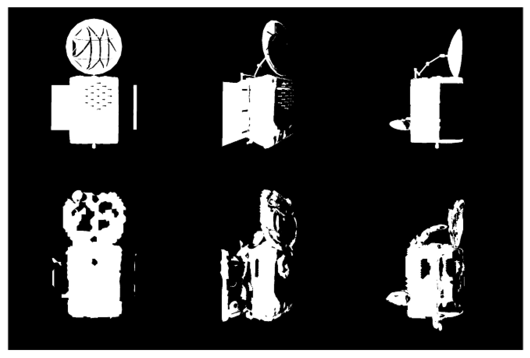
To determine pixel-level visibility, both illumination coverage and camera view coverage must be considered. To this end, the basic rendering pipeline is extended by introducing a lighting-related auxiliary pass. In this pass, orthographic projection is used to simulate directional light (i.e., sunlight), and the depth of the nearest surface point is recorded in a dedicated shadow depth buffer. This depth information is passed to the main rendering pass, where it is compared against the actual depth values to determine whether a pixel is illuminated. A pixel is considered visible only if it is both within the camera’s field of view and directly illuminated by sunlight. In the visibility output, visible pixels are rendered in white, while occluded or out-of-sight pixels are rendered in black.
Figure 7 illustrates the visibility determination pipeline.
Figure 8 shows the visibility maps generated at various time steps.
4.3. Motion Parameter Optimization
According to [
32], the motion of an uncooperative space target without propulsion follows either uniform rotation or precession. The precession angle is determined by the target’s inertia distribution, while the angular velocity is governed by the initial momentum. During precession, the magnitude of the angular velocity remains constant, and its direction rotates uniformly around the target’s momentum axis (the
z-axis in
Figure 9). In our virtual space, the instantaneous angular velocity of the target is computed and fitted to a conical trajectory. This fitted trajectory is subsequently used to refine camera pose estimations, providing a more physically consistent motion prior for subsequent modeling steps.
4.4. Implementation Details
The entire system is implemented in C++, with several engineering considerations addressed to improve performance and accuracy:
Vectorized Computation: To improve computational efficiency, vectorized computation (SSE) is used when calculating image errors and Jacobians, enabling parallel operations.
High-Precision Normal Output: Off-screen rendering with a floating-point framebuffer is adopted to extract per-pixel normal vectors more accurately, avoiding quantization errors from standard 8-bit outputs.
Coordinate System Transformations: Appropriate coordinate transformations are performed to ensure consistency across different libraries (OpenCV, OpenGL, PCL).
Depth Conversion: Depth values from the rendering pipeline are converted back to true depths for use in photometric computation and visibility analysis.
5. Experiment Results and Discussion
This section presents the experimental results together with corresponding discussion. In addition to reporting trajectory accuracy and 3D reconstruction quality, we analyze the influence of illumination conditions, evaluate computational efficiency, and compare the proposed framework with existing methods. The discussion also highlights the implications of these results for spaceborne applications and identifies potential limitations of the current study.
To evaluate the effectiveness of the proposed algorithm, a series of experiments is conducted. As there is currently no publicly available dataset specifically designed for non-cooperative target observation, we built two custom platforms to generate experimental data: a Unity3D-based simulation platform and a semi-physical experimental platform. Image sequences collected from these platforms were used to compute and analyze camera trajectory and 3D reconstruction errors.
5.1. Unity3D Simulation Platform
A synthetic simulation environment is developed using Unity3D, into which we imported a textured satellite model. The satellite was set to rotate at a constant angular velocity of 18°/s to simulate self-rotation. A physical camera with specified intrinsic parameters was used to capture the rendered scenes. To assess the effect of lighting, we configured the light direction at different angles relative to the camera view direction, generating four sets of rendered image sequences. Representative frames from these sequences are shown in
Figure 2.
5.2. Semi-Physical Simulation Platform
To more accurately reflect real-world conditions, a semi-physical simulation platform is built based on a mobile robotic system. In this setup:
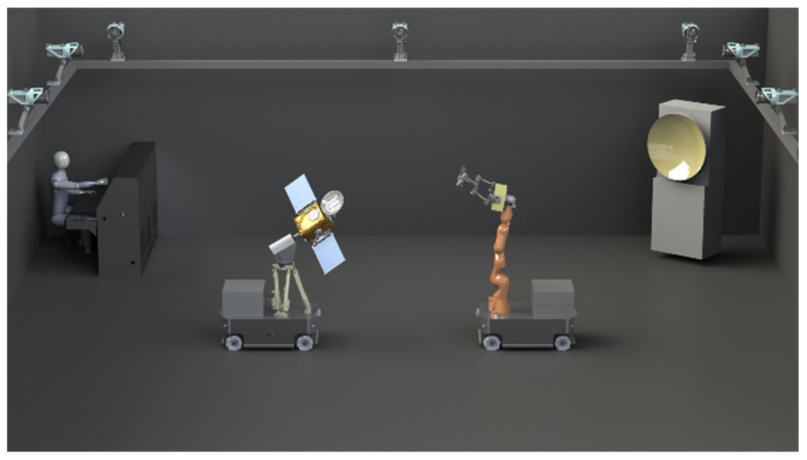
A mobile parallel mechanism simulates the tumbling motion of a non-cooperative target.
A robotic manipulator carries a mock satellite, mimicking the observation process.
A sunlight simulator provides a collimated light beam with a 1 m diameter to replicate solar illumination.
The pose of the robot’s end-effector is measured and controlled via a motion capture system to ensure precise ground-truth reference.
Additional implementation details can be found in [
33].
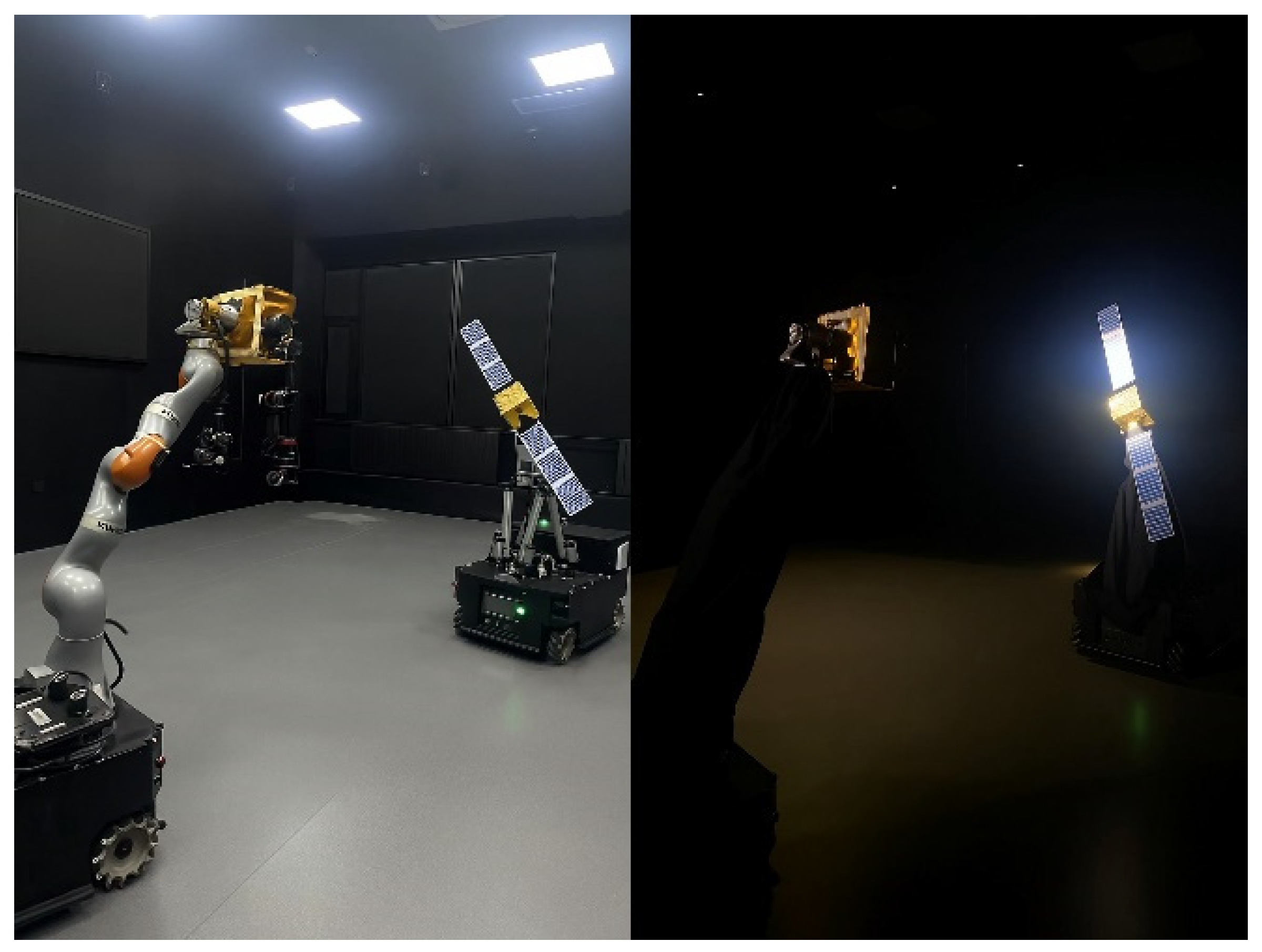
The overall hardware schematic and a photograph of the experimental setup are shown in
Figure 10 and
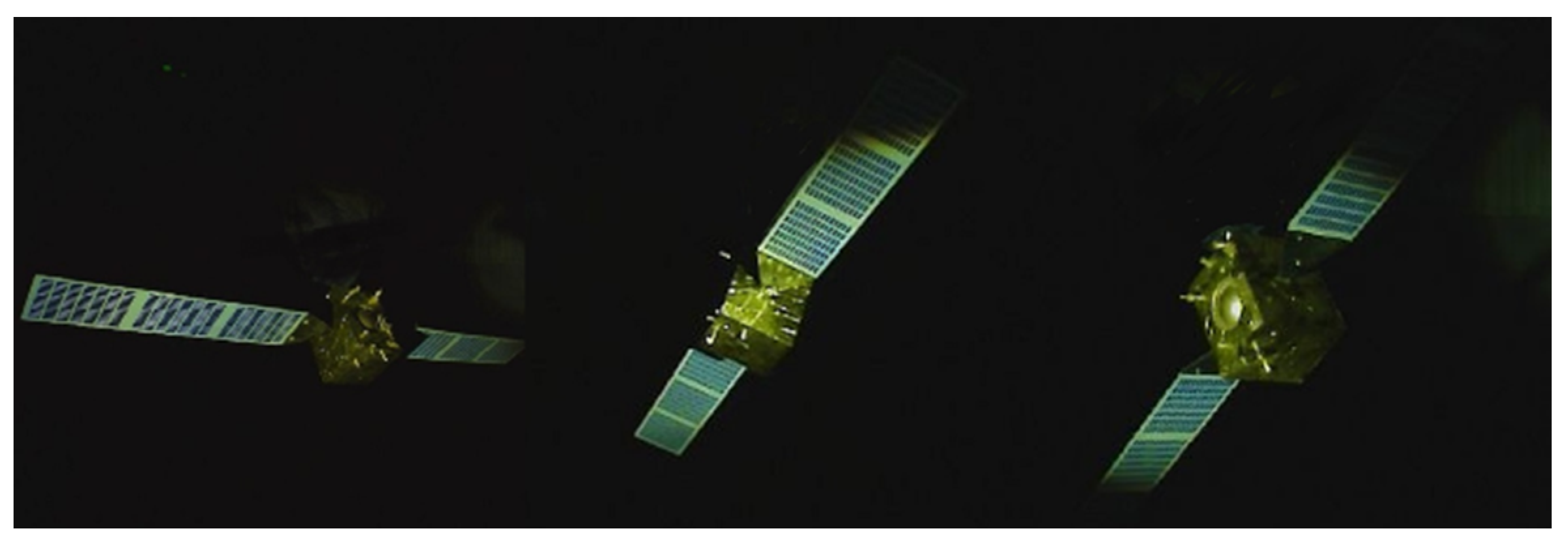
Figure 11, respectively. Sample images captured during the experiments are presented in
Figure 12.
5.3. Experimental Procedure and Results
In the experiments, the Unity3D simulation platform is used to generate four sets of image sequences, where the target underwent self-rotation at a constant angular velocity of 18°/s. Additionally, four more sets of sequences were collected using the semi-physical simulation platform, where the target exhibited tumbling motion characterized by a nutation angle of 10°, with both nutation and spin angular velocities set to 9°/s. The camera operated at 30 frames per second, and all images had a resolution of 720 × 720 pixels.
The experiments were conducted on a workstation running Ubuntu 20.04, equipped with 32 GB RAM, an Intel i9-12900 CPU, and an NVIDIA RTX 3060 Ti GPU.
Given that our method follows the principles and optimization strategies of direct methods, its computational efficiency is comparable to conventional direct SLAM systems. The front-end tracking takes approximately 5 ms per frame, while back-end optimization is triggered upon insertion of a new keyframe—on average, one every five frames—with each optimization step requiring about 250 ms. According to our calculations, without the inverse compositional method described in
Section 3.3, the tracking time per frame would increase to 12 ms due to the additional image Jacobian computations. The computational cost of the algorithm is mainly determined by the number of selected corner points and the number of optimization iterations, with both factors being approximately proportional to the total runtime. In addition, GPU acceleration is utilized for both virtual space rendering and data extraction, achieving an average processing time of 5 ms per frame.
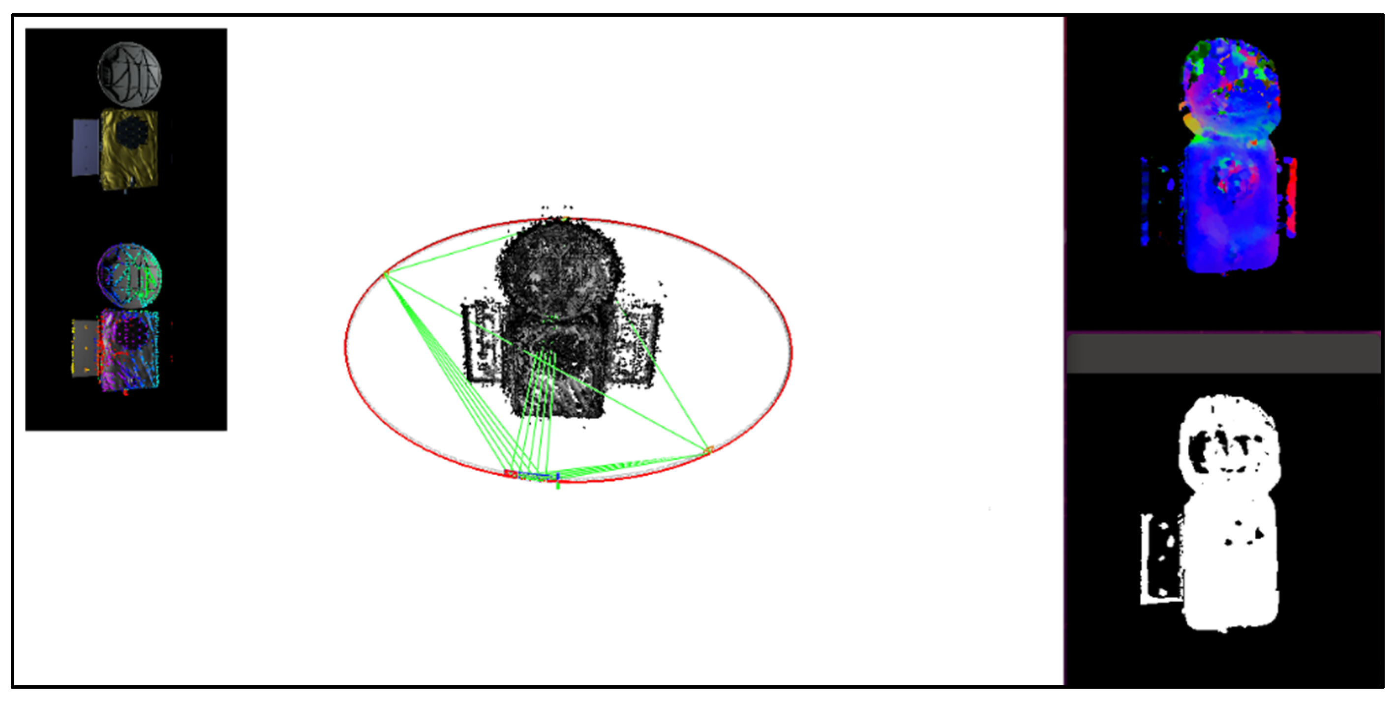
Figure 13 shows the algorithm’s visualization interface. The left panel displays the implementation of photometric compensation, while the right panel presents the real-time outputs from the virtual space.
The performance of four SLAM pipelines is evaluated:
In our implementation, the compensation constant in Equation (1) was empirically set to 0.15.
We report both trajectory estimation error and point cloud reconstruction error. Since monocular SLAM inherently suffers from scale ambiguity, both the estimated trajectories and reconstructed models were aligned to ground truth via similarity transformation (i.e., translation and scale alignment). Notably, due to the circular or spiral nature of camera motion, full rotation alignment was avoided to prevent misleading results. All error values are reported in normalized units, where the camera-to-object center distance is set to 1.
As shown in
Table 1, the proposed method consistently achieves the lowest errors across all tested scenarios, including both synthetic and semi-physical setups. As the illumination angle increases, the errors for all methods generally increase. Notably, feature-based methods and direct methods with global photometric optimization tend to fail beyond 30° illumination, indicating poor robustness under severe lighting variation.
In contrast, our method demonstrates high resilience to illumination changes by jointly considering lighting-aware visibility estimation and per-pixel compensation. Approximately 40% of low-visibility pixels are automatically excluded from keyframe correlation checks, significantly improving robustness and reducing reconstruction noise.
6. Conclusions
In this work, a hybrid virtual–real framework is proposed for the observation and modeling of non-cooperative space targets, combining illumination compensation with a point cloud-based virtual space. The system provides geometric cues such as surface normals and pixel visibility, which are fed back into the photometric optimization to improve robustness and accuracy. Experiments on both simulated and semi-physical platforms demonstrate that the proposed method achieves superior trajectory estimation accuracy and 3D reconstruction quality under challenging illumination.
Overall, this work represents the first monocular framework that explicitly incorporates illumination effects into virtual–real modeling of non-cooperative space targets, offering improved robustness compared with existing SLAM-based approaches.
It should be noted that the validation has been conducted using Unity3D-based simulations and a semi-physical platform. While these environments allow evaluation under diverse and challenging illumination conditions, the absence of real in-orbit mission data limits the external validity of the results. Moreover, the current framework relies on simplified illumination and reflectance assumptions, which may restrict its applicability to more complex environments or highly reflective targets.
Future research will therefore explore broader applicability by testing across diverse target types, including large and irregularly shaped spacecraft. Integration with deep learning techniques also offers promising directions: for example, learning-based modules for photometric compensation, shadow detection, or pose initialization could be incorporated to improve generalization and adaptability. These directions will enhance the scalability of the approach and facilitate its application to real-world space missions. In addition, while camera parameters were assumed accurate in simulations and calibrated in the semi-physical setup, unique sensor errors may occur in real space missions; future in-orbit experiments will be required to validate and further improve the robustness of the proposed framework under such conditions.
