Article

Towards a Balanced Design of a Grid Fin with Lightweight Aerodynamics and Structural Integrity

Key Laboratory of Pressure Systems and Safety, Ministry of Education, School of Mechanical and Power Engineering, East China University of Science and Technology, Shanghai 200237, China
*
Author to whom correspondence should be addressed.
Aerospace 2025, 12(10), 899; https://doi.org/10.3390/aerospace12100899
Submission received: 22 August 2025 / Revised: 1 October 2025 / Accepted: 3 October 2025 / Published: 5 October 2025
(This article belongs to the Section Aeronautics)

Abstract

It is widely accepted that the lightweight design of a grid fin is closely related to its aerodynamic performance and structural integrity, while limited work seeks their balance. This study proposes a lightweight grid fin design method by taking the locally swept-back angle as a variable based on three-dimensional computational fluid dynamics and fluid–thermo–structure coupling analysis for Mach numbers ranging from 0.8 to 5. The effect of the swept-back angle on the relative aerodynamic efficiency profit, weight saving, and structural integrity (with a focus on static strength) was analyzed. The results showed that the locally swept-back configuration maintained structural integrity while enabling simultaneous aerodynamic performance improvement and weight saving across different Mach numbers through swept-back angle adjustment. At Mach 0.8, 1.5, and 2.0, the 20° swept-back configuration achieved a 13.2% weight saving and improved aerodynamic performance. At Mach 0.9, the 15° configuration delivered optimal aerodynamic enhancement with a 10% weight saving. Notably, the 15° configuration demonstrated excellent balance after evaluating all Mach number operating conditions. All these highlight a good attempt for the trade-off design of structures among weight saving, aerodynamic performance, and structural integrity.

1. Introduction

An extreme lightweight design is a key driving force for aerospace vehicles to achieve cost control and efficient payload transportation [1]. The grid fin is a highly efficient aerodynamic control device, consisting of an external support frame and an internal grid of intersecting small chord surfaces that enable the precise attitude control and trajectory adjustment of aerospace vehicles [2,3]. Due to its special polyhedral structure, the grid fin exhibits excellent aerodynamic performance compared with the traditional planar fin, such as greater resistance to forces, lower hinged moment, higher stall angle, and better foldability [4,5], making it widely used in various types of aerospace vehicles [6,7,8]. The lightweight design of a grid fin can enhance the effective payload, reduce launch costs, optimize fuel efficiency, and improve the flight maneuverability, thereby driving the development of aerospace vehicles towards low-cost and large-scale production.
Aerodynamic performance is a crucial factor in the lightweight design of grid fins, determining their functionality and efficiency. When achieving the weight savings of grid fins through structural design, the change in structure will exert a direct influence on aerodynamic performance by affecting the airflow characteristics over the grid fin surface, thus altering key aerodynamic parameters such as drag and lift. Currently, numerous studies focus on the influence of structural design parameters on the aerodynamic performance of grid fins. Miller and Washington [9] conducted wind tunnel tests to investigate the effects of the outer frame cross-section shape and web thickness on aerodynamic performance within a Mach number range of 0.5 to 2.5, indicating that these parameters exerted a notable influence on drag. Tripathi et al. [10,11,12] conducted subsonic wind tunnel tests to systematically investigate the correlation between the aerodynamic characteristics of a grid fin and key design parameters such as grid configuration, gap-to-chord ratio, and aspect ratio, demonstrating that optimizing these design parameters could enhance the aerodynamic efficiency and improve stalling characteristics. In addition, based on numerous viscous computational fluid dynamics simulations, it was found that changing the rectangular cross-section to an NACA 0012 symmetrical airfoil resulted in an average reduction of about 27% in drag [13]. Dinh et al. [14] designed three grid fin models with different grid patterns, and the simulation results of their aerodynamic characteristics underscored the hexagonal grid pattern’s superiority. Zeng et al. [15,16,17] and Debiasi et al. [18,19] experimentally and numerically verified the effectiveness of the split swept-back grid fin (specifically referring to the entire grid frame swept-back along the chord direction) and its combination with a sharp leading edge under both transonic and lower supersonic regimes, reducing drag by about 12~13% and 30%, respectively. In the higher supersonic regime, Schülein and Guyot [20,21] drew inspiration from delta wings to propose a locally swept-back configuration for grid fins, where the leading edge of each individual cell was swept. The experimental results demonstrated that this design reduced the total drag at zero lift by 30% to 40%. Yadav et al. [22,23] studied the aerodynamic performance of a locally swept-back cascade fin at subsonic speed by numerical simulation. The results indicated that the lift and drag were reduced, and the drag reduction was large, which increased the average aerodynamic efficiency by 12.09%. In addition, the aerodynamic characteristics of isolated grid fins with four different internal grid patterns were computed, and the advantages and applicable scope of each grid pattern were systematically analyzed. Lee [24] evaluated the influence of the number of grid fin cells on aerodynamic performance through wind tunnel tests under transonic conditions. The results indicated that increasing the number of cells enhanced lift but also exacerbated drag and shock wave interactions, reflecting an inherent design trade-off between lift and drag.
It appears that current studies on the structural design of grid fins, though limited in scope, mainly focus on the influence of key geometric parameters (such as fin thickness, cross-sectional shape, grid pattern, number of grid cells, etc.) on lift, drag, and other aerodynamic characteristics. However, with the rapid development of high-performance aerospace vehicles, an extremely light structural weight has emerged as an increasingly critical design challenge. Notably, changes in structural weight not only directly affect the aerodynamic performance but also have an impact on structural integrity. Excessive or insufficient structural weight may subject the structure to varying degrees of challenges when bearing external loads, compromising its stability and reliability. Therefore, in lightweight design, these three factors—structural weight, aerodynamic performance, and structural integrity—should be considered comprehensively.
This study aims to propose an improved lightweight method for grid fins by employing a locally swept-back configuration, which can achieve a balance among weight saving, aerodynamic performance, and structural integrity by adjusting the locally swept-back angle. First, the computational fluid dynamics method was validated using experimental data. Then, taking an unswept grid fin as the baseline configuration, numerical simulations were performed to investigate the aerodynamic characteristics of grid fins with different locally swept-back angles across a Mach number range of 0.8 to 5, covering subsonic, transonic, and supersonic regimes, with a focus on variations in lift, drag, and the lift-to-drag ratio. Furthermore, the fluid–thermo–structure coupling method was employed to analyze the structural response of the grid fins under aerodynamic loads, focusing on the stress and displacement distribution to evaluate the structural integrity. All results were compared with those of the baseline configuration to evaluate the effectiveness of the locally swept-back configuration in balancing a light weight, aerodynamics, and structural integrity.

2. Numerical Modeling Approach

2.1. Geometry Model

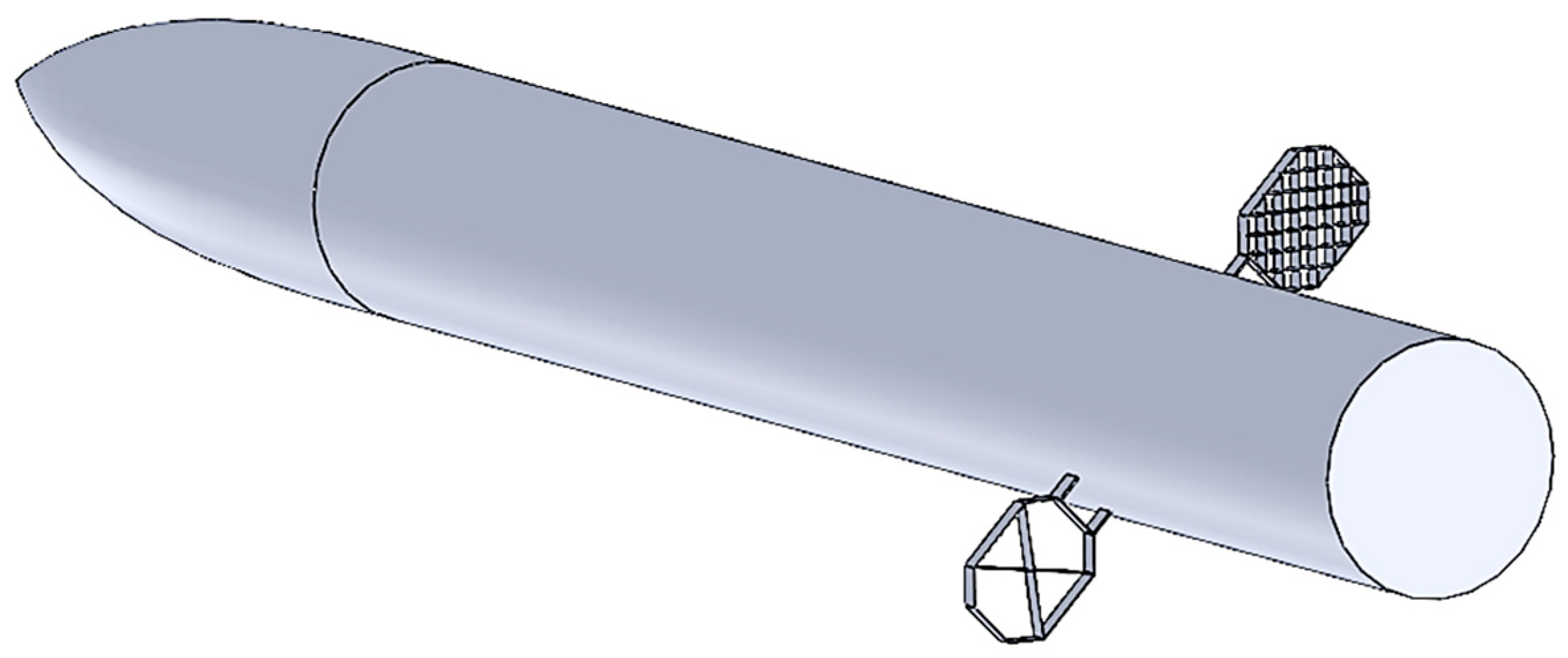
An improved lightweight design method was proposed based on the existing locally swept-back configuration. Although the existing locally swept-back configuration (Figure 1b) had the aerodynamic advantage of drag reduction, it failed to achieve weight saving due to the constraint of maintaining the same surface area as the baseline grid fin (Figure 1a). Therefore, it would be interesting to check the effectiveness of the locally swept-back configuration in weight saving.
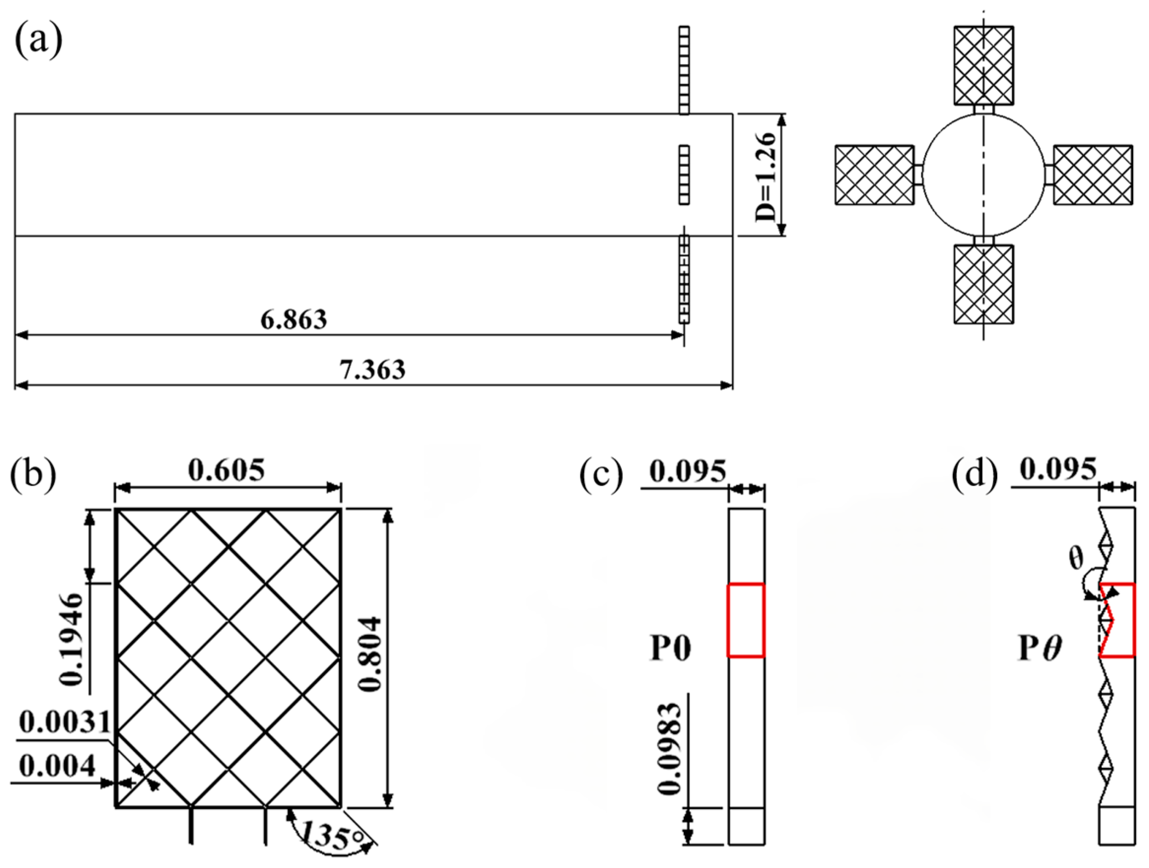
The first sub-stage model used in this study is shown in Figure 2a. It consists of a 7.363 m long and 1.26 m diameter body of revolution, with four grid fins mounted on the body 0.5 m in front of the base in a cruciform shape. The baseline and the locally swept-back grid fins have the same internal grid and size parameters. The front view is shown in Figure 2b, in which the span is 0.605 m, the height is 0.804 m, the grid spacing is 0.1946 m, the outer frame thickness is 0.004 m, the inner frame thickness is 0.0031 m, and the chord length is 0.095 m.
The side view of the baseline grid fin (P0) is shown in Figure 2c, where the outer frame of the grid cell is rectangular. The lightweight locally swept-back grid fin is formed by sweeping back the leading edge center of each grid cell in the baseline grid fin along the chord length direction, with its outer frame shown in Figure 2d. The locally swept-back angle (θ) serves as a key design variable for controlling the weight saving effect. In this study, the θ was set as 5°, 10°, 15°, and 20°. Note that due to symmetry, only half of the rocket first sub-stages were selected as the computational domain (Figure 3).

2.2. Numerical Method

In the case of a simultaneous calculation of aerodynamic force, aerodynamic heat, and structural deformation, the computational cost of the fluid–thermo–structure coupling simulation will be extremely high [25]. In the present study, to reduce costs, a partition coupling method based on computational fluid dynamics (CFD) was adopted to solve the aero-thermoelastic problem. This method effectively balances computational accuracy and efficiency by using an independent computational framework of existing CFD solvers and structural analysis tools [26].
The numerical simulation of the three-dimensional steady compressible flow field is conducted based on the Reynolds-Averaged Navier–Stokes (RANS) method. Under low hypersonic conditions (Ma < 7), the effects of real gas are negligible [27]. Therefore, the ideal gas assumption is adopted in this study, and kinetic viscosity (μ) is calculated based on the Sutherland law. The expression is as follows [14]:
μ = μ 0 T / T 0 3 / 2 T 0 + S T + S
where T and T0 are the static and the reference temperature, respectively, μ0 is the kinetic viscosity at T0, and S is the Sutherland constant.
The SST k-ω model was used to simulate the turbulent flow, which combined the good performance of the k-ω model in near-wall flow and the advantages of the k-ε model in a freestream, and predicted flow separation close to the boundary layer more accurately.
Based on ANSYS 22.1.0 Fluent, the flow variables (such as turbulent viscosity) were solved by a second-order upwind discretization scheme. The least squares cell-based reconstruction method was employed to compute the gradients at cell centers.
The analysis of aero-thermoelastic problems relies on flow field calculations. On this basis, the influence of aerodynamic heat on the structural thermal response can be obtained by solving the heat conduction equation. The three-dimensional solid heat conduction equation is as follows:
ρ C p T t = x λ T x + y λ T y + y λ T y
where ρ denotes the density of solid materials, Cp represents the specific heat, and λ is the thermal conductivity.
According to the theory of elasticity mechanics, the total strain of a structure consists of elastic strain and thermal strain. For an isotropic solid material, the total strain tensor can be expressed as
ε i j = ε i j e + ε i j T ε i j e = 1 E 1 + ν σ i j ν σ k k δ i j ε i j T = α Δ T δ i j
where ε i j e and ε i j T , respectively, represent the elastic strain tensor and the thermal strain tensor, E is the elastic modulus, ν represents Poisson’s ratio, σ i j is the stress tensor, σ k k is the trace of the stress tensor, δ i j is the Kronecker delta, and α is the linear expansion coefficient.

2.3. Computational Mesh

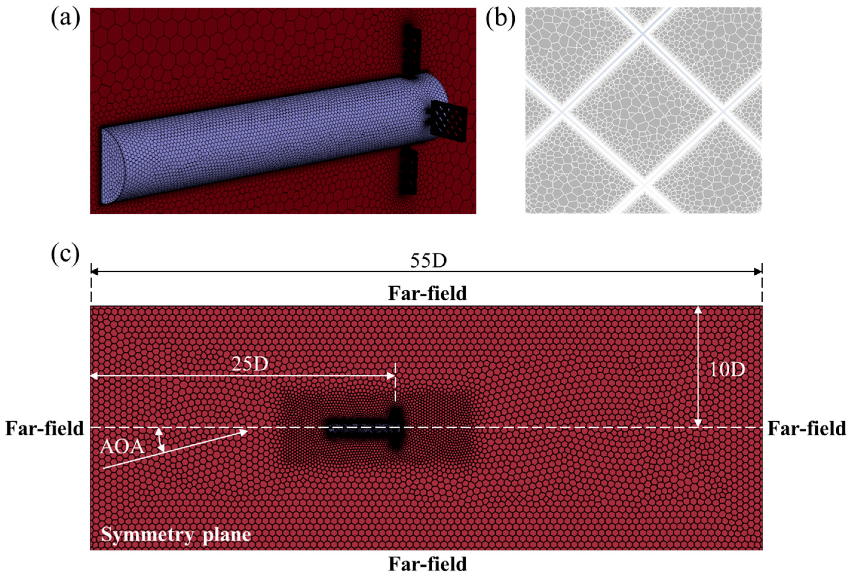
Generating high-quality computational meshes represents the most significant challenge in simulating the flow field around the first sub-stage with grid fins using CFD methods. The grid fins have a complex geometry, especially the locally swept-back configuration with sharp leading edges. In order to adapt to these complex features, the quality of a structured grid is difficult to guarantee, and the generation of the grid will consume a large number of computational resources. Thus, in this study, the Fluent Meshing tool was used to generate the unstructured polyhedral mesh. In the polyhedral volume fill approach, multiple tetrahedral cells are combined to form a polyhedral cell, which reduces the overall cell count. This mesh has strong flexibility and adaptability with complex geometries and high computational efficiency, and can predict the gradient calculation and local flow conditions more accurately, demonstrating outstanding advantages in simulations.
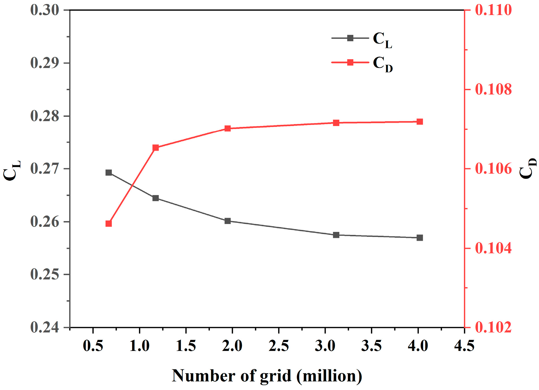
As shown in Figure 4, the polyhedral cells were applied in the flow field domain away from the wall. The prismatic cells were generated near the body and grid fin surfaces to resolve near-wall flow phenomena. The first cell spacing of the near-wall grid was 5 × 10⁻⁵ m, and the growth factor was 1.2. Also, a refinement region with a uniform cell size was added in the vicinity of the entire model region to improve the computational accuracy. Five sets of meshes from sparse to dense (0.669, 1.17, 1.95, 3.12, and 4.02 million cells) were generated to verify the grid independence test. The detailed results of this test will be presented and discussed in Section 3.1. The meshing strategy was applied to the locally swept-back models so as to generate the grids corresponding to them.

2.4. Boundary Conditions

Figure 4c illustrates the computational domain and boundary conditions, employing a cylindrical domain measuring 55D in length and 10D in radius. Here, D denotes the diameter of the first sub-stage body, as shown in Figure 2a. The outer boundary was set with far-field pressure boundary conditions, while the symmetric surface adopted symmetric conditions, and all solid surfaces were assigned nonslip conditions. The freestream parameters were set as follows: Mach number in the range of 0.8 to 5 (specifically taking the values of 0.8, 0.9, 1.2, 1.5, 2, 3, 4, and 5), static pressure at 5466.5 Pa, static temperature at 216.65 K, and angle of attack (AOA) at 10°. The reference area was taken as the cross-sectional area of the body, which measures 1.2469 m2, while the reference length was specified as the diameter of the body, at 1.26 m. In the structural analysis, the results of the pressure and temperature calculated from the CFD simulation were used as the loads. The grid fin is made of GH4169, a nickel-based superalloy that is widely used, and the material properties are presented in Table 1.

3. Results and Discussion

3.1. Grid Independence Test

To examine how the mesh quantity affects the results, the lift coefficient (CL) and drag coefficient (CD) of the baseline configuration at Mach 0.8 were adopted as reference indices to validate grid independence. As shown in Figure 5, five sets of meshes from sparse to dense were tested.
The test results indicate that with the refinement of the mesh, the values of the CL and CD gradually tend to stabilize. Once the mesh is refined to 3.12 million cells, the lift and drag coefficients are almost stable, and the curves tend to smooth. Compared with the mesh number of 4.02 million, the CL only changes by 0.20%, and the CD deviates by 0.03%, suggesting that the grid-independent state has been reached. To ensure calculation accuracy while enhancing efficiency, the mesh with 3.12 million cells was chosen as the mesh in all calculations.

3.2. Computational Fluid Dynamics Validation

The steady numerical method was verified using wind tunnel test data for grid fins provided by Washington and Miller [28]. The wind tunnel model contains two grid fin configurations, namely, the fine mesh grid fin and the “X” pattern grid fin, as shown in Figure 6. The geometry model is illustrated in Figure 7, where two grid fins are symmetrically mounted on both sides of the missile body.
Based on the RANS equations solver and the meshing strategy in Section 2.3, simulations were conducted on the static normal force coefficients (CN) of two grid fins mounted on a missile body at varying angles of attack under Mach numbers 0.8, 1.1, and 2.5, with the results presented in Figure 8. It is evident that the simulated data are highly consistent with the experimental data both in terms of numerical values and variation trends. The maximum errors between the simulated and experimental data of the fine mesh grid fin and the “X” pattern grid fin are 6.24% and 5.22% at Mach 0.8, 1.91% and 7.75% at Mach 1.1, and 3.96% and 14.89% at Mach 2.5, respectively. This indicates that the numerical method and meshing strategy used are feasible and provide a reliable accuracy for the flow field calculations of the grid fin.

3.3. Effects of θ on Aerodynamic Coefficients

Aerodynamic performances between the baseline grid fin and those that were locally swept-back were compared under Mach numbers ranging from 0.8 to 5, employing nondimensional parameters such as the lift coefficient (CL), drag coefficient (CD), and lift-to-drag ratio (CL/CD).
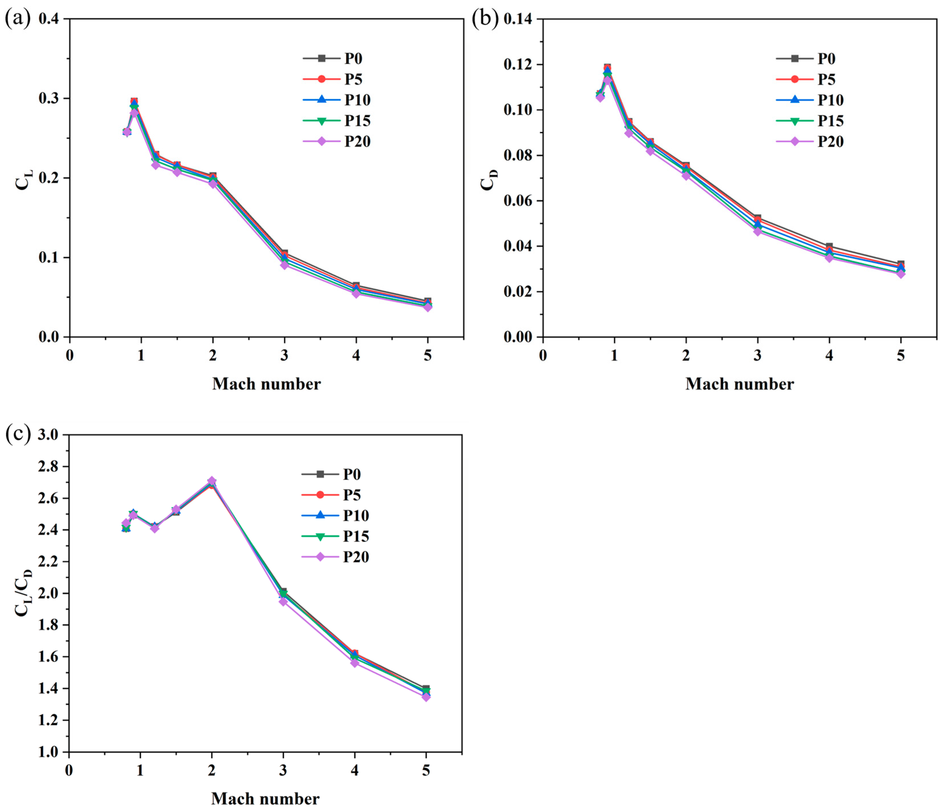
Figure 9a shows the variation of CL with the Mach number across different locally swept-back angles (θ). For all grid fins, CL increases with the increase in the freestream velocity and reaches its maximum at Mach 0.9, after which it begins to decrease. Notably, within the subsonic regime, lift characteristics display a high degree of similarity. As for the transonic and supersonic regimes, the CL of the locally swept-back configuration registers a slightly lower value compared with that of the baseline. Moreover, at the same Mach number, an increasing θ leads to the decrease in CL.
The literature [29] shows that Mach 0.9, within the transonic range, has emerged as a key research focus due to the occurrence of maximum drag forces. Similarly, the maximum CD for all fins occurs at Mach 0.9 (Figure 9b), a finding that corresponds to the flow choking phenomenon within grid cells under transonic conditions. It is worth noting that the drag of the locally swept-back configuration is lower than that of the baseline across all Mach conditions investigated. Additionally, the degree of drag reduction exhibits an increasing trend with the increase in θ, and this reduction is particularly obvious at higher supersonic speeds.
Referred to as aerodynamic efficiency, the lift-to-drag ratio (CL/CD) constitutes a crucial aerodynamic parameter, as it is relevant to both the aerodynamic performance assessment and the selection of structural design parameters for the grid fin. Overall, the CL/CD demonstrates a characteristic trend of initial increase followed by subsequent decrease with rising Mach number (Figure 9c). When the Mach number is less than 2, the locally swept-back configuration typically has a higher CL/CD than the baseline. When the Mach number exceeds 2, the former is lower than the latter. However, there is no obvious linear relationship between the aerodynamic efficiency and the locally swept-back angle.
To quantify the aerodynamic performance improvement of the locally swept-back configuration relative to the baseline after weight saving, the relative aerodynamic efficiency profit (denoted as RPθ) is calculated based on the baseline grid fin’s CL/CD as follows:
R P θ = C L / C D θ C L / C D 0 / C L / C D 0 × 100 %
Table 2 shows RPθ across the whole Mach range investigated, where positive values signify improved performance and negative values signify reduced performance. The improvement of aerodynamic performance varies at each Mach number. For Mach numbers of 0.8, 1.5, and 2.0, the aerodynamic performance of the grid fin with θ = 20° experiences the most significant improvement. Specifically, the RPθ values are 1.49%, 0.71%, and 0.94%, respectively. When the Mach number is 0.9, the grid fin with θ = 15° demonstrates the most substantial improvement in aerodynamic performance, with the RPθ value being 0.34%. When the Mach numbers are 1.2, 3.0, 4.0, and 5.0, the aerodynamic performance of the locally swept-back configuration exhibits a decrease, and the specific parameters are not listed one by one. In reality, during the recovery process of flying objects, the grid fin is unlikely to encounter merely a single Mach number but instead is confronted with multiple flight stages including supersonic, transonic, and subsonic phases, so RPθ values are further averaged according to the Mach number to calculate the averaged RPθ (RPθavg). According to the RPθavg value in Table 2, the θ leads to a reduction in the aerodynamic performance of the grid fin, but the reduction range is only within 1.04%.
RPθavg is a single measure of aerodynamic performance, without considering the factor of weight saving, and thus the comprehensive optimal value of θ cannot be determined. As shown in Table 2, while the RPθavg values are identical at θ = 5° and θ = 15°, the latter offers superior weight saving, leading to a better comprehensive performance at θ = 15°. However, RPθavg is ineffective for comparing θ = 15° and θ = 20°, as the latter, despite having the highest aerodynamic performance loss, also yields the greatest weight saving, highlighting the trade-off between aerodynamic performance and weight saving. To determine the overall optimal θ value for balancing aerodynamic performance and weight saving objects, the aerodynamic loss–weight saving ratio (LWθavg) parameter was defined, which is the ratio of the average relative aerodynamic efficiency loss (RPθavg) to weight saving (WSθ). This is calculated by using Equations (5) and (6).
L W θ avg = R P θ avg W S θ × 100 %
W S θ = W 0 W θ / W 0 × 100 %
where W0 and Wθ are the weights of the baseline and locally swept-back grid fins, respectively, at a specific θ. θ is the design variable that controls the weight saving effect of the grid fin, with a larger value leading to a greater weight saving, as shown in Figure 2d. Therefore, WSθ approximately increases linearly with θ, as shown in Table 3. When θ = 15°, LWθavg reaches its minimum value. This result indicates that at this value, it is possible to achieve the maximum possible weight saving while effectively maintaining its aerodynamic performance.

3.4. Effects of θ on Flow Characteristics

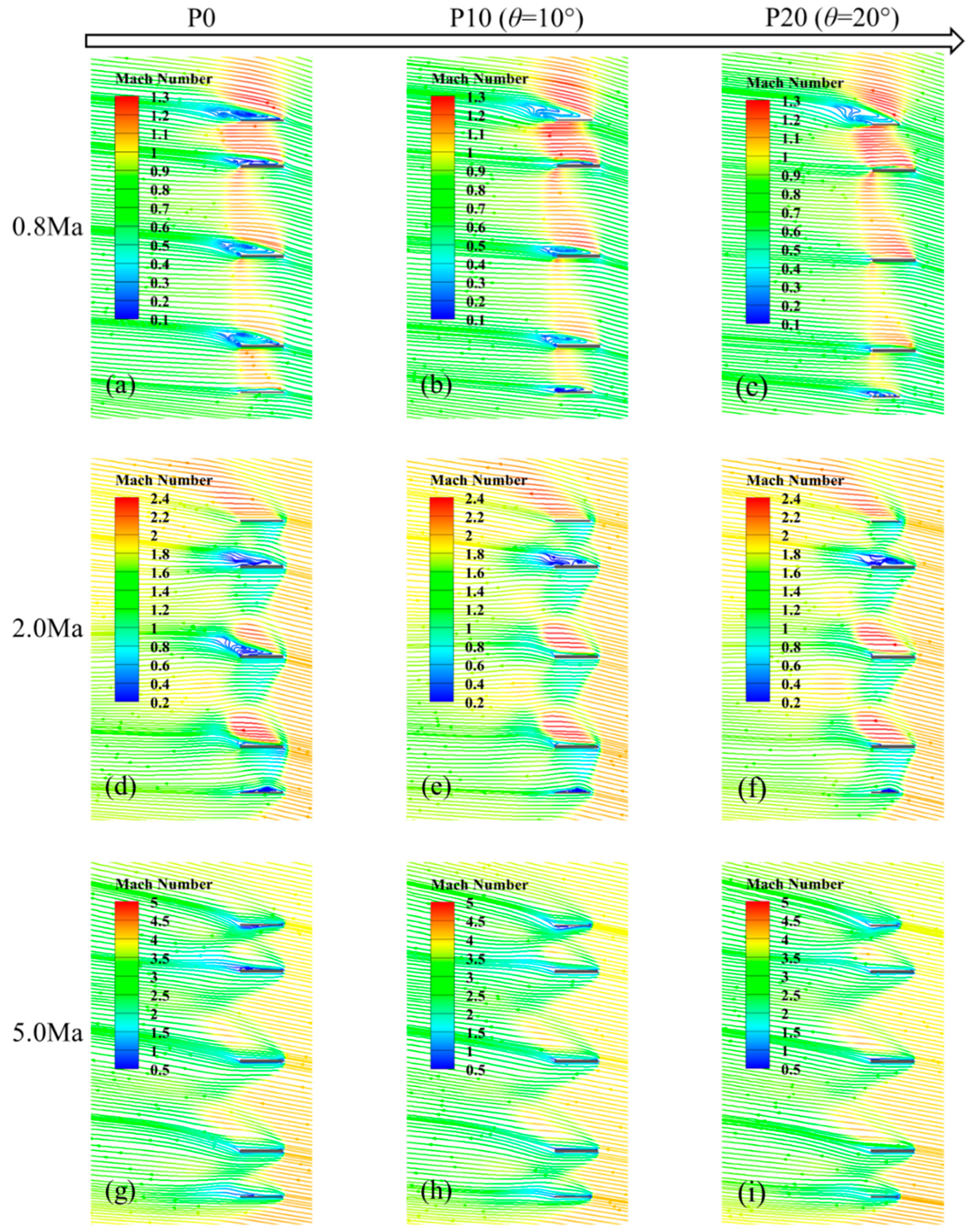
To explore the internal flow characteristics of grid fins, streamlines were extracted from feature profiles of both the baseline and the locally swept-back configurations for flow field visualization analysis, as shown in Figure 10.
For the baseline configuration (P0), at the freestream Mach number 0.8, (Figure 10a), the airflow accelerates to supersonic speeds within the grid cells, forming local shock waves before decelerating to subsonic flow at the exit. Simultaneously, separation vortices form in the leeward region of the grid cells, which leads to the flow choking phenomenon and increases the drag coefficient. Furthermore, the generation of local shock waves leads to notable variations in the pressure distribution over the grid fin surface, enhancing the pressure disparity between the upper and lower surfaces, which in turn results in a rise in lift. As the Mach number rises to 0.9, the flow choke intensifies further, and at this point, both the drag and lift coefficients reach their peak values. When the Mach number is 2.0, the oblique shock wave is formed by the impact of supersonic airflow on the grid fin’s leading edge (Figure 10d). Although the post-shock airflow experiences energy dissipation, it still maintains supersonic flow within the cells. Under these conditions, the separation vortices diminish, improving flow choke and reducing drag coefficient. Notably, the intersecting oblique shock waves interfere with each other between adjacent grid walls, leading to a reduction in the fin’s lift coefficient. As the Mach number rises further to 5.0, the oblique shock wave at the leading edge exhibits a smaller angle and attaches closer to the wall surfaces (Figure 10g). Flow separation virtually disappears, and the shock interaction zone shifts toward the exit, causing the airflow between grid walls to become nearly independent. Consequently, the aerodynamic characteristics approach those of a conventional planar fin, resulting in a reduction in the lift coefficient.
For the locally swept-back configuration (P10, P20), its flow field and shock wave characteristics at different Mach numbers are similar to those of the baseline, but the locally swept-back configuration effectively improves flow choke and reduces drag coefficient. At Mach 0.8 (Figure 10b), the swept-back angle significantly suppresses flow separation in the leeward region, markedly reducing the scale of separation vortices. With an increased swept-back angle (Figure 10c), flow separation even disappears in certain regions. At Mach 2.0 (Figure 10e,f) and 5.0 (Figure 10h,i), the airflow undergoes more gradual directional changes when passing through the swept-back grid walls, with the leading-edge oblique shock angle slightly decreasing and shock intensity consequently weakening, further reducing flow resistance. Significantly, although the locally swept-back configuration decreases the lifting surface area, it attains a substantial weight saving with negligible compromise to the aerodynamic efficiency.

3.5. Effects of θ on Aerodynamic Loads

In the recovery process of a reusable flying object, owing to the atmospheric compression effect and the severe friction between the surface of the grid fin and the airflow, the thinner fin surface is subjected not only to substantial aerodynamic heating but also to the aerodynamic force loading associated with a high dynamic pressure. Aerodynamic heat and aerodynamic pressure are obtained by a calculation, and the effect of the locally swept-back angle (θ) on aerodynamic loads is analyzed based on the baseline grid fin.
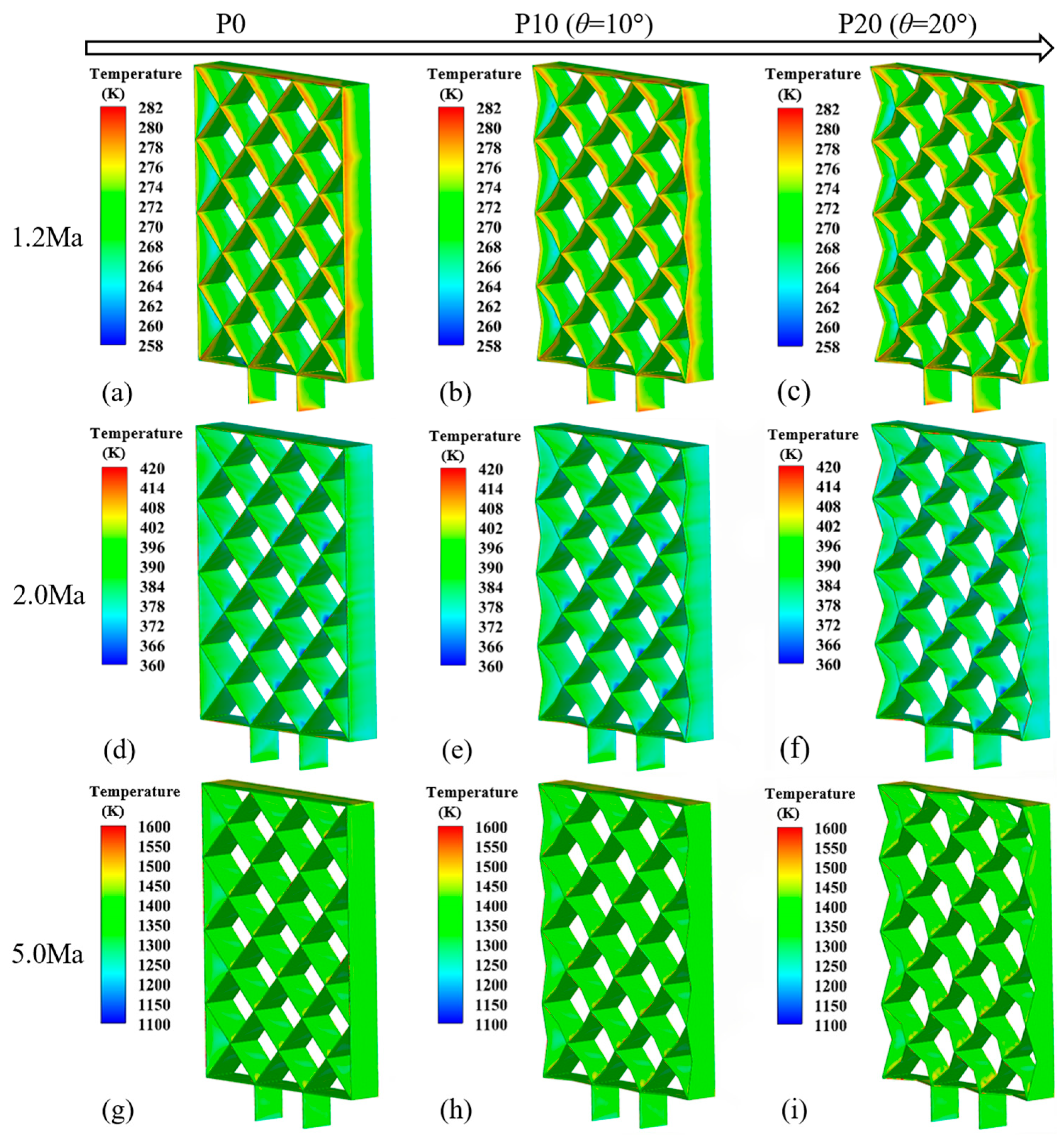
Figure 11 shows the contours of aerodynamic heat for the baseline and the locally swept-back configurations at different Mach numbers. Due to the large number of calculation conditions, only some of the resulting contours are presented. It can be observed that for all grid fins, the leading edge is subjected to the most intense aerodynamic heating, with the corresponding temperature reaching its peak, particularly in the regions where the grids intersect. Therefore, due to the effect of flow viscosity, the airflow velocity experiences a sharp decline and may even approach zero, forming a stagnation point. At this time, almost all of the airflow’s kinetic energy is dissipated and converted into heat energy, resulting in a sharp increase in temperature. As the Mach number increases, the surface temperature of the grid fin increases significantly, while the extent of the high-temperature region at the leading edge decreases. As described in Section 3.4, the locally swept-back configuration slightly reduces the shock angle, thereby weakening the shock intensity and lowering the total temperature of the airflow behind the shock. However, the swept-back configuration also reduces the effective area of the grid fin. The combination of shock weakening and area reduction leads to a negligible impact of the locally swept-back configuration on the overall temperature. Consequently, a comparison of the aerodynamic heat contours for different θ at a unified scale reveals a high degree of consistency in the temperature distribution across all configurations at each specific Mach number.
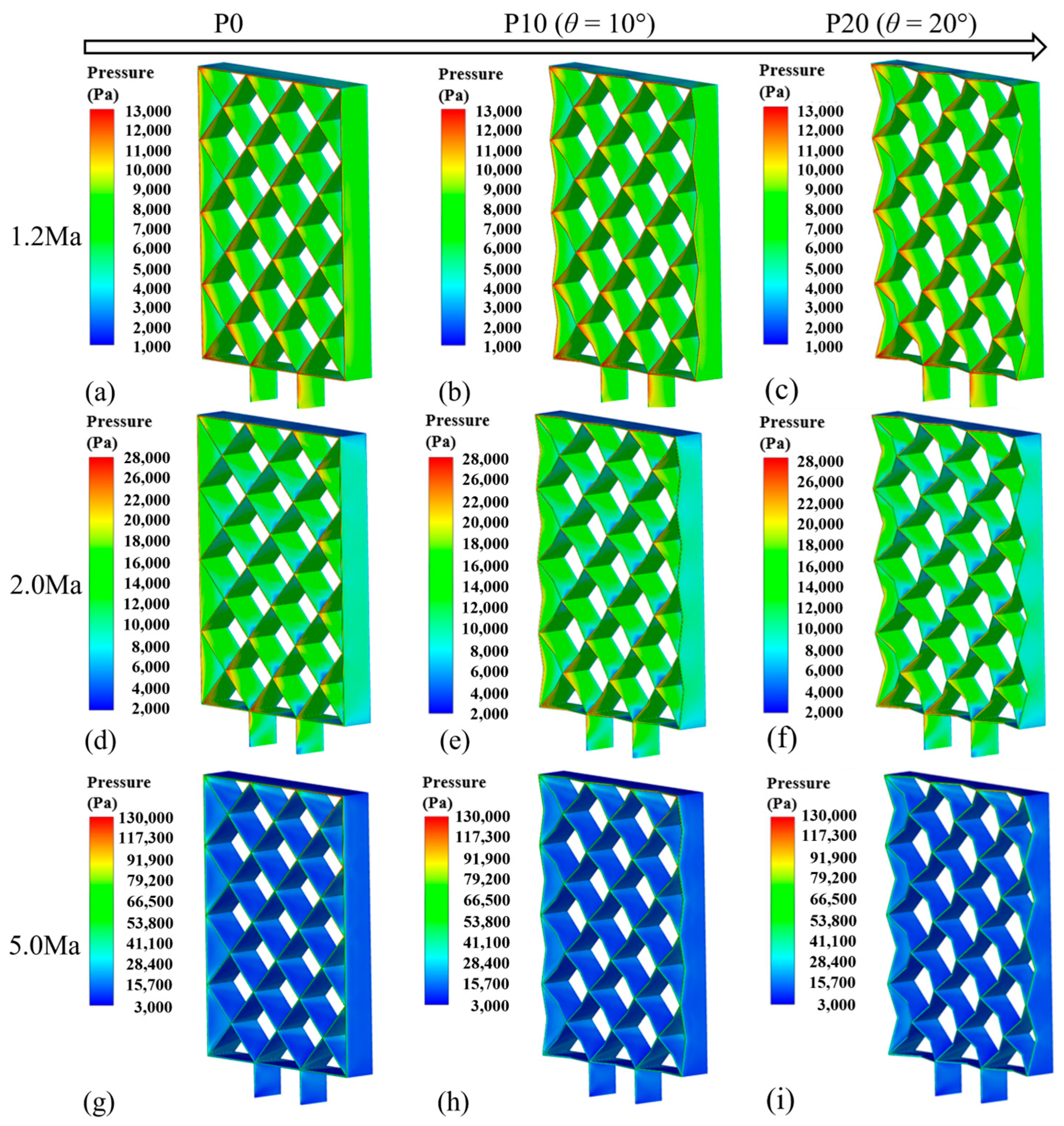
Figure 12 presents the aerodynamic pressure contours of the baseline and the locally swept-back configuration at different Mach numbers. The distribution characteristics closely resemble those observed in Figure 11. Owing to the abrupt deceleration of the airflow, the pressure reaches a local maximum in the stagnation region of the leading edge. As the Mach number increases, the airflow velocity at the leading edge of the grid fin becomes higher, and the compression effect of the shock wave becomes stronger, resulting in a significant increase in the pressure in the stagnation region. Similarly, the consistency of the pressure contours between different θ is observed at the same Mach number, which can be attributed to the basic balance between the two competing effects of the reduction in wave drag and the reduction in effective area induced by the locally swept-back configuration. This suggests that the effect of θ on aerodynamic heat and aerodynamic pressure is negligible.

3.6. Effects of θ on Structural Responses

The structural integrity of the grid fin, with a focus on its static strength, was analyzed by employing a coupled fluid–thermo–structure method. Here, aerodynamic heat and pressure served as the thermal and mechanical loads, respectively. Based on the results of the baseline configuration, the effect of the locally swept-back angle (θ) on the stress and displacement distribution was further investigated.
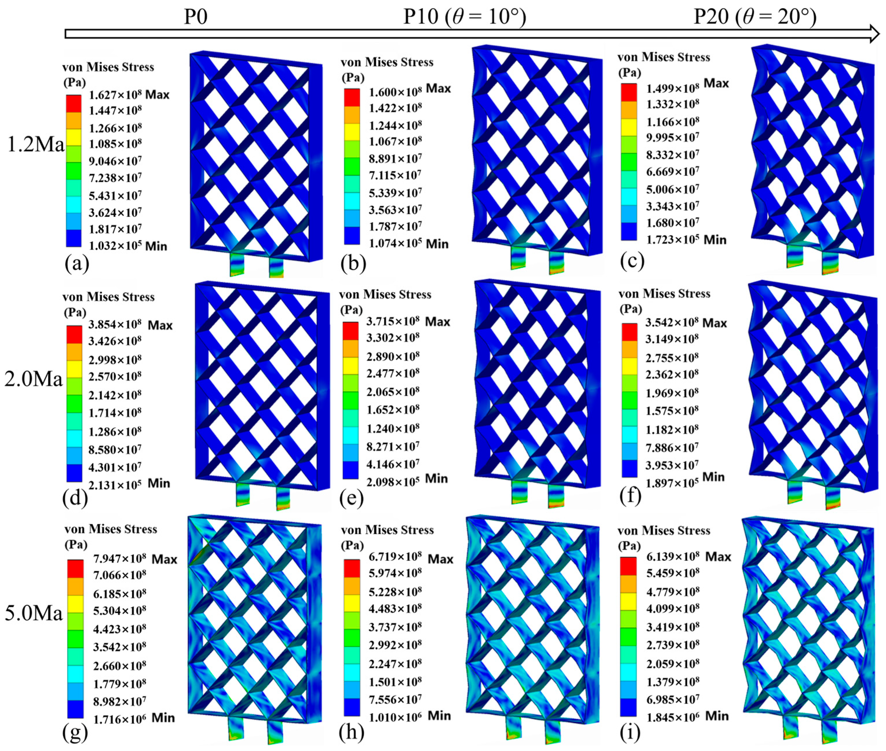
As shown in Figure 13, the von Mises stress increases with the Mach number for all grid fins. Furthermore, stress concentration occurs at the bottom of the grid fin, precisely at the junction where it connects to the body. Consequently, during the design process, it is necessary to attach great importance to the strength of the bottom of the grid fin. It is noteworthy that, at the same Mach number, the stress distributions correspond to different θ that exhibit similar characteristics. Additionally, the maximum stress of the locally swept-back configuration is slightly lower than that of the baseline.
Different from the stress results, the large deformation region of the grid fin changes with the Mach number (Figure 14). Generally, the large deformation region is mainly at the outer end of the grid fin, which is far from the connection part with the body. Similarly to the free end of a cantilever structure, the outer end is more likely to experience larger deformation than other parts under the impact of the airflow. As the Mach number increases, the large deformation region changes from the right side of the outer end to the front side, and then moves to the trailing edge of the front side. By comparing the deformation contours of different θ, it is found that both the distribution of deformation and the numerical values exhibit relatively similar characteristics, with no significant differences. A comprehensive analysis of stress and deformation reveals that the variation in θ has no substantial impact on the strength and stiffness of the grid fin. This is due to the fact that the overall magnitude and distribution of the aerodynamic loads exhibit no significant change for the investigated θ values. Here, the influence of θ on the structural integrity is negligible.

4. Conclusions

In this study, a lightweight method of a grid fin based on a locally swept-back configuration was proposed. The aerodynamic characteristics and structural mechanical responses of the baseline grid fin and the locally swept-back grid fin under Mach number 0.8~5 were numerically simulated using computational fluid dynamics and a fluid–thermo–structure coupling method. Through the systematic investigation of the effects of a locally swept-back angle on aerodynamic coefficients, aerodynamic loads, and structural static strength, an effective balance among weight saving, aerodynamic performance, and structural integrity was achieved. The main conclusions are as follows:
(1) The lightweight locally swept-back configuration significantly enhances aerodynamic performance by effectively improving airflow choke and reducing flow resistance, while having no substantial impact on aerodynamic loads or structural integrity. It should be noted, however, that the reduction in effective area leads to a certain decrease in lift, particularly at high Mach numbers. Therefore, the trade-off between lift and drag across different flight phases should be carefully considered in the design process.
(2) The adjustment of the locally swept-back angle enables aerodynamic performance improvement and weight saving across different Mach numbers while maintaining structural integrity. Specifically, at Mach 0.8, 1.5, and 2.0, the 20° swept-back configuration achieved a 13.2% weight saving while improving aerodynamic performance. At Mach 0.9, the 15° configuration delivered optimal aerodynamic enhancement with a 10% weight saving. These results demonstrate that the locally swept-back configuration has good adjustability and can be specifically optimized according to the aerodynamic performance and weight saving requirements of specific tasks.
(3) With all operating Mach numbers evaluated, a locally swept-back angle of 15° showed an excellent balance between weight saving, aerodynamic performance, and structural integrity. This indicates that the locally swept configuration holds significant potential for lightweight design in wide-speed-range aerospace vehicles.
(4) In structural design, special attention should be paid to the stress concentration area at the connection between the grid fin and the body, as well as the stiffness–weakness region at the outer end of the grid fin, where the stress distribution and stiffness characteristics were directly related to the overall structural stability and reliability.
The lightweight locally swept-back configuration proposed in this study represents a good attempt to balance the weight saving, aerodynamic performance, and structural integrity, offering important insights for the lightweight design of grid fins. Future research will focus on the multi-objective optimization of grid fins under wide-speed-range conditions to achieve the optimal geometric configuration.

Author Contributions

Conceptualization, methodology, and resources: M.Z., F.X., and Y.L.; Formal analysis, investigation, and writing—original draft preparation: Y.L.; Writing—review and editing and supervision: M.Z.; Funding acquisition: M.Z. and F.X. All authors have read and agreed to the published version of the manuscript.

Funding

This research was funded by the National Natural Science Foundation of China (52321002) and the Shuguang Program of Shanghai Education Commission (21SG30).

Data Availability Statement

The data can be obtained by contacting the corresponding author.

Conflicts of Interest

The authors declare no conflicts of interest.

References

  1. Adilov, N.; Alexander, P.; Cunningham, B.; Albertson, N. An analysis of launch cost reductions for low earth orbit satellites. Econ. Bull. 2022, 42, 1561–1574. [Google Scholar]
  2. Salehi Paniagua, K.; García-Fogeda, P.; Arévalo, F. Aeroelastic stability of an aerial refueling hose–drogue system with aer-odynamic grid fins. Aerospace 2023, 10, 481. [Google Scholar] [CrossRef]
  3. Bunescu, I.; Hothazie, M.V.; Stoican, M.G.; Pricop, M.V.; Onel, A.I.; Afilipoae, T.P. Numerical Study of the Basic Finner Model in Rolling Motion. Aerospace 2025, 12, 371. [Google Scholar] [CrossRef]
  4. DeSpirit, J.; Milton, V.; Washington, W.D. CFD investigation of canard-controlled missile with planar and grid fins in supersonic flow. In Proceedings of the AIAA Atmospheric Flight Mechanics Conference and Exhibit, Monterey, CA, USA, 5–8 August 2002. AIAA 2002-4509. [Google Scholar] [CrossRef]
  5. Fan, H.Y.; Mi, B.G.; Liu, H.Y.; Yu, J.Y. A grid fusion lifting surface and its flow control mechanism at high angles of attack. Int. J. Aerosp. Eng. 2022, 2022, 7788011. [Google Scholar] [CrossRef]
  6. Spisz, T.S.; Taylor, J.C.; Gibson, D.; Kennerly, S.; Osei-Wusu, K.; Scriven, G.; Pottebaum, T.; Horvath, T.J.; Schwartz, R.; Tack, S.; et al. Processing infrared imagery of the SpaceX Falcon first stage reentry during CRS-4 mission. In Proceedings of the AIAA Space and Astronautics Forum and Exposition, American Institute of Aeronautics and Astronautics, Orlando, FL, USA, 12–14 September 2017. [Google Scholar] [CrossRef]
  7. Lee, K.-O. An analysis of launch vehicle development strategy of SpaceX. J. Korean Soc. Propuls. Eng. 2019, 23, 72–86. [Google Scholar] [CrossRef]
  8. Choo, K.; Mun, H.; Nam, S.; Cha, J.; Ko, S. A survey on recovery technology for reusable space launch vehicle. J. Korean Soc. Propuls. Eng. 2018, 22, 138–151. [Google Scholar] [CrossRef]
  9. Miller, M.S.; Washington, W.D. An experimental investigation of grid fin drag reduction techniques. In Proceedings of the 12th Applied Aerodynamics Conference, Colorado Springs, CO, USA, 20–23 June 1994. [Google Scholar] [CrossRef]
  10. Tripathi, M.; Sucheendran, M.M.; Misra, A. Experimental analysis of cell pattern on grid fin aerodynamics in subsonic flow. Proc. Inst. Mech. Eng. Part G J. Aerosp. Eng. 2020, 234, 537–562. [Google Scholar] [CrossRef]
  11. Tripathi, M.; Sucheendran, M.M.; Misra, A. Effect of aspect ratio variation on subsonic aerodynamics of cascade type grid fin at different gap-to-chord ratios. Aeronaut. J. 2020, 124, 472–498. [Google Scholar] [CrossRef]
  12. Tripathi, M.; Sucheendran, M.M.; Misra, A. Effect of chord variation on subsonic aerodynamics of grid fins. In Design and Development of Aerospace Vehicles and Propulsion Systems, Lecture Notes in Mechanical Engineering; Springer: Singapore, 2021; pp. 105–128. [Google Scholar] [CrossRef]
  13. Tripathi, M.; Misra, A.; Sucheendran, M.M. Effect of planar member cross-section on cascade fin aerodynamics. J. Spacecr. Rockets 2019, 56, 744–760. [Google Scholar] [CrossRef]
  14. Dinh, V.-S.; Dinh, C.-T.; Pham, V.-S. Numerical study on aerodynamic characteristics of the grid fins with different grid patterns. Phys. Fluids 2023, 35, 123117. [Google Scholar] [CrossRef]
  15. Zeng, Y.; Cai, J.S.; Debiasi, M.; Chng, T.L. Numerical study on drag reduction for grid-fin configurations. In Proceedings of the 47th AIAA Aerospace Sciences Meeting Including the New Horizons Forum and Aerospace Exposition, Orlando, FL, USA, 5–8 January 2009. [Google Scholar] [CrossRef]
  16. Zeng, Y. Drag reduction for sweptback grid fin with blunt and sharp leading edges. J. Aircr. 2012, 49, 1526–1531. [Google Scholar] [CrossRef]
  17. Cai, J.S. Numerical study on choked flow over grid-fin configurations. J. Spacecr. Rockets 2009, 46, 949–956. [Google Scholar] [CrossRef]
  18. Debiasi, M.; Yan, Z.; Loon, C.T. Swept-back grid fins for transonic drag reduction. In Proceedings of the 28th AIAA Applied Aerodynamics Conference, Chicago, IL, USA, 28 June–1 July 2010. [Google Scholar] [CrossRef]
  19. Debiasi, M. Measurements of the forces and moments generated by swept-back grid fins. In Proceedings of the 30th AIAA Applied Aerodynamics Conference, New Orleans, LA, USA, 25–28 June 2012. [Google Scholar] [CrossRef]
  20. Schülein, E.; Guyot, D. Novel high-performance grid fins for missile control at high speeds: Preliminary numerical and experimental investigations. In Proceedings of the RTO Applied Vehicle Technology Panel (AVT) Business Meeting Week, Amsterdam, The Netherlands, 15–18 May 2006. [Google Scholar]
  21. Guyot, D.; Schülein, E. Novel locally swept lattice wings for missile control at high speeds. In Proceedings of the 45th AIAA Aerospace Sciences Meeting and Exhibit, Reno, NV, USA, 8–11 January 2007. [Google Scholar] [CrossRef]
  22. Yadav, V.; Joshi, G.N.; Misra, A.; Tripathi, M. Effect on aerodynamic efficiency of cascade fin due to presence of locally swept planar members at subsonic speed. In Recent Advancements in Mechanical Engineering; Springer: Singapore, 2024; pp. 361–372. [Google Scholar] [CrossRef]
  23. Yadav, V.; Misra, A.; Joshi, G.N.; Tripathi, M. Effect of complex internal grid pattern variations on the subsonic aerodynamic characteristics of grid-fins. Aeronaut. J. 2025, 129, 2712–2740. [Google Scholar] [CrossRef]
  24. Lee, Y. Experimental study on aerodynamic characteristics of generic missile configuration with grid fin in transonic flow. Int. J. Aeronaut. Space Sci. 2025, 26, 2214–2225. [Google Scholar] [CrossRef]
  25. Ye, K.; Ye, Z.Y.; Li, C.N.; Wu, J. Effects of the aerothermoelastic deformation on the performance of the three-dimensional hypersonic inlet. Aerosp. Sci. Technol. 2019, 84, 747–762. [Google Scholar] [CrossRef]
  26. Huang, C.D.; Liu, W.; Yang, G.W. Numerical studies of static aeroelastic effects on grid fin aerodynamic performances. Chin. J. Aeronaut. 2017, 30, 1300–1314. [Google Scholar] [CrossRef]
  27. Liu, F.; Han, Z.H.; Zhang, Y.; Song, K.; Song, W.P.; Gui, F.; Tang, J.B. Surrogate-based aerodynamic shape optimization of hypersonic flows considering transonic performance. Aerosp. Sci. Technol. 2019, 93, 105345. [Google Scholar] [CrossRef]
  28. Washington, W.D.; Miller, M.S. Grid fins—A new concept for missile stability and control. In Proceedings of the 31st Aerospace Sciences Meeting & Exhibit, Reno, NV, USA, 11–14 January 1993. [Google Scholar] [CrossRef]
  29. Sharma, N.; Kumar, R. Missile grid fins analysis using computational fluid dynamics: A systematic review. INCAS Bull. 2019, 11, 151–169. [Google Scholar] [CrossRef]
Figure 1. The existing locally swept-back design method: (a) geometry of baseline grid fin and (b) locally swept-back grid fin [20,21,22].
Aerospace 12 00899 g001
Figure 2. Schematic of the configurations: (a) definition of the first sub-stage; (b) front view of grid fin; (c) side view of baseline grid fin; (d) side view of locally swept-back grid fin.
Aerospace 12 00899 g002
Figure 3. Configuration of computing model: (a) P0; (b) Pθ; (c) half of the first sub-stage.
Aerospace 12 00899 g003
Figure 4. Mesh distribution of baseline configuration: (a) on the rocket first sub-stage surface; (b) within the grid cells; (c) on the symmetry plane.
Aerospace 12 00899 g004
Figure 5. Grid independence test on the baseline configuration.
Aerospace 12 00899 g005
Figure 6. Grid fin wind tunnel model [28].
Aerospace 12 00899 g006
Figure 7. Geometry model for validation.
Aerospace 12 00899 g007
Figure 8. Validation results of CN at the Mach (a) 0.8; (b) 1.1; (c) 2.5.
Aerospace 12 00899 g008
Figure 9. Aerodynamic coefficient comparison of baseline and locally swept-back grid fins: (a) CL; (b) CD; (c) CL/CD.
Aerospace 12 00899 g009
Figure 10. Streamline of baseline and locally swept-back configurations: (a) P0 at 0.8Ma; (b) P10 at 0.8Ma; (c) P20 at 0.8Ma; (d) P0 at 2.0Ma; (e) P10 at 2.0Ma; (f) P20 at 2.0Ma; (g) P0 at 5.0Ma; (h) P10 at 5.0Ma; (i) P20 at 5.0Ma.
Aerospace 12 00899 g010
Figure 11. Aerodynamic heat contours of baseline and locally swept-back configurations: (a) P0 at 1.2Ma; (b) P10 at 1.2Ma; (c) P20 at 1.2Ma; (d) P0 at 2.0Ma; (e) P10 at 2.0Ma; (f) P20 at 2.0Ma; (g) P0 at 5.0Ma; (h) P10 at 5.0Ma; (i) P20 at 5.0Ma.
Aerospace 12 00899 g011
Figure 12. Aerodynamic pressure contours of baseline and locally swept-back configurations: (a) P0 at 1.2Ma; (b) P10 at 1.2Ma; (c) P20 at 1.2Ma; (d) P0 at 2.0Ma; (e) P10 at 2.0Ma; (f) P20 at 2.0Ma; (g) P0 at 5.0Ma; (h) P10 at 5.0Ma; (i) P20 at 5.0Ma.
Aerospace 12 00899 g012
Figure 13. von Mises stress contours of baseline and locally swept-back configurations: (a) P0 at 1.2Ma; (b) P10 at 1.2Ma; (c) P20 at 1.2Ma; (d) P0 at 2.0Ma; (e) P10 at 2.0Ma; (f) P20 at 2.0Ma; (g) P0 at 5.0Ma; (h) P10 at 5.0Ma; (i) P20 at 5.0Ma.
Aerospace 12 00899 g013
Figure 14. Deformation contours of baseline and locally swept-back configurations: (a) P0 at 1.2Ma; (b) P10 at 1.2Ma; (c) P20 at 1.2Ma; (d) P0 at 2.0Ma; (e) P10 at 2.0Ma; (f) P20 at 2.0Ma; (g) P0 at 5.0Ma; (h) P10 at 5.0Ma; (i) P20 at 5.0Ma.
Aerospace 12 00899 g014
Table 1. Material properties of GH4169.
Temperature
K
Density
kg/m3
Elasticity
Modulus
GPa
Poisson
Ratio
Thermal
Conductivity
W/(m·K)
Specific
Heat
J/(kg·K)
Linear Expansion
Coefficient
×10−6 (K−1)
2293.15~1273.158240204~1040.3~0.3313.4~30.4427~707.411.8~18.7
Table 2. RPθ across the whole Mach range investigated and RPθavg.
θ (°)5101520
RPθ (%)0.8 Ma0.02−0.010.271.49
0.9 Ma0.320.310.34−0.03
1.2 Ma−0.04−0.04−0.26−0.54
1.5 Ma0.330.330.570.71
2.0 Ma−0.130.240.570.94
3.0 Ma−1.01−1.17−0.65−3.20
4.0 Ma0.00−0.75−1.89−3.75
5.0 Ma−1.59−2.04−1.04−3.91
RPθavg (%)−0.26−0.39−0.26−1.04
Table 3. WSθ and LWθavg for different θ.
θ (°)5101520
WSθ (%)3.356.679.9513.20
LWθavg (%)7.835.842.637.89
Disclaimer/Publisher’s Note: The statements, opinions and data contained in all publications are solely those of the individual author(s) and contributor(s) and not of MDPI and/or the editor(s). MDPI and/or the editor(s) disclaim responsibility for any injury to people or property resulting from any ideas, methods, instructions or products referred to in the content.