1. Introduction
The “New Space” paradigm has accelerated the deployment of small satellites, driven by advances in manufacturing, launch opportunities, and commercial investment. This proliferation has increased the demand for communication links that can provide fiber-like throughput, low latency, and secure operation in dynamic orbital environments [
1]. Free-space optical (FSO) communication has emerged as a promising alternative to radio-frequency (RF) links. Its advantages include virtually unlimited unlicensed bandwidth, higher data rates, reduced power consumption, compact terminals, and immunity to electromagnetic interference, making it well-suited for small satellite missions [
1]. Technology surveys highlight the maturing ecosystem of beyond-5G FSO components, while system-level studies describe the growing role of inter-satellite laser links and direct-to-Earth optical downlinks in proliferated Low Earth Orbit (LEO) constellations [
2,
3].
Despite these advantages, FSO deployment is constrained by atmospheric and platform-induced impairments. Optical beams are strongly affected by turbulence, leading to scintillation, beam wander, and beam spreading [
4,
5]. The resulting temporal correlation of fading, typically on the order of milliseconds, generates burst errors that conventional error-control schemes are not optimized to handle. Pointing errors add further penalties due to spacecraft jitter, vibrations, and thermal distortions, which compound turbulence fading and degrade link reliability [
6,
7].
Recent on-orbit demonstrations illustrate both the potential and limitations of optical links. NASA’s TBIRD mission demonstrated record-breaking >200 Gbps downlinks from a 6U CubeSat under clear-sky conditions [
8]. To improve reliability, TBIRD employed a selective Automatic Repeat Request (ARQ) protocol, underscoring that atmospheric fading cannot be ignored even in favorable conditions. In contrast, long-term in-orbit experiments such as OICETS and SOTA have clearly shown that turbulence-induced scintillation and pointing stability constitute the dominant impairments for operational optical links [
9,
10]. These contrasting experiences highlight the necessity of evaluating optical systems under realistic fading dynamics. It has also been shown that interleaving provides an effective means of mitigating burst errors arising from dynamic pointing and tracking losses in turbulent channels [
11].
In recognition of these challenges, the Consultative Committee for Space Data Systems (CCSDS) established a working group to standardize optical communication protocols. The Optical On-Off Keying (O3K) specification, documented in CCSDS 142.0-P-1, defines On-Off Keying (OOK) modulation, Low-Density Parity-Check (LDPC) coding (rates 1/2 and 9/10), and deep interleaving to mitigate burst errors [
12]. The most recent revision remains under draft review and is undergoing final modifications prior to its adoption as a Recommended Standard. Importantly, the standard explicitly accounts for direct-to-Earth (DTE) links by mandating support for extremely deep interleaving depths (up to
codewords), ensuring robustness even under strongly correlated turbulence and pointing dynamics. O3K therefore targets direct-to-Earth and inter-satellite applications where simplicity and robustness are prioritized. Recent hardware demonstrations have validated O3K-compliant coding and synchronization, confirming feasibility across a wide range of data rates [
13,
14].
While the CCSDS O3K standard incorporates robust design features, including the use of deep interleaving to address atmospheric impairments, research that explicitly considers the temporal correlation of turbulence and pointing errors remains scarce. Link-budget analyses typically focus on average losses over long time horizons, without capturing the short-term fluctuations that drive burst errors in practice [
15,
16]. Similarly, many analytical and simulation-based studies assume memory-less fading models, thereby overlooking the temporal dynamics that strongly influence error statistics [
17,
18]. More recently, it has been demonstrated that interleaving can mitigate burst errors under temporally correlated fading conditions [
11]. However, this finding was not obtained within the practical standard framework, underscoring the need for standard-compliant evaluations such as those conducted in this study.
This paper does not propose new coding or modulation techniques. Instead, it presents what we believe to be the first end-to-end CCSDS O3K-compliant simulation framework under realistically modeled turbulence and pointing conditions. The simulator implements the full CCSDS 142.0-B-1 chain, including synchronization markers, LDPC coding/decoding, and interleaving, coupled with ITU-R-based turbulence generation and an autoregressive pointing-error process [
5]. Monte Carlo results quantify the impact of turbulence strength, coherence time, and interleaving depth on Bit Error Rate (BER) performance. The findings highlight the role of deep interleaving in mitigating temporally correlated fading and demonstrate the significant penalties imposed when turbulence and pointing errors act jointly. These results provide practical benchmarks for configuring O3K-compliant optical links in LEO downlinks, inter-satellite networks, and small-satellite missions.
2. CCSDS O3K Protocol Implementation
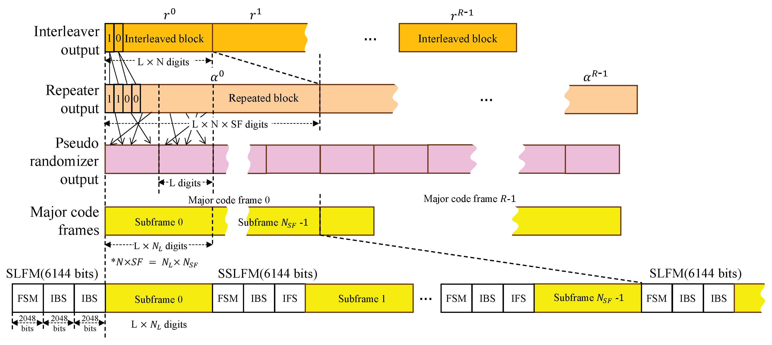
The implemented CCSDS link-level simulator follows the complete transmit chain as defined in the CCSDS 142.0-P-1 standard. The system processes randomly generated transfer frames through sequential signal-processing stages to achieve robust optical communication under atmospheric turbulence conditions. The overall transmitter architecture up to the channel interleaving stage is depicted in
Figure 1, while the subsequent operations—covering repetition, randomization, and final sync-layer frame generation—are detailed in
Figure 2.
At the coding and synchronization layer, fixed-length transfer frames are received from the Data Link Protocol layer and processed into binary vectors suitable for the physical layer interface. Transfer frame adaptation begins with the generation of
frames,
, derived from CCSDS protocols such as the TM Space Data Link Protocol [
19], the Advanced Orbiting System, or the Unified Space Data Link Protocol. Each frame has a fixed bit length defined by the selected protocol.
A 32-bit Attached Sync Marker (ASM) of 0x1ACFFC1D is appended to each transfer frame to form Synchronization-Marked Transfer Frames (SMTFs). The SMTFs are then segmented into information blocks of length k according to the selected code rate r. For code rates 1/2 and 9/10, k equals 15,360 and 27,648 bits, respectively. If the final block is shorter than k, zero padding is applied. The total number of blocks becomes , where P denotes padding bits.
Error protection in the CCSDS O3K framework can be realized using either Reed– Solomon (RS) or LDPC codes. In this study, we restrict attention to LDPC coding, as it represents the more relevant option for Earth–space optical links subject to atmospheric turbulence and pointing impairments. For rate–1/2 operation, a Protograph-Based Raptor-Like (PBRL) LDPC code generates codewords of length bits, whereas rate–9/10 employs an Accumulate–Repeat–Accumulate (ARA) code with . Systematic puncturing reduces both code rates to a standardized length of 30,720 bits, corresponding to 2560 punctured bits for rate–1/2 and 1536 punctured bits for rate–9/10.
Channel interleaving plays a critical role in mitigating burst errors caused by turbulence. Since the coherence time of atmospheric fading extends over milliseconds—much longer than the duration of a single codeword—block interleaving is applied to distribute bits temporally. Each punctured codeword
, with
, is written row-wise into an interleaver matrix and read column-wise in blocks of length
K, as illustrated in
Figure 3. Parameters
K and
N (interleaving depth) are tuned for memory efficiency and error protection. The total memory requirement is
bytes; for
, the memory approaches 7.5 GB, and increases to approximately 15 GB when ping-pong buffering is employed. In practice,
N is chosen to balance memory constraints with the desired burst-error resilience.
Following interleaving, the data stream may undergo optional repetition coding with factors , effectively reducing the code rate to . While repetition enhances error protection, it introduces long runs of identical bits, which can obscure symbol transitions and thereby complicate timing and bit synchronization at the receiver. To mitigate this issue, a pseudo-randomization stage applies modulo-2 addition of the code stream with a pseudo-random sequence , generated by a 15-bit Linear Feedback Shift Register. The sequence resets after each block of L bits, ensuring sufficient symbol transitions for reliable synchronization.
The final step organizes data into sync-layer frames containing Frame Sync Markers (FSMs), In-Band Signaling (IBS) fields, and Interleaver Frame Signaling (IFS). Each of these fields is generated using a 2048-bit Gold code, selected for its low cross-correlation properties to ensure robust detection. The IBS conveys essential transmitter parameters—coding rate
r, repetition factor
, block size
K, and interleaver depth
N—to the receiver. A specific combination of these parameters defines a transmission mode, and each mode is associated with a distinct Gold code sequence. This design enables the receiver to reliably identify the active mode and automatically configure its processing chain. Start-of-frame detection is further supported by recognizing two consecutive IBS fields, which, together with FSM and IFS sequences, ensures reliable synchronization, demodulation, and decoding in O3K optical links. The overall structure of these post-interleaving stages is illustrated in
Figure 2.
4. Simulation Results and Discussion
4.1. Simulation Setup
The simulation scenario models a LEO satellite-to-ground optical downlink using parameters summarized in
Table 1, consistent with CCSDS O3K specifications. The system operates at 1550 nm (193 THz) with an elevation angle of
, which is a common configuration for optical downlinks. The ground-level turbulence strength is set to
, with an RMS wind speed of 30 m/s, representing a challenging scenario characterized by strong atmospheric turbulence [
3]. The receiver aperture diameter is set to 0.3 m, reflecting typical values for ground-based optical terminals.
The beam divergence angle
is set to 113 μrad, which is based on the OSIRIS4CUBE terminal specification [
15], and is representative of nominal values in CubeSat-class optical terminals. The standard deviation of the residual pointing jitter is assumed to be 1 arcsec. According to recent survey results, the pointing stability of state-of-the-art fine beam steering mechanisms lies in the range of ±10 arcsec to ±0.1 arcsec [
24], making 1 arcsec a conservative yet realistic value for residual jitter.
The fading channel analysis assumes a turbulence coherence time of 1 ms, representing time-varying atmospheric conditions [
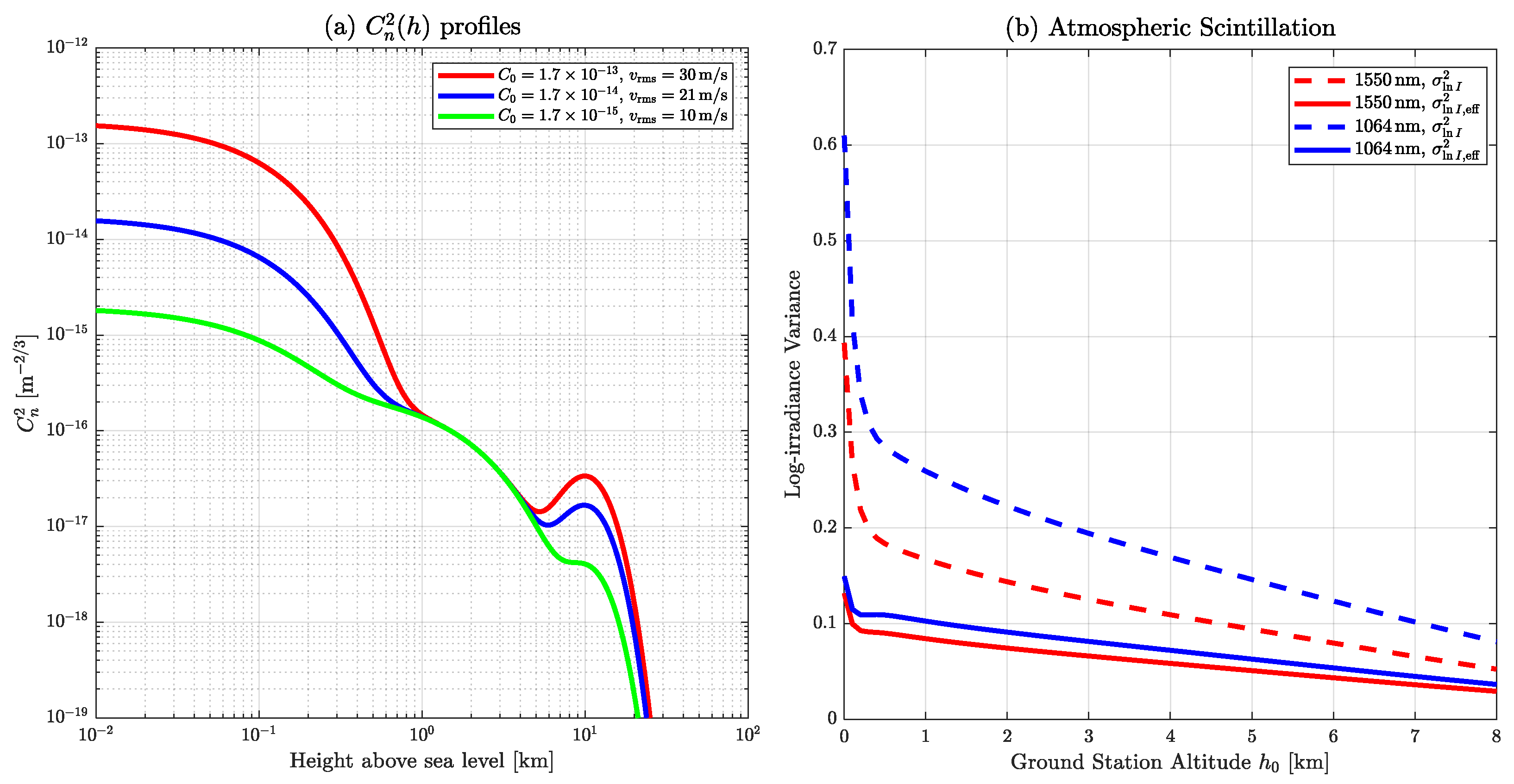
8]. A log-irradiance variance of 0.1 is used to model weak-to-moderate turbulence from
Figure 4. Interleaving depths of
and
are evaluated in order to study the tradeoff between memory requirements and error resilience. Simulations were performed for data rates of both 1 Gbps and 100 Mbps, enabling assessment of how symbol rate interacts with fading dynamics and interleaving effectiveness. Both LDPC code rates defined in CCSDS O3K (1/2 and 9/10) were initially considered. However, the
configuration was simulated only under Additive White Gaussian Noise (AWGN) conditions, while the
case was applied to fading channels.
This restriction reflects practical considerations in Monte Carlo analysis. For ms, obtaining statistically stable BER estimates requires a channel observation more than 5000 ms, which corresponds to approximately transmitted bits or 160,000 LDPC codewords. Simulating and decoding this volume of data with the full CCSDS chain is computationally prohibitive, especially under fading conditions where additional repetitions are required for convergence. Furthermore, in realistic LEO optical downlinks, the mode is more relevant, since high-rate codes such as are unlikely to provide sufficient margin under strong turbulence and pointing impairments. Accordingly, the fading-channel analysis concentrates on the more robust configuration, while results under AWGN serve as a baseline reference for comparison. This approach ensures both computational feasibility and practical relevance in assessing CCSDS O3K system performance.
At the receiver, inverse operations with soft-decision decoding are applied to recover the original transfer frames. The received signal is first processed to compute log-likelihood ratios (LLRs) for LDPC decoding. The LLR for bit
b is then defined as
where
denotes the total channel gain, obtained as the product of the turbulence-induced fading component
and the pointing-loss component
. Here,
y is the received sample, and
denotes the AWGN noise variance. Specifically,
follows a log-normal distribution to model scintillation, while
captures pointing-induced fading.
LDPC decoding is performed using the Sum–Product Algorithm (SPA) with a maximum of 50 iterations. The algorithm alternates between check-node updates, computed using hyperbolic tangent operations, and variable-node updates, which combine incoming messages through LLR summation. The decoding process terminates once a valid codeword is detected or the maximum iteration count is reached. While SPA provides near-optimal performance for the factor-graph representation, it incurs higher computational complexity compared to approximations such as the Min–Sum algorithm.
System performance is quantified in terms of the bit error rate (BER), computed as the ratio of incorrectly decoded bits to the total transmitted information bits. In addition, we also evaluate the frame error rate (FER), defined as the ratio of incorrectly decoded codewords to the total transmitted codewords, which provides a direct measure of end-to-end reliability in CCSDS O3K systems. Performance curves are presented as a function of the signal-to-noise ratio (SNR), where the effective SNR is defined as
where
is the transmit power and
denotes expectation over the fading distribution. This formulation ensures that fading-induced power fluctuations are properly incorporated into the performance metric.
4.2. Simulation Results and Performance Evaluation
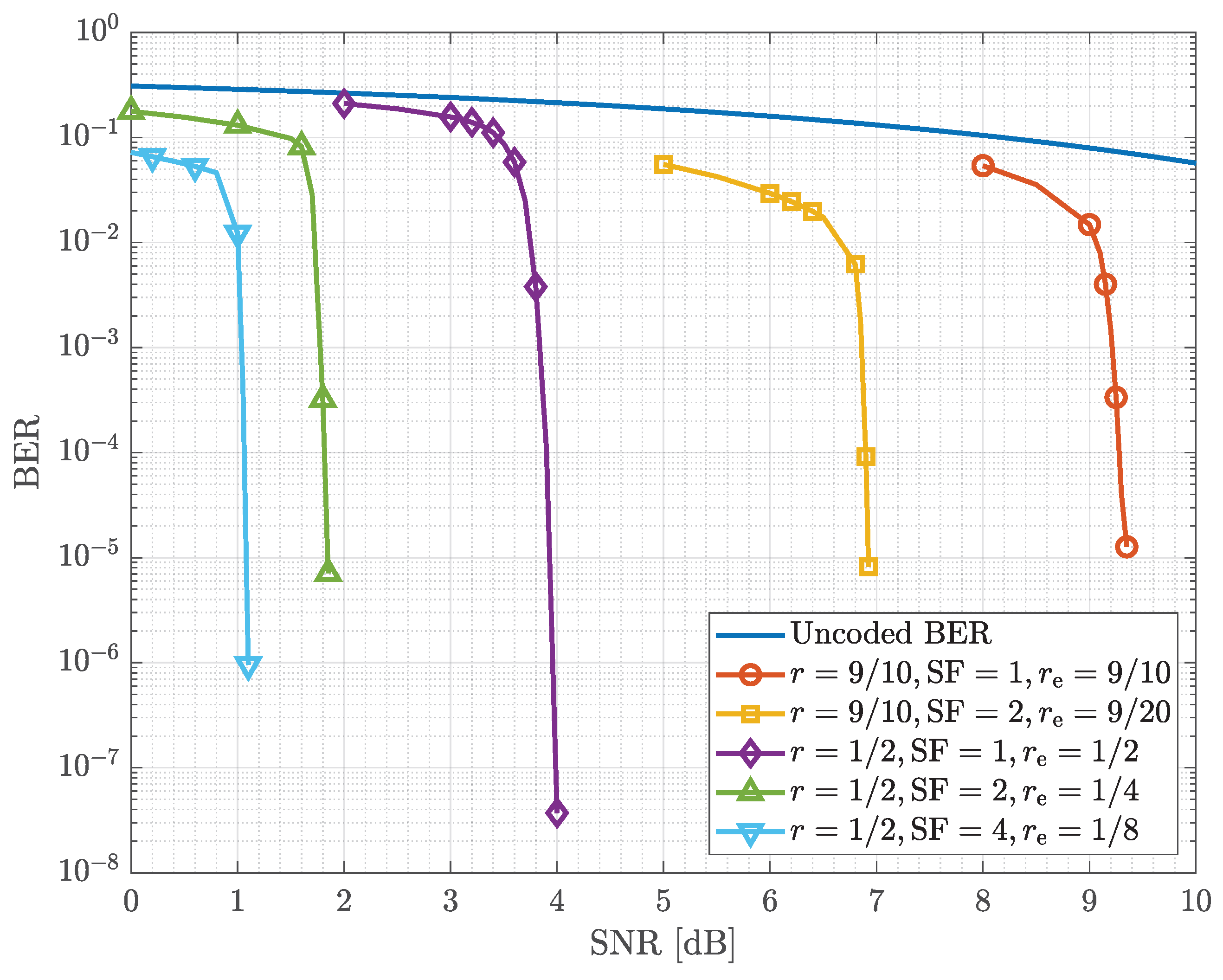
As a baseline, the performance of CCSDS LDPC coding was first examined under AWGN channel conditions.
Figure 5 shows the BER curves for coded and uncoded transmissions. Code rate
provides strong error correction, exhibiting the expected waterfall behavior at moderate SNR values. In contrast,
achieves higher throughput but requires significantly higher SNR for comparable performance, illustrating the fundamental rate–performance tradeoff. The uncoded BER serves as a reference baseline. Here,
denotes the effective code rate, which accounts for both the LDPC code rate
r and the optional repetition factor
through the relation
. This parameter is used in
Figure 5 to provide a unified comparison across different coding and repetition configurations.
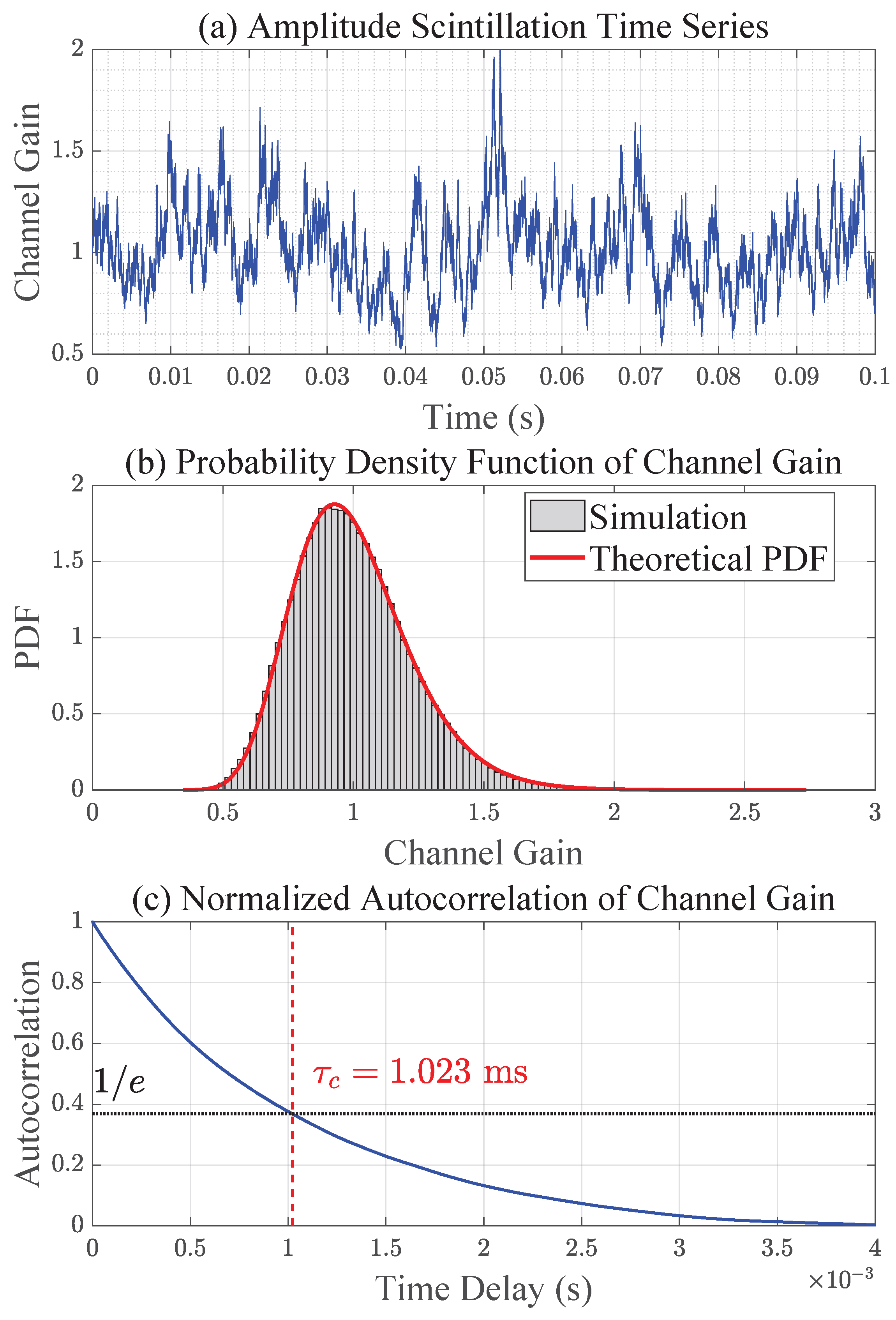
After confirming baseline behavior, the accuracy of the implemented turbulence and pointing models was validated.
Figure 6 presents amplitude scintillation results, including time-series evolution, PDF, and normalized autocorrelation. The simulated log-irradiance variance closely matches theoretical predictions, while the autocorrelation function exhibits the expected exponential decay, with the coherence time identified as the delay at which the correlation falls to
of its maximum value—a widely adopted criterion in fading channel analysis. Similarly,
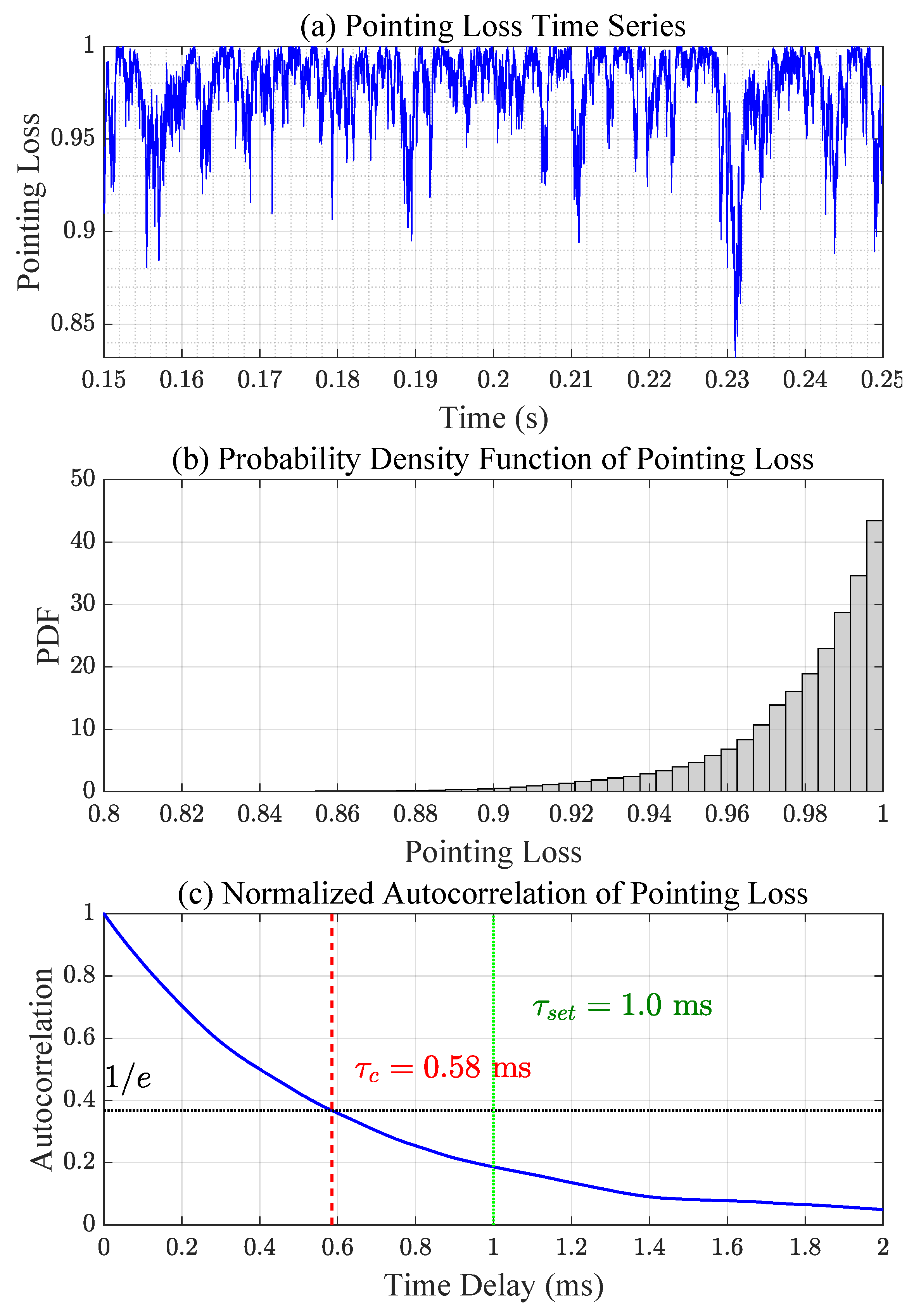
Figure 7 shows pointing error fading analysis, where the simulated distribution follows the Beta distribution model and the temporal correlation generated by the AR(1) process reproduces realistic jitter dynamics. In this case, the jitter process was generated with a Rayleigh-distributed baseline coherence time of 1 ms (
), but due to the nonlinear transformation from jitter to pointing-loss fading, the effective coherence time of
is observed to be approximately half that value.
We next evaluate system performance under the fading channel with
ms.
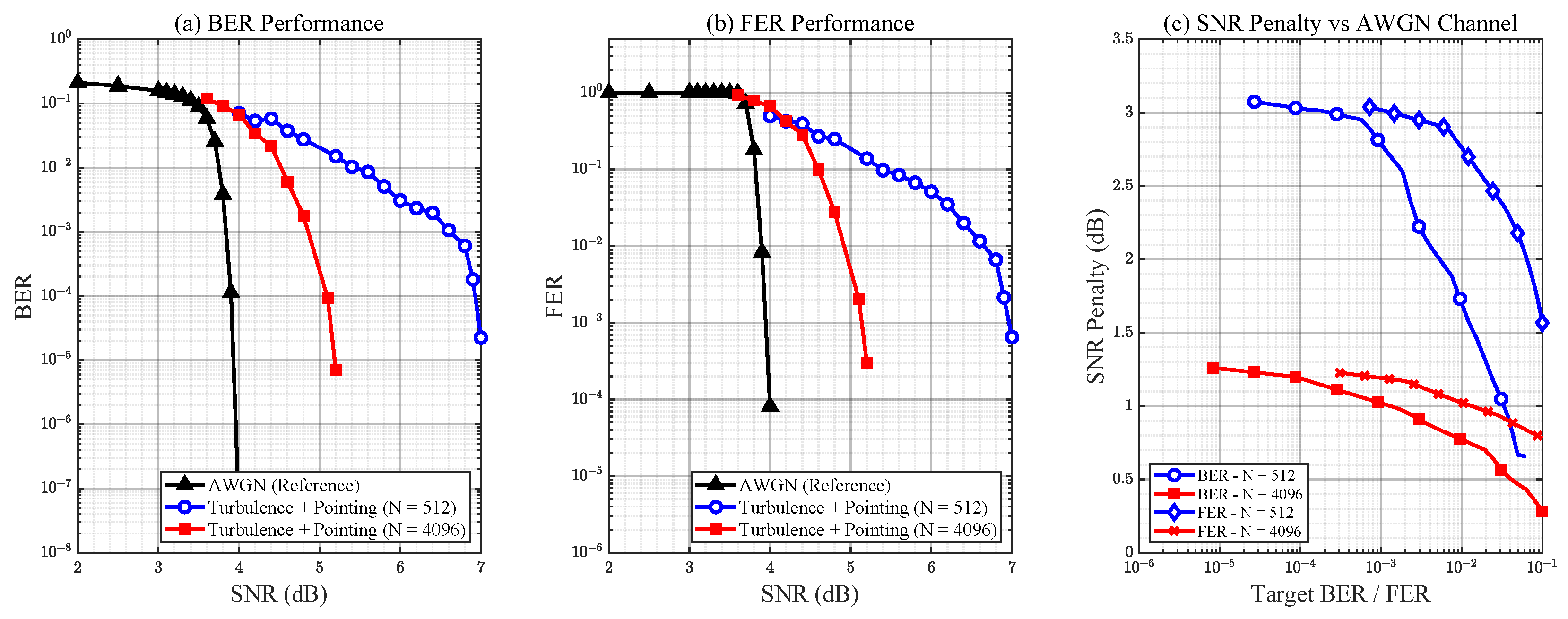
Figure 8 and
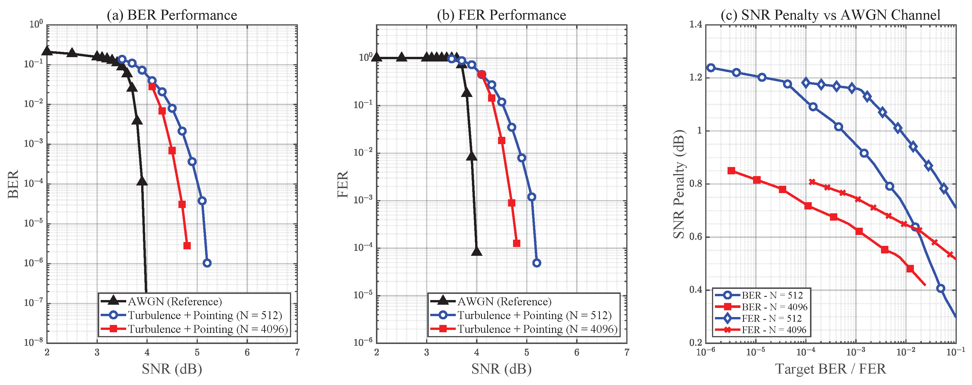
Figure 9 present the BER and FER performance of interleaver depths
and
, compared against the AWGN reference, for data rates of 1 Gbps and 100 Mbps, respectively. When turbulence and pointing errors are applied, the performance deviates substantially from the AWGN baseline. With a shallow interleaving depth of
, burst errors caused by temporally correlated fading extend across multiple codewords, leaving the LDPC decoder unable to fully recover the transmitted frames at high SNR values. Increasing the interleaving depth to
significantly improves performance by dispersing error bursts more effectively, thereby reducing the residual correlation seen by the decoder. Nevertheless, a noticeable performance gap relative to the AWGN case persists, indicating that deeper interleaving would further improve robustness.
At the lower data rate of 100 Mbps, overall performance improves compared to the 1 Gbps case for both interleaving depths. This improvement arises because, at lower data rates, each interleaved block spans a longer duration relative to the fading process. Consequently, consecutive codewords experience more variation across the fading cycle, which enhances the effectiveness of interleaving in mitigating burst errors.
These results highlight that interleaving depth must be carefully matched not only to turbulence variance and coherence time but also to the operating data rate. Because exhaustive Monte Carlo evaluation is computationally prohibitive—especially at long coherence times and deep interleaving depths—our ongoing work focuses on developing analytical tools to estimate the minimum interleaving depth as a function of fading severity, temporal correlation, and symbol rate.
Overall, the simulations show that CCSDS O3K-compliant systems are capable of maintaining robust performance under realistic LEO optical link conditions, provided that interleaving depth is carefully chosen. These results not only validate the rationale behind the standard’s emphasis on deep interleaving but also highlight its practical importance in mitigating the dominant impairments of turbulence and pointing jitter.
5. Conclusions
This paper presented an end-to-end CCSDS O3K-compliant simulation framework evaluated under realistically modeled atmospheric turbulence and pointing error conditions. The simulator implements the full CCSDS 142.0-P-1 chain, including LDPC coding/decoding and deep interleaving, combined with ITU-R-based turbulence modeling and an autoregressive pointing-error process.
Simulation results first validated the baseline performance of O3K LDPC codes under AWGN conditions, confirming the expected coding gains. When fading channels were introduced, the analysis demonstrated that temporally correlated turbulence and pointing errors generate severe burst errors that cannot be mitigated by coding alone. Deep interleaving was shown to be essential: increasing the interleaver depth from to significantly improved BER performance at a coherence time of 1 ms, illustrating the tradeoff between memory requirements and error resilience. These findings reinforce the design philosophy of the CCSDS O3K standard, particularly the inclusion of extremely deep interleaving to counter millisecond-scale fading, and provide practical reference values for configuring O3K-compliant optical links.
Future work will focus on analytically determining the appropriate interleaving depth for a given channel condition. The present results indicate that is not necessarily optimal, and because exhaustive simulations are computationally expensive, we are actively investigating analytical methods to estimate suitable interleaving depths as a function of channel fading strength and temporal correlation.

