Article

An Experimental Study on Pitot Probe Icing Protection with an Electro-Thermal/Superhydrophobic Hybrid Strategy

1
Department of Mechanical and Aerospace Engineering, University of Alabama in Huntsville, Huntsville, AL 35899, USA
2
Department of Aerospace Engineering, Iowa State University, Ames, IA 50011, USA
*
Author to whom correspondence should be addressed.
Aerospace 2025, 12(10), 862; https://doi.org/10.3390/aerospace12100862
Submission received: 31 August 2025 / Revised: 19 September 2025 / Accepted: 22 September 2025 / Published: 24 September 2025
(This article belongs to the Special Issue Deicing and Anti-Icing of Aircraft (Volume IV))

Abstract

A series of experiments were carried out to evaluate different anti-/de-icing approaches for a Pitot probe. Using the Iowa State University Icing Research Tunnel (ISU-IRT), this study compared the performance of a traditional electrically heated system with that of a hybrid concept combining reduced-power electrical heating and a superhydrophobic surface (SHS) coating. The effectiveness and energy efficiency of both methods were assessed. High-speed imaging was employed to capture the transient ice accretion and removal phenomena on the probe model under a representative glaze icing condition, while infrared thermography provided surface temperature distributions to characterize the unsteady heat transfer behavior during the protection process. Results indicated that, due to the placement of the internal resistive heating elements, ice deposits on the total pressure tube were easier to shed than those on the supporting structure. Relative to the conventional approach of maintaining a fully heated probe, the hybrid technique achieved comparable anti-/de-icing performance with substantially reduced power requirements—showing up to ~50% savings during anti-icing operation and approximately 30% lower energy use with 24% faster removal during de-icing. These findings suggest that the hybrid strategy is a promising alternative for improving Pitot probe icing protection.

1. Introduction

Inflight icing is a well-known weather hazard to the flight safety of aircraft in cold climates [1,2,3,4,5,6]. Airborne supercooled water droplets in the cloud would collide with the airplane’s frontal surfaces when it flew through an icing cloud layer, eventually turning into ice. While ice structures accumulated on airplane wings, propellers, or aero-engines have been found to cause serious performance degradation due to the icing-induced destruction to their streamlined profiles [7,8,9,10,11], ice accretion on flight sensors mounted over the exterior surfaces of an airplane such as Pitot probes and Angle of attack (AOA) senor can also result in false readings about the flight status, which directly threaten the flight safety of the airplane [12,13].
By measuring the difference between the static and dynamic pressure in the airflow, a Pitot probe, also referred to as the Pitot probe, is one of the most important sensors used to determine an airplane’s flying speed. Since the Pitot probes are placed close to the cockpit area, they are vulnerable to direct contact with airborne supercooled water droplets. This can result in ice formation or accretion over the Pitot probe, which can block the pressure measurement ports entirely or partially [12,14,15]. Pitot probe icing has been known to be highly risky starting from the early age of aviation [16] as the ice blockage of the pressure measuring ports would give pilots inaccurate readings. The misreading of the flight speed from iced Pitot probes would directly threaten flight safety by leading to the loss of control over the aircraft and even deadly aircraft crashes, such as the aviation tragedy of Air France 447 on 1 June 2009 [17] and Saratov Airlines Flight 703 on 2 February 2018 [18].
To address the safety issues of the Pitot probe under icing circumstances, several experimental and numerical studies have been carried out in recent years to examine Pitot probe icing phenomena. The properties of ice accretion across the surface of a Pitot probe under different icing circumstances were investigated numerically by Ozcer et al. [19]. Zhang et al. [20] reported a numerical investigation to characterize Pitot probe icing phenomena and found that ambient temperature would have the most significant influence on the icing-induced failure time of Pitot probes. More recently, an experimental study was conducted by Hu et al. [12,21] to investigate the dynamic ice accretion process on a Pitot probe model under various icing circumstances. The profiles of the accreted ice layers, the ice blockage ratio to the front probe port, and the total ice mass accreted on the Pitot probe model were used to quantify the ice accretion features under various icing situations
To mitigate the negative consequences of the aviation icing phenomenon, numerous anti-/de-icing systems/devices have been developed for aircraft icing mitigation [22,23,24,25]. Depending on the energy consumption required for the anti-/de-icing operation, icing protection systems may generally be classified into two groups: active and passive techniques. The active strategies refer to the systems depending on external energy consumption for the anti-/de-icing operation (e.g., electro-thermal heating or mechanical/ultrasonic-based surface deformation/vibration [26,27]), whereas the passive methods depend on hydro-/ice-phobic surface/coatings/materials to either delay or suppress ice accretion over airframe surfaces.
The most effective approaches to stop ice from forming or accumulating on aircraft surfaces are surface heating techniques. Commercial Pitot probes have already embedded electrothermal heaters as a typical method of preventing Pitot probe ice for decades. De Souza et al. [28] examined the conjugated heat transfer process associated with the transient thermal characteristics of heated aeronautical Pitot probes theoretically and experimentally. Jäckel et al. [14], otherwise, experimentally characterize the impacts of material qualities and interior composition on the icing process over a Pitot probe. Although it has been shown that electro-thermal surface heating systems may successfully prevent ice formation and accretion on Pitot probes, these systems are often configured to function at quite high temperatures (i.e., typically above 100 °C). The Pitot probe ice prevention would, thus, need a significant amount of energy, raising the aeroengines’ specific fuel consumption (SFC). The lifetime of Pitot probes would be limited by such a high required surface temperature, which would also significantly accelerate the oxidation of the probes’ inner and/or outer surfaces. Additionally, the electro-thermal systems’ ultra-high electric current requirements for Pitot probe icing prevention would increase the likelihood of the aircraft’s electric circuits failing.
To further enhance the anti-/de-icing efficiency, a novel hybrid method that combines electrothermal and superhydrophobic coatings has been proposed and widely studied in recent years [29,30]. Because of the benefits of cheap installation costs and minimal energy consumption, passive anti-/de-icing techniques employing hydro-/ice-phobic coatings/materials are being developed for usage as practical options for aircraft icing mitigation in recent decades [31,32]. Inspired by the outstanding self-cleaning capability of natural lotus leaves and goose feathers [33,34,35,36,37], extensive studies have been conducted to create superhydrophobic surfaces (SHS) through various approaches, on which water droplets bead up with a very large static contact angle (i.e., >150°) and drip off effortlessly when the surface is slightly inclined. In addition to their exceptional water repellency, SHS coatings have the ability to lessen the buildup of snow and ice on surfaces, which is one of their appealing uses. SHS coatings have been demonstrated to be very promising in postponing ice formation [38], even at temperatures as low as −30 °C [39]. A thorough analysis of the research work on creating different SHS coatings and their uses for ice reduction was given by Huang et al. [40].
Despite the fact that SHS coatings have been shown to offer a great deal of promise for aircraft icing prevention [41,42,43,44,45], one of the significant disadvantages of the passive approaches employing SHS coatings is their inability to suppress ice accretion in the regions close to the airframe’s leading edges [22,41,46,47]. Since the characteristics of SHSs are demonstrated to create minimal capillary/adhesion forces between the airframe surfaces and impinged water droplets or accumulated ice, these anti-/de-icing techniques rely on aerodynamic stress forces acting tangentially to the airframe surfaces to remove the impinged water droplets and accreted ice structures. Because the necessary aerodynamic shear forces close to the stagnation lines are negligible or vanish entirely, such passive techniques would fail at the stagnation lines [41,47]. The impinged supercooled water droplets would be rapidly collecting and freezing into ice around the leading edges as the stagnation lines close to the airframe’s leading edges typically have the highest water collection efficiency. More airborne supercooled water droplets would be impacted on the accreted ice structures’ surfaces directly rather than via the SHS coating after the ice structure began to accrete along the stagnation lines. An increasing number of ice structures would, hence, accrete quickly in the region near the airframe’s leading edges [41].
Thus, a system that uses minimal power to delaminate ice accretion in the crucial places, like airframe leading edges, and passive hydro-/ice-phobic coatings on other areas to reject ice accretion with the necessary aerodynamic forces applied by the boundary layer airflows over the airframe surfaces would be the perfect solution for preventing aircraft icing. A hybrid strategy that combines hydro-/ice-phobic coatings with restricted surface heating near the airframe leading edges has been developed to successfully remove the ice accretion from the airframe surfaces [45,47,48,49,50]. Gao et al. [47] showed that the hybrid anti-/de-icing technique would be able to preserve the whole airfoil surface ice-free under both rime and glaze icing circumstances, even if the electric heating element only covered 5% to 10% of the surface near an airfoil’s leading edge. The hybrid technique was also shown, by various researchers, to be able to keep the whole airfoil ice-free with much less power consumption (i.e., up to ~90% saving in the needed power consumption) than the traditional active strategy, which severely heated the vast airframe surface [21,47,51]. Furthermore, Hu et al. [50] demonstrated that the performance of the hybrid anti-/de-icing systems was more influenced by surface wettability than by icephobicity.
Most of the existing studies on hybrid anti-/de-icing methods were conducted via lab tests for either static icing or impingement icing scenario with low droplet impingement velocity or even without external flow. Very limited research can be found in the literature to study dynamic ice accretion process in relation to the aircraft inflight icing phenomena with higher supercooled water droplet impingement speed. It should also be noted that most of the previous studies on hybrid anti-/de-icing strategies were conducted using 2D airfoil models. The studies with more complicated aerospace geometries are necessary to further demonstrate the feasibility of the hybrid ant-/de-icing methods for realistic aerospace applications. In the present study, the effectiveness of a novel hybrid anti-/de-icing strategy, combining SHS coatings with electrothermal heating, to reduce the power consumption required for Pitot probe icing prevention was investigated parametrically.

2. Experimental Setup and Test Model

2.1. ISU-IRT Used for the Present Study

The experimental study was conducted in Iowa State University’s Icing Research Tunnel (ISU-IRT). The ISU-IRT features a test section that is 2.0 m long, 0.4 m wide, and 0.4 m high, as schematically seen in Figure 1. For data collection and viewing of the dynamic icing process, four optically transparent sidewalls were installed. The airflow circulating inside ISU-IRT is powered by a 30-hp motor, with the airflow speed up to 60 m/s in the test section. A refrigeration system powered by a 40-hp compressor is used to chill the environmental temperature inside ISU-IRT down to −25.0 °C. At the entrance of the ISU-IRT contraction section, nine pneumatic atomizer nozzles (IKEUCHI BIMV 8002, H. IKEUCHI & CO., LTD, Nishi-ku, Osaka, Japan) are installed to inject micro-sized water droplets (10~100 µm in droplet size with MDV ≈ 20 µm) uniformly into the freezing airflow [52]. The liquid water content (LWC) in the airflow may be changed between 0.2 and 5.0 g/m3 by adjusting the air pressure and water flow rate through the atomizer nozzles. In summary, the ISU-IRT can be used to replicate or simulate atmospheric icing phenomena over a wide range of icing circumstances, ranging from extremely dry rime to extremely wet glaze icing conditions. In recent years, the ISU-IRT has been used to study atmospheric icing phenomena for various engineering applications, including aircraft/aero-engine icing [10,53,54,55], wind turbine icing mitigation [47,56,57,58], and bridge cable and power transmission line anti-/de-icing [59,60,61].

2.2. The Pitot Probe Model Used for the Present Study

For the parametric evaluation of anti-/de-icing performance, a commercially available general aviation Pitot probe (PH 502 series, Aerosonic Corporation, Clearwater, FL, USA) was selected as the test article. As shown in Figure 1b, the probe features an “L”-shaped configuration comprising a total pressure tube (stagnation port) and an airfoil-shaped support structure, with overall dimensions of approximately 135 mm in length and 55 mm in width. The wedge-shaped total pressure tube leading edge is a cylinder with 88 mm in total tube length. While the inner tube diameter is 6.0 mm (i.e., Dinner = 16.0 mm), the outer tube diameter is measured to be 16 mm (i.e., Douter = 16.0 mm). The probe holder, which is used to support the Pitot probe on the airframe outer surface, was formed using symmetric airfoil shape with the chord length ranging from 38 to 54 mm. To remove any accumulated moisture or water that enters the Pitot probe, two drainage holes are positioned at the leading edge of the total pressure tube and the trailing edge of the probe holder [25].
For the anti-/de-icing function, an electro-thermal heating element is included inside the Pitot probe. A Direct Current (DC) power supply system was used to power the electro-thermal heater within the Pitot probe during the investigation. To calculate the electric power consumption for each run of anti-/de-icing operation, a multimeter was used to monitor the electric voltage and current applied to the electro-thermal heater. A comprehensive parametric study was conducted to ascertain the minimum power consumption necessary to guarantee the Pitot probe model functions in an ice-free state (i.e., without any ice structure covering its entire Pitot probe surface). The experiment started with a high electric power level delivered to the electrothermal. This allowed the Pitot probe model to have a very high surface temperature to prevent any ice accretion on the Pitot probe surface (i.e., staying in ice-free status). Then, the electric power level applied to the electro-thermal heater was reduced gradually until reaching the minimal power consumption value, or the point at which ice formations would begin to form on the Pitot probe surface.

2.3. Surface Coatings Used in the Present Study

Initially, in the experimental preparation stage, a thin layer of all-weather protective enamel coating (RustoleumTM, Flat Protective Enamel, Rust-Oleum, Vernon Hills, IL, USA) was sprayed on the Pitot probe model. The Pitot probe used in the present research is normally installed under the wings of general aviation airplanes, where the Pitot probe is believed to directly encounter the freestream flow without any flow distortion (Figure 2a). Since the original Pitot probe surface is coated with the hydrophilic nickel surface, the wettability of the enamel-coated surface was measured in terms of static contact angle (CAstatic). The wettability parameters, such as static contact angle, advancing and receding contact angle, are measured at the room temperature of T = 20 °C. The static contact angle (CAstatic) of water droplets on the enamel-coated surface is measured to be 65° (i.e., CAstatic ≈ 65°), while the corresponding value on the nickel-coated surface was CAstatic ≈ 60°. The wettability of the enamel-coated surface was found to be similar to that of the original nickel-coated Pitot probe model. Furthermore, the enamel-coated surface is selected also because it has an infrared (IR) emissivity of 0.96, which is almost the same as the IR emissivity of water and ice (i.e., 0.97) [62]. Therefore, the calibration procedure for IR measurements can be simplified significantly by applying a thin layer of enamel coating to cover the Pitot probe surface. An accurate quantification of the surface temperature distribution on the Pitot probe model from the acquired IR thermal images during the icing and anti-/de-icing processes can be guaranteed. Note that in order to show how well SHS coatings work to reduce the power needed for Pitot probe icing prevention, the enamel-coated Pitot probe surface served as the reference baseline in this investigation.
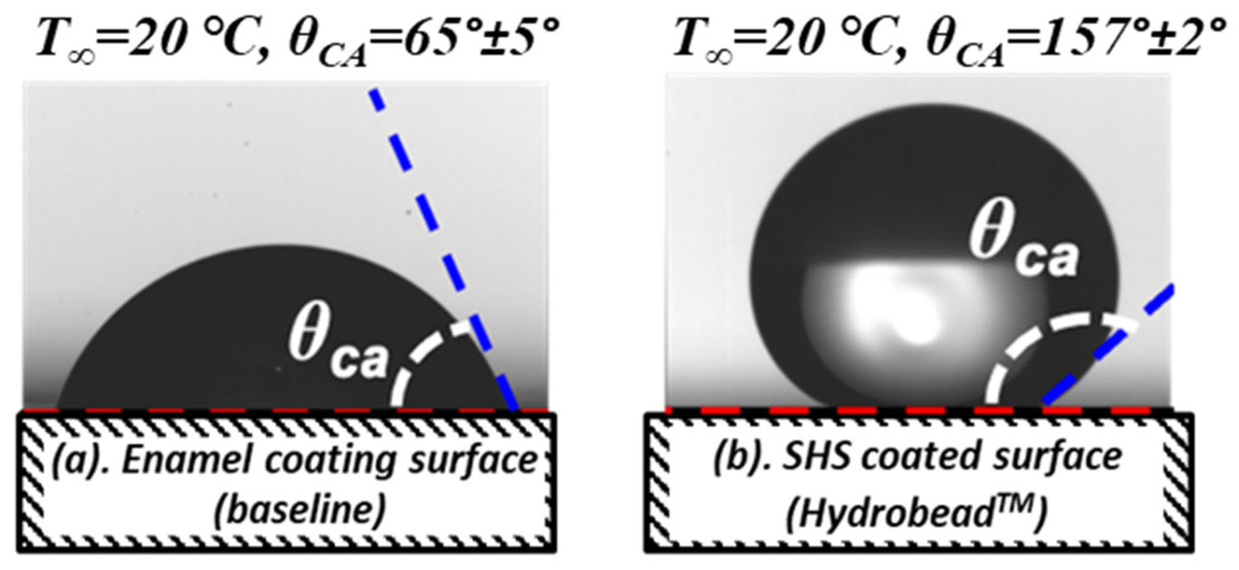
In order to compare the effectiveness of a hybrid anti-/de-icing system for Pitot probe icing protection, which combines a SHS coating for passive anti-/de-icing with active surface heating, to the conventional active strategies of brutally heating the Pitot probe surface, the surface of the Pitot probe model was also coated with a commercially available SHS coating (i.e., HydrobeadTM superhydrophobic coating, HydroBead, California, USA) in the current study. The wettability and icephobicity of the two surfaces under comparison (i.e., the enamel-coated surface and the SHS-coated surface) were assessed through a series of tests. For a quantitative comparison, Table 1 lists the observed wettability characteristics and the ice adhesion strength on the compared surfaces, while Figure 2 displays the typical obtained pictures of water droplets lying on the two surfaces for the static contact angle measurements. Note that the needle-in-the-sessile-drop approach, which is identical to that reported by Liu et al. [63] is used to place sessile water droplets on the two surface coatings under comparison to determine their wettability characteristics. A push-based technique akin to that employed in earlier research was utilized to quantify the ice adhesion strength data at −10.0 °C [57,58]. Table 1 also includes the mean and standard deviation values, which were determined using data from ten separate test trials.
As shown clearly in Figure 2 and Table 1, the static contact angle of the water droplet sitting on the Enamel-coated surface evidently indicates a hydrophilic surface, with the static contact angle θstatic ≈ 65° and the CA hysteresis (i.e., ∆θ = θadv − θrec) being ~ 60°. The measurement of the static contact angle of the water droplet on the SHS-coated surface is found to be θstatic ≈ 157° with the CA hysteresis being only ~ 5°. The contact angles on the SHS-coated surface were also verified at various temperatures down to −10 °C. The results show that the static contact angle is relatively stable, corresponding to the temperature change. The capillary forces that resist the water droplets sliding/rolling on the two compared tested surfaces were also estimated using the measured contact angles of the water droplets. The estimation is based on a theoretical model developed by Waldman et al. [46]. The capillary force for the water droplets on the SHS-coated surface would be significantly smaller than that on the Enamel-coated hydrophilic surface (i.e., becoming only about 4.0% of that on the Enamel-coated surface). It can also be seen clearly from the ice adhesion measurement that, while the ice adhesion strength on the Enamel-coated hydrophilic surface was found near 1.40 MPa, the corresponding value was only measured to be 110 KPa over the SHS-coated surface. The ice adhesion force for the SHS-coated surface is only about 8% of that on the Enamel-coated surface. It should also be noted that, while advanced hydro-/ice-phobic coatings with higher contact angles (<160°) and less ice adhesion strengths (~10 kPa) are under development, they can be used to further improve the performance of the hybrid anti-/de-icing system. While the development of such advanced hydro-/ice-phobic coatings is still at its early stage, the utilization of the advanced hydro-/ice-phobic coatings for realistic aerospace applications is of great interest for future research.

2.4. Icing Test Conditions and Measurement Systems

It is widely known that, depending on how quickly the latent heat of fusion can be released into the surrounding airflow, freezing of the supercooled water droplet on the model surface may occur entirely or partially [12]. Rime ice is created when all of the water gathered in the impingement region freezes upon impact during a dry regime. For a wet regime, only a portion of the impinged super-cooled water droplets would freeze in the impingement area to create glazing ice. The remaining unfrozen water would run back and freeze subsequently outside the droplet impingement area. When both rime and glaze ice properties are present at the same time, it is referred to as mixed ice.
In comparison to the rime icing scenario, glaze icing would deform the profiles of the ice accreting surface more severely, resulting in larger “ice feathers” and irregularly shaped “ice horns,” which would cause a greater degradation in performance compared to the rime icing scenario [12]. Additionally, it was stated that once ice accumulated as the transparent glaze ice, it would be far more challenging to remove. Therefore, in order to assess the effectiveness of the hybrid anti-/de-icing systems with the airfoil surfaces coated with SHS coatings, a typical severe glaze icing scenario was created in ISU-IRT. More precisely, for the present glaze icing experiments, the velocity of the incoming airflow is fixed at V = 40 m/s. The temperature and the liquid water content (LWC) level of the incoming airflow were set to be T = 5 °C and LWC = 2.0 g/m3, respectively. The Pitot probe model is mounted horizontally in the middle of the ISU-IRT test section. The angle of attack (AOA) of the pitot probe model was set to zero in relation to the incoming airflow (i.e., AOA = 0°) for all experiments.
Dynamic ice accretion and anti-/de-icing process over the Pitot probe surface were recorded using a high-speed imaging system (Photron FASTCAM MINI WX 100, Photron, Tokyo, Japan, with a maximum acquisition rate up to 25,000 fps and a spatial resolution of 2048 pixels by 2048 pixels). It is estimated that the recorded ice accretion pictures have a spatial resolution of around 9.0 pixels/mm. Simultaneously, surface temperature distributions of the Pitot probe model were measured using a high-speed infrared (IR) camera (FLIR A615, Teledyne FLIR LLC, Wilsonville, OR, USA). To enable thermal imaging during testing, an IR-transparent window (FLIR IRW-4C) was installed on the top panel of the ISU-IRT test section. According to Figure 1, the obtained IR thermal images used in this work have a spatial resolution of around 4.0 pixels/mm. Before beginning the ice accretion studies, the IR thermal imaging findings were calibrated at a number of specified low temperatures (i.e., down to −20 °C) using a calibration process akin to that outlined in Liu et al. [62]. The error of the IR thermal imaging measurement was determined to be ±0.25 °C within the measurement range of the current investigation. To confirm the findings of the IR thermal imaging experiment, two miniature K-type thermocouples were additionally slush-mounted to the bottom surface of the Pitot probe. A quantitative comparison between the thermocouple measurements and the IR thermography results demonstrated strong consistency.

3. Measurement Results and Discussions

3.1. Ice Accretion Process on the Pitot Probe Without Turning on the Electrothermal Heater

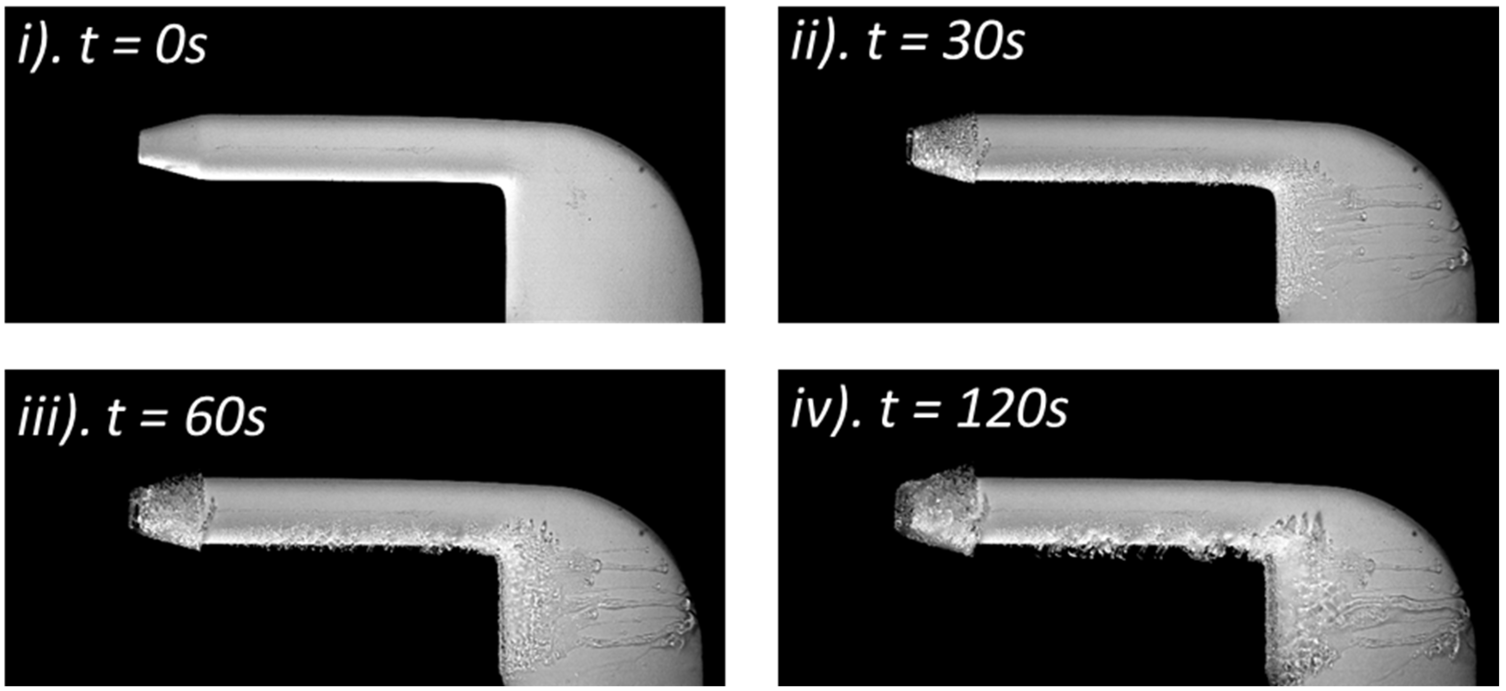
The test model was initially exposed to the typical severe glaze ice condition (i.e., V = 40 m/s, T =5 °C, and LWC = 2.0 g/m3) without turning on the electrothermal heater embedded inside the probe. Figure 3 shows typical snapshot images acquired by the high-speed imaging system to reveal the key features of the icing process (i.e., dynamic ice accretion, water runback, and complicated interactions of the multiphase flows) over the surface of the Pitot probe model. The surface of the test model is hydrophilic due to the Pitot probe being covered with a layer of protective enamel coating for this test case. This serves as the comparison baseline in the current study to assess how the SHS coating affects the ice accretion process over the Pitot probe’s surface.
As visualized clearly from the acquired ice accretion images given in Figure 3, when airborne supercooled water droplets impinged onto the surface of the Pitot probe model, ice accretion was found to occur primarily over the windward surfaces of the Pitot probe, i.e., on the wedge-shaped total pressure tube and close to the leading edge of the airfoil-shaped probe holder. As anticipated, the accreted ice structures displayed the typical features of a glaze ice accretion process, including a translucent and glassy look and clear evidence of runback ice rivulets across the Pitot probe surface. The following factors are thought to be responsible for the experimental observations: Similar to that reported in Liu and Hu [62], only a portion of the impinged supercooled water droplets would be frozen into a solid ice layer, with the remainder remaining in the liquid phase. This is because the relatively warm ambient temperature and higher LWC level under the glaze icing condition prevented the latent heat of fusion released during the glaze ice accretion process from dissipating efficiently. Driven by the boundary layer airflow over the test model, the unfrozen water droplets would clump together to create a thin water film and be able to move freely across the Pitot probe surface. The collected water mass was transported from the front surface of the test model (i.e., within the direct impinging zones of the airborne supercooled water droplets) to further downstream locations (i.e., reaching the further downstream region where the drain hole exists) by the formation of multiple rivulets. This was caused by the dynamic interactions of the complex multiphase flows between the impinged supercooled water droplets, frozen-cold airflow, and the wettability of the surface of the test model. The runback water was found to be cooled and eventually frozen into solid ice at further downstream locations because the incoming airflow was maintained at a frozen cold temperature (i.e., T = −5 °C) during the ice accretion experiment. This resulted in the formation of runback ice structures in the downstream regions far beyond the direct impinging zones of the airborne water droplets. The accreted ice layer was discovered to have a significantly greater coverage over the Pitot probe surface because of the runback ice structures’ creation; this even blocked the drain hole at the probe’s trailing edge.
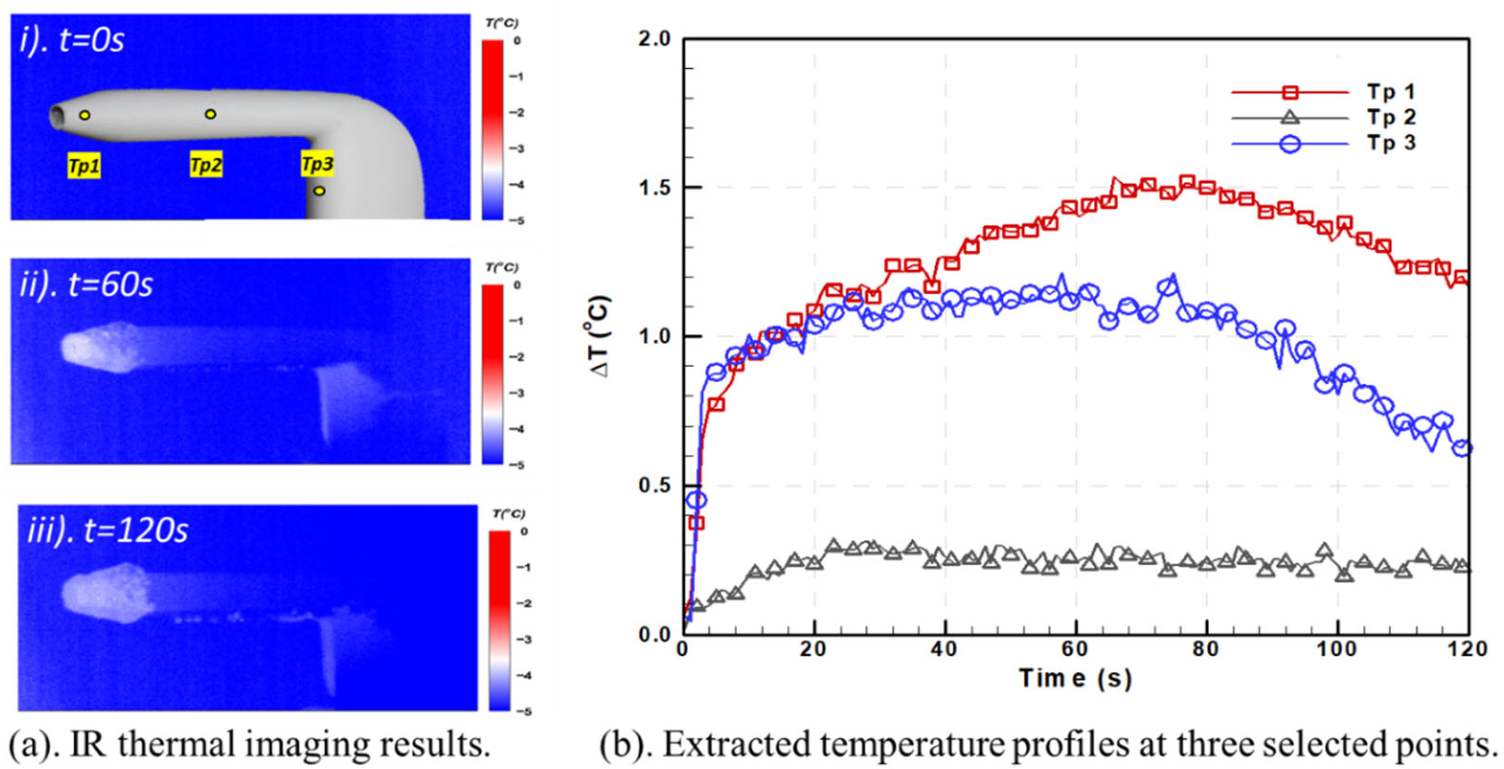
Figure 4 illustrates the associated IR thermal imaging data to reveal the transient variations in the surface temperature distributions on the Pitot probe model during the dynamic ice accretion process. The time evolution of the surface temperature change (i.e., ∆T = TpT; where Tp is the measured surface temperature, T is the incoming airflow temperature) at three selected locations on the Pitot probe surface (i.e., Tp1 is located on the front surface of the wedge-shaped total pressure port of the Pitot probe, Tp2 at the middle portion of the probe, and Tp3 at the probe holder) were extracted and plotted in Figure 4b based on the time sequences of the IR thermal imaging results. This can be used to more clearly and quantitatively reveal the unsteady heat transfer characteristics over the ice accreting surface of the Pitot probe model.
As revealed clearly from the IR thermal imaging results given in Figure 4a, when supercooled water droplets impinge on the Pitot probe model’s surface to initiate the ice accretion process (i.e., the solidification process), significant latent heat of fusion would be released due to the phase change in the impinged supercooled water droplets. This would result in a noticeable increase in the surface temperature of the Pitot probe model, particularly within the direct impingement zones of the airborne supercooled water droplets (i.e., on the frontal surface of the wedge-shaped total pressure port and near the leading edge of the airfoil-shaped probe holder. As illustrated more quantitatively in Figure 4b, the surface temperature on the front surface of the wedge-shaped total pressure port (i.e., at Tp1) would rise by up to 1.5 °C during the ice accretion experiment; the corresponding value was found to be approximately 1.1 °C close to the leading edge of the probe holder (i.e., at Tp3). The fact that the released latent heat of fusion would more easily dissipate from the metallic probe holder is believed to be strongly related to the lower temperature increase on the probe holder’s front surface (i.e., Tp3). Meanwhile, compared with the ice accretion near the total pressure tube, more mass of impinged supercooled water droplets on the holder part of the Pitot probe was found to be partially frozen and transported to further downstream locations in response to the more noticeable water runback on the probe holder surface. This would result in limited ice accretion and, thus, a smaller amount of the released latent heat of fusion. It can also be seen that, while no obvious ice structures were found to accrete at the side the total pressure tube (i.e., near Tp2), the slight temperature increase near the point of Tp2 (i.e., ~0.20 °C) is thought to be caused by heat conduction via the metallic body of the Pitot probe associated with the released latent heat of fusion due to with the ice accretion on the front surface of the total pressure cube. The higher temperature increases at the windward surface of the Pitot probe model also illustrated a higher collective coefficient of the supercooled water droplets, which makes these areas more vulnerable to the Pitot probe icing phenomenon.
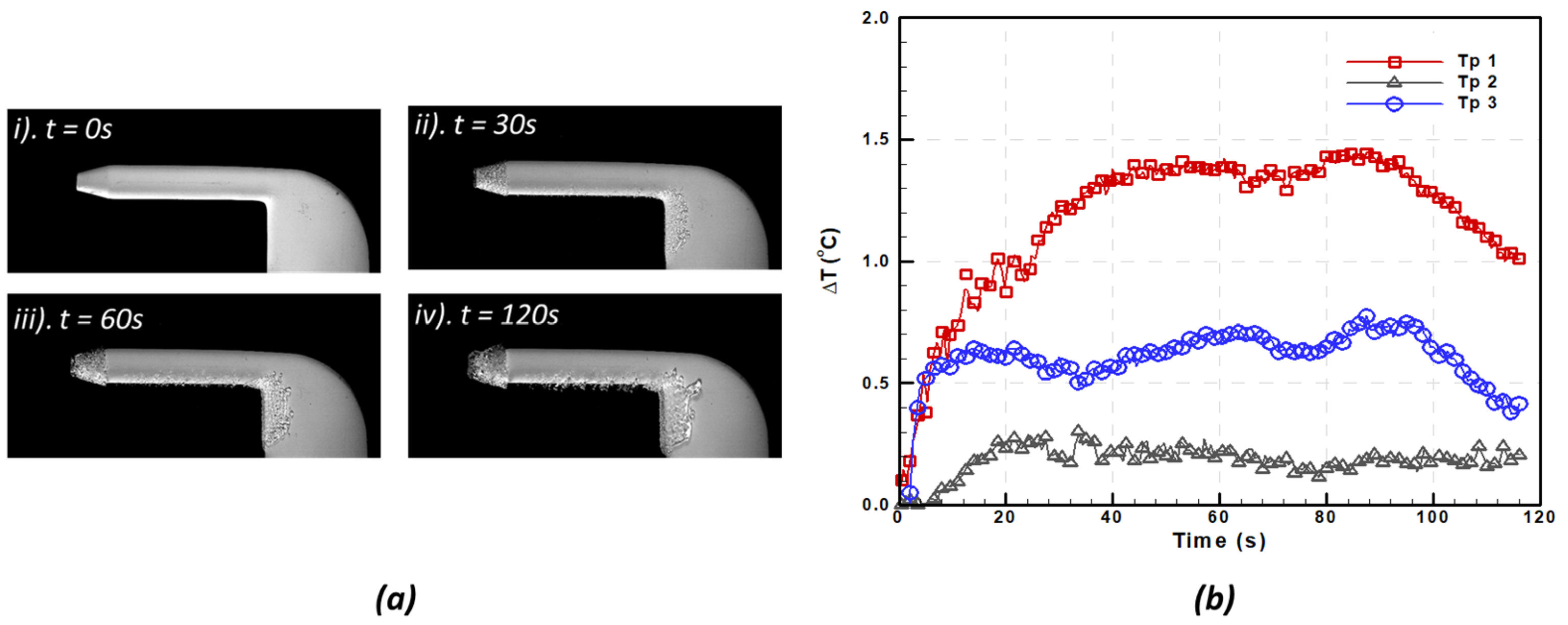
Figure 5 shows the acquired snapshot images to reveal the dynamic ice accretion process for the test case with the Pitot probe model coated with the SHS coating. It is evident that, in contrast to the baseline case (i.e., enamel surface) depicted in Figure 3, fewer ice structures were found to accrete on the SHS-coated surface of the Pitot probe, and no signs of water runback were observed over the SHS-coated model. Less ice accumulation and the disappearance of the runback ice rivulets over the SHS-coated surface of the Pitot probe model are thought to be caused by the following factors: (i) The identical supercooled water droplets would have lower wetting areas and significantly larger contact angles when they impinged onto the SHS-coated Pitot probe model, as shown in Figure 2. The aerodynamic shear forces exerted on the impinged water droplets and rivulets were substantially greater than those on the hydrophilic reference surface (i.e., the enamel-coated baseline), owing to the markedly increased droplet and rivulet heights. (ii) The capillary forces to restrain the motion of the water droplets/rivulets on the SHS-coated surface are only about 4% of those on the hydrophilic baseline surface (as given in Table 1). The impinged supercooled water droplets/rivulets would therefore run back over the SHS-coated surface considerably more quickly than those on the hydrophilic baseline surface if the Pitot probe model were subjected to the same incoming airflow. This would result in the impinged water droplets rapidly shedding from the SHS-coated surface of the Pitot probe model before they solidified into ice. As can be seen from the obtained ice accretion photos in Figure 5, the Pitot probe model’s surface did not exhibit any runback water rivulets or/and runback ice after applying the SHS coating.
Because there was not enough shear force to remove impinged water droplets near the stagnation point on the Pitot probe, ice structures were still observed to form on the frontal surface of the wedge-shaped total pressure cube and close to the leading edge of the airfoil-shaped probe holder (i.e., near the stagnation line), despite the fact that the ice coverage on the Pitot probe model was found to significantly decrease after the SHS coating was applied to the model surface. Consequently, it was discovered that as the ice accretion period grew, an increasing number of ice structures accreted across the Pitot probe model’s frontal surface. This highlights one of the major challenges with passive anti-/de-icing strategies using hydro-/ice-phobic coatings to reduce impact icing. Currently, removing the ice accretion from the region near the stagnation line is usually accomplished by using surface heating with electrothermal heaters to melt the ice structures accreted near the stagnation line, thereby reducing/removing the accreted ice structures from the surface in the vicinity of the stagnation line. As shown in Figure 5b, the IR thermal imaging system was also used to map the temperature distribution over the SHS-coated surface during the ice accretion process. Very similar features to those shown in Figure 4 were revealed from the IR thermal imaging results. The extraordinary water-repellency of the SHS coating successfully decreases the temperature increase rate as well as the maximum temperature during the solidification process. It is also worth noting that while the present study focused on typical glaze icing conditions, the other studies from our group had demonstrated the feasibility of using the superhydrophobic coating as well as the hybrid methods for successful anti-/de-icing operations under much colder and drier rime icing conditions with the ambient temperature reaching down to −15 °C [47,64].

3.2. Anti-/De-Icing Operations of the Pitot Probe with the Electrothermal Heater Turned on

As previously mentioned, commercial Pitot probes currently use electrothermal heaters as a common anti-/de-icing technique to prevent Pitot probe icing. In the present study, an experimental investigation was conducted to demonstrate the effectiveness of the electrothermal heater integrated into the Pitot probe for both the anti-icing and de-icing operations. While anti-icing refers to the prevention of any buildup of ice structures on a surface, de-icing denotes the case where ice has already formed on a surface, which is subsequently removed. An anti-/de-icing strategy is deemed effective when the ice-free condition is maintained during the impingement process (i.e., no ice accretion was found on the probe surface).
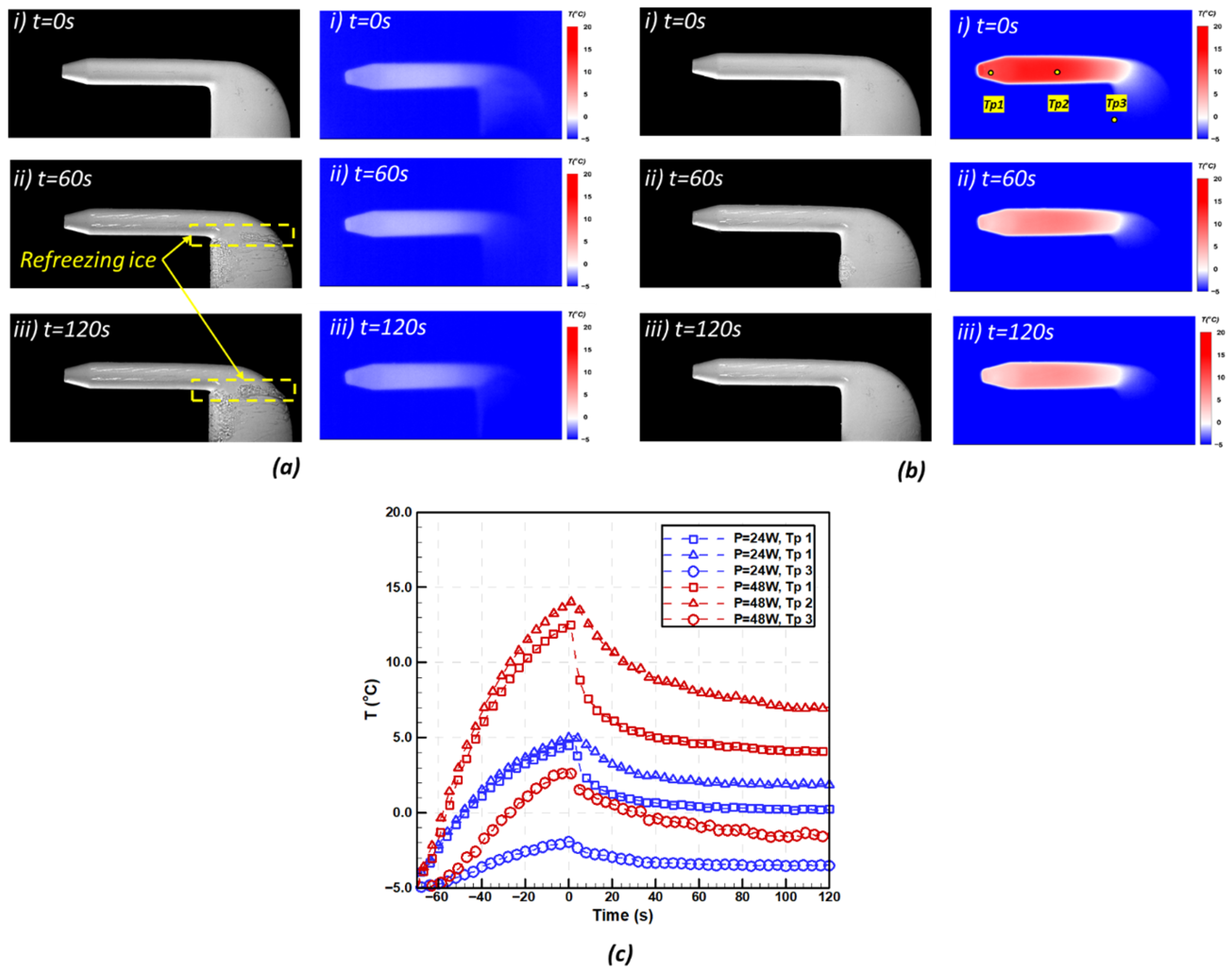
For the anti-icing operation, while the Pitot probe model was exposed to the same glaze icing condition (i.e., V = 40 m/s, T =5 °C and LWC = 2.0 g/m3), the electrothermal heater embedded inside the test model was activated to heat up the Pitot probe for about 60 s before the turning on the water spray system of the ISU-IRT to start the ice accretion experiment. The moment the water spray system is activated and the supercooled water droplets begin to be pumped into the test area is defined as the zero-time stamp. A parametric study was conducted to examine the effects of the electric power consumption on the effectiveness of the anti-icing operation. The electric power supplied to the electrothermal heater was adjusted from p = 0 (i.e., unheated case) to p = 48 W. Since the electrothermal heater was embedded near the total pressure port of the Pitot probe, the total pressure tube was found to become ice-free when the electric power applied to the electrothermal heater was greater than 9 watts (i.e., p > 9 W), while the probe holder of the Pitot probe became ice-free only when the applied electric power was greater than 48 watts (Table 2).
Figure 6 illustrates the acquired snapshot images and the corresponding IR imaging results during the anti-icing operation with: (i) successful anti-icing operation only for the total pressure tube (i.e., the electric power consumption of the electrothermal heater being p = 24 W), (ii) successful anti-icing operation for the entire Pitot probe (i.e., the electric power consumption to the electrothermal heater being p = 48 W). Since the electrothermal heater was positioned close to the total pressure tube’s entrance, as seen in Figure 6c, a significant rise in temperature (Tp1 and Tp2) was detected by the infrared system when the heater was turned on prior to the supercooled droplets impinging onto the Pitot probe model. The heating of the probe holder section relies on the heat conduction from the frontal part of the total pressure tube. When compared to the frontal portion of the Pitot probe, the temperature increase rate near the probe holder area (i.e., Tp3) experienced a mild increase.
When the power consumption of the electrothermal heater was set at 48 W (i.e., successful anti-icing operation for the entire Pitot probe), the surface temperature of the Pitot probe model increased above the water freezing temperature in a short range of time (i.e., ~ 10 s for total pressure tube and 40 s for the probe holder). The maximum temperature was 13 °C at the wedge of the total pressure tube (Tp1) and 14 °C at the side of the total pressure tube (Tp2), which corresponds to a total temperature increase (∆T) of ~20 °C. The temperature difference between Tp1 and Tp2 is believed to be caused by: (i) the embedded electrothermal heater is closer to Tp2 position where there is more space; (ii) since the wedge of the total pressure tube is facing the incoming flow, the heat transfer rate at the wedge of the total pressure tube (Tp1) is much higher compared to the side of the total pressure tube at downstream position which is parallel to the incoming flow. As the power consumption of the electrothermal heater decreased to 24 W, the temperature increase was relatively mild compared to the case of higher power consumption. It takes about twice the time to increase the temperature at the total pressure cube (Tp1 and Tp2) above the water freezing temperature. The maximum temperature is only around 5 °C at the Tp1 and Tp2 before the supercooled water impinges onto the Pitot probe surface. However, only a slight temperature increase is found at the probe holder due to the thermal input from the insufficient heat conduction. The temperature at Tp3 is continuously maintained below 0 °C before the spray system is turned on. Compared with the temperature increase at the total pressure tube (i.e., ∆T ≈ 10 °C for the case of p = 24 W and ∆T ≈ 20 °C for the case of p = 48 W ), the maximum temperature increase for the probe holder is less than half of those values (i.e., ∆T ≈ 3 °C for the case of p = 24 W and ∆T ≈ 7 °C for the case of p = 48 W). This indicates that the heating efficiency is much lower at the probe holder, which makes it more vulnerable to the icing conditions.
Due to heat transfer from the Pitot probe model surface to the impinged water droplet, a significant temperature reduction was seen at the beginning of the impingement in both cases when the supercooled water droplets struck the Pitot probe’s surface. After 60 s of the supercooled water droplets impingement, the temperature drop slowed and plateaued as a balanced state between the thermal input from the electrothermal heater, the thermal output from the heat transfer, and the impingement of the droplets was reached within the Pitot probe system. After the system reaches a balancing condition, the surface temperature of the total pressure tubes (Tp1 and Tp2 is maintained above the freezing point for the duration of the 120-s trials. Consequently, there is no ice buildup at the frontal part of the pitot probe (Figure 6a,b). All the impinged supercooled water droplets can be kept in the liquid state. The moisture inside the Pitot probe can finally be drained through the drain hole. The supercooled water droplet impinged onto the external surface was found to transport to a further downstream position as the liquid water run-back rivulets through the total pressure tube.
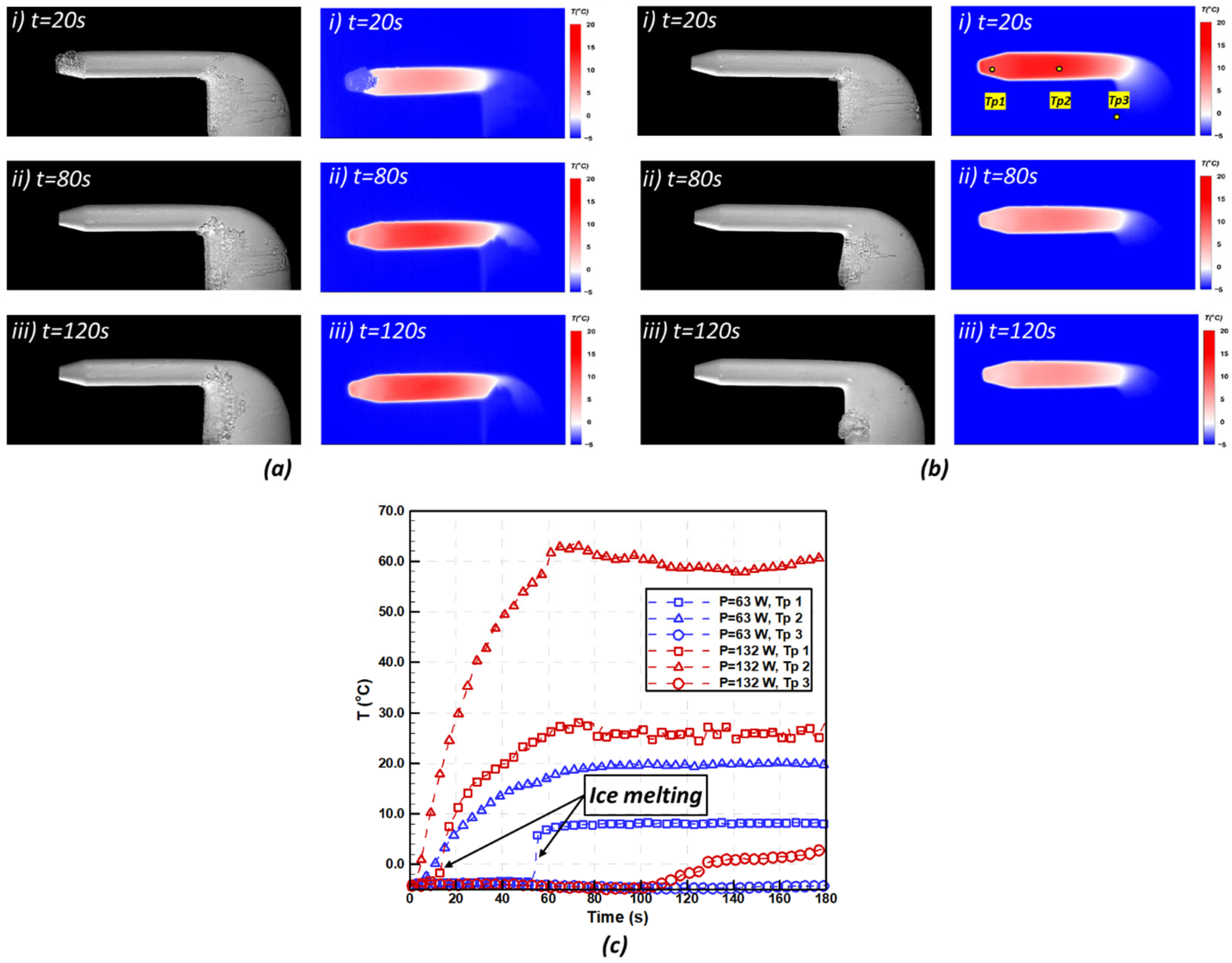
For the de-icing operation, the Pitot probe model was initially subjected to the wetted glaze icing condition for 30 s, allowing ice structure to form on the Pitot probe model. The Pitot probe was then heated to melt the ice using an electrothermal heater that was included inside the test model. The spray system was maintained operating during the entire de-icing process. The zero-time stamp is defined when the electrothermal heating system was turned on. Because melting the current ice layer requires more thermal energy input to compensate for the latent heat absorption during the liquification process of the existing ice structure, an experimental study indicates that deicing requires much greater power compared with the anti-icing process. The total pressure tube was found to become ice-free when the electric power applied to the electrothermal heater is greater than 48 W (i.e., p > 9 W), while the probe holder of the Pitot probe would become ice-free only when the applied electric power exceeded 96 W.
A successful de-icing operation for the entire pressure tube (i.e., the electric power applied to the electrothermal heater being p = 63 W) and a successful anti-icing operation for the entire Pitot probe (i.e., the electric power applied to the electrothermal heater being p = 132 W) are shown in Figure 7 in terms of obtained snapshot images, the corresponding IR imaging results, and the surface temperature plot for target locations. In contrast to the other temperature measurement locations, the temperature on the side of the total pressure tube (Tp2) rose more quickly, as seen in Figure 7c. At a power consumption of 132 W, the observed surface temperature at Tp2 rose beyond the freezing point in 5 s, while at a lower power consumption of p = 63 W, it took around 10 s. This led to the initial melting of the thin layer of ice that had collected on the side of the total pressure tube. After 20 s of heating, there was no ice layer visible on the side of the total pressure tube. With an ice layer covering the wedge region, the temperature at the total pressure tube’s leading edge (Tp1) was originally maintained at a constant level of T = 5 °C. A sudden jump was then observed, signifying the melting of the major ice block at the Pitot probe wedge area. After the first ice deposit was melted and removed from the total pressure tube, a significant temperature increase was subsequently discovered at point Tp1. A plateau was also discovered following the establishment of the new thermal balance between the supercooled water droplet impingement, heat transfer, and electrothermal heating. While it took a total of 50 s for the ice layer to totally melt/shed from the leading edge of the total pressure tube, with a power consumption of p = 63 W, the removal time of the Pitot probe leading-edge ice was just 10 s when the power consumption was increased to 132 W.
As shown in Figure 6c, the probe holder’s heating efficiency is substantially lower than that of the entire pressure tube because the thermal energy needed for the de-icing operation is heat conduction from the frontal section of the tube. As a result, the Pitot probe requires much higher power consumption and overall time to accomplish a good de-icing procedure. With a power consumption of p = 63 W, the ice structure, particularly the ice structure at the leading-edge of the Pitot probe, was not properly removed during the whole de-icing procedure, as seen in Figure 7a. This suggests that there was not enough thermal energy input to completely melt the ice structure. The thickness of the ice layer at the leading edge of the probe holder increased as a result of the continuous impingement of supercooled water droplets. Thus, the measured temperature at point Tp3 was the temperature of the ice structure, which is constantly around freestream temperature (i.e., T = 5 °C). Compared with the thick ice layer at the leading edge of the probe holder, both the thickness and total amount of the ice rivulet due to the partially freezing natural under the glaze ice condition are minimum and easier to melt. The run-back ice was found to be completely eliminated after the electrothermal heater was turned on for 120 s. When the power consumption is adjusted to p = 132 W, the maximum power of the current Pitot probe model, the de-icing process is visualized in Figure 7b. The thin run-back ice rivulets were found to be totally removed after the heating system had been activated for 80 s, and the major portion of the ice structure at the leading edge of the probe holder was removed at the time stamp of 120 s. As also illustrated in Figure 7c, a temperature rise at point Tp3 was found once the ice structure was removed from the surface. With the surface temperature at the probe holder increasing above the freezing point, the ice structure is completely removed after 160 s when the heater is activated.

3.3. Comparison of the Anti-/De-Icing Performance Between Two Strategies

In order to prolong the Pitot probe’s lifespan, it is necessary to reduce the power consumption during anti-/de-icing operation and increase the anti-/de-icing efficiency. A hybrid strategy, which combines the conventional electrothermal heating strategy with the SHS coating strategy, was proposed and applied to the Pitot probe model. The anti-/de-icing effectiveness and efficiency were compared parametrically for the two strategies. The procedure of anti-/de-icing operation was the same as the baseline case (conventional heating strategy in Section 3.2) under the glaze ice condition (i.e., ∆T ≈ 10 °C for the case of p = 24 W and ∆T ≈ 20 °C). While the minimum power requirement for successful anti-icing operation for both the total pressure tube and the probe holder was found through the comprehensive parametric experiments, the ice shedding time was also recorded during the de-icing operation to verify the anti-/de-icing efficiency.
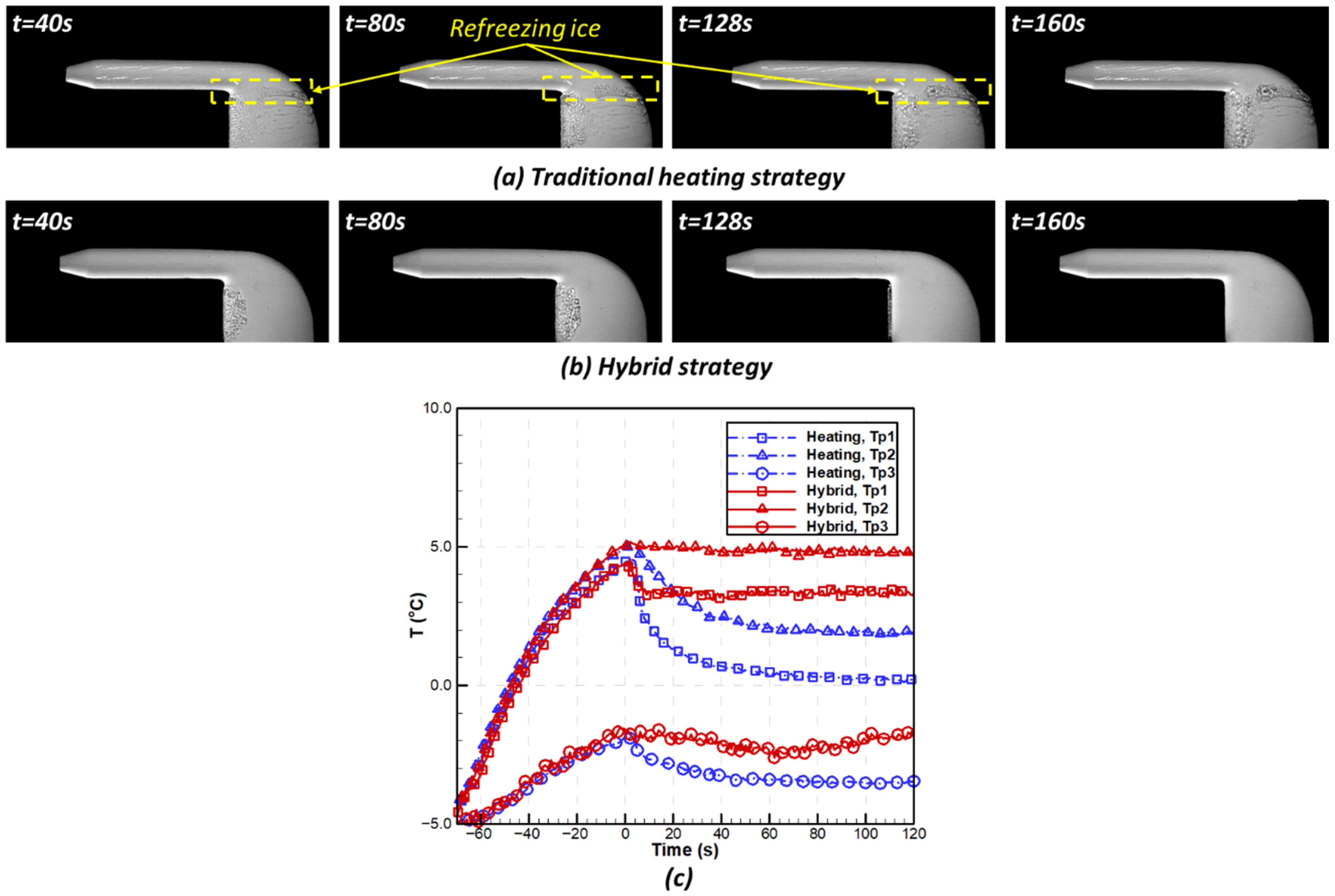
Figure 8 presents the anti-icing performance of the conventional electrothermal strategy and the hybrid strategy at a power input of p = 24 W. The conventional electrothermal heating approach was effective in preventing ice formation only at the total pressure port, leaving the probe holder susceptible. In contrast, the hybrid strategy successfully inhibited and removed ice accumulation on both the total pressure port and the probe holder under the same power conditions.
As revealed in Figure 8a, the total pressure tube operating under the conventional strategy showed obvious water run-back rivulets, which would be refrozen into the ice structure once they reached the probe holder position with insufficient thermal energy input. The refreezing of the water film led to increased ice accumulation at the probe holder trailing edge. However, no water run-back can be found on the SHS for the Hybrid strategy. The causes that contribute to the absence of the run-back rivulets are: (i) the high contact angle prevents the impinged supercooled water droplet from forming a water film, all the water on the Pitot probe surface exists as semi-spherical droplets; (ii) the extremely low capillary force results in effortless removal of the water droplets from the Pitot probe surface. Therefore, when employing the hybrid approach, no refreezing ice is observed on the Pitot probe. At the initial time of the anti-icing operation, the ice structures were observed at the probe holder leading edge for both strategies due to the insufficient thermal energy input to either prevent the ice formation or a lack of enough shear force at the stagnation line to remove the existing ice layer. The application of the Hybrid strategy successfully prevents the formation of the run-back rivulets. Furthermore, the first shedding of the leading-edge ice structure was found in the hybrid case after 128 s when the electrothermal heater was turned on. The remaining ice structure was found to shed from the surface after 160 s of hybrid anti-icing operation due to the continuous heat conduction to increase the surface temperature and low ice adhesion of the SHS-coated surface.
As shown in Figure 8c, the temperature increment prior to the spray system being activated for both strategies was the same due to the same power consumption. The temperature at the total pressure tube (Tp1 and Tp2) easily reached above the freezing point, and the temperature at the probe holder (Tp3) did not exceed the freezing point at the time when the supercooled water droplet impinged onto the Pitot probe surface. At the initial time when the spray system was turned on, an abrupt reduction in temperature was seen at location Tp1, indicating heat transfer from the Pitot probe surface to impinged droplets. As for the traditional heating strategy, the surface temperature at Tp1 continued to decrease for 100 s and reached a balanced state near the freezing point. The temperature at the Tp2 also experiences a decrease because the liquid water film is transported from the Pitot probe leading edge to further downstream positions. With the SHS coating on the Pitot probe, a portion of the supercooled water droplets tend to bounce off after colliding with the Pitot probe surface. It will cause the temperature at Tp1 to achieve a balancing condition considerably more quickly (i.e., within 10 s after impingement) at a high stable temperature of 3 °C. Additionally, as the water droplets are more easily removed and shed from the total pressure tube and no run-back rivulets were seen, there is no discernible temperature loss for Tp2 in the hybrid instance.
The results of the parametric study for anti-icing operations are summarized in Table 2, where successful and failed operations are indicated by “Success” and “Fail,” respectively. Because the electrothermal heater is embedded near the leading edge of the total pressure tube, heating is most effective in this frontal region, making anti-icing performance largely governed by thermal effects. Consequently, both the conventional thermal strategy and the hybrid strategy exhibit similar anti-icing effectiveness and efficiency for the total pressure tube, with a minimum required power of p = 9 W and failure below this threshold. In contrast, heating the probe holder depends on heat conducted from the total pressure tube, and the superhydrophobic properties of the SHS coating significantly enhance anti-icing performance in this area. As shown in Table 2, the hybrid strategy achieves up to 50% power savings under severe glaze icing conditions: the probe holder remained ice-free at a minimum power of p = 24 W using the hybrid approach, compared with p = 48 W required for the conventional heating strategy.
Figure 9 illustrates the de-icing performance of the conventional electrothermal strategy (Figure 9a) and the hybrid strategy (Figure 9b) at a power input of 62 W. As shown in Figure 9a, the conventional system rapidly melted the ice on the total pressure tube within 60 s after activation. However, due to insufficient heating at the probe holder and continued impingement of supercooled droplets, only partial melting occurred near the probe holder, resulting in run-back ice rivulets. With the hybrid strategy, the de-icing efficiency at the total pressure tube remained comparable to that of the conventional method, while the ice on the probe holder was fully removed under the same power input. This enhanced de-icing performance is attributed to two factors: (i) the SHS coating reduces overall ice accumulation, effectively limiting run-back ice, and (ii) the lower capillary and ice-adhesion forces on the SHS increase the likelihood that ice structures can be removed by the aerodynamic boundary layer flow.
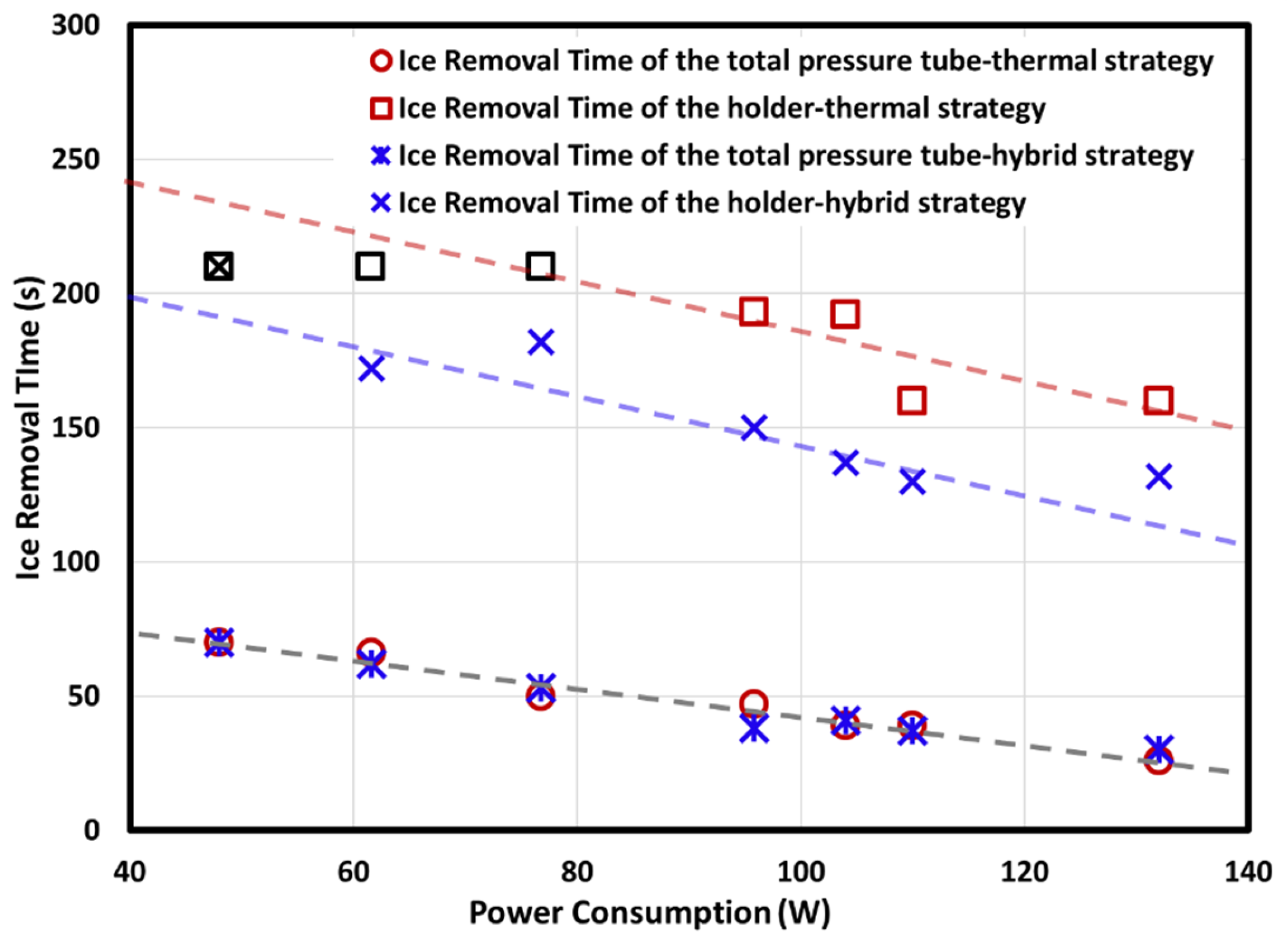
Figure 10 presents the results of the parametric study on ice removal time for the two strategies under various de-icing power inputs. Black markers indicate unsuccessful de-icing operations, while red and blue markers correspond to the time required for complete ice removal from the Pitot probe surfaces. Ice shedding time for both strategies decreased approximately linearly with increasing power. For the total pressure tube, both strategies exhibited similar performance at each tested power level, likely because electrothermal heating dominates the de-icing process in this region. In contrast, for the probe holder, the hybrid strategy reduced the minimum power required for successful ice removal by approximately 30%, and the ice removal time was shortened by about 24% due to the lower capillary and adhesion forces of the SHS.
Notably, the hybrid anti-/de-icing approach offers substantial power savings, enabling lower surface temperatures and reduced energy consumption during operation, which can help extend the service life of the Pitot probe. Furthermore, the current probe heating system layout remained unchanged due to design constraints; with an optimized heating configuration, further reductions in energy consumption are expected.

3.4. Benefits and Limitations of the Hybrid Anti-/De-Icing Methods

The measurement results given above have demonstrated enormous advantages of utilizing the hybrid anti-/de-icing strategy, which combines the electrothermal heating with minimized applied heating power and superhydrophobic coatings, over the conventional method relying on surface heating only for Pitot probe icing protection. More specifically, the benefits of the hybrid anti-/deicing methods for Pitot probe icing protection can be summarized as follows:
Energy saving for anti-icing operation. Under adverse icing weather conditions, anti-icing systems of Pitot probes are required to be activated throughout the entire duration of the flight envelope. Based on the measurements given in Table 2, for a flight case that requires a power output of ~150 W for a conventional thermal-based anti-icing system, the hybrid anti-icing system would only require a power consumption of ~75 W to achieve the same effectiveness for Pitot probe icing protection, leading to about 50% energy saving for the anti-icing operation. This will result in 0.075 kWh of power saving for each Pitot probe per hour of aircraft flight time. Considering the scenario that the electronics of a general aviation aircraft are usually driven by an alternator in a power range between 1 and 5 kW. Even for the scenario with only one Pitot probe installed on the aircraft, the Pitot probe with a hybrid anti-/de-icing system will provide a power saving between ~1.5% to ~7.5% of total electrical power generated on the aircraft.
Shorten the time for the de-icing process. Encountering unexpected icing conditions would require a full removal of ice accretion on Pitot probes rapidly by switching on the de-icing mode. In the present study, while the total pressure port can be ice-free within one minute, it takes more than 3 minutes to clear the ice formation on the entire Pitot probe when relying on the electrical thermal system only. By applying the hybrid strategy, the required de-icing time for the Pitot probe was found to be shortened by about 30%. This will lead to a faster de-icing operation to ensure the Pitot probe provides correct readings during the entire flight duration, even when encountering unexpected icing clouds.
Extended the lifetime of Pitot probes. The surface temperature of the Pitot probe can reach more than 150 °C when operating at the full power mode when using the conventional electrothermal system for ant-/de-icing operation. Such a high temperature can cause the oxidation of the protective coatings of the Pitot probe and lead to the following rusting on both the external and internal surfaces. As revealed from the measurements given above, the hybrid ant-/de-icing strategy not only required a lower power consumption of the Pitot probe icing protection but also reduced the operation temperature of the Pitot probe substantially. The lower operation temperature would greatly delay the oxidation process of the protective coatings over the surfaces of the Pitot prob, preventing the rusting, thereby, extending the lifetime of the Pitot probe.
It should be noted that the SHS coating used for the hybrid anti-/de-icing strategy relies on micro-/nano-scaled textures generated on the protected surface to repel the impinging supercooled water droplets for the anti-/de-icing operation. There are concerns about the degradation of the SHS coatings caused by: (i) rain erosion effects due to long-time impingement of the water droplets and other airborne particles; (ii) corrosion effects due to contacting other chemicals such as de-icing fluids; and (iii) exposure to extreme UV conditions. In the present study, while the contact angles of the SHS coating were measured after each test, no noticeable degradation of superhydrophobicity for the SHS coating is found due to the limited duration of the experiments.
It is worth noting that long-time impinging of water droplets will lead to substantial degradations of the SHS coatings. Zhang et al. [65] conducted an experimental investigation to evaluate the variations in the surface wettability and ice adhesion strength on a SHS-coated surface before and after undergoing continuous impingement of water droplets (i.e., rain erosion effects) at relatively high speeds (i.e., up to ~100 m/s). While the large and/or sharp roughness/texture structures on the SHS-coated surface were found to be grinded away rapidly due to the continuous impinging of airborne droplets, onto the test surface, both the static and receding contact angles on eroded SHS-coated surface were found to decrease exponentially as the duration of the rain erosion experiment increases. More recently, Zhang et al. [42] conducted a comprehensive investigation to examine the detrimental effects of deicing fluids on the performance of SHS coatings for aircraft icing mitigation. They found that spraying Type-1 deicing fluid for ground deicing would have only very minor effects on the performance of the SHS coatings. However, spraying Type-IV deicing fluid onto airframe surfaces would degrade the performance of the SHS coatings significantly and totally deteriorate the effectiveness of the SHS coatings for aircraft icing mitigation.
The degradation of the SHS coatings will lead to performance degradation of the hybrid anti-/de-icing method for Pitot Probe icing protection. With the continuous degradation of the SHS coatings, the required electric power to prevent/remove ice structures accreted over the surface of the Pitot probe would increase gradually in order to keep the surface of the Pitot probe ice-free. With the rapid progress of material science and surface engineering in recent years, advanced SHS coatings/materials with better erosion-resilient and corrosion-resistant performances are being developed [66,67,68]. The advanced SHS coatings/materials have been demonstrated to be much more durable in comparison to conventional SHS coatings [67,68]. Comprehensive investigations will be conducted in the near future to explore the effectiveness of utilizing the advanced SHS coatings/materials for Pitot probe icing protection.

4. Conclusions

A comprehensive experimental investigation was conducted to assess the effectiveness and power-saving efficiency of a novel hybrid anti-/de-icing approach by properly integrating minimized electrothermal heating with a superhydrophobic (SHS) coating for Pitot probe icing protection, in comparison to conventional active anti-/de-icing method of relying on brutal electrothermal heating and a passive method using SHS coating only. The experimental study is conducted in the Iowa State University Icing Research Tunnel (ISU-IRT) with a commercially available aircraft Pitot probe exposed to typical glaze icing conditions with V = 40 m/s, T = −5 °C, LWC = 2.0 g/m3. During the experiments, while a high-resolution imaging system was used to record the dynamic ice accretion and anti-/de-icing processes, a high-speed infrared (IR) thermal camera was utilized to map the surface temperature distributions of the Pitot probe to quantify the unsteady heat transfer characteristics associated with ice accretion and anti-/de-icing operation.
The results show that ice predominantly accumulates at the entrance of the total pressure tube and along with the probe holder. Under severe glaze icing conditions, the interplay between impinging supercooled droplets and the freezing boundary layer leads to run-back ice rivulets covering the probe holder. Application of the SHS coating markedly reduces these rivulets, although ice formation near the total pressure port is largely unaffected by the surface coating.
Because the electrothermal heater is embedded near the total pressure tube, temperature rises rapidly at the frontal region when powered, whereas the probe holder relies on heat conducted from this region. Consequently, anti-/de-icing efficiency is higher at the total pressure tube than at the probe holder, and insufficient heating at low power levels easily results in ice accumulation at the holder. Compared with anti-icing, de-icing requires significantly more thermal energy to overcome the latent heat of melting.
Overall, the hybrid strategy was found to achieve comparable anti-/de-icing performance to conventional full-power heating while consuming considerably less energy—up to ~50% power savings during anti-icing and ~30% energy reduction with 24% shorter ice removal time during de-icing—highlighting its promise for efficient Pitot probe icing mitigation.

Author Contributions

H.H. (Haiyang Hu): Methodology, Investigation, Visualization, Formal Analysis, Validation, Writing—Original Draft; F.A.-M.: Investigation, Visualization, Formal Analysis; H.H. (Hui Hu): Conceptualization, Methodology, Formal Analysis, Writing—Review and Editing, Supervision, Project Administration, Funding Acquisition. All authors have read and agreed to the published version of the manuscript.

Funding

This work was partially supported by the Nation Research Foundation of Korea (NRK) grant via the Global Research Center for Aircraft Core Technology (Global ACTRC) at Gyeongsang National University (GNU) funded by the S. Korea government (MSIT) (RS-2024-00397400). The support from National Science Foundation (NSF) with grant number of CBET-2313310 is also acknowledged.

Data Availability Statement

The original contributions presented in this study are included in the article. Further inquiries can be directed to the corresponding author.

Conflicts of Interest

The authors declare no conflicts of interest.

References

  1. Bragg, M.B.; Gregorek, G.M.; Lee, J.D. Airfoil Aerodynamics in Icing Conditions. J. Aircr. 1986, 23, 76–81. [Google Scholar] [CrossRef]
  2. Campbell, S.E.; Broeren, A.P.; Bragg, M.B. Sensitivity of Aircraft Performance to Icing Parameter Variations. J. Aircr. 2007, 44, 1758–1760. [Google Scholar] [CrossRef]
  3. Cebeci, T.; Kafyeke, F. Aircraft icing. Annu. Rev. Fluid. Mech. 2003, 35, 11–21. [Google Scholar] [CrossRef]
  4. Ueno, K.; Farzaneh, M. Linear Stability Analysis of Ice Growth under Supercooled Water Film Driven by a Laminar Airflow. Phys. Fluids 2011, 23, 042103. [Google Scholar] [CrossRef]
  5. Fortin, G.; Laforte, J.L.; Ilinca, A. Heat and Mass Transfer during Ice Accretion on Aircraft Wings with an Improved Roughness Model. Int. J. Therm. Sci. 2006, 45, 595–606. [Google Scholar] [CrossRef]
  6. Waldman, R.M.; Hu, H. High-Speed Imaging to Quantify Transient Ice Accretion Process over an Airfoil. J. Aircr. 2016, 53, 369–377. [Google Scholar] [CrossRef]
  7. Liu, Y.; Li, L.; Chen, W.; Tian, W.; Hu, H. An Experimental Study on the Aerodynamic Performance Degradation of a UAS Propeller Model Induced by Ice Accretion Process. Exp. Therm. Fluid. Sci. 2019, 102, 101–112. [Google Scholar] [CrossRef]
  8. Li, L.; Liu, Y.; Tian, L.; Hu, H.; Hu, H.; Liu, X.; Hogate, I.; Kohli, A. An Experimental Study on a Hot-Air-Based Anti-/de-Icing System for Aero-Engine Inlet Guide Vanes. Appl. Therm. Eng. 2020, 167, 114778. [Google Scholar] [CrossRef]
  9. Liu, Y.; Kolbakir, C.; Hu, H.; Hu, H. A Comparison Study on the Thermal Effects in DBD Plasma Actuation and Electrical Heating for Aircraft Icing Mitigation. Int. J. Heat. Mass. Transf. 2018, 124, 319–330. [Google Scholar] [CrossRef]
  10. Tian, L.; Li, L.; Hu, H.; Hu, H. Experimental Study of Dynamic Ice Accretion Process over Rotating Aeroengine Fan Blades. J. Thermophys. Heat. Trans. 2023, 37, 353–364. [Google Scholar] [CrossRef]
  11. Tian, L.; Hu, H.; Veerakumar, R.; Hu, H. Ice Accretion Characteristics on Rotating Aeroengine Fan Blades. Exp. Therm. Fluid. Sci. 2024, 155, 111181. [Google Scholar] [CrossRef]
  12. Hu, H.; Al-Masri, F.; Tian, L.; Hu, H. Experimental Study of Dynamic Icing Process on a Pitot Probe Model. J. Thermophys. Heat. Trans. 2023, 37, 632–643. [Google Scholar] [CrossRef]
  13. Han, N.; Siddique, M.A.; Zhang, Z.; Tian, L.; Hu, H.; Hu, H. A Flight-Testing Campaign to Examine Inflight Icing Characteristics and Its Effects on the Flight Performance of an Unmanned-Aerial-Vehicle. Cold Reg. Sci. Technol. 2023, 207, 103775. [Google Scholar] [CrossRef]
  14. Jäckel, R.; Gutiérrez Urueta, G.L.; Tapia Rodríguez, F.; Monreal Jiménez, C. Numerical and Experimental Characterisation of an Aeronautic Pitot Probe. Aeronaut. J. 2019, 123, 890–911. [Google Scholar] [CrossRef]
  15. Ayra, E.S.; Sanz, Á.R.; Valdés, R.A.; Comendador, F.G.; Cano, J. Detection and Warning of Ice Crystals Clogging Pitot Probes from Total Air Temperature Anomalies. Aerosp. Sci. Technol. 2020, 102, 105874. [Google Scholar] [CrossRef]
  16. Carbonara, V.E.; Binnie, A.G. Icing of Pitot Static Tubes. 6th Annual Meeting of I. Ae. S. J. Aeronaut. Sci. 1938, 5, 400–403. [Google Scholar] [CrossRef]
  17. Bea. Interim Report on the Accident on 1st June 2009 to the Airbus A330-203 F-GZCP by Air France AF 447 Rio de Janeiro—Paris; Bea: Paris, France, 2009. [Google Scholar]
  18. Jäckel, R.; Gutiérrez-Urueta, G.; Tapia, F. A Review on Pitot probe Icing in Aeronautics: Research- Design and Characterization—Future Trends. Flow. Meas. Instrum. 2021, 81, 102033. [Google Scholar] [CrossRef]
  19. Ozcer, I.; Switchenko, D.; Baruzzi, G.S.; Chen, J. Multi-Shot Icing Simulations with Automatic Re-Meshing. In SAE Technical Papers; SAE International: Warrendale, PA, USA, 2019. [Google Scholar]
  20. Zhang, H.; Zhao, R.; Wen, C.Y. Performance Deterioration of Pitot probes Caused by In-Flight Ice Accretion: A Numerical Investigation. Int. J. Aerosp. Eng. 2021, 2021, 5599116. [Google Scholar] [CrossRef]
  21. Hu, H.; Al-Masri, F.; Hu, H. An Experimental Study on Ice Accretion and Anti-/De-Icing of a Pitot probe. In AIAA Science and Technology Forum and Exposition, AIAA SciTech Forum 2022; American Institute of Aeronautics and Astronautics Inc.: San Diego, CA, USA, 2022. [Google Scholar]
  22. Liu, Y.; Ma, L.; Wang, W.; Kota, A.K.; Hu, H. An Experimental Study on Soft PDMS Materials for Aircraft Icing Mitigation. Appl. Surf. Sci. 2018, 447, 599–609. [Google Scholar] [CrossRef]
  23. Soltis, J.; Palacios, J.; Wolfe, D.; Eden, T. Evaluation of Ice Adhesion Strength on Erosion Resistant Materials. In Proceedings of the 54th AIAA/ASME/ASCE/AHS/ASC Structures, Structural Dynamics, and Materials Conference, Boston, MA, USA, 8–11 April 2013; pp. 1–19. [Google Scholar] [CrossRef]
  24. Kent, R.A.; Andersen, D.; Caux, P.Y.; Teed, S. Canadian Water Quality Guidelines for Glycols—An Ecotoxicological Review of Glycols and Associated Aircraft Anti-Icing and Deicing Fluids. Environ. Toxicol. 1999, 14, 481–522. [Google Scholar] [CrossRef]
  25. Thomas, S.K.; Cassoni, R.P.; MacArthur, C.D. Aircraft Anti-Icing and de-Icing Techniques and Modeling. J. Aircr. 1996, 33, 841–854. [Google Scholar] [CrossRef]
  26. Overmeyer, A.; Palacios, J.; Smith, E. Ultrasonic De-Icing Bondline Design and Rotor Ice Testing. AIAA J. 2013, 51, 2965–2976. [Google Scholar] [CrossRef]
  27. Parent, O.; Ilinca, A. Anti-Icing and de-Icing Techniques for Wind Turbines: Critical Review. Cold Reg. Sci. Technol. 2011, 65, 88–96. [Google Scholar] [CrossRef]
  28. De Souza, J.R.B.; Lisboa, K.M.; Cerqueira, I.G.; Zotin, J.L.Z.; Naveira-Cotta, C.P.; Cotta, R.M. Conjugated Heat Transfer Analysis of Heated Aeronautical Pitot Probes With Flight Tests Experimental Validation. Heat Trans. Eng. 2014, 36, 991–1000. [Google Scholar] [CrossRef]
  29. Li, Q.; Yao, R.; Tan, V.B.C.; He, F.; Zhao, H.; Bai, T. A Review of Efficient Thermal Application for Ice Detection and Anti/de-Icing Technology. Appl. Therm. Eng. 2025, 263, 125366. [Google Scholar] [CrossRef]
  30. He, Z.; Xie, H.; Jamil, M.I.; Li, T.; Zhang, Q. Electro-/Photo-Thermal Promoted Anti-Icing Materials: A New Strategy Combined with Passive Anti-Icing and Active De-Icing. Adv. Mater. Interfaces 2022, 9, 2200275. [Google Scholar] [CrossRef]
  31. Arianpour, F.; Farzaneh, M.; Kulinich, S.A. Hydrophobic and Ice-Retarding Properties of Doped Silicone Rubber Coatings. Appl. Surf. Sci. 2013, 265, 546–552. [Google Scholar] [CrossRef]
  32. Wang, Z.-J.; Kwon, D.-J.; Lawrence DeVries, K.; Park, J.-M. Frost Formation and Anti-Icing Performance of a Hydrophobic Coating on Aluminum. Exp. Therm. Fluid. Sci. 2015, 60, 132–137. [Google Scholar] [CrossRef]
  33. Koch, K.; Bhushan, B.; Jung, Y.; Barthlott, W. Fabrication of Artificial Lotus Leaves and Significance of Hierarchical Structure for Superhydrophobicity and Low Adhesion. Soft Matter 2009, 5, 1386–1393. [Google Scholar] [CrossRef]
  34. Cheng, Y.; Rodak, D.; Wong, C.; Hayden, C. Effects of Micro-and Nano-Structures on the Self-Cleaning Behaviour of Lotus Leaves. Nanotechnology 2006, 17, 1359–1362. [Google Scholar] [CrossRef]
  35. Zhang, L.; Nie, Q.; Su, Y.; Xie, X.; Luo, W.; Jia, X.; Zhang, X. MicroRNA Profile Analysis on Duck Feather Follicle and Skin with High-Throughput Sequencing Technology. Gene 2013, 519, 77–81. [Google Scholar] [CrossRef]
  36. Liu, Y.; Chen, X.; Xin, J. Hydrophobic Duck Feathers and Their Simulation on Textile Substrates for Water Repellent Treatment. Bioinspir. Biomim. 2008, 3, 046007. [Google Scholar] [CrossRef] [PubMed]
  37. Jones, C.; Mecham, D. The Dispersion of Keratins. II. Studies on the Dispersion of Keratins by Reduction in Neutral Solutions of Protein Denaturants. Arch. Biochem. 1943, 3, 193–202. [Google Scholar]
  38. Cao, L.; Jones, A.K.; Sikka, V.K.; Wu, J.; Gao, D. Anti-Icing Superhydrophobic Coatings. Langmuir 2009, 25, 12444–12448. [Google Scholar] [CrossRef] [PubMed]
  39. Mishchenko, L.; Hatton, B.; Bahadur, V. Design of Ice-Free Nanostructured Surfaces Based on Repulsion of Impacting Water Droplets. ACS Nano 2010, 4, 7699–7707. [Google Scholar] [CrossRef]
  40. Huang, W.; Huang, J.; Guo, Z.; Liu, W. Icephobic/Anti-Icing Properties of Superhydrophobic Surfaces. Adv. Colloid. Interface Sci. 2022, 304, 102658. [Google Scholar] [CrossRef]
  41. Ma, L.; Zhang, Z.; Gao, L.; Liu, Y.; Hu, H. Bio-Inspired Icephobic Coatings for Aircraft Icing Mitigation: A Critical Review. Rev. Adhes. Adhes. 2020, 8, 168–198. [Google Scholar] [CrossRef]
  42. Zhang, Z.; Lusi, A.; Hu, H.; Bai, X.; Hu, H. An Experimental Study on the Detrimental Effects of Deicing Fluids on the Performance of Icephobic Coatings for Aircraft Icing Mitigation. Aerosp. Sci. Technol. 2021, 119, 107090. [Google Scholar] [CrossRef]
  43. De Pauw, D.; Dolatabadi, A. Effect of Superhydrophobic Coating on the Anti-Icing and Deicing of an Airfoil. J. Aircr. 2017, 54, 490–499. [Google Scholar] [CrossRef]
  44. Coffman, H., Jr. Review of Helicopter Icing Protection Systems. In Proceedings of the Aircraft Design, Systems and Technology Meeting, Fort Worth, TX, USA, 17–19 October 1983. [Google Scholar] [CrossRef]
  45. Huang, X.; Tepylo, N.; Pommier-Budinger, V.; Budinger, M.; Bonaccurso, E.; Villedieu, P.; Bennani, L. A Survey of Icephobic Coatings and Their Potential Use in a Hybrid Coating/Active Ice Protection System for Aerospace Applications. Progress. Aerosp. Sci. 2019, 105, 74–97. [Google Scholar] [CrossRef]
  46. Waldman, R.M.; Li, H.; Hu, H. An Experimental Investigation on the Effects of Surface Wettability on Water Runback and Ice Accretion over an Airfoil Surface. In Proceedings of the 8th AIAA Atmospheric and Space Environments Conference, Washington, DC, USA, 13–17 June 2016; AIAA AVIATION Forum, American Institute of Aeronautics and Astronautics: Reston, VA, USA, 2016. [Google Scholar]
  47. Gao, L.; Liu, Y.; Ma, L.; Hu, H. A Hybrid Strategy Combining Minimized Leading-Edge Electric-Heating and Superhydro-/Ice-Phobic Surface Coating for Wind Turbine Icing Mitigation. Renew. Energy 2019, 140, 943–956. [Google Scholar] [CrossRef]
  48. Hu, H.; Hu, H.; Liu, Y. An Explorative Study to Use Super-Hydrophilic/Super-Hydrophobic Hybrid Surfaces for Aircraft Icing Mitigation. In SAE Technical Papers; SAE International: Warrendale, PA, USA, 2019. [Google Scholar]
  49. Kolbakir, C.; Hu, H.; Liu, Y.; Hu, H. A Hybrid Anti-/De-Icing Strategy by Combining NS-DBD Plasma Actuator and Superhydrophobic Coating for Aircraft Icing Mitigation. In Proceedings of the 019 AIAA Science and Technology Forum and Exposition (SciTech 2019), San Diego, CA, USA, 2019; p. AIAA-2019-0050., 7–11 January 2019. [Google Scholar]
  50. Hu, H.; Tian, L.; Eluchie, C.; Sista, H.; Hu, H. Comparative Study of Using Superhydrophobic and Icephobic Surface Coatings for Aircraft Icing Mitigation. AIAA J. 2024, 62, 1588–1600. [Google Scholar] [CrossRef]
  51. Tian, L.; Hu, H.; Hiller, J.; Han, N.; Hu, H. An Experimental Study on a Hybrid Anti-/De-Icing Strategy for Aero-Engine Inlet Guide Vane Icing Protection. In Proceedings of the AIAA AVIATION 2022 Forum, Chicago, IL, USA, 27 June–1 July 2022; American Institute of Aeronautics and Astronautics Inc.: Reston, VA, USA, 2022. [Google Scholar]
  52. Veerakumar, R.; Gao, L.; Liu, Y.; Hu, H. Dynamic Ice Accretion Process and Its Effects on the Aerodynamic Drag Characteristics of a Power Transmission Cable Model. Cold Reg. Sci. Technol. 2020, 169, 102908. [Google Scholar] [CrossRef]
  53. Zhou, W.; Liu, Y.; Hu, H.; Hu, H.; Meng, X. Utilization of Thermal Effect Induced by Plasma Generation for Aircraft Icing Mitigation. AIAA J. 2018, 56, 1097–1104. [Google Scholar] [CrossRef]
  54. Liu, Y.; Kolbakir, C.; Hu, H.; Meng, X.; Hu, H. An Experimental Study on the Thermal Effects of Duty-Cycled Plasma Actuation Pertinent to Aircraft Icing Mitigation. Int. J. Heat. Mass. Transf. 2019, 136, 864–876. [Google Scholar] [CrossRef]
  55. Li, L.; Liu, Y.; Hu, H. An Experimental Study on Dynamic Ice Accretion Process over the Surfaces of Rotating Aero-Engine Spinners. Exp. Therm. Fluid. Sci. 2019, 109, 109879. [Google Scholar] [CrossRef]
  56. Gao, L.; Hu, H. Wind Turbine Icing Characteristics and Icing-Induced Power Losses to Utility-Scale Wind Turbines. Proc. Natl. Acad. Sci. 2021, 118, 2111461118. [Google Scholar] [CrossRef]
  57. Ma, L.; Zhang, Z.; Gao, L.; Liu, Y.; Hu, H. An Exploratory Study on Using Slippery-Liquid-Infused-Porous-Surface (SLIPS) for Wind Turbine Icing Mitigation. Renew. Energy 2020, 162, 2344–2360. [Google Scholar] [CrossRef]
  58. Gao, L.; Liu, Y.; Hu, H. An Experimental Investigation of Dynamic Ice Accretion Process on a Wind Turbine Airfoil Model Considering Various Icing Conditions. Int. J. Heat. Mass. Transf. 2019, 133, 930–939. [Google Scholar] [CrossRef]
  59. Liu, Y.; Chen, W.; Peng, Y.; Hu, H. An Experimental Study on the Dynamic Ice Accretion Processes on Bridge Cables with Different Surface Modifications. J. Wind. Eng. Ind. Aerodyn. 2019, 190, 218–229. [Google Scholar] [CrossRef]
  60. Peng, Y.; Veerakumar, R.; Liu, Y.; He, X.; Hu, H. An Experimental Study on Dynamic Ice Accretion and Its Effects on the Aerodynamic Characteristics of Stay Cables with and without Helical Fillets. J. Wind. Eng. Ind. Aerodyn. 2020, 205, 104326. [Google Scholar] [CrossRef]
  61. Peng, Y.; Veerakumar, R.; Zhang, Z.; Hu, H.; Liu, Y.; He, X.; Hu, H. An Experimental Study on Mitigating Dynamic Ice Accretion Process on Bridge Cables with a Superhydrophobic Coating. Exp. Therm. Fluid. Sci. 2022, 132, 110573. [Google Scholar] [CrossRef]
  62. Liu, Y.; Hu, H. An Experimental Investigation on the Unsteady Heat Transfer Process over an Ice Accreting Airfoil Surface. Int. J. Heat. Mass. Transf. 2018, 122, 707–718. [Google Scholar] [CrossRef]
  63. Liu, Y.; Zhang, Z.; Hu, H.; Hu, H.; Samanta, A.; Wang, Q.; Ding, H. An Experimental Study to Characterize a Surface Treated with a Novel Laser Surface Texturing Technique: Water Repellency and Reduced Ice Adhesion. Surf. Coat. Technol. 2019, 374, 634–644. [Google Scholar] [CrossRef]
  64. Hu, H.; Tian, L.; Hu, H. An Experimental Investigation on the Impinging Dynamics of Supercooled Large Droplets in Comparison to Water Droplets at Room Temperature. In AIAA AVIATION 2022 Forum; American Institute of Aeronautics and Astronautics: Chicago, IL, USA, 2022. [Google Scholar]
  65. Zhang, Z.; Ma, L.; Liu, Y.; Ren, J.; Hu, H. An Experimental Study of Rain Erosion Effects on a Hydro-/Ice-Phobic Coating Pertinent to Unmanned-Arial-System (UAS) Inflight Icing Mitigation. Cold Reg. Sci. Technol. 2021, 181, 103196. [Google Scholar] [CrossRef]
  66. Zeng, Q.; Zhou, H.; Huang, J.; Guo, Z. Review on the Recent Development of Durable Superhydrophobic Materials for Practical Applications. Nanoscale 2021, 13, 11734–11764. [Google Scholar] [CrossRef]
  67. Zhang, Z.; Ge, B.; Men, X.; Li, Y. Mechanically Durable, Superhydrophobic Coatings Prepared by Dual-Layer Method for Anti-Corrosion and Self-Cleaning. Colloids Surf. A Physicochem. Eng. Asp. 2016, 490, 182–188. [Google Scholar] [CrossRef]
  68. Guo, X.-J.; Zhang, D.; Xue, C.-H.; Liu, B.-Y.; Huang, M.-C.; Wang, H.-D.; Wang, X.; Deng, F.-Q.; Pu, Y.-P.; An, Q.-F. Scalable and Mechanically Durable Superhydrophobic Coating of SiO2/Polydimethylsiloxane/Epoxy Nanocomposite. ACS Appl. Mater. Interfaces 2023, 15, 4612–4622. [Google Scholar] [CrossRef] [PubMed]
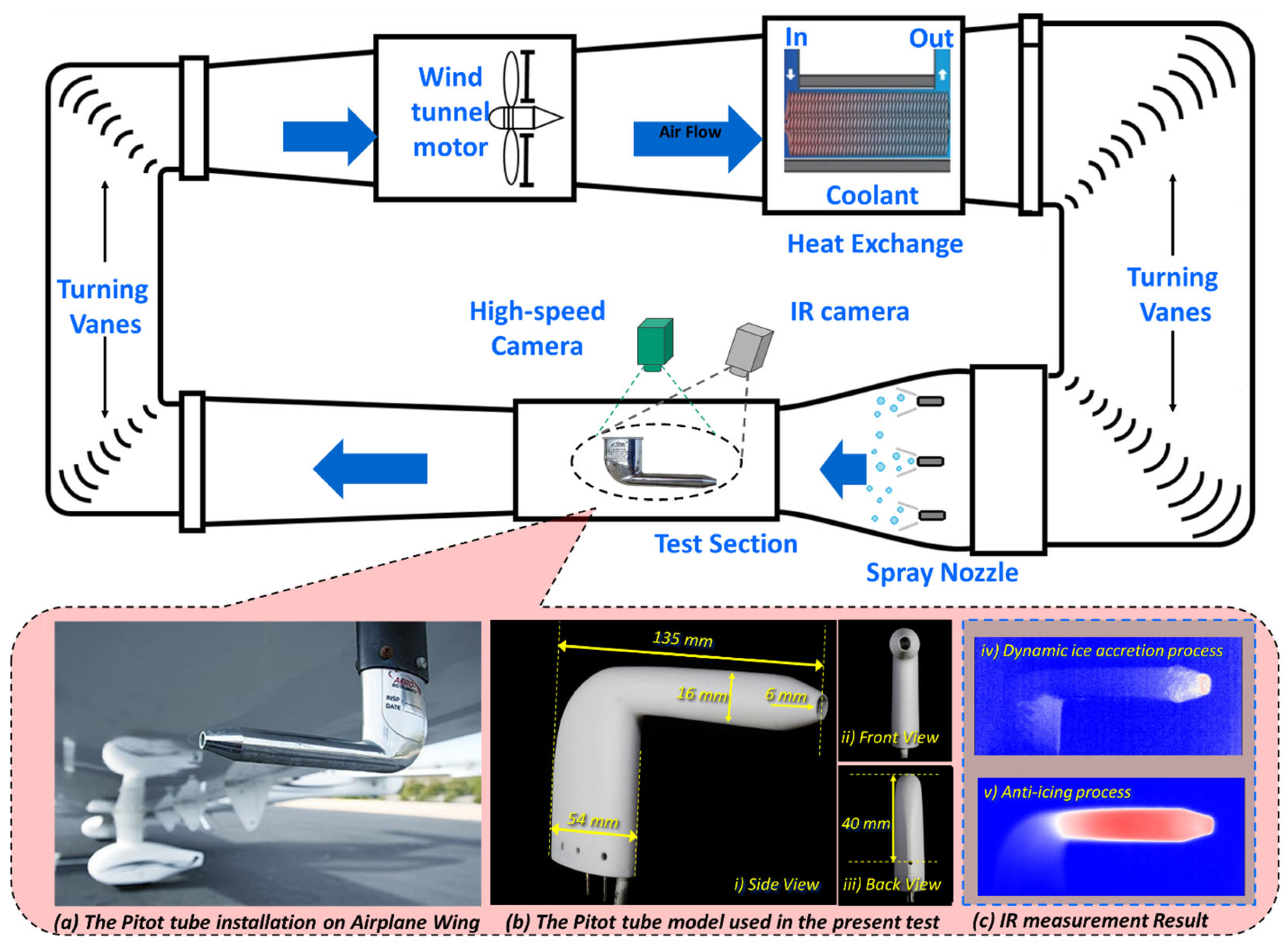
Figure 1. Schematic of the ISU-IRT used for the present study.
Aerospace 12 00862 g001
Figure 2. Acquired images of water droplets on the two compared surfaces.
Aerospace 12 00862 g002
Figure 3. Typical snapshots of dynamic ice accretion process on the Pitot probe (baseline case).
Aerospace 12 00862 g003
Figure 4. IR thermal imaging results to quantify the unsteady heat transfer process over the surface of the Pitot probe model under the glaze ice condition.
Aerospace 12 00862 g004
Figure 5. (a) Typical snapshots of dynamic ice accretion process on the Pitot probe with SHS coating, (b) extracted temperature plot at three selected points.
Aerospace 12 00862 g005
Figure 6. Acquired images to show the anti-icing accretion process over the pitot probe, (a) High-speed imaging snapshot and IR imaging snapshot when the electrothermal heater is being operated at p = 24 W, (b) High-speed imaging snapshot and IR imaging snapshot when the electrothermal heater is being operated at p = 48 W, (c) Comparison of measured temperature profiles at the three selected points.
Aerospace 12 00862 g006
Figure 7. Acquired images to show the de-icing accretion process over the pitot probe, (a) High-speed imaging snapshot and IR imaging snapshot when the electrothermal heater is being operated at p = 63 W, (b) High-speed imaging snapshot and IR imaging snapshot when the electrothermal heater is being operated at p = 132 W, (c) Comparison of measured temperature profiles at the three selected points.
Aerospace 12 00862 g007
Figure 8. Typical snapshots to reveal the dynamic anti-icing accretion processes over the pitot probe at a power output of 24 W, (a) Conventional thermal strategy, (b) Hybrid strategy, (c) Measured temperature profiles at the three selected points.
Aerospace 12 00862 g008
Figure 9. Typical snapshots to reveal the dynamic de-icing accretion processes over the pitot probe at a power output of 62 W, (a) Conventional thermal strategy, (b) Hybrid strategy.
Aerospace 12 00862 g009
Figure 10. Ice shedding time during the de-icing process with different strategies.
Aerospace 12 00862 g010
Table 1. Measured surface wettability and ice adhesion strength on the two compared surfaces.
Compared SurfaceStatic CA
(°)
Advance CA(°)Receding CA (°)CA Hysteresis (°)Ice Adhesion Strength at −10 °C (kPa)
Enamel Surface65 ± 585 ± 520 ± 5~601400 ± 100
SHS-coated surface157 ± 2159 ± 2154 ± 2~5110 ± 10
Table 2. Parametric Study Results for Anti-Icing Operation.
Power Consumption
(W)
Anti-Icing for the Total Pressure Tube
(Within 200 s)
Anti-Icing for the Probe Holder
(Within 200 s)
Heating StrategyHybrid Strategy Heating StrategyHybrid Strategy
9SuccessSuccessFailFail
14SuccessSuccessFailFail
24SuccessSuccessFailSuccess
35SuccessSuccessFailSuccess
40SuccessSuccessFailSuccess
48SuccessSuccessSuccessSuccess
Disclaimer/Publisher’s Note: The statements, opinions and data contained in all publications are solely those of the individual author(s) and contributor(s) and not of MDPI and/or the editor(s). MDPI and/or the editor(s) disclaim responsibility for any injury to people or property resulting from any ideas, methods, instructions or products referred to in the content.