Abstract
Tensegrity is a lightweight, self-stressing, and self-stabilizing structure made up of cables and bars, with each member bearing either tension or compression but not affected by shear stress. This design allows for optimal utilization of the material properties of the members. In a tensegrity basic unit, the bar members are of equal length, while the cable members come in three lengths: lower-end surface horizontal cable, upper-end surface horizontal cable, and stayed cable. The tensegrity basic unit with equal cable length simplifies this further by ensuring that all cables are the same length, resulting in a structure with only two member lengths, i.e., bar length and cable length, enhancing interchangeability. In order to find the form without the action of external forces, the force density coefficient ratio is introduced. By performing a force balance analysis on any node of the unit, the equilibrium equation of the structure is determined, incorporating the additional constraint of equal cable length. Two methods are employed to ascertain the force density coefficient ratio of each member in the unit: the theoretical derivation method based on the stable configuration condition of the tensegrity basic unit with equal cable length, and the method of solving the characteristic equations of the force density matrix. A program is developed to validate the form-finding method using basic units with three, four, five, and six bars as examples. The results show that the model accurately represents the physical structure, confirming the reliability of the form-finding methods.
1. Introduction
Tensegrity is a contraction of tensile and integrity. Tensegrity structures are self-supporting and self-stressing spatial structures that consist of a continuous tensile member wrapped around a discontinuous compressive member [1]. According to Fuller, gravity can be understood as an equilibrium web of tensions, with each planet being an isolated point in this web. This concept aligns with the principle of tensegrity, where the universe operates based on tension [2]. Tensegrity structures are designed in harmony with natural laws, leveraging the inherent properties of materials to achieve maximum efficiency. This structural form is particularly valued for its ability to fulfill the criteria of “lightness”.
The tensegrity basic unit with equal cable length is a variation of the traditional tensegrity structure where all cable members are set to have the same length. This means that the upper-end surface horizontal cables, lower-end surface horizontal cables, and stayed cables all have identical length, resulting in only two distinct lengths in the structure: cable length and bar length. This simplification in members streamlines production by reducing the types of required lengths, ultimately shortening the production cycle and cutting down on costs. Additionally, during installation, the identical cable members eliminate the need for numbering, allowing for flexible installation and ultimately saving time and improving efficiency. Furthermore, in terms of maintenance, the interchangeability of identical cable members helps reduce maintenance costs.
The tensegrity structure consists solely of compressed bars and cables, and the balanced pressure between them plays a crucial role in shaping and stiffening the structure [3]. Various parameters, such as the spatial position of nodes, member connections, tensile and compressive properties, initial length, and sectional stiffness, determine the state of the structure [4,5]. To ensure structural stability, the geometric shape and size of the tensegrity structure must adhere to specific requirements. The initial shape of a structure is crucial as it represents a stable self-equilibrium state. This shape is determined through a form-finding process, where shape parameters are analyzed as key factors under specific conditions. Form-finding ensures the structure’s stability and ability to withstand external forces. “Form-finding” aims to achieve two objectives simultaneously: defining the geometric shape and ensuring self-stress [6,7].
Motro classifies form-finding techniques into two main categories based on different control parameters: the “shape control approach” and the “internal force control approach”. The “shape control approach” focuses on creating a tensegrity structure that is constructible without considering component length, size, or post-formation structural properties, and stability is achieved through an empirical trial-and-error process, making it suitable for simple models. In contrast, the “internal force control approach” is preferred by most scholars [8,9,10,11] and involves the analytical method [12], nonlinear programming [13,14,15,16,17], dynamic relaxation [18,19,20,21,22,23,24,25], force density analysis [26,27,28,29,30,31,32,33,34,35,36,37,38,39,40,41], energy analysis [42,43,44,45,46], and the reduced stiffness technique [47,48,49,50]. These methods employ theoretical models to ensure that the structural system meets stress requirements by simultaneously determining geometric shape and prestressed status, resulting in highly accurate structures.
This study utilizes force density [26] to determine the shape of a tensegrity basic unit with equal cable length and provides a detailed analysis of its form-finding process. Section 2 outlines the fundamental assumptions of the force density method, the equilibrium equation of the tensegrity structure, and the additional conditions of tensegrity basic unit with equal cable length. Section 3 presents the node coordinates of tensegrity basic unit with equal cable length and conducts a theoretical analysis of the force density characteristics of the fundamental unit based on node coordinate balance. Section 4 presents the characteristic polynomial representation form of the force density matrix and discusses the conditions to be satisfied for stable configuration of basic unit. Section 5 validates the method through illustrative examples.
2. Balance Analysis of Tensegrity Basic Unit with Equal Cable Length
The basic unit of a tensegrity structure consists of cables and bars connected at nodes. All members are balanced when the tensegrity unit is in a balanced state [51,52,53]. The unique configuration of a tensegrity structure allows for the clear display and expression of interactions between components. Observers can easily see the action points (nodes) and action directions (member directions) of the structural forces, as shown in Figure 1.
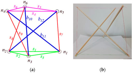
Figure 1.
The structure of a three-bars tensegrity unit: (a) the structure diagram; (b) the physical diagram.
The process of form-finding in tensegrity structural design involves determining the position information of each component once the stable configuration of the unit is achieved, essentially identifying the position information of each node. Tensegrity structures can be likened to space trusses, with all components considered as two-force bars. External forces act on the nodes, which are abstracted as spherical hinge links. The node method is preferable for deriving force balance equations for all components, with three independent equilibrium equations at each node [54]. Due to the uncertain geometric relationships between components, analytical solutions can be obtained using Cartesian vectors.
2.1. The Basic Assumptions of the Force Density Method
The force density form-finding method [26] was developed by Sheck in 1974 for cable-net structures. This method involves determining the force length ratio (force density) for each component in the structure. Linear static equilibrium equations are derived by performing a static analysis on each node in the structure and incorporating the concept of force density. The force density method allows for the calculation of the force density coefficient and node coordinates of each member in a stable configuration, essentially transforming the form-finding problem of the structure into a mathematical problem of solving equilibrium equations.
The fundamental assumptions for the force density approach in form-finding for tensegrity basic unit with equal cable length are as follows:
- The geometric topology of the structure is understood;
- The connections between each component are assumed to be frictionless hinges;
- The self-weight of the structure is not taken into account, and no external load is applied;
- Buckling of the bars is not considered; only axial tension and compression are transmitted between components;
- Dissipation and the effects of forces on the structure are not taken into account;
- The force density of each member always remains constant.
2.2. Representation of the Balance of Tensegrity Structures
When applying the force density method to determine form, it is assumed that the geometric topological form (connection matrix) of the structure is known. If the number of bar members of the unit is denoted as , which is defined as the main fractal parameter, then the total number of nodes can be calculated (). The lower-end surface node is represented by , ; the upper-end surface node is represented by , , and cable members. The total number of members in the structure can then be determined ().
In the structure, the node coordinates and node coordinate matrix are as follows:
The connection relationships between nodes and members of tensegrity structures as show in Figure 2. Nodes and serve as the initial and final points of component in a sequential manner. The topology of the structure is described using the unit-node connection matrix [26], which is a matrix.
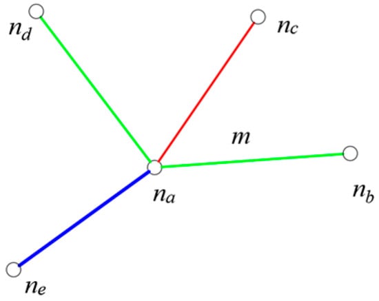
Figure 2.
The connection relationships between nodes and members of tensegrity structures.
With the aid of Figure 2, for each branch , we have the two matched node numbers and . The connection matrix is defined by
The nonlinear equilibrium equations of any node in the tensegrity structure are as follows:
where is the sum of expressions of all members whose end point is ; , , are, respectively, the coordinate components of the node in the direction of , , and ; is the length of the member ; is the internal force of member ; and , , and are the components of external force on node in the directions of , , and .
We define the ratio of the axial force of the member to the initial length of the member as the force density.
Then, the equilibrium Equation (4) can be expressed as follows:
Let the force density vector and the force density diagonal matrix be as follows:
By utilizing node coordinate matrix (2) and connection matrix (3), it is possible to calculate the projection of the component in the direction of three coordinate axes, that is, the coordinate difference between the two connected nodes.
Tensegrity structures are characterized by self-stress and self-balance, remaining stable in the absence of external loads. The equilibrium of a tensegrity structure can be represented in matrix form.
Let the common coefficient of the system of equilibrium equations be the force density matrix.
Then, the equilibrium equation can be expressed as follows:
The force density matrix is a generalized Gaussian transformation of matrix ; and the change of force density vector can represent the change of stable structural shape.
If the basic unit of the tensegrity is stable, then the equilibrium equation has a non-zero solution, and the following conditions must be met:
where is the dimension of the tensegrity structure; when the structure is in plane configuration, ; and when it is in space configuration, .
2.3. Determining Additional Conditions for Stable Configuration of a Tensegrity Basic Unit with Equal Cable Length
For the tensegrity basic unit with equal cable length, the lengths of all the cables in the structure are the same as .
The additional conditions for the stable configuration can be expressed as follows:
Let the member matrix be :
The additional condition is that in the first rows of elements of the matrix, all norms of each row of elements are fixed values .
3. The Force Density Characteristic Analysis of Tensegrity Basic Unit with Equal Cable Length
3.1. The Ode Coordinates of Tensegrity Basic Unit with Equal Cable Length
In the basic unit of the equal cable length tensegrity, all cables have the same length, resulting in the upper and lower-end surface cables forming two regular polygons with the same shape. The center of the circumscribed circle of the lower-end surface cable is designated as the zero point () of the coordinate system. The plane where the circumscribed circle lies is the reference plane, and the line from this plane pointing to the center of the circumscribed circle of the upper-end surface cable represents the positive axis direction. Each node in the end face equally divides its circumscribed circle, from which the coordinates of each node in the stable configuration can be obtained.
where is the stayed cable connection method, defined as the auxiliary fractal parameter, , , .
3.2. The Force Density Attribute of Tensegrity Basic Unit with Equal Cable Length
Each node in the tensegrity structure is linked to a total of four members from three different categories. Similar components share the same properties. We assume that the force densities of horizontal cables (including lower-end surface horizontal cables and upper-end surface horizontal cables), stayed cables, and bars are in order for , , and .
When the tensegrity is in a stable configuration, the connection relationship between any node and other members is illustrated in Figure 3. By utilizing Equation (6), the force balance of any node can be determined. Focusing on the end node as the subject of study, we can derive the following equation:
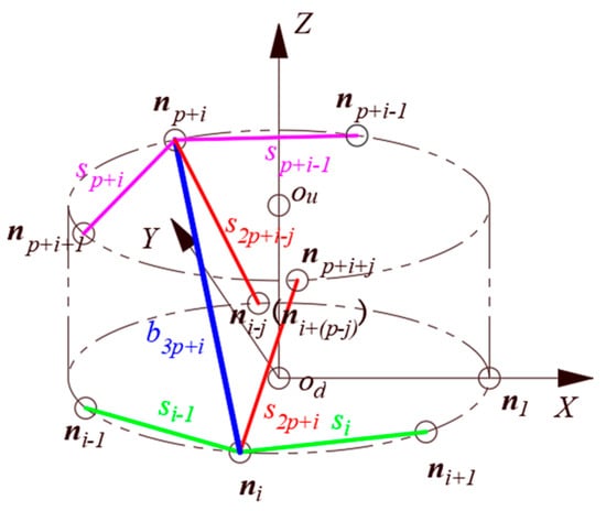
Figure 3.
The connection relationship between any node and other components.
The node is experiencing tensile forces from horizontal cables and (these two forces are located on the coordinate plane), the tensile force of stayed cable , and pressure from the bar . The total force acting on the node is zero in all three coordinate axis directions.
In the direction of the coordinate axis, the node is only affected by stayed cable and bar . The other nodes connected by the stayed cable and the bar are, respectively, and . These two nodes are positioned on the circumscribed circle of the upper-end surface. The coordinates are both the height of the structure; that is, and can be substituted into Equations (6) and (19) to obtain the necessary values.
Namely, the force densities size of the stayed cable and the bar are the same. In order to facilitate the distinction between the tension and compression properties of the members, it is assumed that , .
Substituting Equations (17)–(19) into Equation (6) to obtain the force balance equation of the node in the coordinate direction, simplification can be used to obtain the functional relationship between horizontal cables and stayed cables.
There is always in the formula, so we set , .
In the basic unit body of the tensegrity structure, the ratio of force density coefficients for the end surface horizontal cables, stayed cables, and bar members can be expressed as
When stabilizing the basic unit of the tensegrity structure with equal cable lengths, it is important to ensure that the main and auxiliary fractal parameters meet specific conditions. Specifically, each main fractal parameter should be able to build, at most, five stable structures with equal cable length [55].
So, the force density coefficient ratio between the horizontal cable and the stayed cable can be obtained as follows:
where, .
Taking three-bar, four-bar, five-bar, and six-bar structures as examples, the force density coefficient ratios at different are listed in Table 1.

Table 1.
The force-density coefficient ratios at different .
It can be seen from the table that the stable configuration of the system exhibits different force density ratios depending on the number of bars. When there are three bars, there is only one force density ratio. With four bars, there are two force density ratios, and when , the force density ratio equals one. For five bars, there are two force density ratios. In the case of six bars, there are three force density ratios; when , the force density ratio equals two; when , the force density ratio is one.
The force density ratio varies with the number of bars of different values of , as illustrated in Figure 4 and supported by the data in Table 1, along with Equation (24).
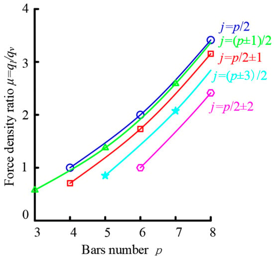
Figure 4.
The relationship curve between bar number and cable force density ratio.
Figure 4 illustrates the function relationship curve for various values. The analysis reveals that there are only five distinct functional relationships between the force density ratios of horizontal cables and stayed cables at the end surfaces of tensegrity basic units with equal cable length. As the main and auxiliary fractal parameters increase, the force density ratios of horizontal and stayed cables also increase infinitely. Notably, when the main fractal parameter remains constant, the force density ratio is greater when the auxiliary fractal parameter is closer to in value.
3.3. The Force Density Matrix Attribute of Tensegrity Basic Unit with Equal Cable Length
The main fractal parameter is the number of bars in the structure, and the auxiliary fractal parameter is the connection method of the stayed cables. The force density matrix is a symmetrical square matrix of . The main diagonal element represents the sum of force densities of all components connected to the node, . In matrix , the element in row and column is the same as the element in row and column , and it is the opposite of the force density of the member connecting nodes and . Using to represent the force density matrix with bars structures. Taking three-bar nine-cable, four-bar twelve-cable, five-bar fifteen-cable, and six-bar eighteen-cable structures as examples, when the auxiliary parting parameter is given, the force density matrix can be expressed as follows:
where , .
The matrix and are all matrix of . The matrix is a symmetric matrix; the main diagonal elements are ; the upper right corner, lower left corner, and sub-diagonal elements are ; and the remaining elements are all zero. The matrix is a similar band matrix with half bandwidth of three; the main diagonal elements are ; the elements on the third diagonal and above the main diagonal are ; and the remaining elements are all zero.
There are five non-zero elements and zero elements in each row or column in .
4. The Form-Finding of Tensegrity Basic Units with Equal Cable Length
4.1. Characteristic Polynomials of the Force Density Matrix of Tensegrity Structures
In the matrix , represents an eigenvalue of the force density matrix . The characteristic polynomial of is obtained by calculating the determinant of the matrix, resulting in the following equation:
where, , , is the trace of the matrix , and ;
The remaining coefficients can be expressed by symmetric polynomials [56,57,58].
where is the determinant of a new square matrix formed by the trace of the product of the force density matrices .
where .
Expanding the determinants by rows, the can be simplified to the following form:
where .
4.2. Stability Conditions of Tensegrity Structures
When a tensegrity structure has a stable configuration, the following conditions need to be met: ; (planar structure); (spatial structure).
4.2.1. Stable Configuration Conditions for Planar Structures
If the tensegrity structure is a planar structure, the rank of the force density matrix is . It can be seen that , , and . Substituting into Equation (29), we obtain , , and . It can be seen from Equation (31) that
After the above analysis, the stability condition of the planar structure can be obtained as follows:
4.2.2. Stable Configuration Conditions for Spatial Structures
It follows from the same principle that if the tensegrity structure is a spatial structure, the rank of the force density matrix is , , , , and . It can be seen from Equation (31) that
After sorting out the above, the stability condition of the spatial structure can be obtained as follows:
To sum up, the stability condition of the tensegrity structure with equal cable length can be expressed as follows:
4.3. Stability Conditions of Tensegrity Structures with Equal Cable Length
The end surface nodes on the basic unit of a tensegrity structure are evenly distributed along the circumscribed circle of the end surface. This means that the end surface nodes divide the circumscribed circle equally. We establish the space rectangular coordinates according to Section 3.1; the lower-end surface nodes are positioned in a plane with coordinates all set to zero, while the upper-end surface nodes are located on the circumscribed circle at a height equal to the height of the unit. In a tensegrity structure with equal cable length, all cables are of the same length, requiring node coordinates to satisfy a specific Equation (16). The stability conditions for tensegrity basic unit with equal cable length are outlined as follows:
- ;
- The end surface node coordinates equally divide the respective end surface circumscribed circles (X direction and Y direction);
- ;
- , .
- The form-finding process involves the following:
- Determining the connection matrix and force density matrix of the structure;
- Solving the force density coefficient using Equation (37) and numbering them sequentially;
- Substituting a force density coefficient into Equation (12) to solve the node coordinate matrix and checking if Equation (16) is satisfied. If not, the process repeats by changing the force density coefficient value. If all values are tried and Equation (16) is still not satisfied, the program concludes with a “no solution” output;
- If Equation (16) is satisfied, the force density coefficient and node coordinates are output, and the program ends.
The programming flow chart for determining the stable configuration of the tensegrity basic unit with equal cable length is illustrated in the Figure 5 below.
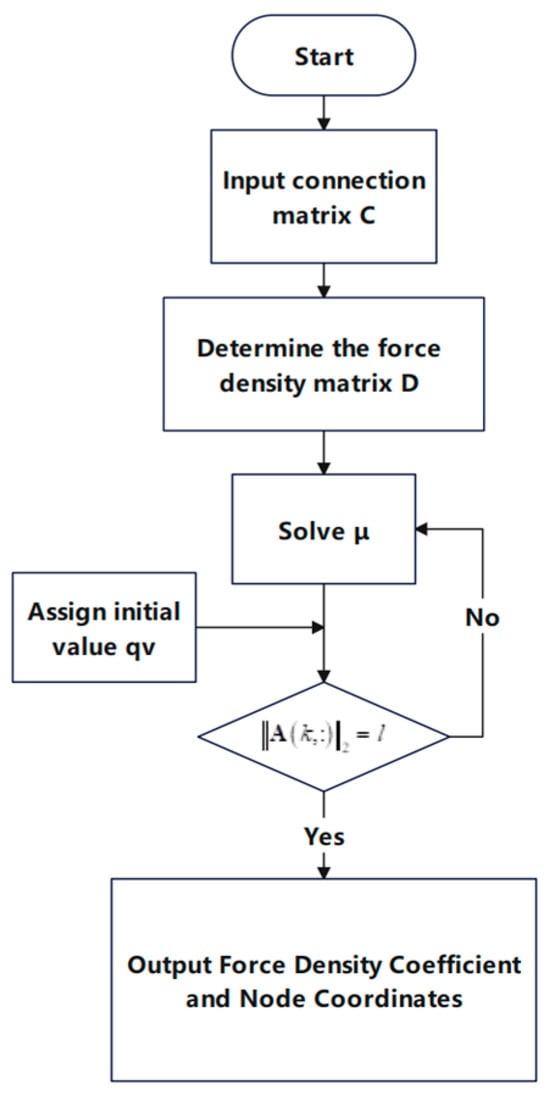
Figure 5.
Form-finding programming flow chart of tensegrity basic unit with equal cable length.
5. Examples
5.1. Form-Finding of Planar Structure
Taking , , , and as examples, the planar configuration is satisfied with , , and . The condition must be met for the tensegrity overall configuration of equal cable lengths in a stable plane.
According to the method outlined in this study, the programming and form-finding processes were conducted. The equation has no solution when , , and . Specifically, tensegrity structures with three, four, and five bars with equal cable length do not possess a stable configuration in a plane.
For the six-bar configuration with an auxiliary fractal parameter of one, the force density matrix is determined based on the overall force density attribute of equal cable length tensegrity in Section 3.3. The value of is determined following the method outlined in the article, and it consistently results in , indicating that when in the six-bar configuration, only one planar structure with equal cable length can be formed. This aligns with the data in Table 1 and supports the conclusion in the literature [55] that when and , . Figure 6 illustrates the configuration based on the conclusion data from the literature [55], showing the physical layout when the main and auxiliary fractal parameters are and , respectively. The model proposed in this paper is in line with this physical configuration.
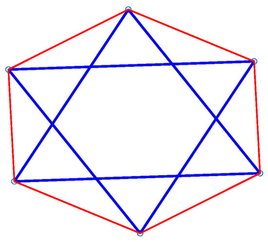
Figure 6.
The planar structure model of six bars tensegrity with equal cable length.
5.2. Form-Finding of Spatial Structure
Taking the three-bar nine-cable , four-bar twelve-cable , five-bar fifteen-cable , and six-bar eighteen-cable tensegrity structures with equal cable length in space as examples, the form-finding of the spatial structure is carried out.
The force density matrix of three-bar tensegrity structures with equal cable length is as shown in Equation (25), where , , and . When the configuration is stable, , , , and .
The calculation results show that , which means that . These results align with the findings presented in Table 1 (). The model is illustrated in Figure 7.

Figure 7.
Spatial structure model of tensegrity with equal cable length: (a) three-bar model; (b) four-bar model; (c) five-bar model; (d) six-bar model.
The force density matrix of four-bar tensegrity structures with equal cable length is as shown in Equation (26), where, , , and . When the configuration is stable, , , , and . The calculation results show that ,which means that . These results align with the findings presented in Table 1. The model is illustrated in Figure 7.
The force density matrix of five-bar tensegrity structures with equal cable length is as shown in Equation (27), where, , , and. When the configuration is stable, , , , and . The calculation results show that , which means that . These results align with the findings presented in Table 1. The model is illustrated in Figure 7.
The force density matrix of six-bar tensegrity structures with equal cable length is as shown in Equation (27), where, , , and. When the configuration is stable, , , , and . The calculation results show that , which means that . These results align with the findings presented in Table 1. The model is illustrated in Figure 7.
The models derived from the data analyzed and computed using the methodology outlined in this study are in alignment with the physical configurations described in the literature [53], thereby confirming the conclusion.
6. Conclusions
The tensegrity structure is extensively utilized across various fields due to its exceptional configuration characteristics. The tensegrity basic unit with equal cable lengths undergoes further improvement to enhance interchangeability. To achieve the morphological characteristics of the structure without external forces, the force density coefficient ratio is introduced. This article utilizes node coordinates and member force density as variables to outline the force balance equation of the stable configuration. The force density coefficient ratio is then determined through two methods to complete the form-finding process successfully. The two methods verify each other. The findings are compared with those documented in the existing literature, demonstrating the efficacy of the method in identifying self-equilibrating configurations. The specific methods are as follows:
- This paper introduces the primary and auxiliary fractal parameters by applying node force balance theory and examining the stable configuration conditions of the tensegrity basic unit with equal cable lengths. Consequently, the force density coefficient ratios for the end surface horizontal cables, stayed cables, and bars can be derived.
- The expression for the force density matrix is derived by applying the force balance equation to the stable configuration. The ratio of the force density coefficients is determined by analyzing the rank deficiency of the force density matrix. This rank deficiency can be interpreted as a condition whereby the partition coefficient of the force density polynomial is equal to zero. The coefficients of the force density polynomial can be calculated by evaluating the determinant of a matrix formed by the trace of the powers of the force density. Ultimately, the theoretical ratio of the density coefficients is established by setting the determinant to zero.
Author Contributions
Conceptualization, Y.Z. and A.L.; methodology, Y.Z.; software, Y.Z.; validation, Y.Z., A.L. and H.L.; formal analysis, Y.Z.; investigation, Y.Z.; resources, Y.Z.; data curation, Y.Z.; writing—original draft preparation, Y.Z.; writing—review and editing, Y.Z.; visualization, Y.Z.; supervision, Y.Z. All authors have read and agreed to the published version of the manuscript.
Funding
This research received no external funding.
Data Availability Statement
Data is unavailable due to privacy.
Conflicts of Interest
The authors declare no conflicts of interest.
References
- Motro, R. Tensegrity: Structural Systems for the Future; Elsevier: Amsterdam, The Netherlands, 2003. [Google Scholar]
- Richard, B.F. Tensile-Integrity Structures. U.S. Patent Application No. US3063521A, 13 November 1962. [Google Scholar]
- Zhang, J.; Ohsaki, M. Tensegrity Structures; Springer: Berlin/Heidelberg, Germany, 2015; Volume 7. [Google Scholar]
- Deng, H. Analysis of Cable-Bar Assemblies: Theories and Methods; Science Press: Beijing, China, 2018. [Google Scholar]
- Chen, W. Theoretical Method and Engineering Application of Cable-Strut Tension Structure Design and Analysis; Science Press: Beijing, China, 2021. [Google Scholar]
- Luo, Y. Morphology of Spatial Structure; Science Press: Beijing, China, 2022. [Google Scholar]
- Xu, X. Morphological Design and Control of Tensegrity Structure; Science Press: Beijing, China, 2017. [Google Scholar]
- Xue, Y.; Luo, Y.; Xu, X. Form-finding of cable-strut structures with given cable forces and strut lengths. Mech. Res. Commun. 2020, 106, 103530. [Google Scholar] [CrossRef]
- Wang, Y.; Xu, X.; Luo, Y. A unifying framework for form-finding and topology-finding of tensegrity structures. Comput. Struct. 2021, 247, 106486. [Google Scholar] [CrossRef]
- Wang, Y.; Xu, X.; Luo, Y. Topology Design of General Tensegrity with Rigid Bodies. Int. J. Solids Struct. 2020, 202, 278–298. [Google Scholar] [CrossRef]
- Xu, X.; Huang, S.; Wang, Y.; Luo, Y. A generalized objective function based on weight coefficient for topology-finding of tensegrity structures. Appl. Math. Model. 2023, 115, 541–567. [Google Scholar] [CrossRef]
- Koohestani, K. On the analytical form-finding of tensegrities. Compos. Struct. 2017, 166, 114–119. [Google Scholar] [CrossRef]
- Xu, X.; Wang, Y.; Luo, Y. Finding member connectivities and nodal positions of tensegrity structures based on force density method and mixed integer nonlinear programming. Eng. Struct. 2018, 166, 240–250. [Google Scholar] [CrossRef]
- Miki, M.; Kawaguchi, K. Extended force density method for form-finding of tension structures. J. Int. Assoc Shell Sp. 2010, 51, 291–303. [Google Scholar]
- Ohsaki, M.; Zhang, J. Nonlinear programming approach to form-finding and folding analysis of tensegrity structures using fictitious material properties. Int. J. Solids Struct. 2015, 69–70, 1–10. [Google Scholar] [CrossRef]
- Miki, M.; Kawaguchi, K. Three-term method and dual estimate: Form finding problems of tension structures and large deformation problems of continuum bodies. J. Stage 2012, 77, 611–618. [Google Scholar]
- Masic, M.; Skelton, R.E.; Gill, P.E. Algebraic tensegrity form-finding. Int. J. Solids Struct. 2005, 42, 4833–4858. [Google Scholar] [CrossRef]
- Zhang, H.; Shan, J. Initial form finding and free vibration properties study of membrane. In Proceedings of the Xi’an International Conference of Architecture and Technology, Proceedings-Architecture in Harmony, Xi’an, China, 23–25 September 2006; p. 316. [Google Scholar]
- Xu, X.; Yu, Y.; Luo, Y.; Shen, Y. Tensegrity Form-Finding Using Finite Particle Method. Adv. Mater. Res. 2011, 201, 1166. [Google Scholar] [CrossRef]
- Collins, M.; Cosgrove, T. Dynamic relaxation modelling of braced bending active gridshells with rectangular sections. Eng. Struct. 2019, 187, 16–24. [Google Scholar] [CrossRef]
- Ye, J.; Feng, R.; Zhou, S. The Modified Dynamic Relaxation Method for the Form-Finding of Membrane Structures. Adv. Sci. Lett. 2011, 4, 2845–2853. [Google Scholar] [CrossRef]
- Kabasi, S.; Marbaniang, A.L.; Ghosh, S. Form-finding of frame-supported non-minimal tensile membrane structures for anisotropic prestress using physics-informed neural networks. Struct. Multidiscip. Optim. 2024, 67, 56. [Google Scholar] [CrossRef]
- Miki, M. Structural and Geometric Applications of the Geodesic Dynamic Relaxation Method. In Proceedings of the Textiles Composites and Inflatable Structures VII: Proceedings of the VII International Conference on Textile Composites and Inflatable Structures, Barcelona, Spain, 19–21 October 2015; pp. 26–33. [Google Scholar]
- Wang, X.; Cai, J.; Yang, R.; Feng, J. Form-finding of deployable mesh reflectors using dynamic relaxation method. ACTA Astronaut. 2018, 151, 380–388. [Google Scholar] [CrossRef]
- Ali, N.B.H.; Rhode-Barbarigos, L.; Smith, I.F. Analysis of clustered tensegrity structures using a modified dynamic relaxation algorithm. Int. J. Solids Struct. 2011, 48, 637–647. [Google Scholar]
- Schek, H.O.R. The force density method for form finding and computation of general networks. Comput. Methods Appl. Mech. Eng. 1974, 3, 115–134. [Google Scholar] [CrossRef]
- Zhang, J.Y.; Ohsaki, M. Adaptive force density method for form-finding problem of tensegrity structures. Int. J. Solids Struct. 2006, 43, 5658–5673. [Google Scholar] [CrossRef]
- Heng, T.; Zhao, L.; Liu, K.; Yi, J.; Duan, X.; Sun, Z. An Improved Form-Finding Method for Calculating Force Density with Group Theory. In Proceedings of the 2021 11th International Conference on Intelligent Control and Information Processing (ICICIP), Dali, China, 3–7 December 2021; pp. 119–124. [Google Scholar]
- Zhang, L.; Zhu, S.; Li, S.; Xu, G. Analytical form-finding of tensegrities using determinant of force-density matrix. Compos. Struct. 2018, 189, 87–98. [Google Scholar] [CrossRef]
- Cai, J.; Wang, X.; Deng, X.; Feng, J. Form-finding method for multi-mode tensegrity structures using extended force density method by grouping elements. Compos. Struct. 2018, 187, 1–9. [Google Scholar] [CrossRef]
- Wang, Y.; Xu, X.; Luo, Y. Form-finding of tensegrity structures via rank minimization of force density matrix. Eng. Struct. 2021, 227, 111419. [Google Scholar] [CrossRef]
- Shang, R.; Zhao, Y.; Yin, Z. Geometric Drawing Method for Form-finding and Force-finding to Triangular Prism Tensegrity with End Surfaces not Paralleled. J. Phys. Conf. Ser. 2020, 1624, 052012. [Google Scholar] [CrossRef]
- Chen, Y.; Sun, Q.; Feng, J. Improved Form-Finding of Tensegrity Structures Using Blocks of Symmetry-Adapted Force Density Matrix. J. Struct. Eng. 2018, 144, 04018174. [Google Scholar] [CrossRef]
- Koohestani, K.; Guest, S. A new approach to the analytical and numerical form-finding of tensegrity structures. Int. J. Solids Struct. 2013, 50, 2995–3007. [Google Scholar] [CrossRef]
- Koohestani, K. Form-finding of tensegrity structures via genetic algorithm. Int. J. Solids Struct. 2012, 49, 739–747. [Google Scholar] [CrossRef]
- Tran, H.C.; Lee, J. Advanced form-finding of tensegrity structures. Comput. Struct. 2010, 88, 237–246. [Google Scholar] [CrossRef]
- Lee, S.; Lee, J. Form-finding of tensegrity structures with arbitrary strut and cable members. Int. J. Mech. Sci. 2014, 85, 55–62. [Google Scholar] [CrossRef]
- Zhao, L.; Heng, T.; Liu, K.; Sun, Z. A zeroing neural network model for form-finding problems: A nonlinear optimization approach. Eng. Appl. Artif. Intell. 2024, 128, 107492. [Google Scholar] [CrossRef]
- Hernández, L.; Fernández-Ruiz, M.A.; Gil-Martín, L.M. Influence of the level of connectivity on the members of the Octahedron and X-Octahedron families of tensegrities. Eng. Struct. 2023, 296, 116927. [Google Scholar] [CrossRef]
- Jiang, J.; Yin, X.; Xu, G.; Wang, Z.; Zhang, L. A unified analytical form-finding of truncated regular octahedral tensegrities. Int. J. Mech. Sci. 2023, 239, 107857. [Google Scholar] [CrossRef]
- Cao, Z.; Luo, A.; Feng, Y.; Liu, H. Self-Equilibrium Analysis and Minimal Mass Design of Tensegrity Prism Units. J. Appl. Mech. 2024, 91, 071007. [Google Scholar] [CrossRef]
- Liu, H.; Sanaullah; Vumiliya, A.; Luo, A. A resource-efficient form-finding approach to tensegrity structures. Eng. Comput. 2024, 41, 1–17. [Google Scholar] [CrossRef]
- Wang, H.; Huang, Z.; Yi, J.; Jiang, W.; He, Z. Static Analysis on Some Typical Tensegrities with Additional Cables. J. Eng. Mech. 2022, 148, 04021162. [Google Scholar] [CrossRef]
- Zhang, L.; Li, Y.; Cao, Y.; Feng, X. Stiffness matrix based form-finding method of tensegrity structures. Eng. Struct. 2014, 58, 36–48. [Google Scholar] [CrossRef]
- Juan, S.H.; Tur, J.M.M. Tensegrity frameworks: Static analysis review. Mech. Mach. Theory 2008, 43, 859–881. [Google Scholar] [CrossRef]
- Rhode-Barbarigos, L.; Ali, N.B.H.; Motro, R.; Smith, I.F. Designing tensegrity modules for pedestrian bridges. Eng. Struct. 2010, 32, 1158–1167. [Google Scholar] [CrossRef]
- Vassart, N.; Motro, R. Multiparametered form finding method: Application to tensegrity systems. Int. J. Space Struct. 1999, 14, 147–154. [Google Scholar] [CrossRef]
- Kuhl, D.; Lim, Y.C.; Long, D.S. Tensegrity Structures—Computational and Experimental Tensegrity Mechanics. AIP Conf. Proc. 2017, 1863, 410005. [Google Scholar]
- Kleppner, D.; Kolenkow, R. An Introduction to Mechanics, 2nd ed.; Cambridge University Press: La Vergne, TN, USA, 2012. [Google Scholar]
- Hibbeler, R.C. Engineering Mechanics: Statics, Twelfth Edition—Instructor's Solutions Manual; Pearson Education: London, UK, 2010. [Google Scholar]
- Song, K.; Scarpa, F.; Schenk, M. Form-finding of tessellated tensegrity structures. Eng. Struct. 2022, 252, 113627. [Google Scholar] [CrossRef]
- Cao, Z.; Luo, A.; Liu, H.; Feng, Y. A novel torque application method for tensegrity structures. Mech. Based Des. Struct. Mach. 2024. [Google Scholar] [CrossRef]
- Liu, H.; Luo, A. Structure and Splicing of Tensegrity Unit; Harbin Engineering University Press: Harbin, China, 2019. [Google Scholar]
- Pytel, A.; Kiusalaas, J. Engineering Mechanics: Statics, 3rd ed.; Cengage Learning: Stamford, CT, USA, 2010; Volume 1. [Google Scholar]
- Zhao, Y.; Luo, A. Attribute analysis of tensegrity basic unit for equal cable length. In Proceedings of the 31st National Conference on Structural Engineering (No. 1), Press of Engineering Mechanics, Nanning, China, 5–8 October 2022; pp. 211–214. [Google Scholar] [CrossRef]
- Van Kortryk, T.S. Matrix exponentials, SU(N) group elements, and real polynomial roots. J. Math. Phys. 2016, 57, 021701. [Google Scholar] [CrossRef]
- Curtright, T.L.; Zachos, C.K. Elementary Results for the Fundamental Representation of SU(3). Rep. Math. Phys. 2015, 76, 401–404. [Google Scholar] [CrossRef]
- Curtright, T.L.; Fairlie, D.B.; Alshal, H. A Galileon Primer. arXiv 2020, arXiv:1212.6972. [Google Scholar]
Disclaimer/Publisher’s Note: The statements, opinions and data contained in all publications are solely those of the individual author(s) and contributor(s) and not of MDPI and/or the editor(s). MDPI and/or the editor(s) disclaim responsibility for any injury to people or property resulting from any ideas, methods, instructions or products referred to in the content. |
© 2024 by the authors. Licensee MDPI, Basel, Switzerland. This article is an open access article distributed under the terms and conditions of the Creative Commons Attribution (CC BY) license (https://creativecommons.org/licenses/by/4.0/).