1. Introduction
Jets are representative flow patterns present in nature and used in industry. By controlling the jets, achieving high functionality and efficiency and reducing the environmental impact resulting from industrial equipment is possible [
1]. Various jet characteristics are governed by the spatiotemporal development of large-scale vortex structures generated from shear layers. The behavior of vortex structures, including vortex emission and merging, considerably changes depending on the flow state at the nozzle exit [
2]. Jet control includes “passive control” achieved by changing nozzle shapes, installing tabs, ribs, and cylinders and “active control” using actuators [
3]. Passive control does not require energy input and is less likely to exert considerable control effects. Active control is used when seeking performance that cannot be achieved with passive control, because it consumes energy. The characteristics of passive and active control are described below.
In some studies, the nozzle shape was changed from a circular nozzle to an elliptical, triangular, or square nozzle. In elliptical jets, the major and minor axes of the elliptical vortex ring develop and diffuse interchangeably [
4,
5]. In triangular jets, the downstream flow is deformed by longitudinal vortices generated at the corners [
4]. In square jets, Kelvin–Helmholtz roll-up vortices are generated, and mixing is enhanced by the addition of tabs [
6]. Additionally, the addition of tabs to a circular nozzle can enhance and suppress jet diffusion and mixing of the jet [
7]. In addition, many studies have been conducted to promote jet diffusion by installing bluff bodies downstream of the nozzle exits to encourage vortex generation. In this regard, research on cylindrical bluff bodies is particularly active [
8,
9]. In combustion research, the improvement of the stability of lifted flames using the recirculation flows generated by disk-type bluff bodies has been investigated [
10];
The jet can be controlled and its shape can be deformed by installing and operating delta tabs, which are mechanical actuators at the jet outlet [
11]. However, as the jet velocity increases, the frequency of vortex generation that governs the jet flow increases, requiring jet control at high frequencies (several kilohertz). Mechanical actuators are difficult to drive at several kilohertz, making them unsuitable for fast jet flows. Another method uses the pressure wave output from speakers to control jets [
12]. However, concerns such as equipment enlargement and equipment complications limit the use of active control in practical environments.
Consequently, most control technologies used in devices utilizing jet phenomena are passive. However, passive control cannot always achieve the most effective control effects for changing the jet flow rate, because the nozzle structure or jet device shape cannot be changed during operation.
Meanwhile, studies combining disk-type bluff bodies and active control have been conducted using microflaps fabricated with microelectromechanical systems to control lifted flames. By driving the microflaps attached to the jet nozzle exit, researchers were able to control the coaxial double jets and improve the exhaust gas characteristics through active control of the lifted flames generated by bluff bodies [
13]. However, the issue with this research is that only studies on controlling low-velocity jets have been conducted, because of the slow driving frequency of the microflaps. Notably, this study controlled the jets by installing a high-frequency drivable dielectric barrier discharge (DBD) plasma actuator (DBD-PA) inside a circular nozzle. Our previous research revealed that controlling a circular jet with a DBD-PA inside the nozzle can control the frequency of vortex rings generated in the initial jet [
14]. The benefits of using DBD-PA to control jets include a faster response compared with those of mechanical fluid control methods, because of the use of electromagnetic phenomena, the ability to induce velocity fluctuations at any frequency using AC power, and its simple structure that makes it smaller, lighter, and easier to maintain than mechanical systems.
A burner nozzle for combustion is a typical industrial device in which a bluff body is installed above a circular nozzle. In burner systems in which fuel gas is expelled from the nozzle, a combustion flame forms and can be categorized into one of two types: an attached flame, in which the flame clings to the nozzle edges, and a lifted flame, in which the flame detaches from the nozzle.
When the jet velocity of the fuel gas is low, the velocity gradient of the boundary layer between the gas and the surrounding ambient air at the nozzle outlet balances with the combustion velocity, leading to the formation of an attached flame that adheres to the nozzle edges. Conversely, as the jet velocity increases, the gas velocity at the nozzle outlet exceeds the combustion velocity, causing the flame to detach from the nozzle edges, forming what is known as a lifted flame.
The lifted flame is established in a position at which the fuel–gas flow and combustion velocity are balanced. The lifted flame oscillates laterally and vertically, burning unstably due to fluctuations in the jet width resulting from the decline in the gas velocity downstream of the nozzle and the diffusion of the gas into the surrounding air. If the jet velocity of the fuel gas is further increased, the flame becomes unsustainable and may extinguish, leading to ignition failure.
The main characteristics of the lifted flame are as follows:
The oscillation of the lifted flame induces pressure fluctuations in the combustor, resulting in combustion noise;
The flame shape and position fluctuate due to the oscillatory nature of combustion, which may cause misfiring or allow unburned gases to escape without passing through the combustion zone;
Premature combustion before proper mixing of fuel gas and oxygen may lead to incomplete combustion and reduced combustion efficiency. The flame width of the lifted flame is typically larger than that of the attached flame, leading to a shorter flame length and a smaller combustor size (i.e., lower combustion load factor);
The lifted flame is inherently unstable because of its oscillatory burning pattern and is prone to extinction. Therefore, flame stabilizers are employed to enhance the stability of lifted flames. These stabilizers come in various shapes and sizes; one of them is a disk-type flame stabilizer installed above the nozzle. In a disk-type flame stabilizer, the recirculation flow is generated by the low-pressure region formed behind the bluff body on the disk’s reverse side. This recirculation flow facilitates the exchange of hot combustion gases with the recirculating gases, maintaining a high temperature in the recirculation area. Additionally, the flame stabilizer decreases the jet velocity and widens the jet width, which helps balance the fuel gas and combustion velocities.
The ultimate goal of this study is to mitigate the disadvantages associated with lifted flames (as outlined in points 1–4), which cannot be fully addressed by flame stabilizers alone, while enhancing the advantages and extending the flammable range through vibration suppression. To achieve this, the ejected gas is passively controlled by the flame stabilizer (bluff body) and actively controlled by the DBD-PA installed within the nozzle.
In this study, as an initial step toward controlling lifted flames, we present the results of jet flow control using the bluff body and the DBD-PA in the nozzle in the absence of combustion. Then, we determine whether the control of the jet flow by the combination of the flame stabilizer (bluff body) and the DBD-PA in the nozzle is effective for controlling lifted flames. For safety reasons, air was used as the working gas in the jet experiments because prolonged unburned fuel gas jetting poses considerable risks.
3. Experimental Setup
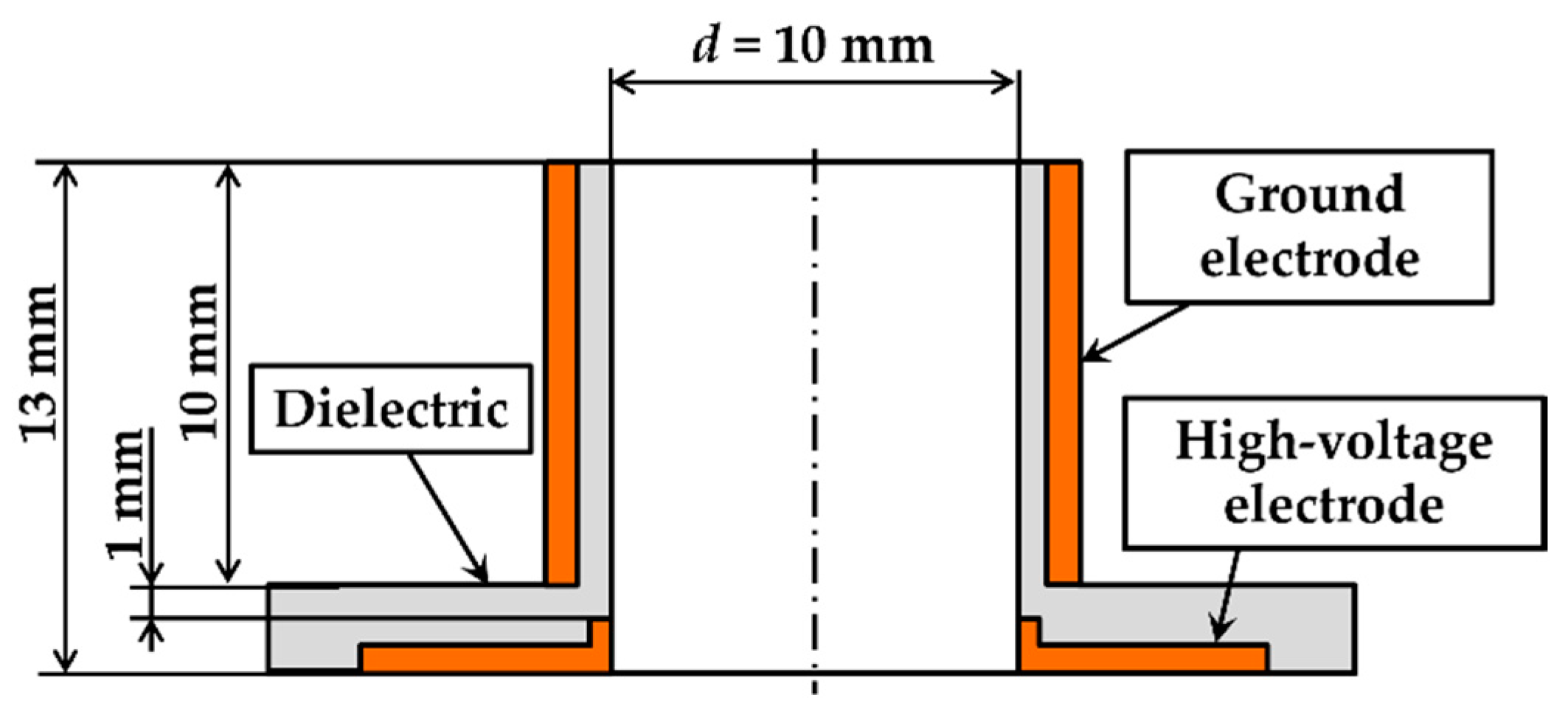
Figure 2 shows a cross-sectional view of the nozzle equipped with the internal DBD-PA used in this study. High-voltage-applied electrodes were placed inside a circular nozzle made of dielectric material, and ground electrodes were placed outside to form the DBD-PA. The nozzle exit had an inner diameter of
d = 10 mm (radius
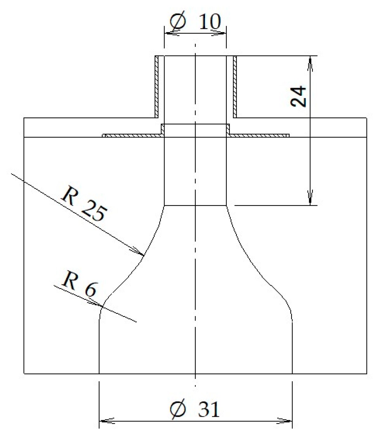
r = 5 mm). Considering the resistance to insulation voltage, machinable ceramics were chosen as the dielectric material. The electrodes were made of phosphor bronze processed into a cylindrical shape with a thickness of 0.5 mm and were fitted into the nozzle. The nozzle was placed at the tip of a converging nozzle with a contraction ratio of 9.6 (
Figure 3).
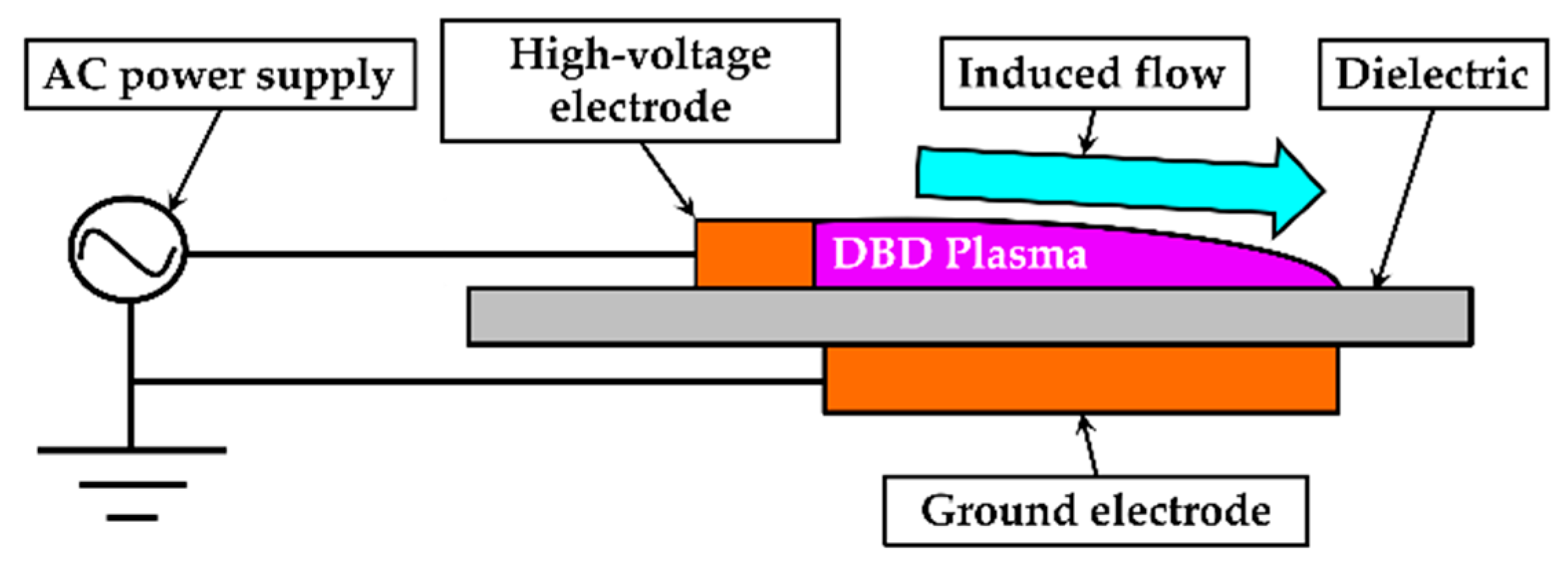
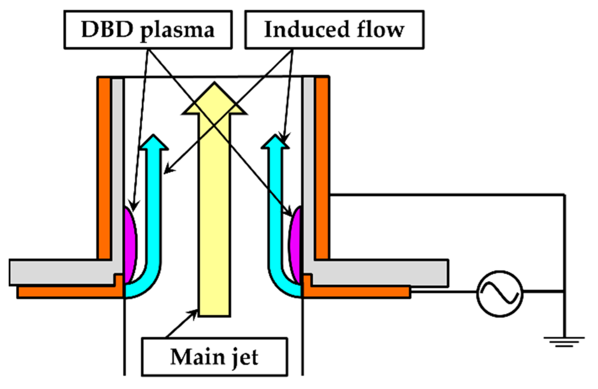
Applying a high-voltage AC to the high-voltage-applied electrodes of the DBD-PA generated a dielectric barrier discharge on the inner wall surface of the nozzle, inducing flow in the same direction as the jet flow (
Figure 4).
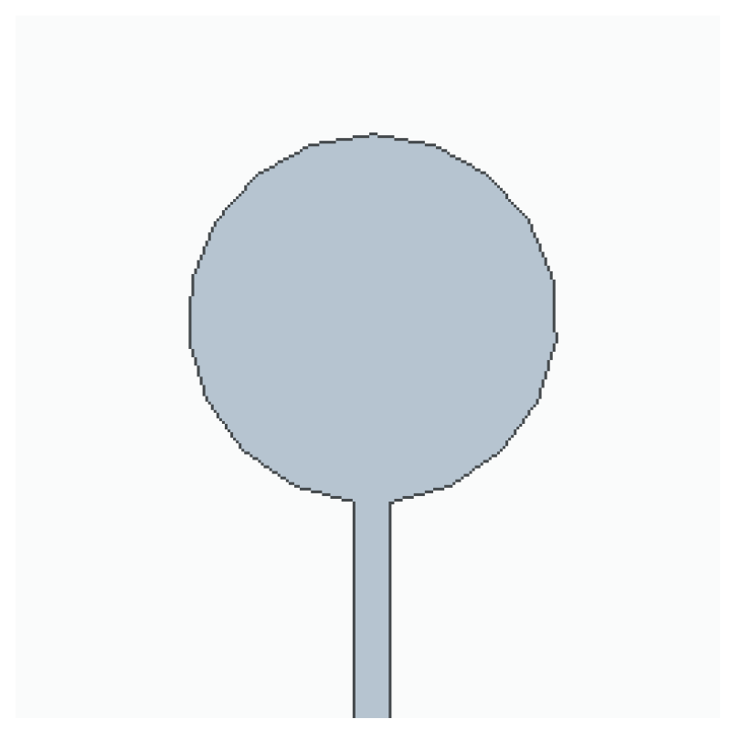
Figure 5 shows the disk-type bluff body installed at the upper part of the nozzle exit. The bluff body was disk-shaped with an outer diameter of 10 mm and a thickness of 2 mm. The device included a pillar with a width of 1 mm to be installed at the top of the nozzle.
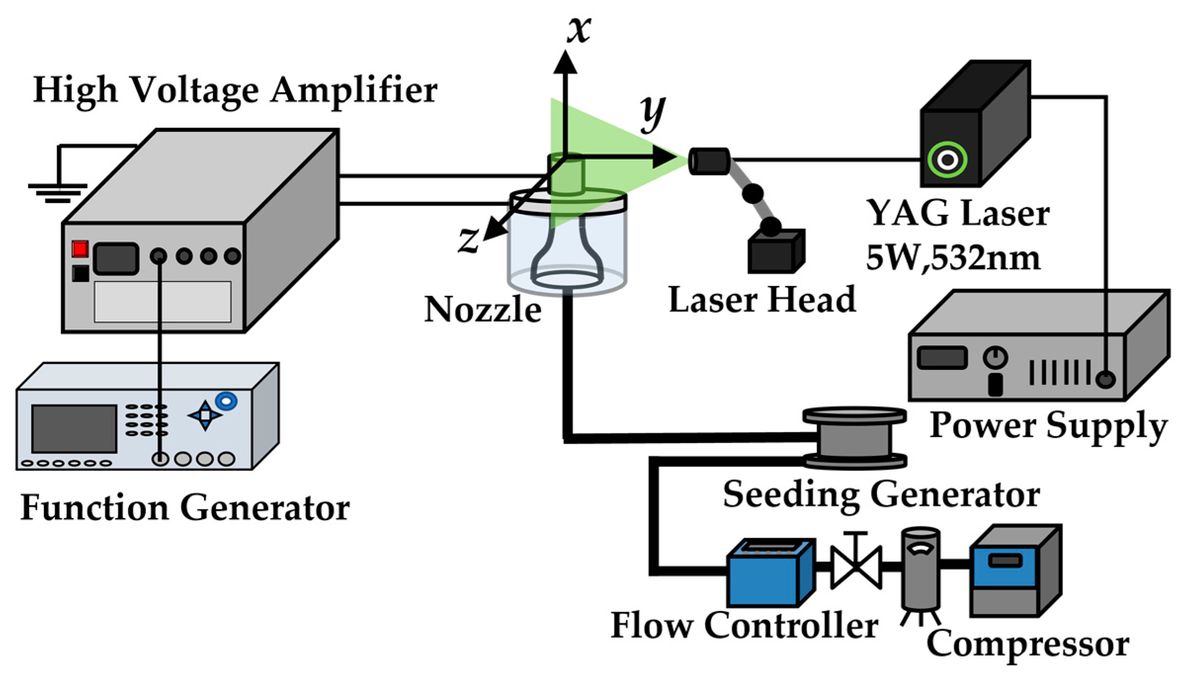
Figure 6 depicts a schematic of the experimental setup. Air was supplied from a compressor, the flow rate was adjusted using a mass flow controller, and the air was passed through a straightening tube with an inner diameter of 31 mm and length of approximately 0.85 m, to straighten the flow. Then, the converging nozzle with the DBD-PA nozzle attached at the tip (
Figure 3) ejected the jet vertically upward. The main flow direction of the jet was defined as the
x-axis, the nozzle radius direction as the
y-axis, and the direction perpendicular to them as the
z-axis. The DBD-PA was driven by outputting the signal of the voltage waveform applied to the DBD-PA from a function generator, amplifying the voltage with a large high-voltage power supply, and applying it to the DBD-PA. The jet cross-section was visualized by mixing tracer particles of DEHS (di-ethylhexyl sebacate) oil ejected by a seeding generator into the jet, illuminating them using an Nd:YAG laser using the laser light sheet method, and photographing them using a high-speed camera. Here, the particle size of the tracer particles was approximately 1 μm [
23]. As shown in
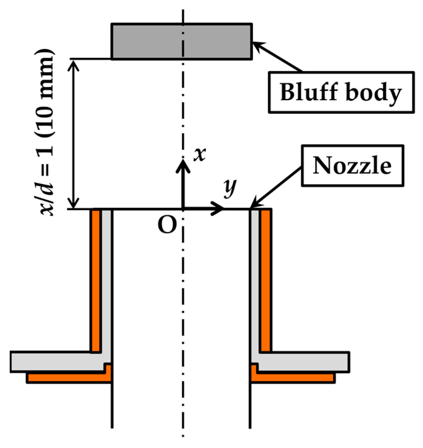
Figure 7, the bluff body was installed parallel to the nozzle at a distance of
x/
d = 1 from the nozzle exit. The origins of the
x,
y, and
z axes were the center of the nozzle at the nozzle tip.
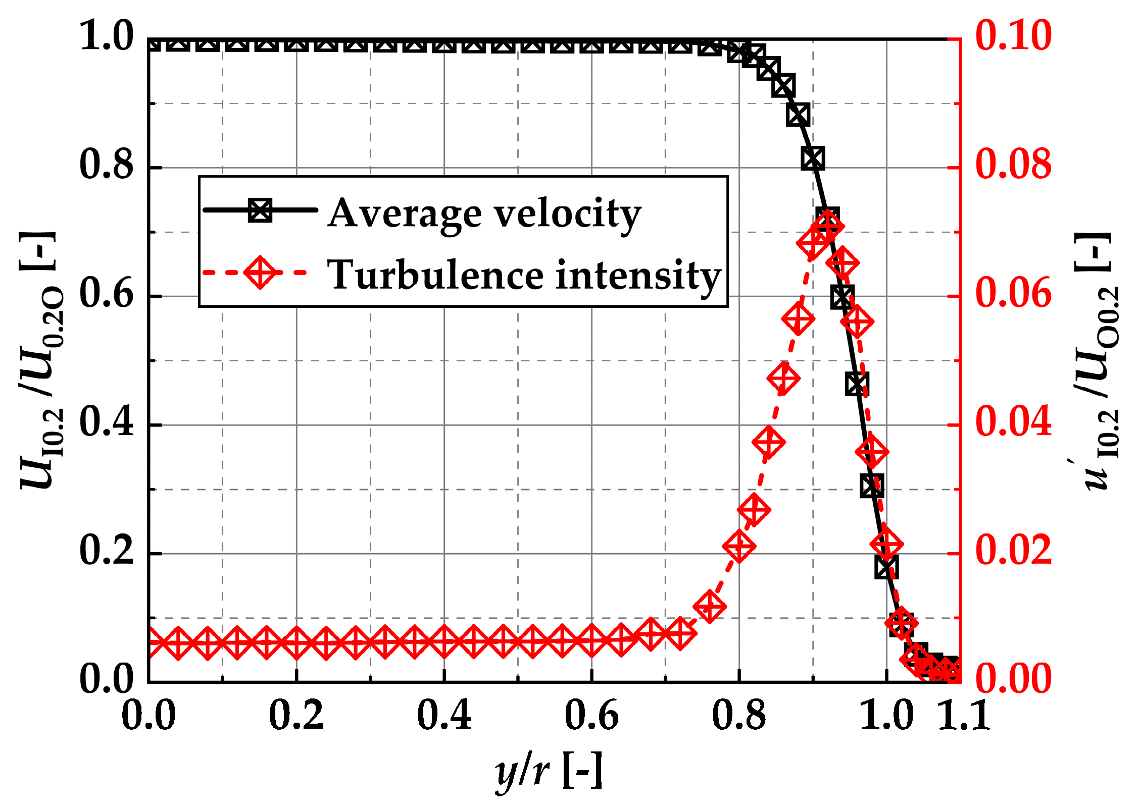
Figure 8 shows the average nozzle exit velocity
UI0.2 and the turbulence intensity
u’I0.2 distribution at
x/
d = 0.2 for a free jet (without the bluff body and not driving the DBD-PA). Measurements were taken at 0.2 mm intervals from
y/
r = 0–0.8 and at 0.1 mm intervals from
y/
r = 0.8–1.1 by moving a hot-wire anemometer along the
y-axis. Here, the measurement time of the hot-wire anemometer was 10 s per measurement point, the data rate was 20 kHz, and
U0.2O was the nozzle center velocity at
x/
d = 0.2. The sensor shape and calibration method of the hot-wire anemometer used in this study are described below. The sensor shape of the hot-wire anemometer was I-type, with a linear tungsten wire of 5 μm diameter and 1 mm length coated with Ni. The heating ratio was set to 1.6. The hot-wire anemometer was calibrated at
x/
d = 0.5 on the nozzle center axis of the free jet, to measure the velocity using a two-dimensional laser Doppler velocimeter capable of measuring absolute velocity.
4. Experimental Conditions
The experiment was conducted at an average jet exit velocity
UA = 10 m/s (Re ≈ 6600), which was calculated from the cross-sectional area of the nozzle exit and the jet flow rate. The DBD-PA was burst-driven.
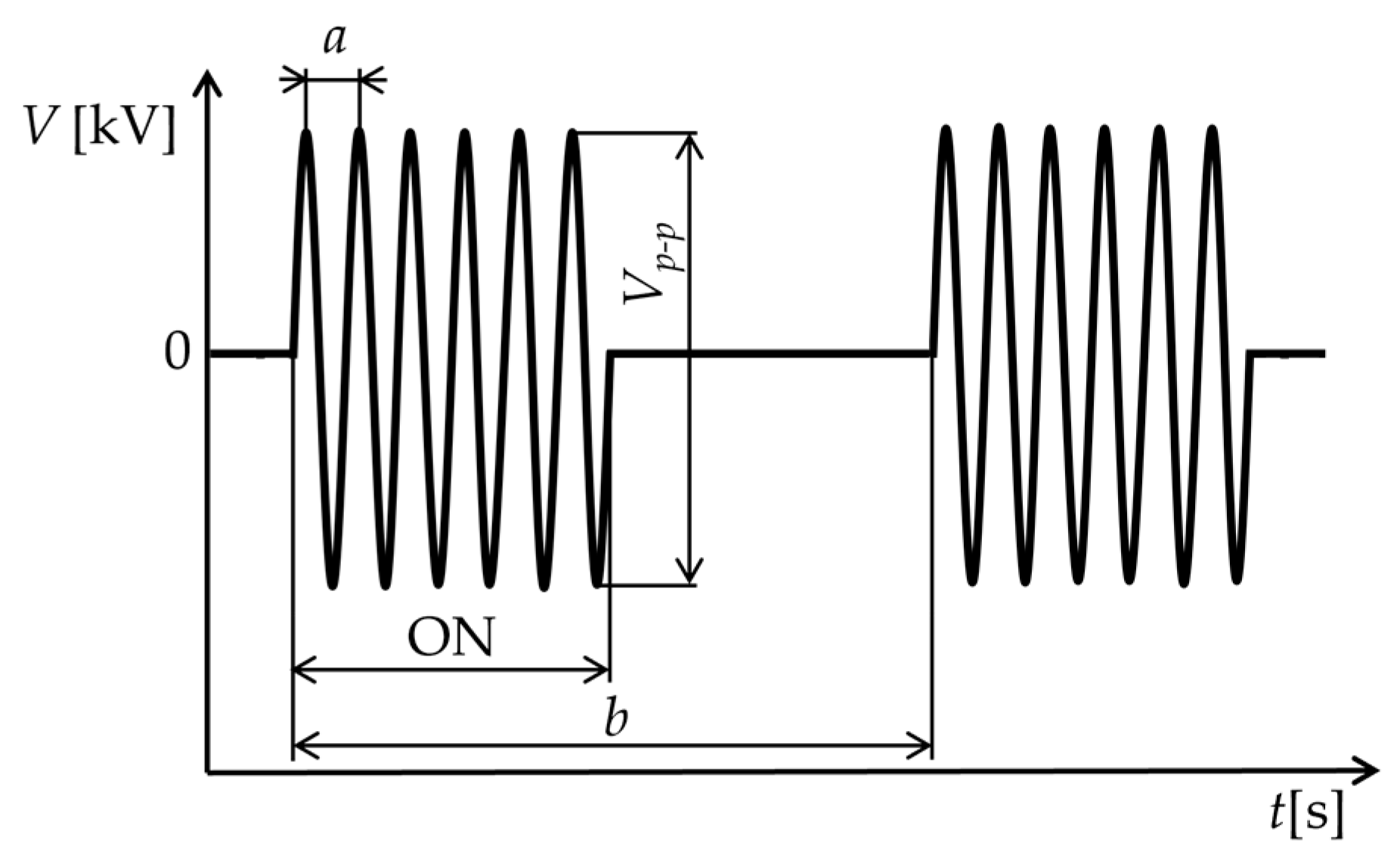
Figure 9 shows a schematic of the burst wave applied to the DBD-PA. Here, the driving frequency
fdrive and burst frequency
fburst were defined by Equations (1) and (2) using the symbols
a and
b shown in
Figure 9.
The burst ratio was the ratio of the burst cycle
b to the time during which the voltage was applied within
b and was set to 50% for all experimental conditions. In general, when a burst wave is applied to a DBD-PA, an induced flow occurs during the application of the voltage, and the induced flow decelerates when the voltage is not applied [
17]. Therefore, in burst driving, the frequency at which the induced flow occurs can be controlled by
fburst. Here, the base driving frequency of
fdrive was 7 kHz. The voltage waveform applied to the DBD-PA for this experiment was a sine wave. The driving voltage
Vp-p was set to
Vp-p = 16 kV for all driving conditions.
In this study, the following were carried out when the burst frequency of the DBD-PA changed.
- i.
Clarifying the changes in the vortice frequency generated in the jet.
From the video of the jet cross-section visualized using the laser light sheet method, the vortices generated at x/d = 1 near the bluff body installation position were counted, and the vortex generation frequency fvortex was determined. The high-speed camera’s frame rate was 20,000 fps, the data volume for counting vortex generation was 0.1 s (2000 frames), and the vortex generation frequency fvortex was calculated;
- ii.
Clarifying the changes in jet velocity and vorticity distributions near the bluff body.
Visualization photography of the jets up to
x/
d = 2.2 was performed, and particle image velocimetry (PIV) analysis was conducted. To perform PIV analysis, the jet nozzle was surrounded by a transparent acrylic box (400 × 500 × 700 mm
3) much larger than the nozzle diameter and filled with tracer particles. Visualization photography was performed by ejecting the jets. The high-speed camera’s frame rate was 70,000 fps, and analysis was performed on 1 s of images (70,000 pairs). The analysis was performed using PIV analysis software (Flownizer2D Ver.1.2.12) and the iterative image deformation method [
24]. The PIV interrogation window size was 20 pixels × 20 pixels for the first step, 14 pixels × 14 pixels for the second step, and 10 pixels × 10 pixels (0.53 × 0.53 mm
2) for the third step. The analysis was performed three times in each step to deform the image. In addition, adjacent interrogation windows overlapped by 50%. When the fluid advection velocity was 10 m/s, the image in the interrogation window moved approximately three pixels between the first and second times. Postprocessing PIV analysis (removal of erroneous vectors, among others) involved removing vectors with correlation coefficients less than 0.4, replacing the removed vectors with the average of the surrounding eight neighboring vectors, and smoothing each vector using the average of its eight neighboring vectors;
- iii.
Clarifying the changes in the vortex ring merging process.
The velocity was measured using a hot-wire anemometer, and the frequency of velocity fluctuations caused by vortices was determined using the continuous wavelet transform (CWT) of the obtained velocity time-series data. CWT was performed using a Morlet wavelet;
- iv.
The average flow rate and jet velocity distribution downstream of the bluff body.
The average flow rate was obtained from the flow velocity values measured by the hot-wire anemometer. The flow velocity was measured by traversing the hot-wire anemometer in the y-axis direction. Furthermore, the average velocity distribution downstream of the bluff body was clarified through PIV analysis. PIV analysis was performed using a double-pulse laser, and visualization photography was performed at 62.5 fps with a high-speed camera, analyzing 10 s of images (625 pairs). The time interval between the first and second images in a pair was 0.020 ms. The PIV analysis method and postprocessing were the same as in part ii, but the PIV interrogation window size was 32 pixels × 32 pixels for the first step, 24 pixels × 24 pixels for the second step, and 16 pixels × 16 pixels (1.03 × 1.03 mm2) for the third step. When the fluid advection velocity was 10 m/s, the image in the interrogation window moved approximately three pixels between the first and second instances.
5. Experimental Results
5.1. Changes in the Frequency of Vortices Generated in Jets
The effects of altering the
fburst values of a Dielectric Barrier Discharge Plasma Actuator (DBD-PA) to generate vortices in the jet’s initial stage, which subsequently influenced the jet’s diffusion, were evaluated. The vortex generation frequency
fvortex was determined by visualizing the jet cross-section using the laser light sheet method and counting the vortices generated at
x/
d = 1 near the bluff body installation position in the video. Visualization photography was performed by aligning the laser light sheet so that it could pass through the center of the nozzle and the bluff body, and a high-speed camera was placed parallel to the laser light sheet.
Table 1 summarizes the experimental conditions used to determine
fvortex, and
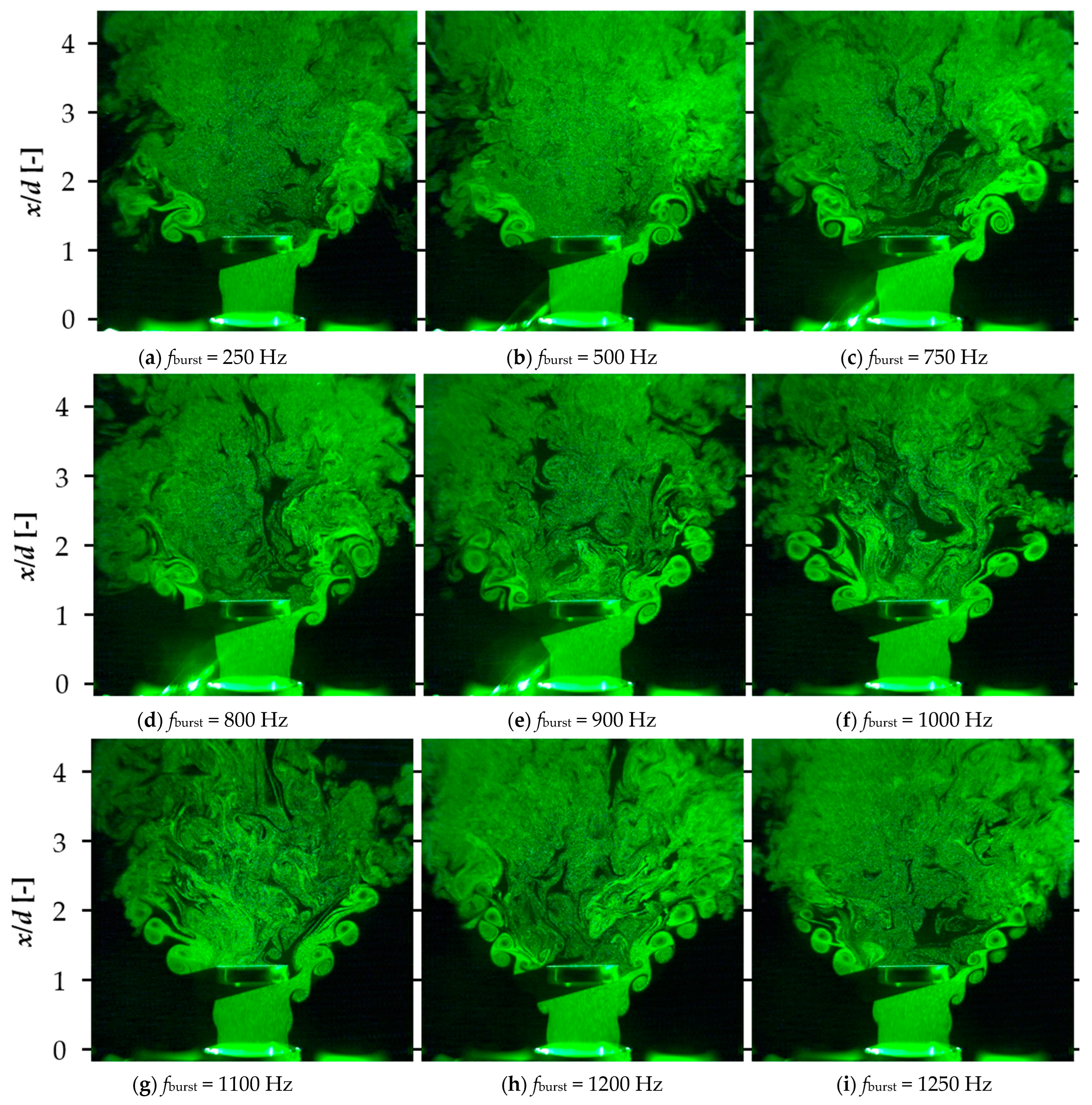
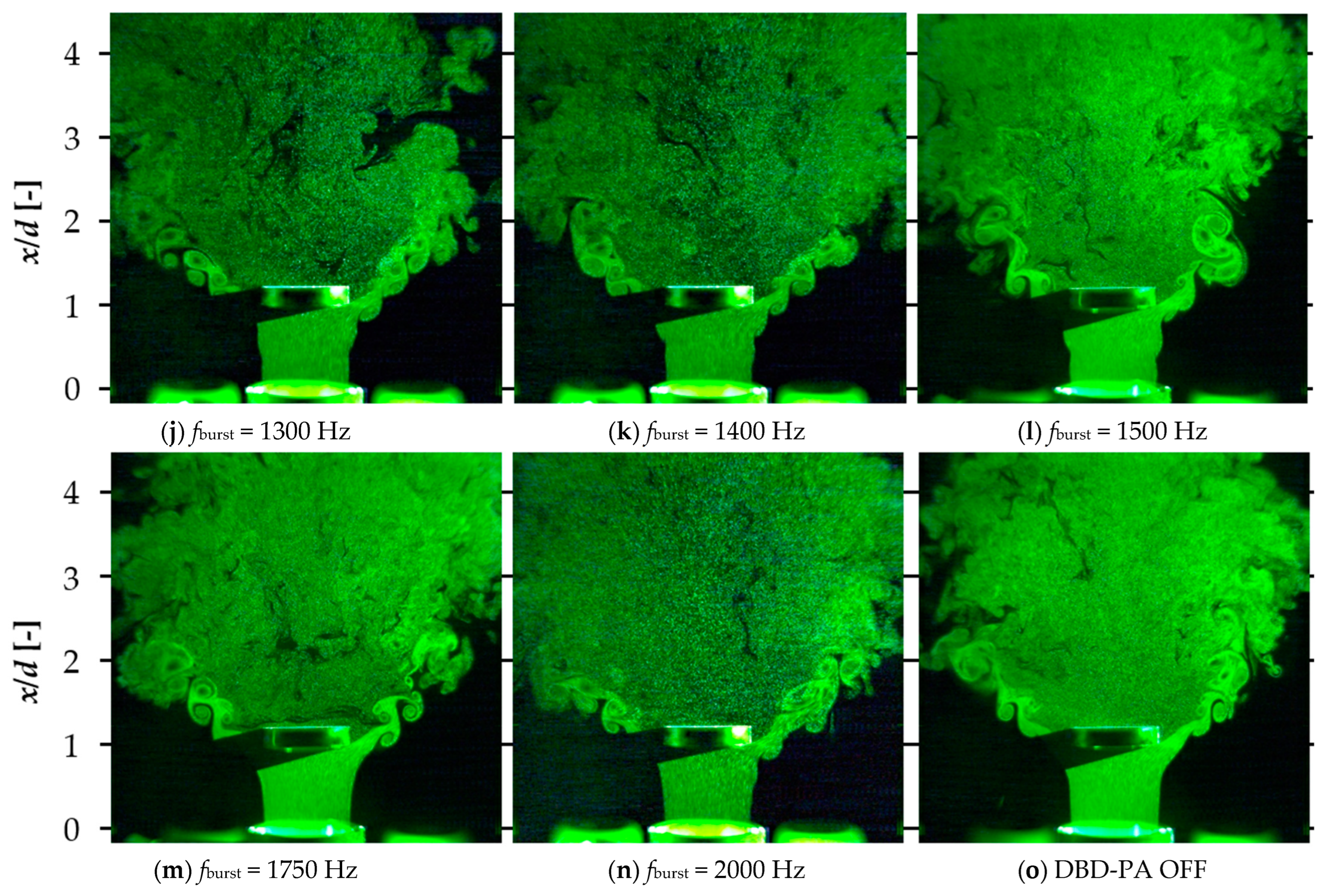
Figure 10 shows the jet control results at the
fburst values given in
Table 1. The
fdrive was determined to be divisible by the frequency of
fburst or to have a decimal point of 0.5 when divided by
fburst, so that the AC waveform was not interrupted in the middle.
Figure 10 shows that the vortices generated near the bluff body consisted of vortices generated on the outer periphery of the jet and vortices generated in the opposite directions to those. When the jet collided with the bluff body and advected radially, a velocity distribution in the boundary layer formed on the surface of the bluff body, resulting in vorticity. Therefore, it is considered that the vorticity generated counter-rotating vortices. After impinging on the bluff body, the jet flow spread radially, resulting in a larger jet width and a slower average velocity downstream than a jet flow without a bluff body. In addition, because the back of the bluff body was under negative pressure, a recirculation flow was generated, which caused the downstream flow to return upstream. This recirculation flow suppressed the jet diffusion. To promote jet diffusion, controlling the jet using the DBD-PA to ensure that it was not entrained by the recirculation flow was necessary.
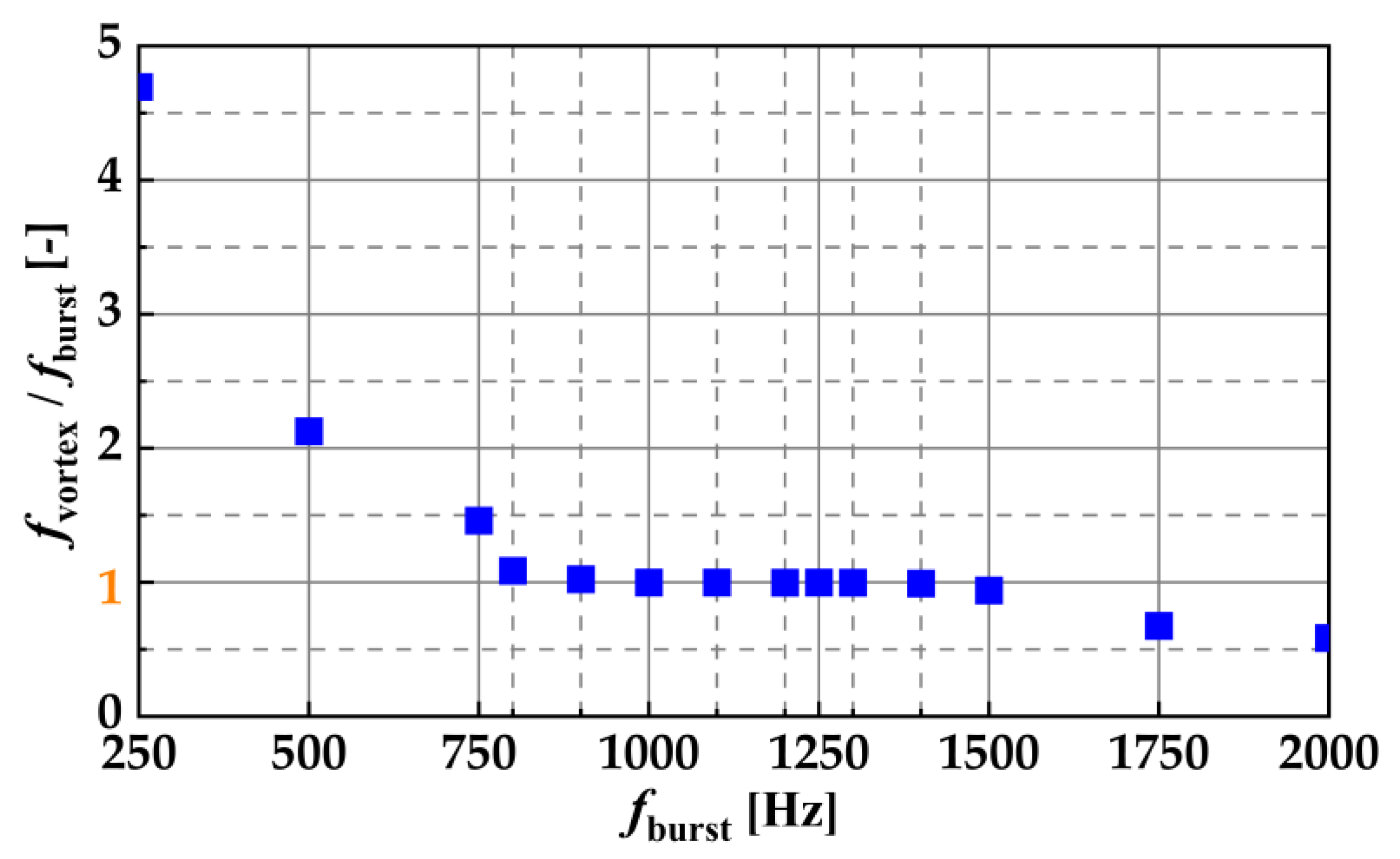
Figure 11 shows the results of
fvortex determination. Similarly, the natural frequency
fn of vortex generation in the initial jet region when the DBD-PA was off was determined by counting 0.1 s of data. Here,
fvortex and
fn were determined by counting the vortices on the outer peripheral of the jet. The natural frequency was
fn = 1098 Hz.
Figure 11 shows that
fburst = 900–1400 Hz resulted in
fburst =
fvortex. At
fburst = 900–1400 Hz, a lock-in phenomenon occurred, in which the frequency of the flow excitation induced by the DBD-PA was synchronized with the frequency of the vortices generated on the outer periphery of the jet. Therefore, under lock-in conditions, vortex generation was controlled by the burst frequency, and vortices were generated at regular intervals. Under burst conditions in which lock-in occurred, the frequency of vortices generated by the DBD-PA could be controlled. In our previous studies, we showed that the lock-in phenomenon occurred when a jet without a bluff body was controlled by a DBD-PA [
15]. Here, it was clarified that the lock-in phenomenon occurred when the jet with the bluff body was controlled by the DBD-PA.
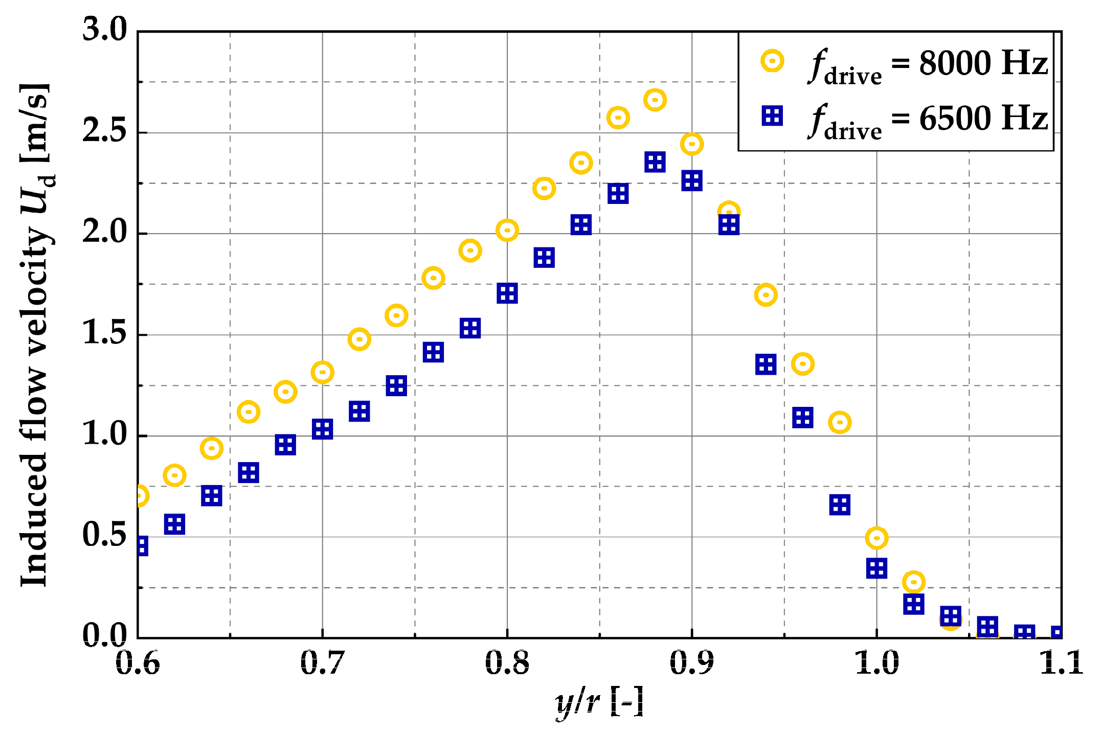
The induced flow velocity varied with the frequency of
fdrive: the higher the frequency of
fdrive, the higher the induced flow velocity, and the lower the frequency of
fdrive, the lower the velocity. On the basis of the experimental conditions shown in
Table 1, the induced flow velocity distribution
Ud at
x/
d = 0.2 was measured for
fdrive = 8000 Hz, the highest frequency of
fdrive, and
fdrive = 6500 Hz, the lowest frequency. The results of these measurements are shown in
Figure 12. Here, measurements were taken by moving the hot-wire anemometer along the
y-axis. The measurement time of the hot-wire anemometer was 10 s per measurement point, the data rate was 20 kHz.
Figure 12 shows that the difference in the maximum flow velocity for
Ud differed by approximately 0.3 m/s between
fdrive = 8000 Hz and
fdrive = 6500 Hz. In our previous study, we controlled the jet flow at
Re = 5000 by driving the DBD-PA at
Vp-p = 16 kV and
Vp-p = 12 kV, where the maximum induced flow velocity differed by approximately 2 m/s. Despite this difference, there was no variation in the burst frequency at which the lock-in phenomenon occurred. Therefore, although the induced flow velocity
Ud in this study differed by approximately 0.3 m/s depending on the
fburst, its effect on the jet control results was considered minimal.
5.2. Changes in Jet Velocity and Vorticity Distribution near the Bluff Body
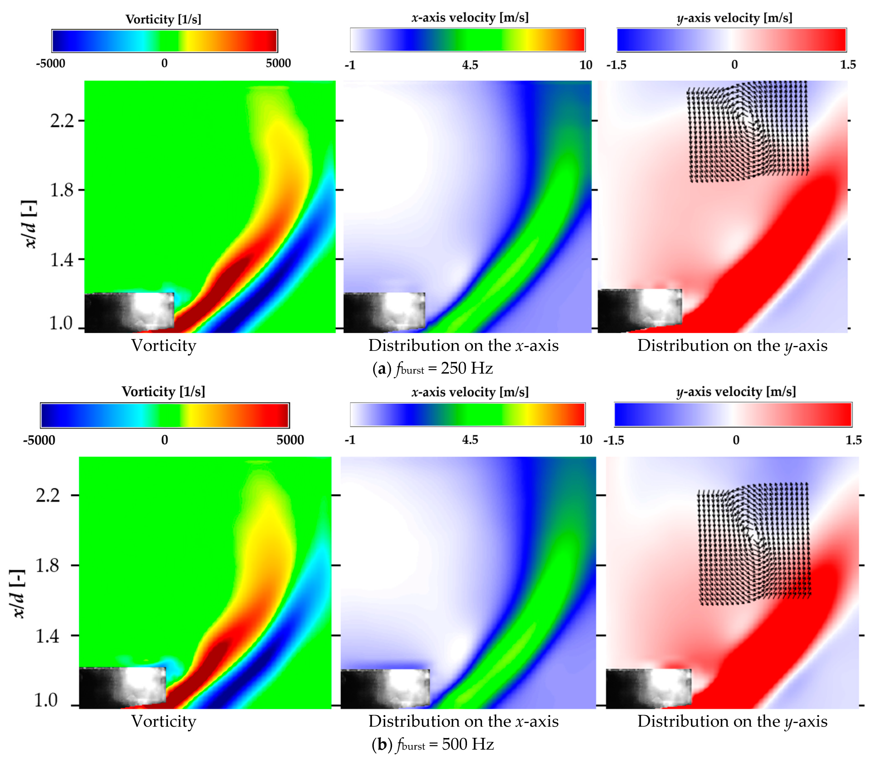
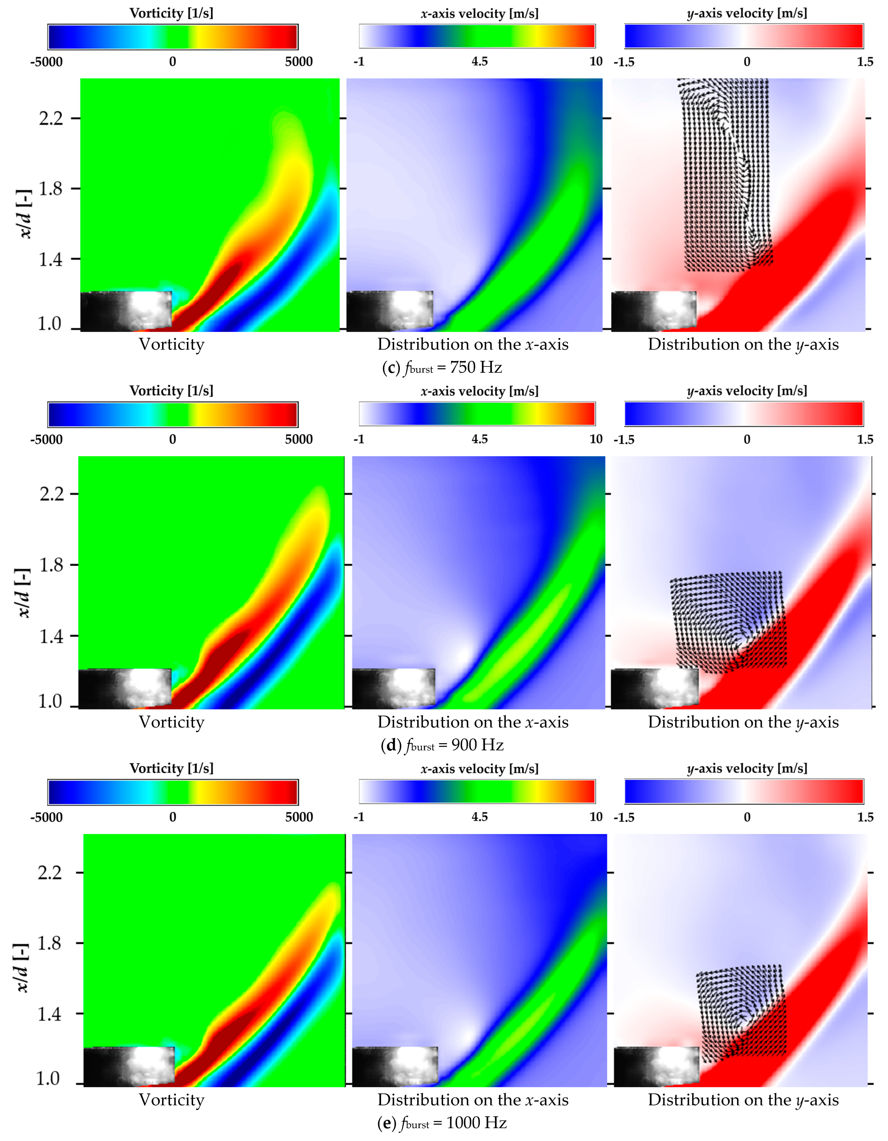
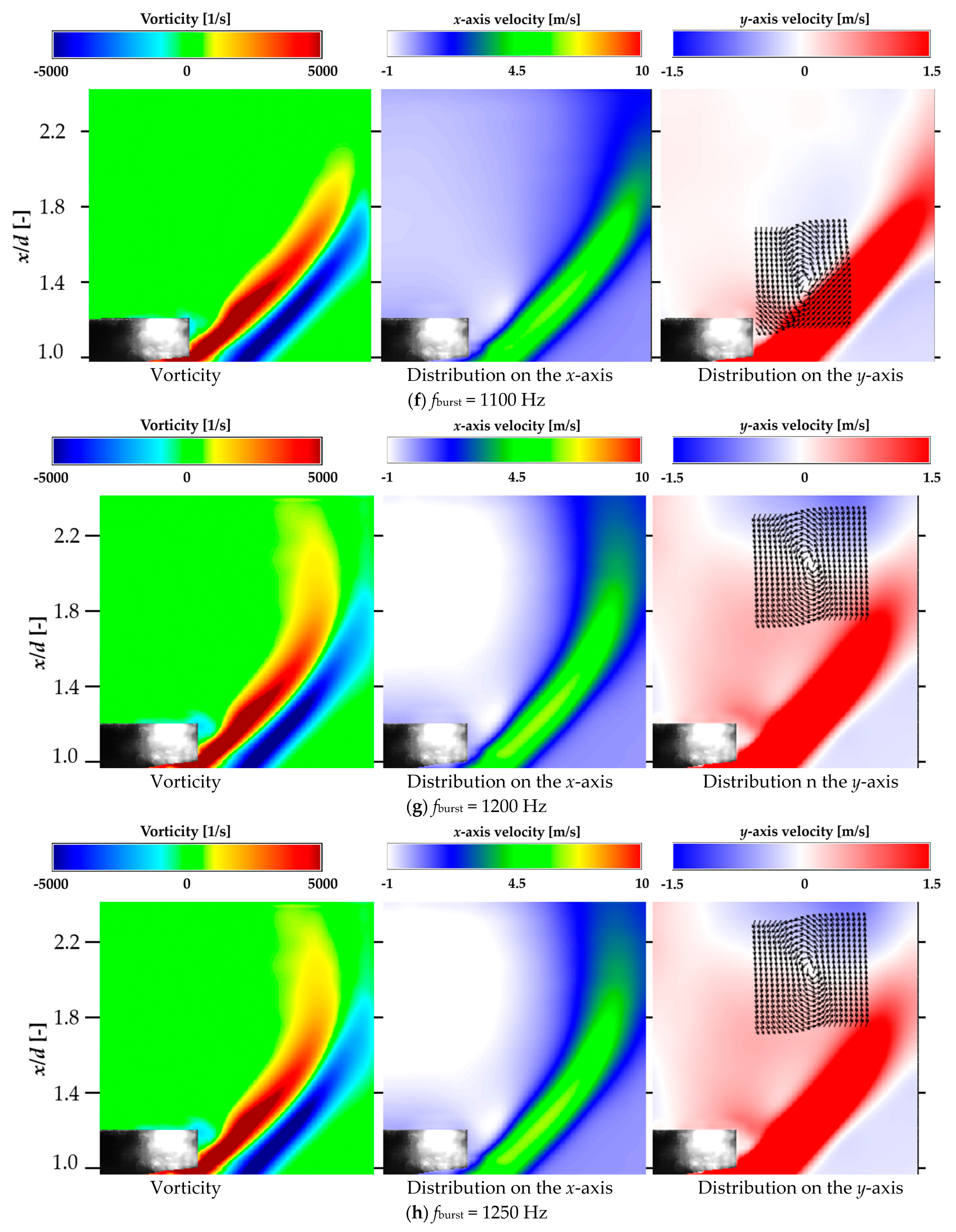
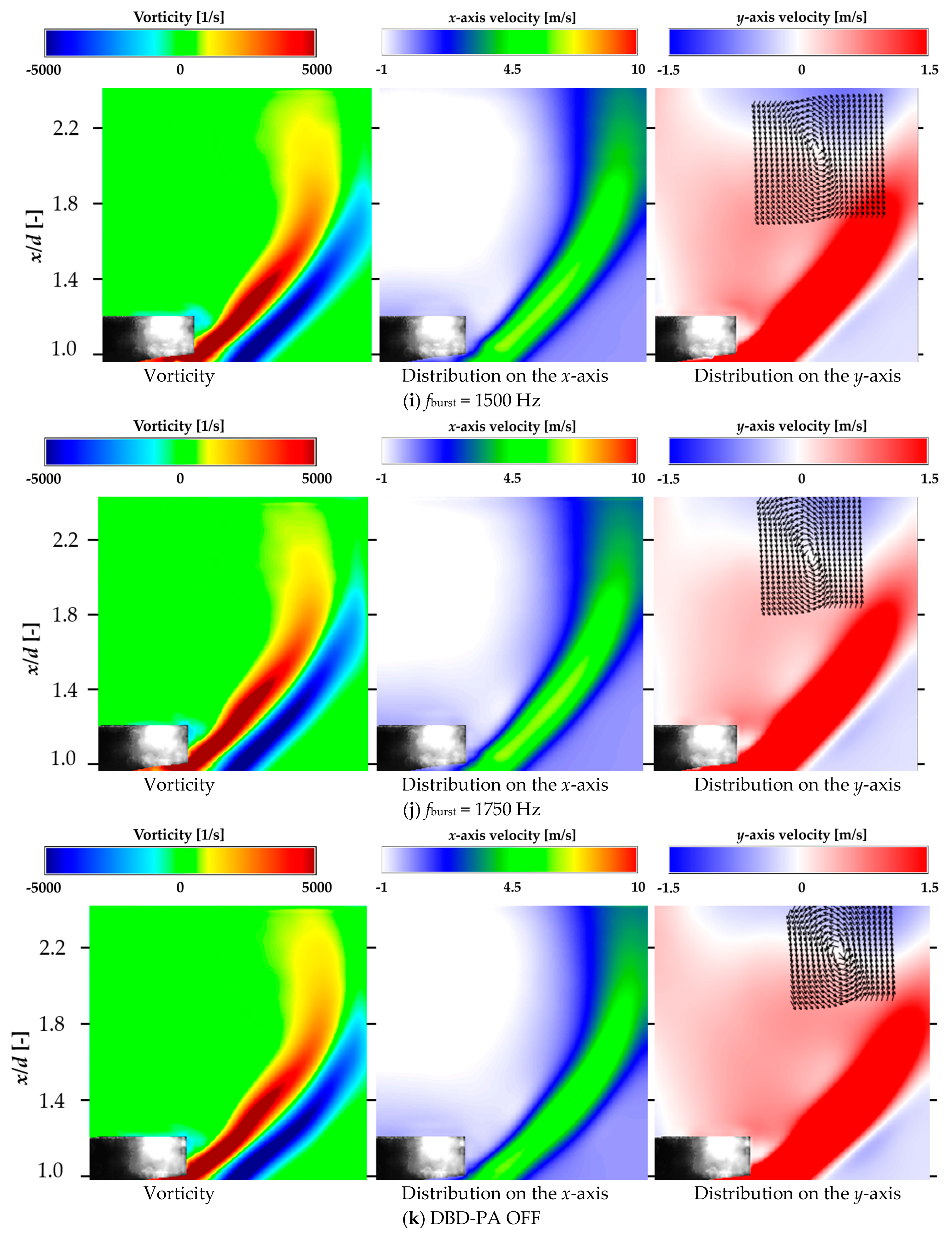
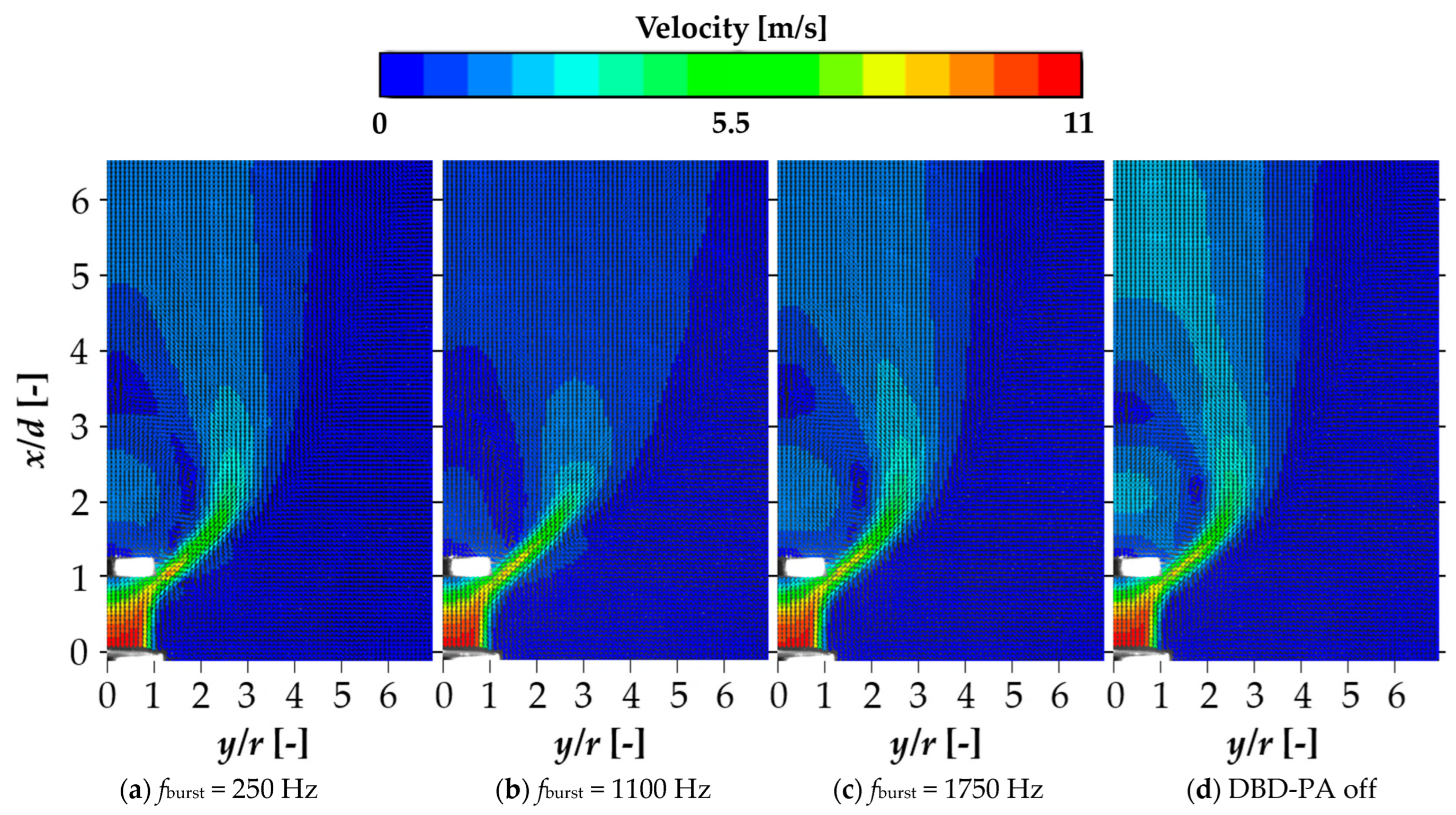
This section clarifies how the flow near the bluff body changed with the driving frequency of the DBD-PA.PIV analysis of the jet near the bluff body was conducted with the DBD-PA off, at burst frequencies at which the lock-in phenomenon occurred, at burst frequencies lower than those at which the lock-in phenomenon occurred, and at higher burst frequencies. The conditions for performing PIV analysis are listed in
Table 2, and the results of the PIV analysis up to approximately
x/
d = 2.2 from
x/
d = 1.0 are shown in
Figure 13. Each figure shows the average vorticity, average velocity on the
x-axis, and average velocity distribution along the
y-axis of the 1 s PIV analysis results. The average velocity distribution along the
y-axis also indicates the average velocity vector in the
xy direction at the position where the jet was entrained in the recirculation flow. For the circular jet, the PIV analysis results were obtained in the radial direction from the center of the nozzle.
Figure 13 shows that the average vorticity and
x-axis velocity distributions at frequencies near
fn (
fburst = 900–1100 Hz) were spread in the
y-axis direction (nozzle radius direction), indicating that the vortices were less likely to be entrained in the recirculation flow. The average vorticity and
x-axis velocity distributions on the recirculation flow side for the other DBD-PA driving conditions and with the DBD-PA off were curved along the recirculation flow formed on the downstream side of the bluff body, indicating that the vortices of the jet flow were entrained by the recirculation flow in the direction of narrowing of the jet width. In the
y-axis mean velocity distribution, a circulating (rotating) flow was generated from the mean velocity vector in the
xy direction at the position where the direction of the velocity on the
y-axis changed. For
fburst = 900–1100 Hz, the circulating flow occurred at approximately
x/
d = 1.4, whereas for other conditions, it occurred at approximately
x/
d = 2.
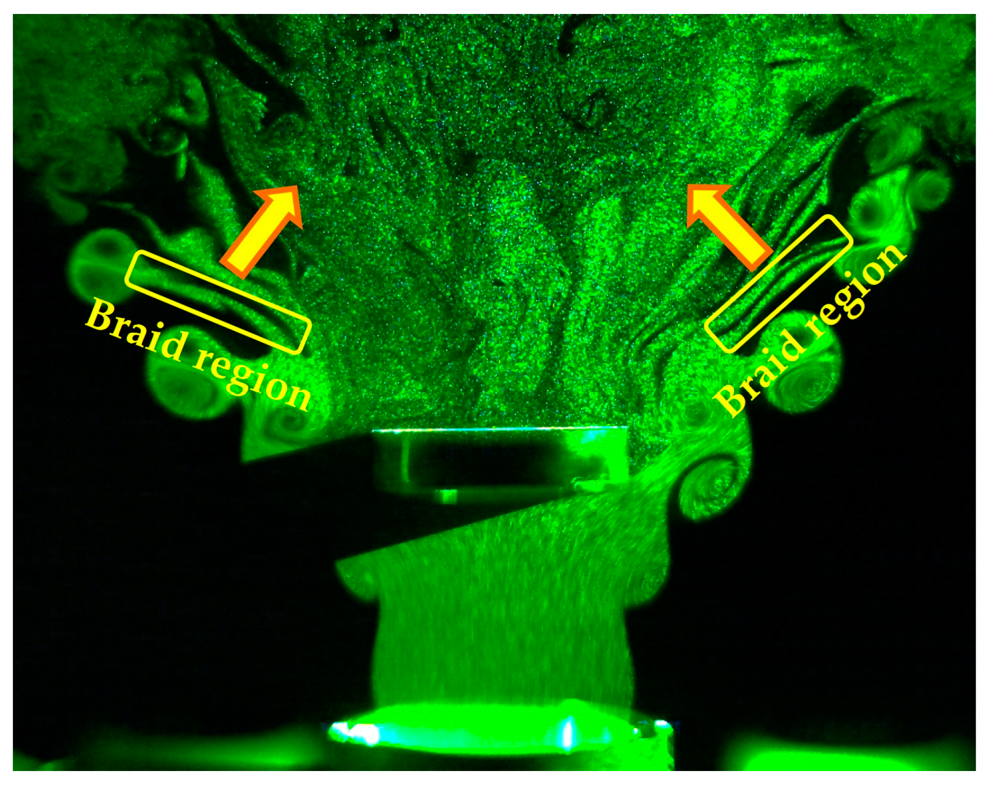
Figure 14 shows that for
fburst = 900–1100 Hz, the jet flow in the braid region between the vortices was entrained into the recirculation region at approximately 1.4, thereby forming the recirculation region.
At fburst = 750 Hz, the circulating (rotating) flow of the average velocity vector in the xy direction was longer in the x-axis direction than in the other conditions. fburst = 750 Hz was the frequency at which lock-in occurred. The circulating (rotating) flow of the average velocity vector was longer in the x-axis direction at fburst = 750 Hz because the frequency was close to the frequency at which the lock-in phenomenon occurred, and there was an instance at which the jet flow or vortex in the braid region between two vortices generated by the DBD-PA was caught in the recirculation region and the flow in which the merged vortex collapsed was caught in the recirculation region.
The lock-in phenomenon occurred at fburst = 900–1400 Hz, but the jet width expanded without being entrained into the recirculation flow at fburst = 900–1100 Hz. At fburst = 1200–1400 Hz, vortices were generated at regular intervals, but the short generation cycle of the vortices reduced the interval between them. It was observed that the vortices generated on the outer peripheral and recirculation sides of the jet merged and collapsed, and the flow after collapse was entrained into the recirculation flow.
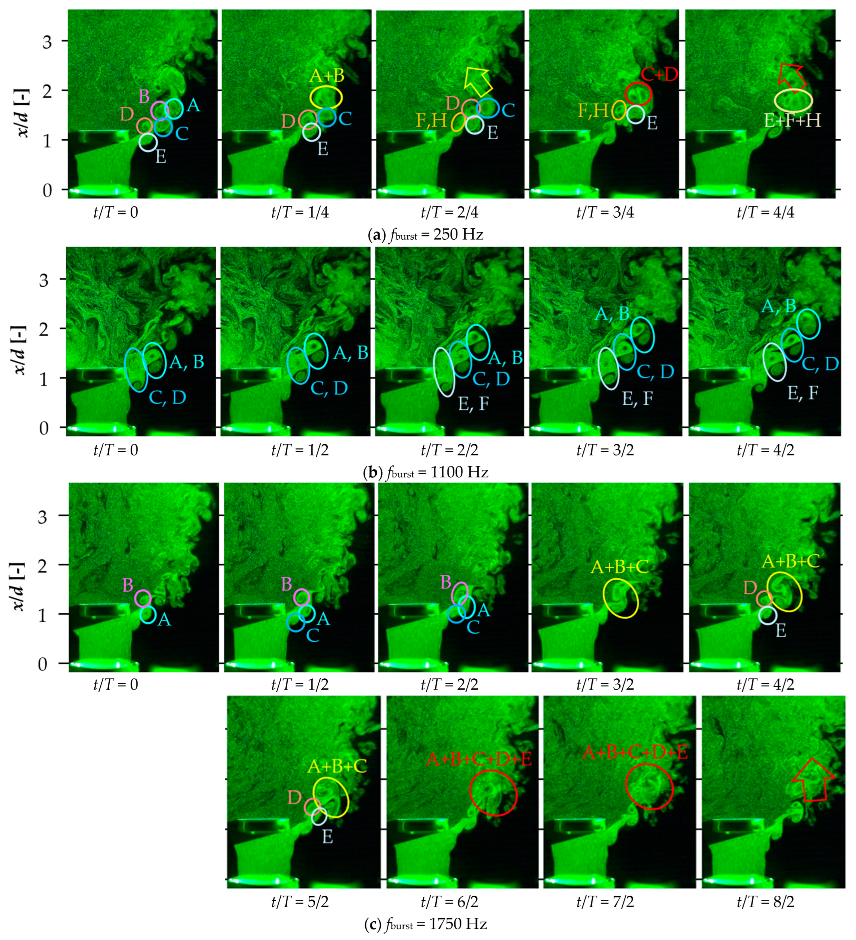
Figure 15 shows the time-series visualization images with the DBD-PA in off mode,
fburst = 250, 1100, and 1750 Hz. Here,
T is the time of one burst cycle under each DBD-PA driving condition,
t is the time with the first visualization image as the reference (zero),
T′ is the time of one cycle of
fn, and
t′ is the time with the first visualization image as the reference (zero). In
Figure 15, the vortices generated on the outer periphery of the jet are designated as A, C, and E, and those on the recirculation side are designated as B, D, F, and H.
As shown in
Figure 15, with the DBD-PA off and
fburst = 250, 1100, and 1750 Hz, the generation cycles of the vortices on the outer periphery of the jet and those on the recirculation side were unsteady and irregular. There were three vortex generation patterns, as follows: one vortex generated on the outer periphery of the jet with another on the recirculation side; one vortex generated on the outer periphery of the jet with two on the recirculation side (vortices F and H in
Figure 15a 250 Hz and B and D in
Figure 15d DBD-PA off); and finally, one vortex generated on the recirculation side with two generated on the periphery of the jet (vortices A and C in
Figure 15c 1750 Hz).
When the vortex interval was irregular, vortices generated downstream on the outer periphery of the jet and upstream on the recirculation side sometimes merged, and vortices generated in pairs on the outer periphery of the jet and on the recirculation side sometimes merged. In addition, three or more vortices could merge and collapse. Because the positive and negative vorticities of the vortices generated on the outer peripheral and recirculation sides were opposite, the merged vortices collapsed instead of developing. When vortices collapse, vortices diffuse and the jet is entrained into the recirculation flow, causing the jet to bend in a direction that does not expand its width to near x/d = 2, thereby hindering jet diffusion. Meanwhile, at fburst = 1100 Hz, the vortices generated on the outer periphery of the jet by the lock-in phenomenon occurred in the same cycle as fburst, and the vortices generated on the recirculation side also occurred at the same time as vortices on the outer periphery of the jet. Vortices generated on the outer peripheral and recirculation sides occurred at regular intervals, maintaining a constant interval and advecting downstream without merging. At fburst = 1100 Hz, the vortices did not merge or collapse downstream, making the jet less likely to be entrained into the recirculation flow and promoting jet diffusion by expanding the jet width.
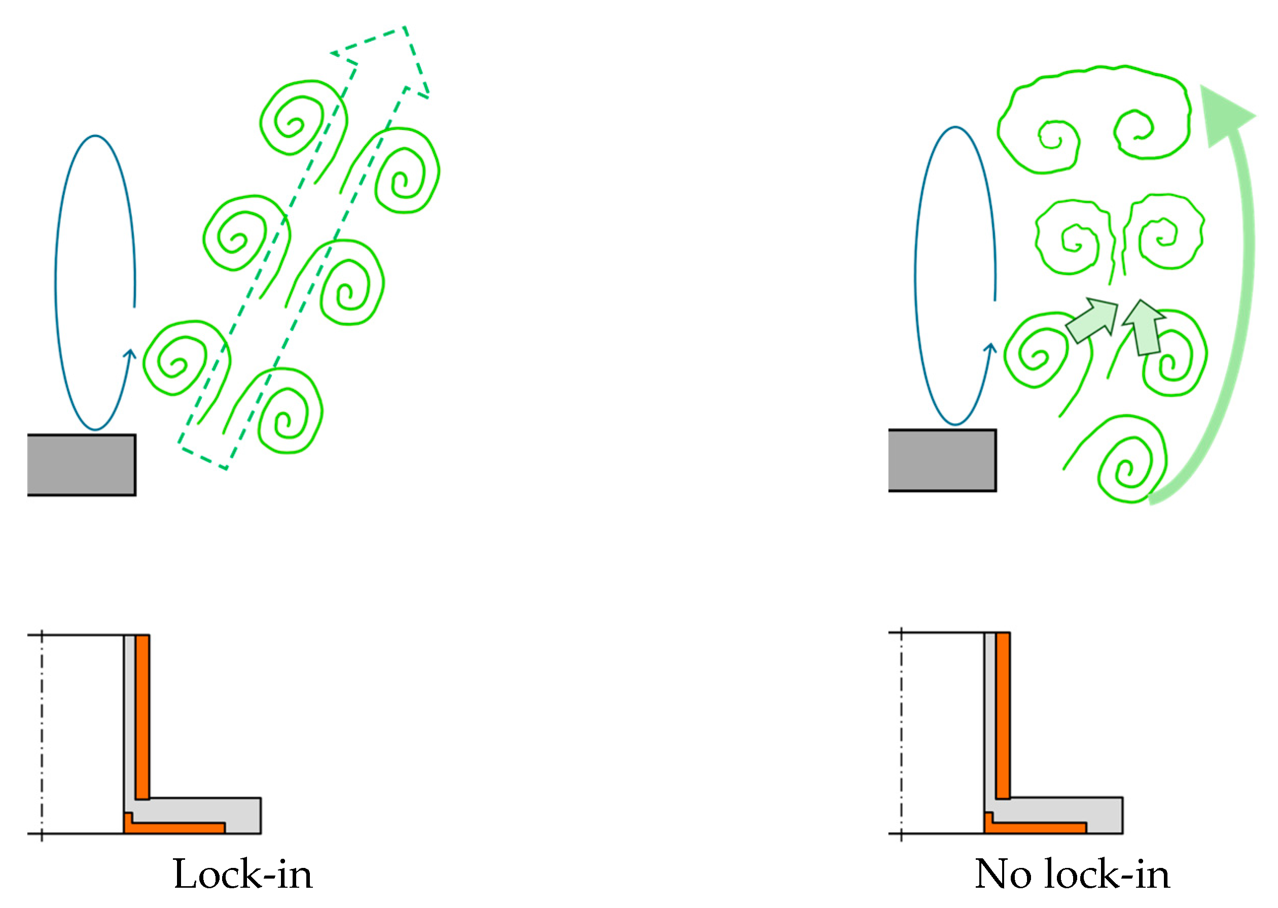
Figure 16 shows a schematic diagram to help comprehend the difference in vortex structure between conditions in which lock-in does and does not occur. Under conditions in which lock-in occurs, the vortices do not merge and reach the downstream and are not entrained in the recirculation flow. Under conditions in which lock-in does not occur, vortices are randomly generated and merge with each other. After merging and collapsing, the vortices diffuse, slowing the flow and becoming entrained in the recirculation flow.
5.3. Comparison of the Vortex Ring Merging Process
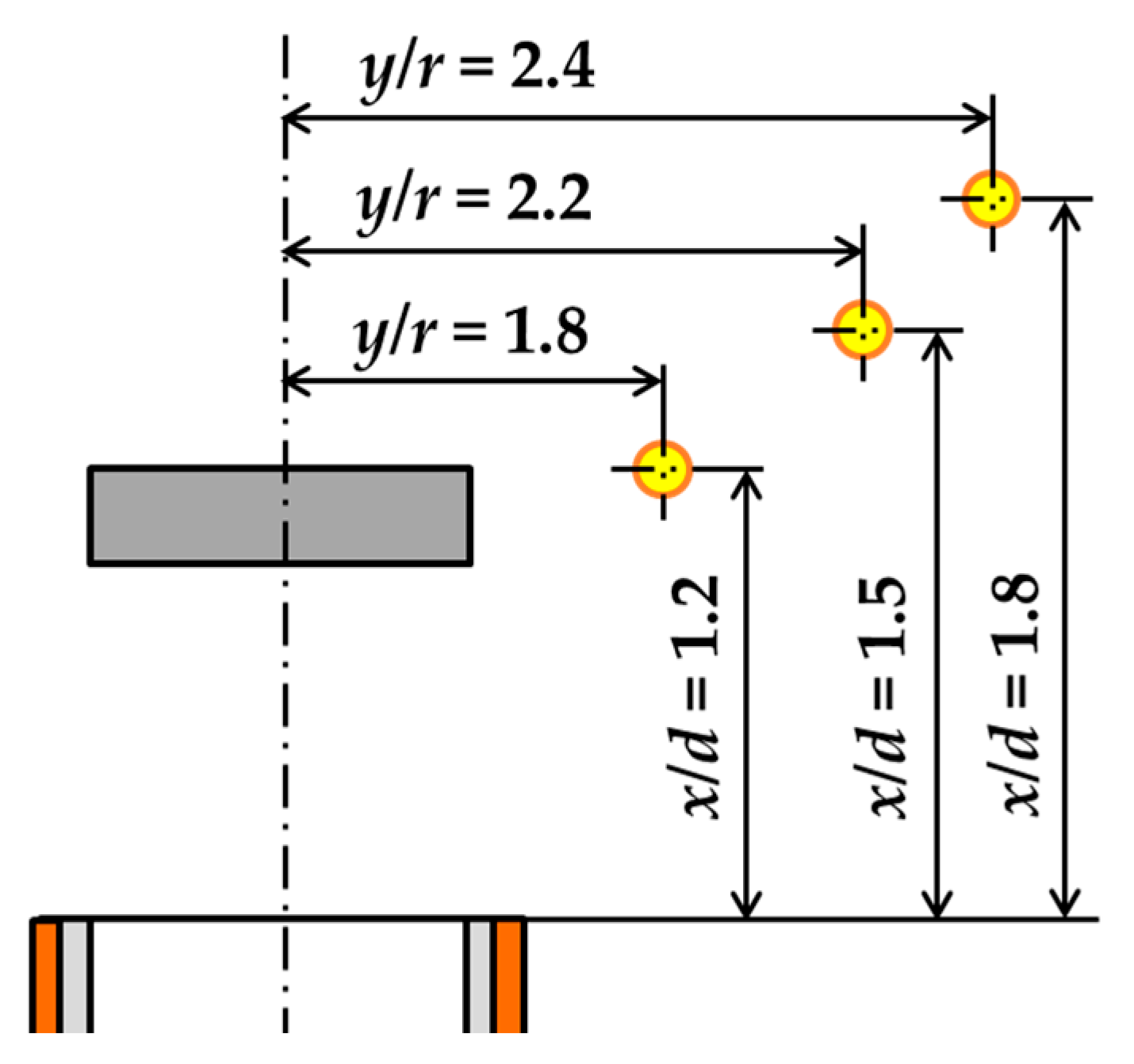
This section compares vortex ring-merging processes that affect the jet width in the radial direction of the nozzle. The comparison conditions were set to DBD-PA off and fburst = 250, 1100, and 1750 Hz. The vortex ring-merging processes were compared using scalograms obtained from the CWT of the velocity time-series data measured by an I-type hot-wire anemometer. Measurements were performed at x/d = 1.2, 1.5, and 1.8. The measurement positions in the y-axis direction were set to represent the average vorticity distribution of the PIV analysis at each measurement position.
Figure 17 shows the measurement points at which the flow velocity was measured for the CWT. The data rate at each measurement point was 20 kHz, and the measurement time was 10 s.
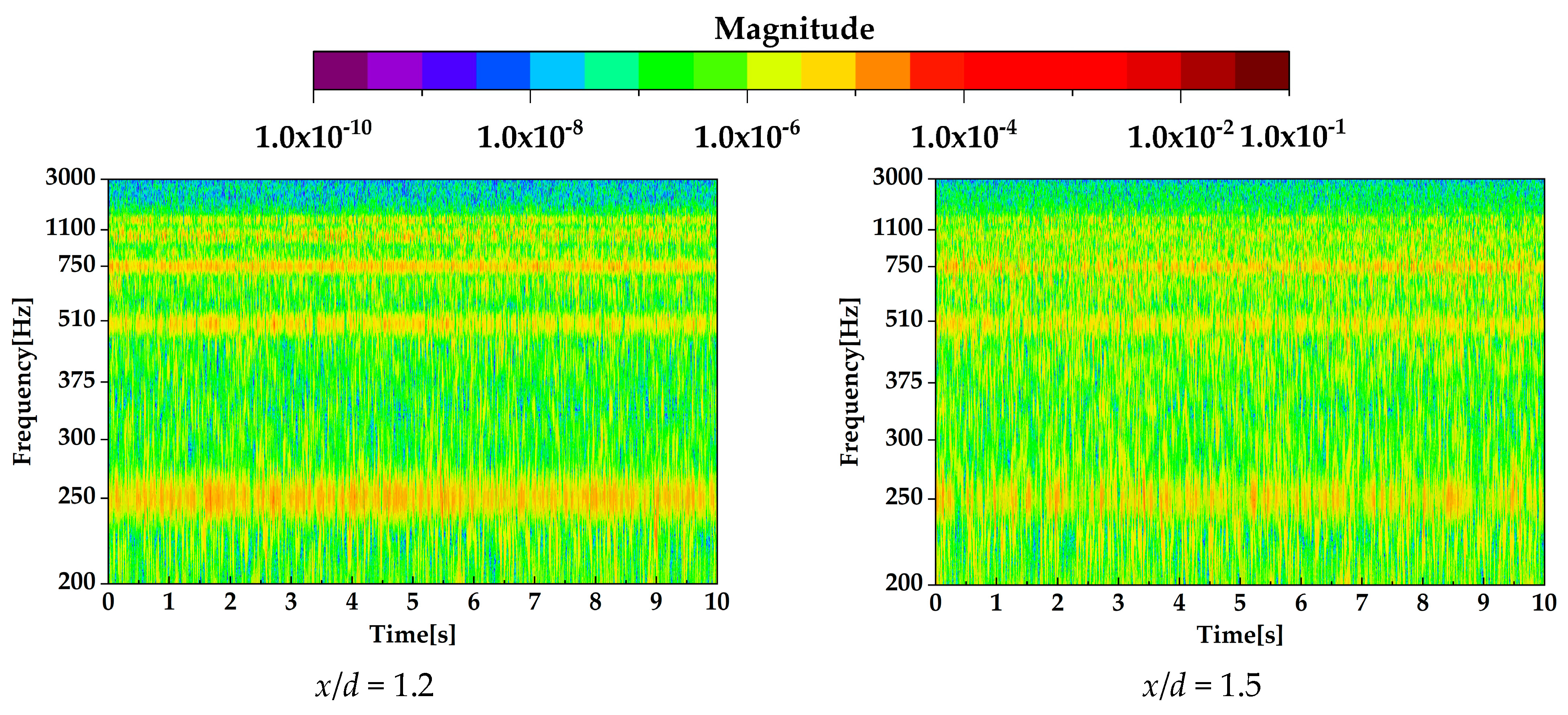
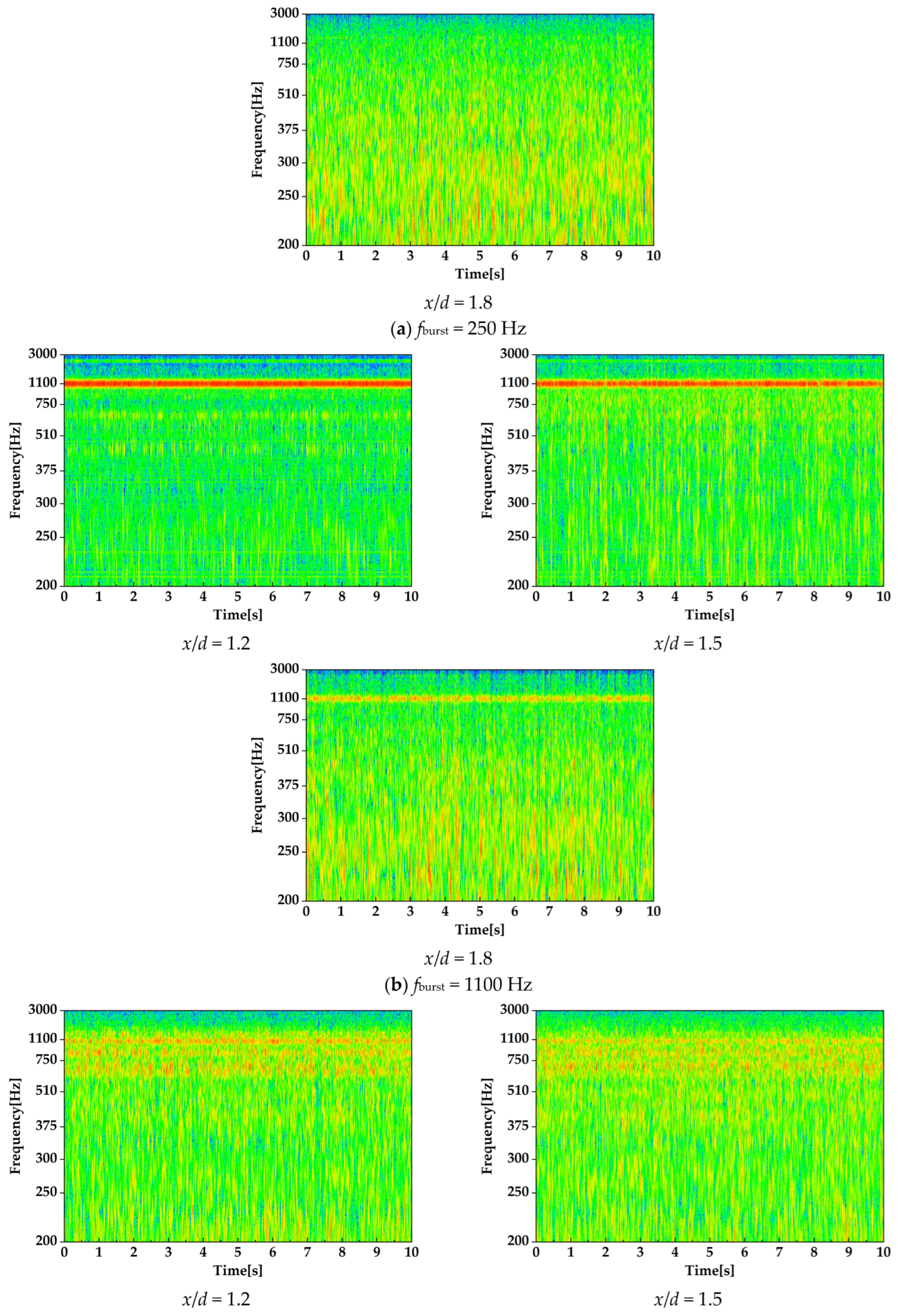
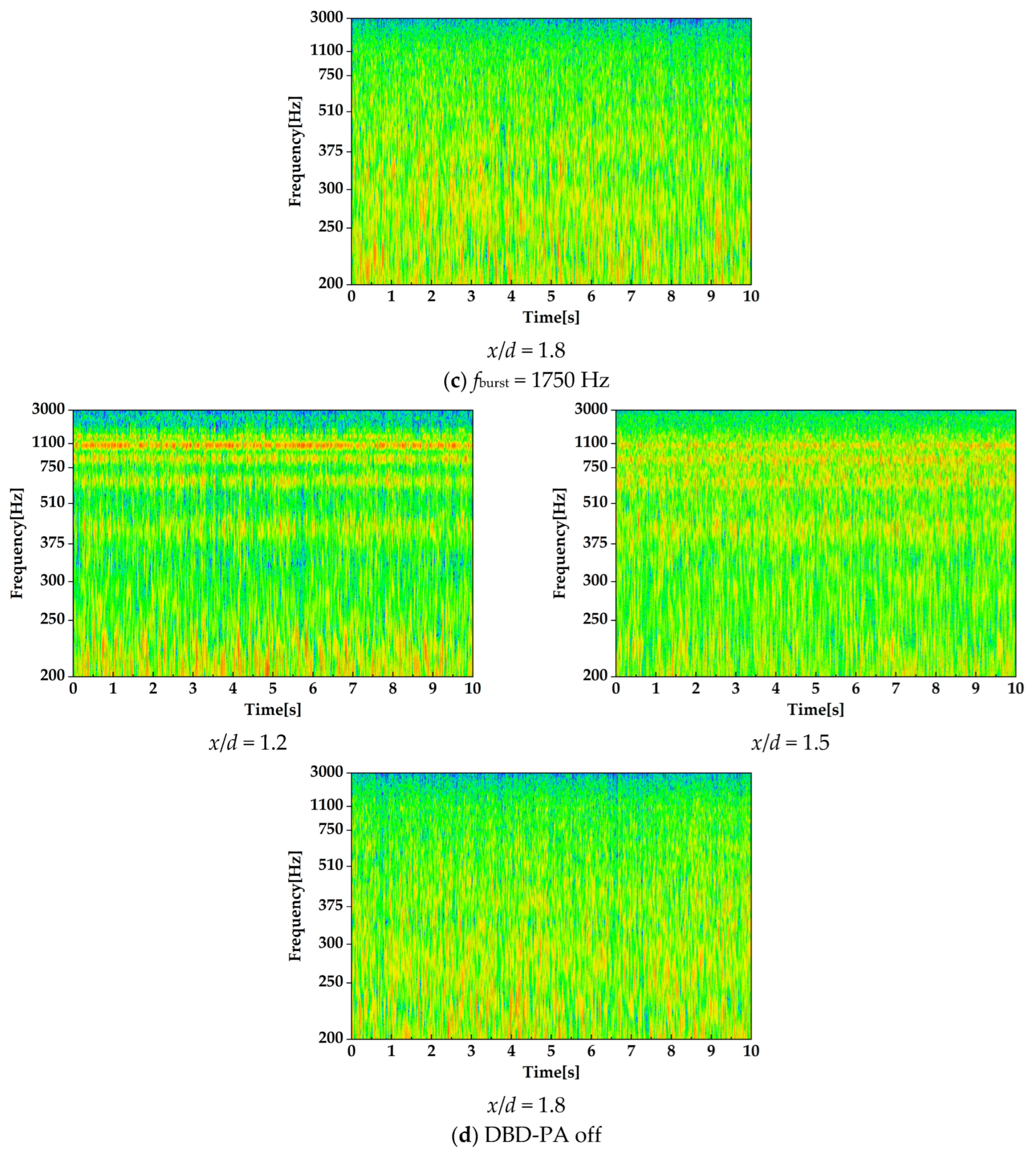
Figure 18 shows the CWT scalograms.
As shown in
Figure 18, at
x/
d = 1.2 and 1.5, the CWT intensity at
fburst = 250 and 1100 Hz was strong at the same frequency as the burst frequency. Therefore, vortices were generated under the influence of the induced flow of the DBD-PA. At
fburst = 250 Hz, the CWT intensity was also high at harmonic frequencies of 250 Hz.
At
fburst = 1100 Hz, at which the lock-in phenomenon occurred, the CWT intensity at the same frequency (1100 Hz) as the burst frequency was particularly strong. Evidently, vortices generated by the lock-in phenomenon were dominant at 1100 Hz without generating other vortices. Furthermore,
Figure 18 shows that the lock-in phenomenon occurred consistently when the DBD-PA was driven. At
x/
d = 1.8, the CWT intensity at 1100 Hz was strong, and the vortices generated by the lock-in phenomenon reached
x/
d = 1.8.
At fburst = 250 Hz, the CWT intensity at the same burst frequency was weaker than that at fburst = 1100 Hz. There were also times when the CWT intensity was strong at random frequencies other than 250 Hz, indicating that the vortices generated by the induced DBD-PA flow (250 Hz) were generated randomly. At x/d = 1.8, no specific frequency exhibited strong CWT intensity, indicating that the vortices generated at 250 Hz had collapsed.
At
x/
d = 1.2 and 1.5, the CWT intensity of the natural frequency (1098 Hz) was strong in the DBD-PA off state, and there were strong CWT intensity frequencies other than the natural frequency. Vortices and velocity fluctuations in the free jet (off) were influenced by the acoustic resonance frequencies of the jet device [
25]. Therefore, the CWT intensity was high at the acoustic resonance frequencies of the jet device. At
fburst = 1750 Hz, random periodic vortices generated by the induced flow of the DBD-PA and vortices generated by the acoustic resonance of the jet device merged upstream of the bluff body, causing vortices to occur. Therefore, the CWT results at
fburst = 1750 Hz were similar to those obtained in the DBD-PA off state. At
x/
d = 1.8, no specific frequency showed a strong CWT intensity at
fburst = 1750 Hz and DBD-PA off, indicating that the vortices had collapsed.
5.4. Comparison of Average Flow Rate and Average Velocity Distribution Downstream of the Bluff Body
This section clarifies whether differences in jet diffusion occurred at the location where recirculation was generated, depending on the driving frequency of the DBD-PA.
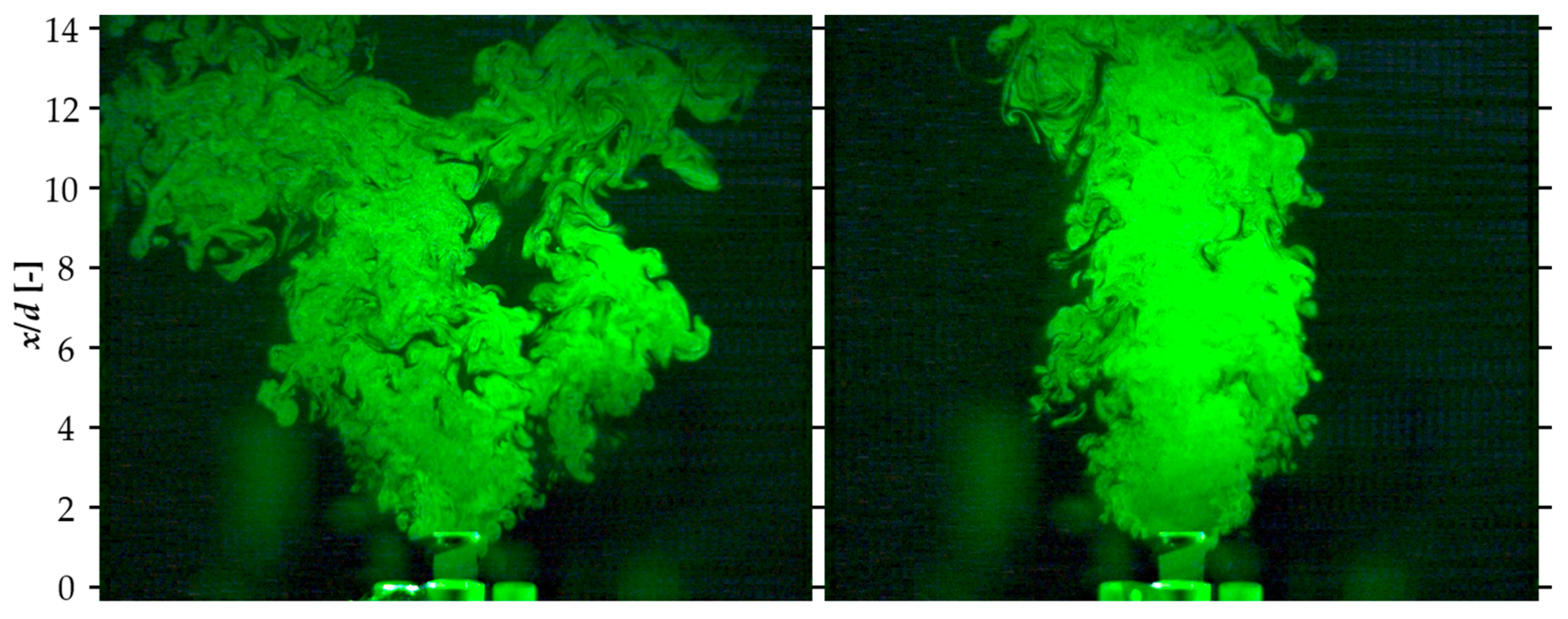
Figure 19 shows the visualization results of the jet cross-section up to
x/
d = 14 obtained by the laser light sheet method, and
Figure 20 shows the downstream average velocity distribution obtained by the PIV analysis. The visualization images indicate DBD-PA OFF,
fburst = 1100 Hz, and average velocity distributions from the PIV analysis indicate DBD-PA OFF,
fburst = 250, 1100, and 1750 Hz.
Figure 19 and
Figure 20 depict that the downstream jet width at
fburst = 1100 Hz was wider than that under other conditions. As shown in
Figure 13, at
fburst = 900–1100 Hz, the jet width was wider than under the other conditions because the vortices generated by the lock-in phenomenon were less likely to be entrained by the recirculation flow.
Next, at
x/
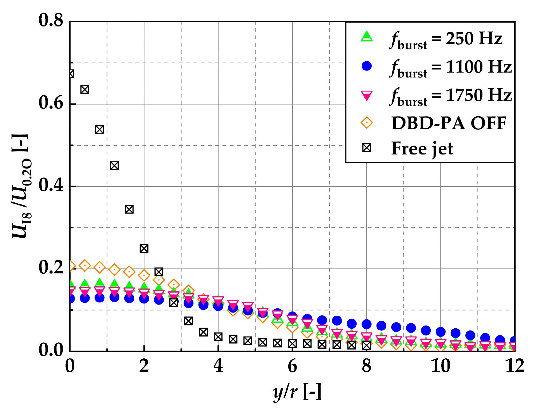
d = 8, downstream of the location where recirculation occurred, the velocity was measured in the radial direction of the nozzle using an I-type hot-wire anemometer, and the average flow rate
Qm was further calculated. The reason for using a hot-wire anemometer to determine
Qm was that it offered a higher data rate and longer measurement time compared with PIV analysis, thus ensuring higher reliability. The conditions for comparing
Qm were DBD-PA off,
fburst = 250, 1100, and 1750 Hz, and free jet. Measurements were taken using the I-type hot-wire anemometer. Because
x/
d = 8 was downstream of the recirculation, the jet advection direction was always considered to be in the positive
x-axis direction, and it was assumed that there was no measurement of the velocity in the negative
x-axis direction. The measurement points in the
y-axis direction (nozzle radial direction) were 30 points at 2 mm intervals, and the measurement positions ranged from
y/
r = 0 to 12 (0 to 0.06 m), except for the free jet, and from
y/
r = 0 to 8 (0 to 0.04 m) for the free jet. The free jet measurement point was set to
y/
r = 8 because the velocity was close to zero at
y/
r = 8. The data rate at all measurement positions was 20 kHz, and the measurement time at all measurement points was 20 s.
Qm was determined using Equation (3), where
UI8 is the average velocity at each measurement point, as measured using an I-type hot-wire anemometer:
Figure 21 shows the velocity measurement results for all conditions,
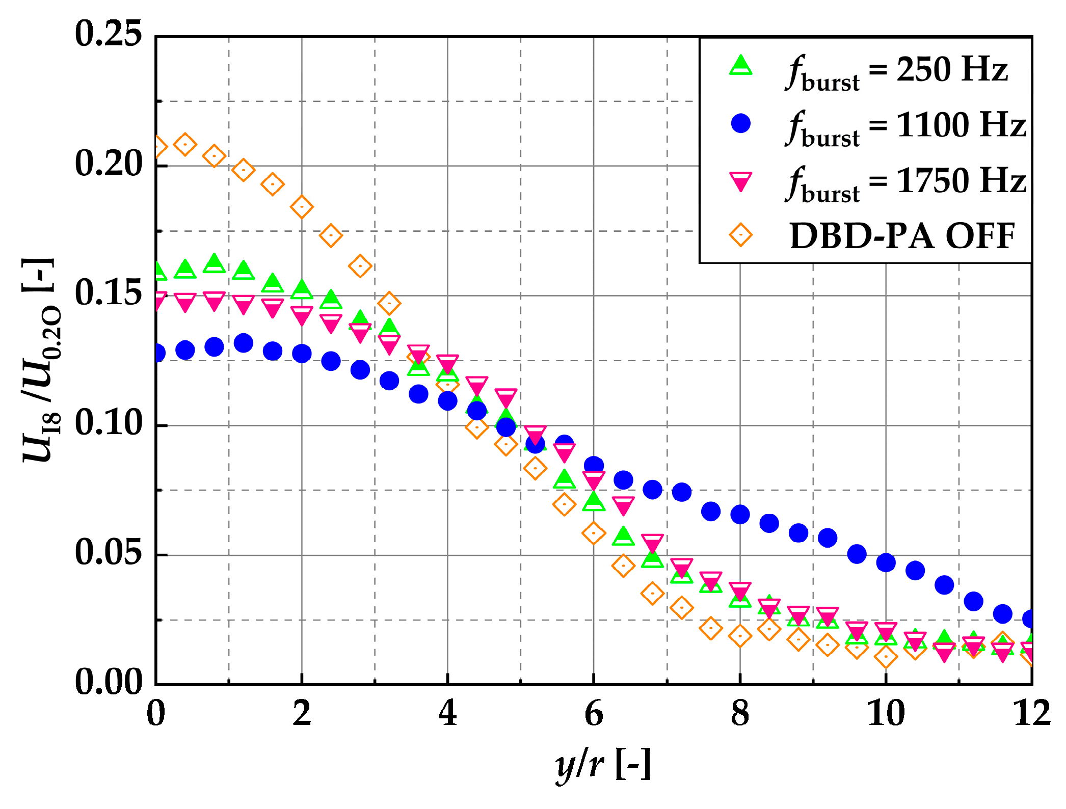
Figure 22 shows the measurement results except for the free jet, and
Table 3 compares the
Qm values. Here,
UIO is the velocity on the nozzle center axis at
x/
d = 8 with DBD-PA off, and
Qi is the initial flow rate of the jet ejected from the nozzle.
As shown in
Table 3,
Qm at
fburst = 1100 Hz and
x/
d = 8 was approximately 2.5 times larger than the free jet and approximately 1.4 times larger under than the other conditions.
Qm with the DBD-PA off and
fburst = 250 and 1750 Hz showed little difference.
The reason why Qm was larger at fburst = 1100 Hz than under other conditions was that the vortices generated at regular intervals on the outer periphery of the jet and on the recirculation side did not collapse. Therefore, vortices generated at regular intervals by the lock-in phenomenon did not coalesce and reached the downstream, expanding the jet width and thereby increasing entrainment.
