Article

Study on the Test and Adjustment Method of Civil Aircraft Taxiing Deviation

1
Shanghai Aircraft Design and Research Institute, Jinke Road No. 5188, Pudong New District, Shanghai 201210, China
2
School of Electrical Engineering and Automation, Harbin Institute of Technology, Harbin 201109, China
3
Commercial Aircraft Corporation of China, Shanghai 200126, China
*
Author to whom correspondence should be addressed.
Aerospace 2024, 11(9), 732; https://doi.org/10.3390/aerospace11090732
Submission received: 10 June 2024 / Revised: 1 September 2024 / Accepted: 5 September 2024 / Published: 6 September 2024
(This article belongs to the Special Issue Advances in Landing Systems Engineering)

Abstract

:
Civil aircrafts are highly complex systems. During the manufacturing process, deviations can occur due to cumulative errors in installation, system control, and other factors. These deviations often lead to the phenomenon of aircraft “runaway” during ground taxiing, taking off, and landing. Corrective maneuvers to address this issue not only increase the pilot’s workload but also heighten the risk of aircraft deviation from the runway. Therefore, accurately testing and aligning the side deviation angle of an aircraft is crucial for ensuring safe operations. In this paper, we first construct a mathematical model of aircraft dynamics and derive a simplified mathematical model specifically designed for aircraft trimming tests. Next, a ground taxiing trimming test is conducted to verify the accuracy of this simplified model. Additionally, we investigate the crosswind factor, which has the greatest impact on side deviation measurements, to establish the relationship between the crosswind factor and the nose wheel trimming angle. Based on this, we innovatively propose a method for achieving aircraft trimming through the equivalent trimming angle of the nose wheel. Ultimately, this approach allows aircraft trimming to be achieved with a single taxiing side deviation test, which will reduce the cost of flight tests and normal operation of the airplane when finding taxiing deviation. The method innovatively proposed in this paper offers an efficient and accurate solution for aircraft trimming tests and adjustments, significantly reducing the cost of such tests and improving the safety of civil aircraft.

1. Introduction

In the context of economic globalization, civil aviation holds a vital position within the modern comprehensive transportation system due to its unique advantages of safety, efficiency, and comfort. However, the industry faces several operational risks, including runway excursions, in-flight loss of control, controlled flight into terrain, runway incursions, and airborne collisions. Among these, runway excursions are one of the most frequent safety incidents [1]. According to the International Air Transport Association (IATA) Safety Report, runway excursions accounted for 22% of all accidents between 2010 and 2014 [2]. Similarly, data from the Aviation Safety Network (ASN) show that excursions and overruns comprised 117 out of 720 aviation accidents from 2017 to 2022, representing 16.25% of the total, making it one of the most prevalent types of accidents [3]. The frequent occurrence of runway excursion incidents has a significant impact on the operations of airlines and airports, making it a key focus of risk control and research within the civil aviation industry.
Statistics indicate that runway deviation accidents are primarily caused by factors such as unstable approaches, visual errors, insufficient piloting skills, wet or slippery runways, mechanical failures (e.g., tire blowouts, thrust reverser/decelerator malfunctions, nose wheel steering jamming), strong crosswinds, and wind shear [4,5]. However, the critical role of an aircraft’s straight-line stability in preventing runway deviations is often overlooked. Strong straight-line stability can reduce the pilot’s need for frequent corrective maneuvers during takeoff and landing, thereby decreasing the likelihood of the aircraft veering off the runway and enhancing overall safety. Therefore, accurately measuring and adjusting an aircraft’s runway deviation angle is essential for safe operations.
Huo [6] compiled a causal diagram of runway deviations using the “human-machine-environment-control” model and found that the primary factors contributing to runway deviations in Europe and elsewhere are similar to those in China. Crosswinds, slippery or contaminated runways, and directional control during taxiing were identified as the most critical factors. The countermeasures proposed in the study, focusing on airports, air traffic control, and airlines, have practical significance for preventing runway excursions.
Zhang Lei et al. [7] proposed an optimized hybrid genetic algorithm for aircraft simulators, establishing a dynamic simulation model of the aircraft and runway. By combining the strengths of genetic algorithms and pattern search, the study achieved precise ground-based aircraft trimming.
De Marco [8] investigated various trimming conditions proven effective for aircraft, deriving equations for these conditions without considering specific aircraft shapes or aerodynamic models. The study proposed a general approach to trimming through constrained minimization of a cost function based on nonlinear, six-degree-of-freedom state equations coupled with aerodynamics and propulsion models and validated the algorithm using JSBsim.
Ma [9] utilized Amesim software to build a pilot directional control model based on pre-scanning theory and PID control technology. A virtual prototype of the aircraft was constructed using LMS Virtual Lab Motion software to analyze the dynamic response under crosswind conditions. The results demonstrated effective deflection correction and control of lateral offset, verifying the feasibility of using this closed-loop control system to simulate the aircraft’s dynamic response under asymmetric loads.
Liu [10] developed a digital virtual flight-based assessment method to evaluate the ground-heading stability characteristics during crosswind landings. By focusing on key parameters such as maximum fuselage tilt angle and trajectory offset during landing taxi, the study assessed the airworthiness compliance of ground-heading maneuvering stability characteristics for a large amphibious aircraft. The proposed evaluation method can be applied during the conceptual and program design stages of civil aircraft, providing a theoretical reference for subsequent flight test verification.
Yuan Zhaohui et al. [11] explored an integrated ground directional control method using an interpolated online fuzzy control approach. By establishing nonlinear dynamic models of the rudder control system, anti-skid brake control system, and nose wheel steering control system, and combining them with fuzzy control methods, the study demonstrated that the newly designed fuzzy control method effectively eliminates steady-state errors and prevents oscillations under varying ground conditions.
He Hui et al. [12], considering flight safety, emphasized that automatic landing control laws require high accuracy and robustness. By mixing the H2/H∞ robust control method, the study designed a linear state feedback controller with pole configuration, ensuring the closed-loop control system exhibited excellent static and dynamic performance.
The above studies have utilized various control algorithms to improve the directional control characteristics of aircrafts during landing and enhance landing safety. However, there is still a lack of research and measurement on an aircraft’s straight-line stability, both domestically and internationally. Moreover, existing test methods for straight-line stability have shown insufficient accuracy in practical applications, with mainstream aircraft models’ manuals suffering from low testing accuracy and adjustment efficiency. This paper focuses on the measurement and adjustment methods for taxiing straight-line stability to address the deterioration caused by manufacturing deviations and asymmetric wear after prolonged operation, thereby improving aircraft safety.

2. Materials and Methods

2.1. Ground Dynamics Model

2.1.1. Model Assumption

This paper primarily investigates the characteristics of aircraft taxiing deviation caused by airframe imbalance. To minimize the impact of aerodynamic nonlinearities on deviation, this study focuses on the low-speed phase of taxiing. To reduce the complexity of the model, several simplifications and assumptions are made [13,14]:
  • The dual-wheel tire configuration is simplified to a single wheel.
  • The tire and landing gear structure are modeled as rigid bodies.
  • The aerodynamic effects of the elevator and aileron are neglected.
  • The impact of the engine mounting angle is disregarded.
  • The runway is assumed to be perfectly horizontal.

2.1.2. Mathematical Model

Establishing a ground dynamics data model is crucial for understanding and addressing the issue of aircraft taxiing deviation. Therefore, the mathematical model of the landing gear system dynamics is formulated as follows [15,16,17]:
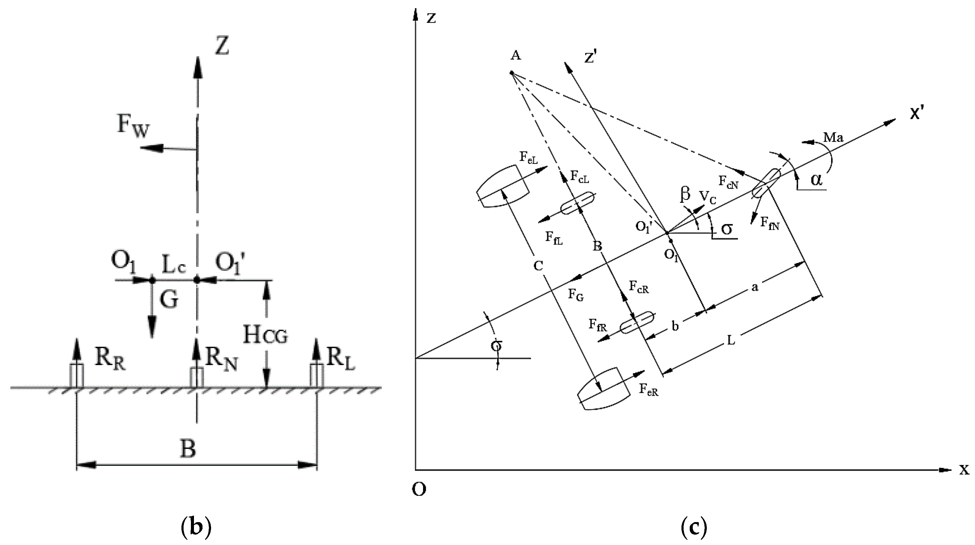
As in Figure 1a–c, if the airplane taxis along a straight line with the y-axis force balanced, then, there are F y = 0 , i.e.,
F y = F w + F f N s i n α F c N c o s α F c R F c L = 0
Since the airplane is on the ground and the airplane is balanced along the z-axis, there is F z = 0 , i.e.,
F Z = R L + R R + R N G = 0
With the airplane on the ground and the moments balanced around the OX axis, we have M x = 0 , i.e.,
M x = R L B 2 R R B 2 + G L c + F W ( H W H C G ) = 0
The aircraft is balanced along the line of moments from the left and right main wheel grounding points, then, we have M y = 0 , i.e.,
M y = F G H G G L b F e R + F e L H E + R N L = 0
Assuming that the airplane is subjected to wind from the left and the moments are balanced along the vertical line of the nose wheels, we have M z = 0 .
M z = F W L W + L a + M a + F e R F e L E 2 F c R + F c L L b F f R F f L B 2 F f N sin α F c N cos α a = 0
Additionally,
F f N = μ R N
F f R = μ R R
F f L = μ R L
F c N = μ R N
F E = F e R + F e L
The meaning of the parameters in the upper equations:
F e R : Right engine thrust;
F e L : Left engine thrust;
F E : Around total engine thrust;
F G : Aircraft drag;
F f N : Nose landing gear tire friction;
F f R : Right machine wheel tire friction;
F f L : Left side machine wheel tire friction;
α : The angle of deflection of the nose wheels of an airplane taxiing in a straight line;
F c N : Lateral forces on nose landing gear tires;
F c R : Lateral force on right landing gear tire;
F c L : Lateral force on left landing gear tire;
F w : Left crosswind forces;
R N : Nose rise branch reaction force;
R R : The right main starting branch counterforce;
R L : The left main starts the branch counterforce;
G : Aircraft gravity;
B : Left and right main wheelbase;
L c : Actual center of gravity versus distance from the center of the body;
H W : Mean crosswind force height from the ground;
H C G : Height of the center of gravity from the ground;
H G : Average resistance height from the ground;
L a : The distance of the nose start grounding point from the center of gravity O in the x-axis direction;
L b : The distance of the main start grounding point from the center of gravity O in the X-axis direction;
L : Nose main wheelbase;
H E : Engine height from the ground;
L W : Distance of the mean crosswind force from the center of gravity of the aircraft;
M a : Aerodynamic moment induced asymmetric moment of rotation about the oz axis;
C : Distance between left and right engine centers;
μ : Coefficient of friction between tire and ground;
μ : Coefficient of friction of nose tires in lateral direction against the ground.
The airplane glides in a straight line; the nose wheel of the airplane is corrected at a small angle, and α tends to 0°, so cos α 1 , sin α α , and F c R , F c L 0 . Then, jointly with the above formulas, we can obtain the deflection angle α of the nose wheel required to maintain a straight-line glide of the airplane in the case of airframe imbalance and crosswind as follows:
α = L { [ F W L W + L a + M a + F e R F e L E 2 μ [ G L c + F W ( H W H C G ) ] } / { G L b + F e R + F e L H E F G H G μ a } + μ / μ
From the above Equation (11), it can be seen that in the case of a certain crosswind F W , the decreased trimming angle α of the nose wheel can be obtained as follows:
  • Reducing the unbalance aerodynamic moment M a : this can be achieved by adjusting the horizontal degree of the left and right wings and the horizontal tail, as well as the vertical tail;
  • Reducing the asymmetry of the aircraft thrust F f R and F c L : this can be achieved by adjusting the consistency of the left and right engine speeds under the same engine thrust command;
  • Reducing L c : achieved by adjusting the longitudinal balance of fuel and cargo, etc.;
  • Increasing the coefficient of friction μ : by changing the tire with new one to increase the friction.
It should be clear that, even though the above factors are adjusted within the targets’ range, the aircraft may still find taxiing deviation; for example, the taxiing deviation was often found during the production taxiing test, and all factors mentioned above are within limitation.
In order to better carry out the study, the above factors can be simplified by dividing them into the internal factors and external factors of the airplane, and the rewriting of the above equation in terms of the internal and external factors can be expressed as follows:
α = f ( a ) + f ( b ) s t d
f ( a ) : It is an external influencing factor for aircraft taxiing deviation, mainly caused by crosswind;
f ( b ) s t d : For the factors influencing aircraft taxiing deviation ontology, including engine thrust asymmetry, drag asymmetry, center of gravity asymmetry, etc., in the above.
In case the airplane is subjected to wind from the right side, the same reasoning can be applied that the required trimming angle α of the airplane is as follows:
α = L { [ F W L W + L a + M a + F e R F e L E 2 μ [ G L c F W ( H W H C G ) ] } / { G L b + F e R + F e L H E F G H G μ a } + μ / μ = f ( a ) + f ( b ) s t d
Eliminating the amount of aircraft deviation f ( a ) due to crosswinds yields the aircraft deviation angle f ( b ) s t d due to the aircraft body factors as follows:
f ( b ) s t d = ( α + α ) / 2
The above equation shows that the nose wheel deflection angle f ( a ) caused by the crosswind factor can be eliminated by forward and reverse taxiing (changing the direction of the crosswind), and the side deviation angle f ( b ) s t d caused by the body of the airplane can be obtained by averaging the nose wheel deflection angle α and α , the average of the nose wheel deflection angle of the airplane that keeps the airplane in a straight line during the forward and reverse taxiing processes.

2.2. Aircraft Trimming Test Method

2.2.1. Test Fundamentals

Based on operational experience, pilots can detect an aircraft’s deviation during straight-line taxiing when the nose wheel is deflected by 0.3° to 0.5°. To accurately determine the equivalent nose wheel trimming angle, a measurement precision of 0.1° is required. However, it is highly challenging for pilots to maintain a stable adjustment of approximately 0.1° using the steering handwheel or rudder pedals, making it impractical to measure the equivalent nose wheel angle through manual manipulation.
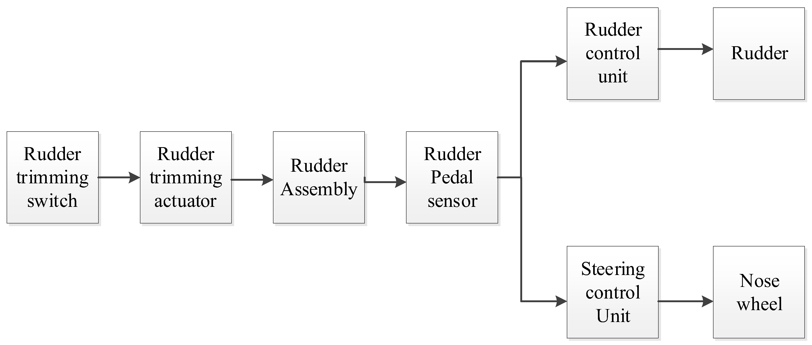
Modern civil airliners are typically equipped with rudder trimming switches to compensate for crosswinds or airframe imbalance. These switches adjust the position of the rudder trimming actuator, which, in turn, alters the positions of the pedal assemblies and pedal position sensors, thereby reducing the pilot’s workload in cases of aircraft imbalance. As illustrated in Figure 2 below, the rudder trimming switch adjusts the stabilized position of the rudder pedal assembly, changing the zero angle of the angle sensor. Since the rudder pedal sensors control both the rudder and the nose wheels, any adjustments made via the rudder trimming switch will cause the nose wheels to deflect accordingly.
The rudder trimming switch can achieve an adjustment accuracy of 0.1°, with the adjustment amount displayed in the cockpit, making it feasible to trim the aircraft’s nose wheel using this switch and determine the equivalent nose wheel tilt angle. According to the system design, the output of the rudder trimming switch is directly proportional to the pedal sensor output, the rudder trimming actuator position, and the nose wheel turn. This establishes a positive proportional relationship between the rudder trimming switch adjustment and the nose wheel steering angle, which can be described as follows:
α = k x
x : Rudder trimming switch trimming volume;
k : Coefficient of proportionality between rudder trimming and nose wheel angle (for a certain type of aircraft, take 0.4);
α : Nose wheel trimming angle;

2.2.2. Test Procedure

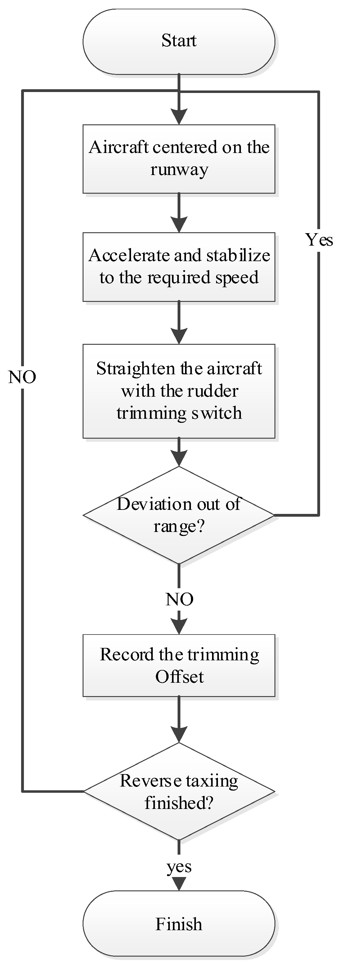
In order to determine the correctness of the previous assumptions about external factors, the verification test process as showed in Figure 3 is carried out according to the following test procedure:
  • First, taxi the aircraft to the centerline of the runway using the nose wheel steering function, ensuring that the nose of the aircraft is aligned with the runway centerline. This step can prevent any impact on test accuracy due to the “turtle-back” structure of the runway, which is higher in the middle and lower on the sides.
  • Once the aircraft is aligned with the runway, adjust its speed using the throttle lever. The speed should be moderate, because it should be high enough to conduct the test effectively but low enough to minimize the risk of runway deviation and reduce the influence of aerodynamic forces on the test.
  • Use the rudder trimming switch to adjust the trimming angle X1, so that the aircraft maintains straight-line taxiing.
  • Observe whether the aircraft’s lateral deviation exceeds the standard, typically requiring that the deviation be no more than 4.5 m over 10 s. If the deviation exceeds this standard, the trimming test must be repeated.
  • If the deviation is within the acceptable range, record the rudder trimming amount X1.
  • Turn the aircraft around, perform reverse taxiing with same period runway as step (1) to step (5), and record the trimming angle X2.
By conducting both forward and reverse taxiing tests on the same runway section, the impact of runway unevenness can be effectively reduced during test.

3. Results

3.1. Test Sample and Result

Based on the test procedure outlined above, the aircraft was subjected to a positive easterly wind with a maximum wind speed of 3 m/s and a taxiing speed of 15 knots. The rudder trimming switch was used to control the direction and correct the deflection, ensuring that the aircraft maintained straight-line taxiing for 10 s with a deviation of no more than 4.5 m from the runway centerline.
The test results indicated that the rudder trimming amount was X1 = −1.3° for taxiing from south to north (defined as forward taxiing) and X2 = −2.8° for taxiing from north to south (also defined as forward taxiing).
Note: A positive angle indicates trimming to the left, while a negative angle indicates trimming to the right.
Using these values in the corresponding equations, the equivalent nose wheel deflection angle required to trim this aircraft is as follows:
f ( b ) s t d = ( α + α ) / 2 = ( k x 1 + k x 2 ) / 2 = 0.4 ( 1.3 ° 2.8 ° ) / 2 = 0.8 °
In other words, the aircraft needs to be trimmed 0.8° to the right using the nose wheel steering system to achieve straight-line taxiing.
Additionally, based on the test data, if there are no crosswind or runway effects, the measured trimming amounts X1 and X2 should be identical for both forward and reverse taxiing. However, the significant deviation between X1 and X2 observed in the test corresponds to a nose wheel deflection angle of
Δ α = k | X 1 X 2 | / 2 = 0.4 × | 1.3 ° + 2.8 ° | / 2 = 0.3 °
The equivalent side deflection angle under a 3 m/s crosswind is 0.3°.
To further validate the test method, different nose wheel deflection angles (within the range of ±1°) were preset to maintain the aircraft in various lateral deflection states (with an initial required trimming angle of 0.8°). Regression tests were conducted under a 3 m/s crosswind, and the results are shown in Table 1.
According to the test data, the error between the theoretical and measured trimming angles is within 0.2° across different preset angles, demonstrating high trimming test accuracy that meets the 0.3° threshold recognizable by the pilot.
Under different trimming angles, the equivalent crosswind deflection angle ranges from 0.2° to 0.3°. The method of forward and reverse taxiing effectively attenuates the side deflection caused by crosswind and runway conditions, achieving a trimming test accuracy within 0.2°.
According to the test data above, under different preset angles (show in Figure 4, black line with square), the error between the theoretical trimming angle and the measured trimming angle is within 0.2° (show in Figure 4, green line with inverted triangle), and the trimming test accuracy is high and meets the requirement of 0.3° recognizable by the pilot.
Under various trimming angles, the equivalent crosswind deflection angle ranges from 0.2° to 0.3°. By employing forward and reverse taxiing methods, the side deflection caused by crosswinds and runway conditions is effectively mitigated, achieving a trimming test accuracy within 0.2°.

3.2. Analysis of the Impact of Crosswind

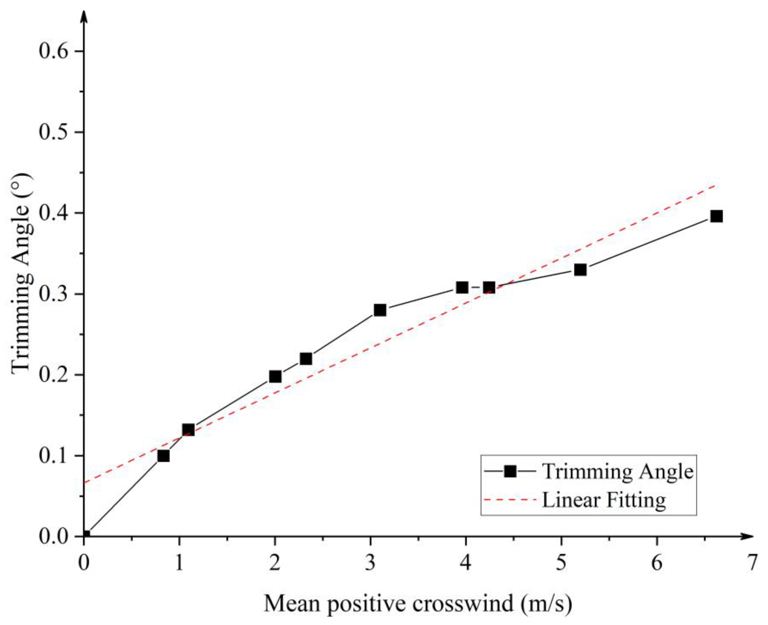
Using the same trimming method, tests were performed on 10 different aircrafts of this type under varying crosswind conditions. The relationship between the obtained trimming angle and the mean positive crosswind value is illustrated in Figure 5. The results show that as the positive crosswind increases, the required trimming angle also increases proportionally.
Based on the experimental results above, the relationship between the crosswind and trimming angle can be obtained by linear fitting as follows:
f ( a ) = k 2 f c sin θ + d
k 2 : relationship coefficients between the crosswind and the trimming angle (for this type of aircraft, k 2 is 0.05);
f c : the value of crosswind, m/s;
θ : angle between the direction of the crosswind and the longitudinal plane of the aircraft;
d : the offset between the theoretical trimming angle and the actual trimming angle under the crosswind (for this type of aircraft, d is 0.08);
Based on the analyses above, the relationship between trimming angle α , crosswind fc, and rudder pedal trimming value x can be described as follows:
α = f ( b ) s t d ± f ( a ) = k 1 x ± ( k 2 f c + b ) = 0 . 4 x ± ( 0 . 05 f c sin θ + 0 . 08 )
According to the equation above, based on the rudder trimming measurement value during taxiing test and the measured crosswind value and angle at the airport during the test, the required nose wheel trimming angle of the aircraft can be calculated, and this method can reduce one reverse taxiing and improve the efficiency of aircraft trimming test.

3.3. Aircraft Trimming Adjustment Methods

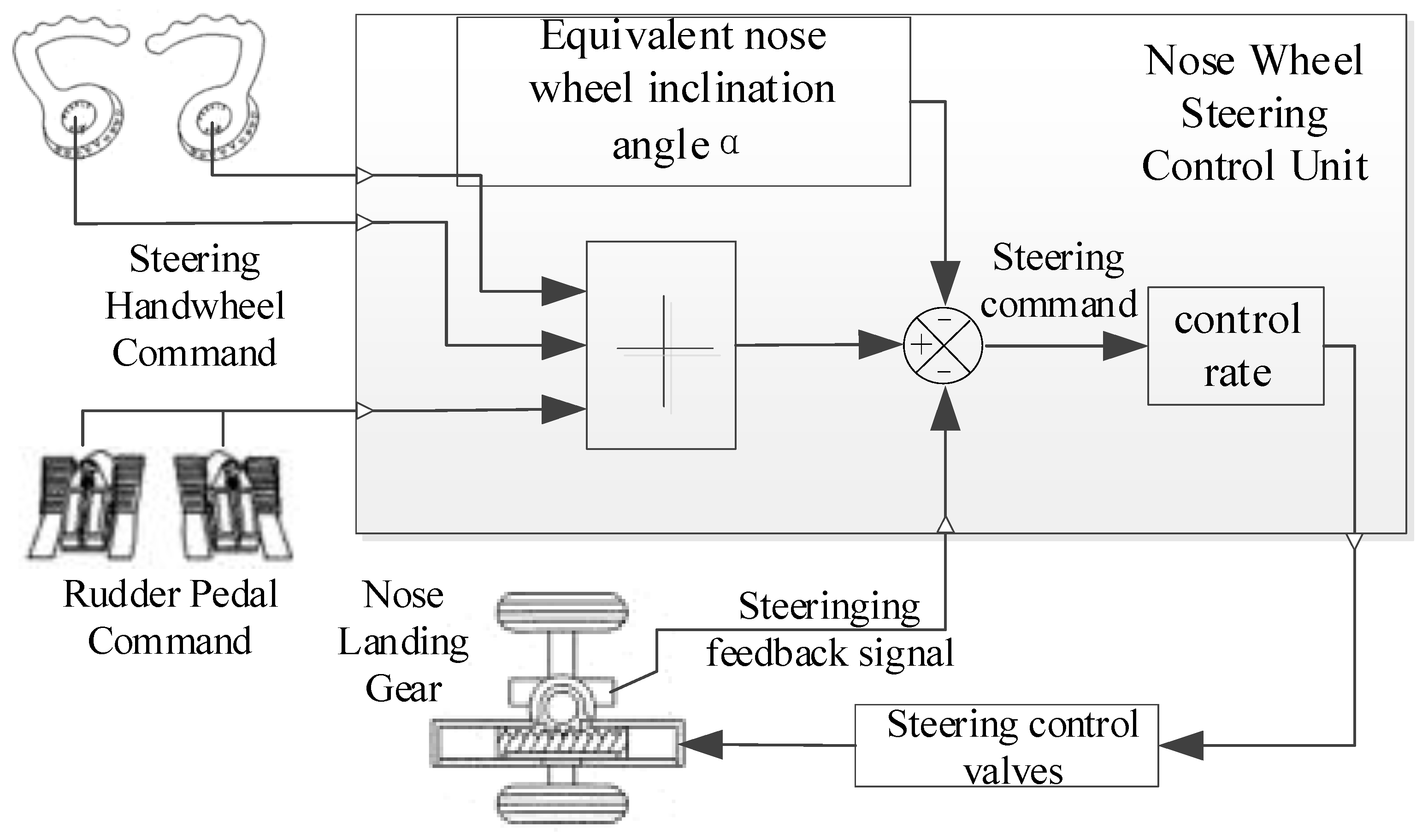
In order to make the airplane have a nose wheel trimming angle at the initial state, the deflection correction can be carried out by reversing the superimposition of the equivalent nose wheel inclination angle in the nose wheel steering control unit, and the realization process is shown in following Figure 6:
As depicted in Figure 6 above, the schematic diagram illustrates a nose wheel steering closed-loop control system designed for equivalent nose wheel camber correction. The system integrates the steering handwheel and rudder pedal commands as input signals. These inputs, along with feedback from the nose wheel steering angle sensor and the equivalent nose wheel tilt angle, are processed by the control algorithm.
The nose wheel steering control unit calculates the necessary control signal, which is sent to the nose wheel steering control valve to regulate the movement of the nose steering actuator. This adjustment aligns the nose wheel steering accordingly.
When both the steering handwheel and rudder pedal are at zero, the control unit outputs a steering command α. This command magnitude is equivalent to the airplane’s nose wheel tilt angle but in the opposite direction. This adjustment ensures that the nose wheel compensates by turning in the opposite direction of the tilt, thereby counteracting the deviation and enabling the aircraft to maintain straight-line taxiing.

4. Discussion

Comparing with the reference literature [7,8,9,10,11,12], we share the same aim of reducing the risk of aircraft veering off the runway; however, our ways of achieving this differ greatly. Reference [6] developed a causal diagram of the aircraft runway excursion problem and drew the conclusion that crosswinds, runway, and maneuver control are the most important factors in runway excursions, which provided guidance for this paper to focus on crosswinds and runway factors in this study; Reference [10] developed a digital virtual flight-based evaluation method to achieve the evaluation of the ground-heading stability characteristics during landing in crosswind, and the evaluation of the key parameters of trajectory deviation of this research species provided ideas for the experimental setup of this paper. In addition, Reference [7] achieved the trimming of the simulator by a hybrid genetic algorithm; Reference [8] used the cost function constraint minimization trimming method to achieve a general trimming method under various environmental conditions, and Reference [9] achieved the virtual inspection machine trimming control based on the pre-aiming theory and PID control technology method. Reference [11] used the interpolation online fuzzy control method to achieve the aircraft-integrated ground direction control; Reference [12] used hybrid H2/H∞ robust control method to achieve a high precision and high robustness of aircraft control. The above literature [7,8,9,11,12] expect to achieve straight-line taxiing of aircraft under various disturbing conditions through control algorithms to avoid aircraft deviation from the runway, while this paper achieves it by studying the internal and external influences on the side deviation of the aircraft and, through the theoretical derivation and taxiing tests to achieve the measurement of the side deviation of the aircraft body, finally realizes the aircraft body trimming.
In conclusion, this study set out to find a new method for accurately and rapidly testing and adjusting aircrafts with taxiing deviation. In order to achieve the target, this paper first established the relationship between an aircraft’s taxiing deviation and its internal and external factors using a ground dynamics model. It derived a theoretical calculation formula to eliminate the crosswind factor through forward and reverse taxiing and determined the relationship between the required trimming angle and the nose wheel deflection angle.
The validity and accuracy of the trimming method using rudder pedals were tested and verified by presetting different nose wheel deflection angles. Additionally, by analyzing the equivalent trimming values caused by crosswinds across various aircraft of the same type and correlating these with crosswind data, a relationship equation between crosswind and aircraft trimming value was fitted. This further simplified the rudder trimming measurement method, allowing the aircraft trimming test to be completed in a single taxiing session.
Finally, a method for rapidly achieving aircraft trimming adjustment was proposed by incorporating a trimming offset into the nose wheel steering control unit.
Although this paper innovatively proposes a method for aircraft trimming testing and adjustment through theoretical derivation and comparative tests, due to the limitations of time, energy, and resources, this paper still has constraints, i.e., this paper only gives the relationship between the aircraft trimming angle and the mean positive crosswind at common rates and does not further explore the relationship at higher speeds, which may pose constraints during aircraft trimming tests in harsh crosswind environments.

5. Conclusions

This paper begins by constructing a mathematical model of aircraft dynamics and innovatively deriving a simplified model applicable to aircraft trimming tests. A ground taxiing trimming test is then designed to verify the accuracy of this simplified model. Further experimental research investigates the crosswind factor, which significantly affects side deviation measurements. This research establishes the relationship between the crosswind factor and the nose wheel trimming angle and proposes a method for achieving aircraft trimming through the equivalent nose wheel trimming angle. Consequently, this approach allows aircraft trimming to be completed with a single taxiing side deviation test.
In conclusion, the method proposed provides an efficient and accurate solution for aircraft trimming tests and adjustments, effectively reducing the cost of civil aircraft trimming and adjustment processes while enhancing safety. Through both theoretical derivation and experimental verification, this paper offers a comprehensive test and trimming adjustment method for aircraft taxiing side deviation, providing valuable insights for addressing engineering challenges related to aircraft taxiing side deviation and demonstrating significant engineering application potential.

Author Contributions

Conceptualization, W.C. and Y.C.; methodology, W.C.; software, Y.X.; validation, W.C., Y.C. and Y.X.; formal analysis, W.C.; investigation, W.C.; resources, Y.C.; data curation, Y.X.; writing—original draft preparation, W.C.; writing—review and editing, W.C.; visualization, Y.C.; supervision, Y.C.; project administration, Y.J.; funding acquisition, Y.X. All authors have read and agreed to the published version of the manuscript.

Funding

This research received no external funding.

Data Availability Statement

From privacy reasons, it is not possible to disclose additional data.

Conflicts of Interest

Author Yong Chen was employed by the company Commercial Aircraft Corporation of China The remaining authors declare that the research was conducted in the absence of any commercial or financial relationships that could be construed as a potential conflict of interest.

References

  1. Vorobyeva, O.; Bartok, J.; Šišan, P.; Nechaj, P.; Gera, M.; Kelemen, M.; Polishchuk, V.; Gaál, L. Assessing the contribution of data mining methods to avoid aircraft run-off from the runway to increase the safety and reduce the negative environmental impacts. Int. J. Environ. Res. Public Health 2020, 17, 796. [Google Scholar] [CrossRef] [PubMed]
  2. IATA. Runway Safety Accident Analysis Report 2010–2014, 1st ed.; IATA: Montreal, QC, Canada, 2015. [Google Scholar]
  3. Available online: https://aviation-safety.net/database[DB/OL] (accessed on 1 May 2024).
  4. Huo, Z.-Q.; Ru, Y.; Han, S.-C. A model for analyzing runway deviation events during the landing phase of civil aviation transportation aircraft. J. Southwest Jiaotong Univ. 2012, 47, 895–900. [Google Scholar]
  5. Wang, F.; Yuan, J.; Liu, X.; Wang, P.; Xu, M.; Li, X.; Li, H. Impacts of Flight Operations on the Risk of Runway Excursions. Appl. Sci. 2024, 14, 975. [Google Scholar] [CrossRef]
  6. Huo, Z. Research on the cause analysis and prevention strategy of runway deviation of civil aviation transportation aircraft. In Management Science and Engineering (MSE 2011 V6); Information Engineering Research Institute: Chengdu, China, 2011; pp. 247–252. [Google Scholar]
  7. Zhang, L.; Huang, Q.; Jiang, H.; Han, J. Trimming aircraft on the ground based on the hybrid genetic algorithm. Trans. Jpn. Soc. Aeronaut. Space Sci. 2009, 52, 117–124. [Google Scholar]
  8. De Marco, A.; Duke, E.; Berndt, J. A general solution to the aircraft trim problem. In Proceedings of the AIAA Modeling and Simulation Technologies Conference and Exhibit, Hilton Head, SC, USA, 20–23 August 2007; p. 6703. [Google Scholar]
  9. Ma, D.; Nie, H.; Zhang, M. Study of deflection correction of civil aircraft under the influence of crosswind. Flight Mech. 2013, 31, 23. [Google Scholar]
  10. Liu, H.; Wang, L. Evaluation of ground heading maneuvering stability characteristics of civil aircraft landing in crosswind based on digital virtual flight. J. Beijing Univ. Aeronaut. Astronaut. 2018, 44, 516–525. [Google Scholar]
  11. Yuan, Z.; Wang, Y. A design of airplane’s integrated ground directional system with fuzzy control. In Proceedings of the 2009 Sixth International Conference on Fuzzy Systems and Knowledge Discovery, Tianjin, China, 14–16 August 2009. [Google Scholar]
  12. He, H. Research on Longitudinal Control Technology for Automatic Landing of Unmanned Aircraft; Nanjing University of Science and Technology: Nanjing, China, 2008. [Google Scholar]
  13. Zhang, M. Research on Some Key Technologies of Aircraft Ground Dynamics; Nanjing University of Aeronautics and Astronautics: Nanjing, China, 2009. [Google Scholar]
  14. Zhao, Z.; Wang, H.; Li, L.; Jiang, Y. A study of ground maneuver stability of multiple-bogie undercarriage. In Proceedings of the 2016 IEEE International Conference on Aircraft Utility Systems (AUS), Beijing, China, 10–12 October 2016; pp. 362–366. [Google Scholar]
  15. Zhou, J. Research on the calculation method of nose wheel steering deviation angle of a certain type of civil aircraft. Sci. Technol. View 2018, 29, 21–22. [Google Scholar]
  16. Duprez, J.; Mora-Camino, F.; Villaumé, F. Aircraft-on-Ground Lateral Control for Low Speed Maneuvers. Ifac Proc. Vol. 2004, 37, 475–480. [Google Scholar] [CrossRef]
  17. Aircraft Design Manual: Volume 14, Takeoff and Landing System Design; Aviation Industry Press: Beijing, China, 2002; pp. 38–79.
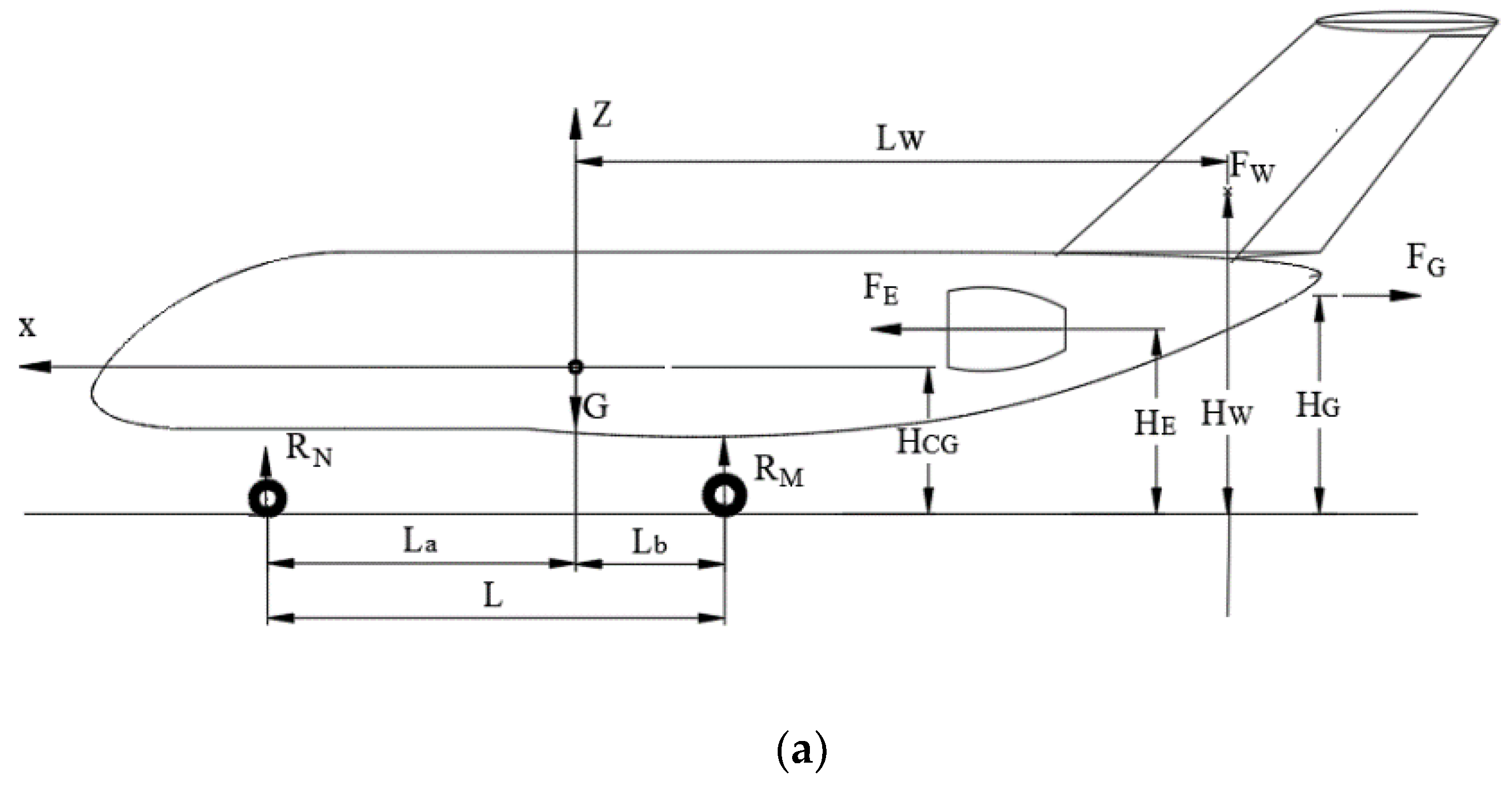
Figure 1. Analysis of aircraft forces on ground. (a) Lateral force analysis diagram; (b) Forward force analysis diagram; (c) Overhead force analysis diagram.
Aerospace 11 00732 g001aAerospace 11 00732 g001b
Figure 2. The rudder trimming switch and the relationship between the rudder and the action of the nose wheel.
Aerospace 11 00732 g002
Figure 3. Trimming test process.
Aerospace 11 00732 g003
Figure 4. Regression trimming test.
Aerospace 11 00732 g004
Figure 5. Analysis of the effect of crosswinds on the lateral deviation of airplane taxiing.
Aerospace 11 00732 g005
Figure 6. Steering system trimming adjustment method.
Aerospace 11 00732 g006
Table 1. Table of regression test results.
Test PointNose Wheel Presetting Deflection Angle (°)Measured Value of Trimming Quantity X1 (°)Measured Value of Trimming Quantity X2 (°)Theoretical Trimming Angle (°)Measured Trimming Angle (°)Theoretical and Actual Error (°)Crosswind Equivalent Deflection Angle Δα (°)
1−10.9−0.40.20.10.10.3
2−0.70.2−0.8−0.1−0.10.00.2
3−0.3−1−2.2−0.5−0.70.20.3
40.1−1.6−2.6−0.9−0.90.00.2
50.5−2.7−3.7−1.3−1.40.10.2
61−3.7−4.9−1.8−1.90.10.3
Disclaimer/Publisher’s Note: The statements, opinions and data contained in all publications are solely those of the individual author(s) and contributor(s) and not of MDPI and/or the editor(s). MDPI and/or the editor(s) disclaim responsibility for any injury to people or property resulting from any ideas, methods, instructions or products referred to in the content.