Article

Direct Closed-Loop Control Structure for the Three-Axis Satcom-on-the-Move Antenna

1
School of Power and Energy, Northwestern Polytechnical University, Xi’an 710072, China
2
Satpro M&C Tech Co., Ltd., Xi’an 710018, China
*
Author to whom correspondence should be addressed.
Aerospace 2024, 11(8), 659; https://doi.org/10.3390/aerospace11080659
Submission received: 23 June 2024 / Revised: 30 July 2024 / Accepted: 8 August 2024 / Published: 12 August 2024

Abstract

:
The traditional Satcom-on-the-Move (SOTM) mechanical structure consists of a dual-axis configuration with an azimuth axis and a pitch axis. In this structure, when the pitch angle is 90 degrees, the rotation of the azimuth axis cannot change the antenna’s direction. To solve this issue, a three-axis SOTM mechanical structure has been developed. The traditional three-axis SOTM servo control system adopts a closed-loop control scheme. In this scheme, due to the difficulty in directly obtaining the antenna’s rotation angle, the angles of rotation for each axis are typically selected to represent the antenna’s rotation angle. The closed-loop feedback includes the angles and angular velocities of the axes, which cannot completely capture the antenna’s motion state, essentially constituting an indirect closed-loop control. Addressing the shortcomings of this indirect closed-loop control, this paper first establishes the kinematic relations between the axes of the three-axis SOTM antenna using the Denavit–Hartenberg (DH) method. Subsequently, the relationship between antenna pointing and the rotational states of the three axes was derived using the Jacobian operator. Building upon this foundation, a direct closed-loop control structure for a three-axis SOTM antenna was designed. To enable the control system to achieve rapid convergence with minimal overshoot, an Active Disturbance Rejection Control (ADRC) algorithm based on smooth continuous functions is introduced as the inner and outer loop controller algorithms within the direct closed-loop control structure. To address the nonlinearity in the design scheme, a piecewise linearization method is proposed to reduce the demands on the microprocessor’s performance and enhance the engineering feasibility of the solution. Finally, the effectiveness of the proposed approach is validated through experiments. The experimental results demonstrate that compared to traditional indirect closed-loop control methods, utilizing the direct closed-loop control method for the three-axis SOTM antenna presented in this paper can lead to higher precision in pointing the antenna towards satellites and enhance communication effectiveness.

1. Introduction

The Internet plays an increasingly important role in people’s daily lives [1,2,3], especially with the development of wireless communication technologies, allowing for terminal devices to break free from the constraint of wired connections, greatly expanding the application scope and scenarios of the Internet. Currently, wireless Internet communication relies primarily on base stations provided by Internet Service Providers (ISPs). With the passage of time, the number of base stations has rapidly increased, covering not only urban areas but also extending to rural regions and the wilderness, further expanding the range and scenarios where wireless Internet services can be used. However, due to factors such as technology, cost, and security, ISP base stations struggle to provide coverage over the entire globe, and there are still numerous ISP base station blind spots on Earth [4,5], such as in areas like primary forests, deserts, and high seas. Although these regions typically lack significant human activity, there are specific situations that necessitate Internet services, such as forest fire prevention, television broadcasts for sports events like car rallies, Internet services on cruise ships, and high seas rescue [6]. As a result, relying solely on wireless Internet communication through ISP base stations proves insufficient to meet the diverse demands for Internet usage [7,8].
Satellite communication uses communication satellites in space as relays to achieve communication between terminal equipment and satellite ground stations. It is an important supplement to the Internet communication mode based on ISP base stations [9,10]. Satellite communication has advantages such as wide coverage, fewer restrictions from ground infrastructure, and simple and quick deployment. Satcom-on-the-Move (SOTM) is a technology for satellite communication during carrier motion processes. Due to its avoidance of the limitations on carrier operational status in conventional satellite communication, it has received widespread attention and has been widely applied [11].
During the movement of the carrier, its location and attitude generally undergo dynamic changes. To establish communication with the satellite, the SOTM antenna needs to adjust its azimuth and pitch angles in real-time, thereby aligning the antenna beam with the target communication satellite. Additionally, in order to achieve stable and efficient communication, it is required that the SOTM antenna beam pointing has a high degree of accuracy. For example, the FCC mandates that the angle between the antenna beam and the satellite must not exceed 0.2 ° [12]. When the angle between the antenna beam and the satellite exceeds 0.2 ° , the ability to send and receive signals between the antenna and the satellite rapidly decreases, leading to an increase in packet loss rates, potentially affecting communication effectiveness, and it may also cause communication interference with neighboring satellites. As the angle between the antenna beam and the satellite continues to increase, it may result in communication interruptions [13]. Higher pointing accuracy enhances satellite communication reliability and, for the same network speed requirements, can reduce satellite bandwidth leasing costs, thereby lowering the operational and usage costs of SOTM Internet services [14].
The mechanical design of the SOTM antenna can meet the operating requirements in most conditions by using an azimuth-pitch dual-axis structure. By relying solely on these two axes, it can cover a sufficiently large Spherical Cap. When the pitch is within [0,90°], it can even cover the entire hemisphere. This design offers advantages such as a small size, low weight, a simple structure, and good robustness [15]. However, for this type of mechanical structure, when the pitch angle is 90 degrees, the antenna’s pointing direction no longer changes with the rotation of the azimuth axis [16]. To address this issue, by adding a roll axis in addition to the azimuth and pitch axes, the SOTM mechanical structure becomes a three-axis configuration [17].
For SOTM systems, the antenna beam’s deviation angle from the target satellite must be kept sufficiently small while the carrier is in motion. Therefore, the SOTM system requires a sufficiently high servo control accuracy [18]. Currently, most SOTM servo control systems are designed using a PID control. It has the advantages of a simple structure, easy software coding, extensive engineering experience, and convenient parameter tuning. However, a PID control finds it challenging to achieve both fast system response and sufficiently low overshoot simultaneously. Consequently, when the carrier’s attitude changes or its position moves, it becomes difficult for the antenna beam to adjust quickly and accurately to the target angle [19,20]. Additionally, the normal operation of SOTM also requires that the carrier’s attitude measurement system has a very high measurement accuracy [21]. Therefore, conventional Micro-Electro-Mechanical Systems (MEMS) inertial devices, such as MEMS gyroscopes, struggle to meet the operational requirements of SOTM systems in terms of accuracy. In practical applications, high-precision gyroscopes like fiber optic gyroscopes are often used, but these high-precision Inertial Measurement Units (IMUs) are typically heavy and bulky, making it difficult to install them in areas like the antenna face. They are usually fixedly connected to the carrier instead [22]. While this design enhances the measurement accuracy of the carrier’s location and attitude, it is challenging to directly obtain pointing information for the antenna terminal beam. Typically, the pointing of the antenna terminal beam is indirectly represented through measuring the motion states of each drive axis with encoders and other means. Hence, conventional SOTM closed-loop servo control systems are mostly indirect closed-loop controls rather than direct closed-loop controls.
The contribution of this paper lies in obtaining the kinematic relationships among the three axes of SOTM based on the new modified DH (NMDH) method for the SOTM structure and providing a linear approximation method that is convenient for engineering implementation. Based on the Jacobian operators in robotics [23,24,25] to synthesize the kinematic relationships between each axis, the relationship between the antenna beam pointing and the carrier attitude is obtained, thereby achieving the direct closed-loop control of the antenna beam. Introducing an ADRC control algorithm based on the smooth continuous f a l function, it can overcome the contradiction between speed and overshoot in a traditional PID control, thereby improving the quality of SOTM servo control.
The organization of the remaining sections of this paper is as follows: Section 2 introduces a three-axis SOTM mechanical structure and presents an NMDH method to derive the kinematic relationships among the rotational axes of the three-axis SOTM; Section 3 designs a direct closed-loop control structure based on the Jacobian operator; and Section 4 introduces a new ADRC, in which the f a l function is smooth and continuous. This ADRC is used as both the inner and outer loop controller of the system. Section 5 focuses on experimental verification, primarily validating the proposed schemes through experiments; Section 6 summarizes the entire contents of the paper.

2. The Kinematic Relationship of the Three-Axis SOTM

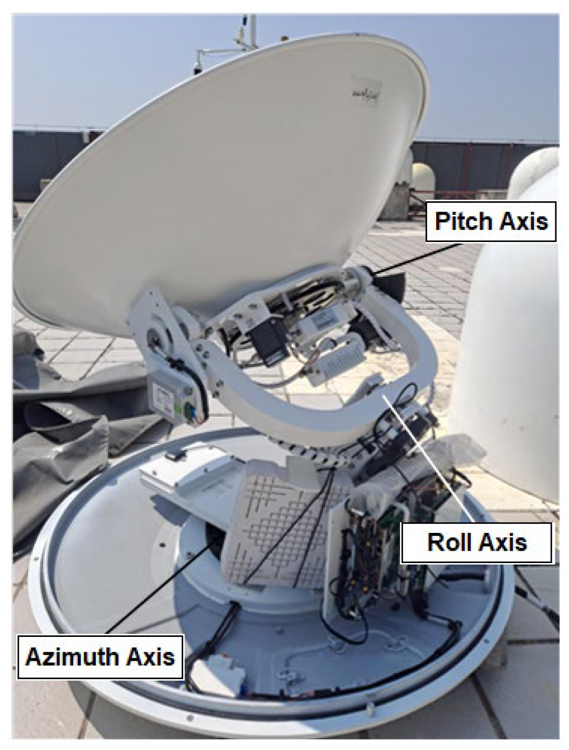
As shown in Figure 1, this is a schematic diagram of a three-axis SOTM mechanical structure. The SOTM is mounted on a base fixed to the carrier, with each axis including a drive motor and a reduction device, typically a gear or belt. Figure 2 shows a real product image of a three-axis SOTM produced and sold by SATPRO M&C Tech Co., Ltd. (A SOTM manufacturer located in Xi’an, China). The three-axis SOTM consists of three subsystems: azimuth, pitch, and roll. By rotating the axes within each subsystem, the antenna can stably track the satellite even when the carrier is in motion. Due to the mechanical structure, there is an acute angle (typically 30 35 ° ) between the pitch axis of the SOTM and the plane of the base [26], making it impossible to directly utilize the MDH [27,28,29] method commonly employed in robotics for modeling. Therefore, this paper introduces the NMDH method from reference [30] to establish the kinematic relationship of the antenna.
The coordinate system configuration of the SOTM system shown in Figure 3. Due to the presence of angle Beta in Figure 3 and the inability to obtain the link lengths required by the conventional MDH method along the z 4 and z 6 axes, coordinate systems 2, 3, and 5 are added to the system. It should be noted that these three coordinate systems do not correspond to any physical entities.
From Figure 3, the corresponding kinematic DH table can be established as shown in Table 1.
From the parameters of the SOTM mechanical structure obtained in Table 1, such as the link length, link twist angle, link offset, and joint rotation angle, the homogeneous transformation matrix T and rotation matrix R can be derived as follows:
T 1 0 = cos θ 1 * sin θ 1 * 0 0 sin θ 1 * cos θ 1 * 0 0 0 0 1 0 0 0 0 1
T 2 1 = 1 0 0 0 0 1 0 0 0 0 1 l 1 0 0 0 1
T 3 2 = 0 1 0 0 cos ( π / 2 + β ) 0 sin ( π / 2 + β ) 0 sin ( π / 2 + β ) 0 cos ( π / 2 + β ) 0 0 0 0 1
T 4 3 = cos ( θ 2 + π ) sin ( θ 2 + π ) 0 l 2 sin β sin ( θ 2 + π ) cos ( θ 2 + π ) 0 0 0 0 1 l 2 cos β 0 0 0 1
T 5 4 = 1 0 0 0 0 1 0 0 0 0 1 l 3 0 0 0 1
T 6 5 = cos θ 3 sin θ 3 0 0 0 0 1 0 sin θ 3 cos θ 3 0 0 0 0 0 1
since
T i + 1 i = R i + 1 i p x i + 1 i p y i + 1 i p z i + 1 i 0 0 0 1
Therefore, Equation (8) is as follows:
R 1 0 = cos θ 1 * sin θ 1 * 0 sin θ 1 * cos θ 1 * 0 0 0 1
R 2 1 = 1 0 0 0 1 0 0 0 1
R 3 2 = 0 1 0 cos ( π / 2 + β ) 0 sin ( π / 2 + β ) sin ( π / 2 + β ) 0 cos ( π / 2 + β )
R 4 3 = cos ( θ 2 + π ) sin ( θ 2 + π ) 0 sin ( θ 2 + π ) cos ( θ 2 + π ) 0 0 0 1
R 5 4 = 1 0 0 0 1 0 0 0 1
R 6 5 = cos θ 3 sin θ 3 0 0 0 1 sin θ 3 cos θ 3 0
According to Equations (8)–(13), the rotation matrix R 6 0 from the coordinate system corresponding to the antenna base to the coordinate system corresponding to the antenna end can be obtained. The calculation of the rotation matrix R 6 0 , i.e., the forward kinematic relationship, is as follows; for simplification of notation, here, s α represents sin α , c α represents cos α , s 2 α represents s i n 2 α and c 2 α represents c o s 2 α .
Let θ 1 = θ 1 ,   θ 2 + π = θ 2 , θ 3 = θ 3 , π 2 + β = φ ; therefore,
R 6 0 = R 1 0 R 2 1 R 3 2 R 4 3 R 5 4 R 6 5 = r 11 r 12 r 13 r 21 r 22 r 23 r 31 r 32 r 33
where
r 11 = c θ 3 s θ 1 c θ 2 c φ c θ 1 s θ 2 + s θ 1 s θ 3 s φ , r 21 = c θ 3 s θ 1 s θ 2 c θ 1 c θ 2 c φ c θ 1 s θ 3 s φ , r 31 = c θ 2 s θ 3 c φ s θ 3 c φ , r 12 = s θ 3 s θ 1 c θ 2 c φ c θ 1 s θ 2 + s θ 1 c θ 3 s φ , r 22 = s θ 3 c θ 1 c θ 2 c φ + s θ 1 s θ 2 c θ 1 c θ 3 s φ , r 32 = c θ 2 s θ 3 s φ c θ 3 c φ , r 13 = s θ 1 s θ 2 c φ + c θ 1 c θ 2 , r 23 = c θ 1 s θ 2 c φ s θ 1 c θ 2 , r 33 = s θ 2 s φ .
Similarly, the overall homogeneous transformation matrix from the coordinate system corresponding to the antenna base to the coordinate system corresponding to the antenna end is shown in Equation (15):
T 6 0 = T 1 0 T 2 1 T 3 2 T 4 3 T 5 4 T 6 5 = R 6 0 p x p y p z 0 0 0 1
where
p x = s θ 1 s φ l 3 s θ 1 c φ s β l 2 + s θ 1 s φ c β l 2 , p y = c θ 1 s φ l 3 + c θ 1 c φ s β l 2 c θ 1 s φ c β l 2 , p z = c φ l 3 + s φ s β l 2 + c φ c β l 2 + l 1 .
From the above formula calculations, it can be seen that there are a large number of trigonometric function operations between coordinate transformations. From the perspective of implementing the SOTM antenna system, specific difficulties include the following: First, trigonometric function calculations typically involve complex mathematical operations, including multiplication, division, square roots, and so on, and this may pose high demands on the computational performance of microprocessors. For some low-cost, low-power microprocessors, this might limit the precision or speed of trigonometric functions, thus occupying more computational resources and time. Second, trigonometric function operations often require high precision, but their floating-point representations are finite, repeated calculations can accumulate errors, and the processor’s computation may be constrained by its hardware bits, leading to precision loss. Additionally, during repeated floating-point multiplication and other operations, significant resources are consumed, and the time cycles are longer; without optimization, this could increase system delays, affecting real-time performance. The degree of support for trigonometric function operations in microprocessors varies depending on the complexity of hardware and software implementations; although some modern microprocessors have built-in specialized instruction sets to accelerate trigonometric function calculations, their costs are high. Furthermore, the method proposed in this section contains a large number of trigonometric function operations, and directly calculating trigonometric functions would result in significant computational delays, which would have negative effect for the SOTM servo systems. Therefore, this paper proposes an easily implementable piecewise linearization method for engineering applications. This method linearizes trigonometric functions in segments, approximating trigonometric functions through segmented straight lines to reduce the computational difficulty for microprocessors and enhance their computational performance.
Due to the phase difference of π / 2 between the sine function and the cosine function, after obtaining a piecewise linearization approximation for the sine function, it is quite straightforward to calculate the cosine function. Because the sine function is a periodic symmetric function, the piecewise linearization approximation scheme provided in this section is designed only for the closed interval [ 0 , π / 2 ] .
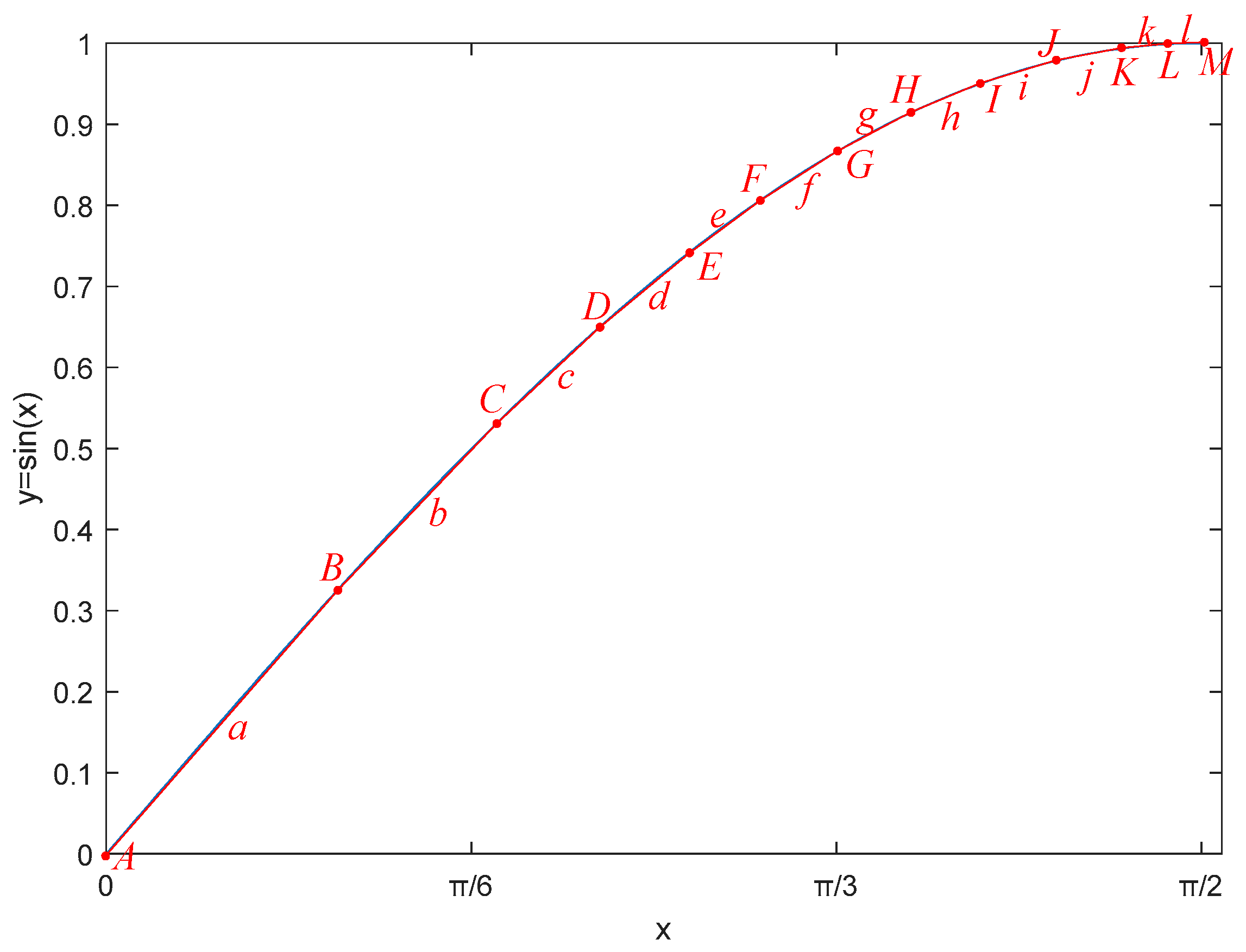
Figure 4 shows an example of the piecewise linearization method for trigonometric functions, where A , B , , M are breakpoint points with respective horizontal coordinates x A , x B , , x M . a , b , and l represents the line segments connecting adjacent breakpoint points. Therefore, the expressions for the aforementioned line segments can be derived as follows:
y a = ς a x + υ a ,   x x A , x B y b = ς b x + υ b ,   x x B , x C y l = ς l x + υ l ,   x x L , x M
In Figure 4, the segmented linear function created by connecting line segments a , b , , l closely approximates a sine function curve. As a result, the computation of complex sine functions is simplified to that of linear functions. To perform the calculation of these linear functions, a microprocessor locally only needs to store the x-coordinate values ( x A , x B , , x M ) of the segment points x A , x B , , x M as well as the slopes ( ς a , ς b , , ς l ) and intercepts ( υ a , υ b , , υ l ) of each segment in order to calculate the values of trigonometric functions through linear functions. This method only requires the microprocessor to have hardware floating-point computation capabilities, placing modest demands on the microprocessor. This allows for calculations utilizing low-cost, high-reliability, yet low-performance microprocessors, thereby reducing hardware costs and enhancing system reliability. It is important to note that the method of selecting segment points in Figure 4 is not unique and can be dynamically adjusted based on the local storage resources of the microprocessor.
Conventional microprocessors typically solve trigonometric functions using Taylor series expansion or Pade approximations. Regardless of the method, both are influenced by the order of approximation; generally, higher orders yield greater accuracy but require more computational resources. For typical microprocessors, considering both accuracy and computation speed, using Taylor series or Pade approximations generally requires dozens to hundreds of floating-point operations. In contrast, the piecewise linearization method designed in this paper requires only two floating-point operations, effectively reducing the consumption of computational resources in the system.

3. Direct Closed-Loop Control Structure Based on Jacobian Operator

3.1. Jacobian Operator

The Jacobian operator is commonly used in the field of robotics to describe the relationship between joint velocities ( q ˙ ) and the end-effector velocity ( X ˙ ) in a robotic mechanical structure. If the robot’s joints move at a certain speed, the Jacobian operator can be used to calculate the velocity of the end-effector in Cartesian space. When q ˙ is known, X ˙ can be calculated through Equation (17):
X ˙ = J q ˙
where q ˙ includes the velocities of all the joints in the mechanical structure, X ˙ includes the linear and angular velocities of the end-effector, and J represents the current location and attitude, i.e., the Jacobian operator.
Facing the complex situation of angles in the mechanical structure of the SOTM antenna, due to its antenna system being a chained structure where the azimuth axis, roll axis, and pitch axis can all move relative to each other, the angular velocities of each axis can be calculated sequentially starting from the base coordinate system. That is, the angular velocity of axis i + 1 is equal to the sum of the angular velocity of axis i and the component caused by the rotation of joint i + 1 . Furthermore, the angular velocity at the antenna’s end must be expressed according to the axis velocities related to the base coordinate system. Therefore, by combining the coordinate transformation relationships between each axis, the rotational angle at the end of the antenna can be ultimately determined. The specific process is as follows:
Due to the fact that each rotational joint of the antenna system rotates around the Z-axis in its own coordinate system, there is the following:
θ i ˙ z = 0 0 θ i ˙
Since the angles of the azimuth, roll, and pitch of the three-axis SOTM antenna are in the same coordinate system, these angular velocities can be summed. Because the angular velocity of the 0th axis of the SOTM being fixed relative to the base frame, ω 0 0 = 0 . As angular velocity describes the rotation of the coordinate system, the rotation matrix in the transformation matrix is used without considering the locational relationship. Therefore, the angular velocity of the azimuth axis is as follows:
ω a z = R 0 1 ω 0 0 + θ ˙ 1 z ^ 1 1 = 0 0 θ 1 ˙
Figure 3 shows that Axis 2 is a virtual coordinate system, while Axis 3 and Axis 5 are auxiliary coordinate systems. Because these coordinate systems do not exist physically, it can be considered that the corresponding joint angles are constantly 0. Consequently, transformations involving the aforementioned coordinate systems do not need to adhere to the standard link transformation rules [31]. Therefore, the angular velocities of the roll axis and pitch axis can be determined as follows:
Using the relationship between the angular velocity of the pitch axis and the components of the angular velocity of the roll drive device (including the roll motor and reduction device), the angular velocity of the roll axis can be determined as follows:
ω c l = R 3 4 ω a z + θ ˙ 2 z ^ 4 4 = 0 0 θ ˙ 1 + θ ˙ 2
Using the relationship between the roll axis angular velocity and the angular velocity components of the pitch drive device (including the pitch motor and reduction device), the angular velocity of the pitch axis can be determined as follows:
ω e l = R 5 6 ω c l + θ ˙ 3 z ^ 6 6 = sin θ 3 ( θ ˙ 1 ) s i n ( θ 3 ) ( θ ˙ 2 ) cos θ 3 ( θ ˙ 1 ) c o s ( θ 3 ) ( θ ˙ 2 ) θ ˙ 3
The angular velocity of the antenna must be expressed based on the axis velocities associated with the reference coordinate system, so the angular velocity of the antenna relative to the reference coordinate system can be determined as follows:
ω e f f e c t o r b a s e = R 6 0 ω e l
Since the Jacobian operator can be used to describe the mutual relationships between the joints of a linkage and their effects on the motion mechanism, the Jacobian matrix is calculated below to describe the relationship between the changes in joint angular velocities for azimuth, roll, and pitch and the changes in end-effector angular velocity.
Since
ω e f f e c t   o r b a s e = J ( ω ) θ ˙ 1 θ ˙ 2 θ ˙ 3
therefore,
J ω = j 11 j 12 j 13 j 21 j 22 j 23 j 31 j 32 j 33
where
j 11 = c θ 3 s θ 3   s θ 1 c θ 2 c φ c θ 1 s θ 2 + c 2   θ 3 s θ 1 s θ 2 c θ 1 c θ 2 c φ + s θ 1 s 2   θ 3 s φ c θ 1 c θ 3 s θ 3 s φ , j 21 = s 2   θ 3 s θ 1 c θ 2 c φ c θ 1 s θ 2 + c θ 3 s θ 3 c θ 1 c θ 2 c φ s θ 1 s θ 2 + s θ 1 s θ 3 c θ 3 s φ c θ 1 c 2   θ 3 s φ , j 31 = s θ 1 s θ 2 s θ 3 c φ + c θ 1 c θ 2 s θ 3 c θ 1 s θ 2 c θ 3 c φ s θ 1 c θ 2 c θ 3 , j 12 = c θ 3 s θ 3 s θ 1 c θ 2 c φ c θ 1 s θ 2 + c 2   θ 3 s θ 1 s θ 2 c θ 1 c θ 2 c φ s θ 1 s 2   θ 3 s φ + c θ 1 c θ 3 s θ 3 s φ , j 22 = s 2   θ 3 s θ 1 c θ 2 c φ c θ 1 s θ 2 c θ 3 s θ 3 c θ 1 c θ 2 c φ s θ 1 s θ 2 s θ 1 c θ 3 s θ 3 s φ + c θ 1 c 2   θ 3 s φ , j 32 = s θ 1 s θ 2 s θ 3 c φ c θ 1 c θ 2 s θ 3 + c θ 1 s θ 2 c θ 3 c φ + s θ 1 c θ 2 c θ 3 , j 13 = c θ 2 s θ 3 c φ s θ 3 c φ , j 23 = c θ 2 s θ 3 c φ s θ 3 c φ , j 33 = s θ 2 s φ ,

3.2. Direct Closed-Loop Control Structure

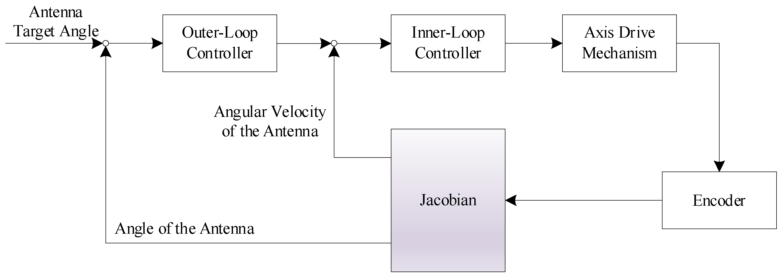
The three-axis SOTM antenna servo control system is typically designed with a closed-loop control structure [32,33,34]. However, only the rotational states of each axis, measured by encoders, can be obtained as feedback, and the antenna-pointing direction is adjusted through the controller; the closed-loop control structure is illustrated in Figure 5. However, this method introduces errors in the feedback signal, ultimately affecting control accuracy. The closed-loop control in Figure 5 utilizes the rotational angles of each axis to represent the antenna-pointing direction. However, the actual rotational angles of the antenna during operation cannot be obtained, making this closed-loop control essentially an indirect closed-loop control structure. Using the Jacobian operator described in Section 3.1, the antenna’s rotational state can be derived from the rotational states of the axes. From this perspective, incorporating the Jacobian operator into the indirect closed-loop control structure shown in Figure 5 allows for the construction of a direct closed-loop control. In other words, the direct closed-loop control structure can obtain antenna orientation information directly as feedback through the kinematic relationships between the antenna’s axes and the Jacobian operator. This direct feedback method eliminates the errors present in the feedback of the indirect method, thereby improving the system’s control accuracy. The direct closed-loop control structure for SOTM based on the Jacobian operator is shown in Figure 6.
The direct closed-loop structure in Figure 6 consists of an outer loop for the position and an inner loop for the velocity, which, respectively, control the system’s stability and rapid response. The outer position control uses the angular velocity and angle of each axis drive mechanism measured by encoders. These measurements are then combined with the Jacobian operator to obtain the antenna end’s angular velocity and angle, which serve as feedback for the inner velocity loop and outer position loop, respectively. The difference between the outer loop feedback (i.e., antenna angle) and the target antenna angle yields the outer loop deviation value, which is used as the input for the outer position controller. The output of the outer position loop controller serves as the input for the inner velocity loop, which is the desired value for the inner loop. The difference between this desired value and the inner loop feedback (i.e., antenna angular velocity) yields the inner loop deviation, which is used as the input for the inner velocity controller. The output of the inner velocity controller acts as the control command for the axis drive mechanisms, thereby ensuring the antenna accurately points to the target communication satellite.

4. Controller Design

The direct closed-loop control structure proposed in this paper is a kind of dual closed-loop control structure. Since the control target is the antenna angle, the outer loop is a location loop, while the inner loop utilizes a velocity loop. A PID control is the most commonly used control method in SOTM servo control systems; however, for a PID controller, it is a weighted sum of the proportional, integral, and derivative terms. Increasing the proportional gain can enhance speed, but it may lead to increased overshoot. Conversely, decreasing the proportional gain can reduce overshoot but slows down the response. This presents a contradiction between rapidity and overshoot. That is, if one wishes for the system to respond quickly and converge to the target state, it will cause a significant overshoot, whereas if one aims to reduce or eliminate the overshoot of the system response, the speed at which the system responds and converges to the target state will slow down.
For the SOTM servo control system, it is desired that the antenna rapidly and accurately adjusts to the target direction. If the system has a fast response rate but a large overshoot, the antenna may continue to move after accurately pointing to the satellite, causing a deviation from the satellite. Conversely, if the system has minimal (or even zero) overshoot but a slow response speed, the antenna may experience changes in carrier attitude and location before it accurately points to the satellite, also potentially leading to misalignment with the satellite. Therefore, SOTM servo control systems should aim to minimize or eliminate overshoot while satisfying speed requirements. However, traditional PID controllers struggle to meet such demands.
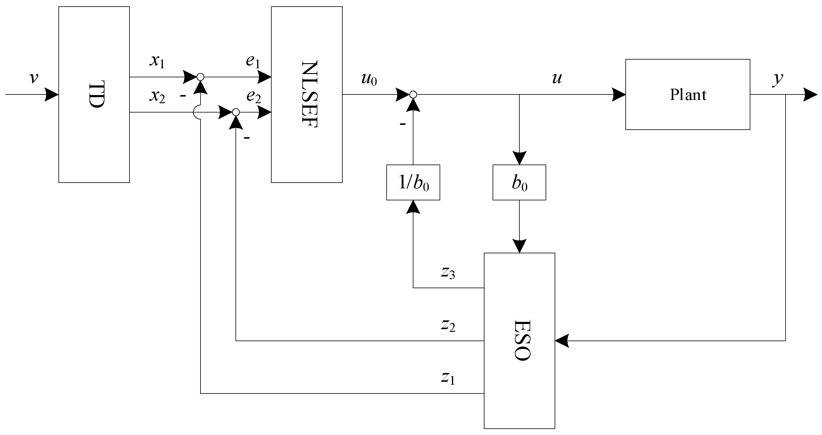
In an ADRC, there is a tracking differentiator that contains an optimal synthesis function that can achieve the optimal configuration for the system’s transition process, ensuring a rapid system response while keeping overshoot to a minimum or even eliminating it altogether [35]. An ADRC, with the advantages of a PID control, such as simplicity, wide adaptability, and independence from precise mathematical models of objects, also exhibits strong robustness, rapid response without overshoot, and ease of application. Therefore, we select an ADRC as the inner loop and outer loop controllers of the servo system. Figure 7 illustrates the ADRC structure.
The core framework of an ADRC consists of three components: a tracking differentiator (TD), Extended State Observer (ESO), and Nonlinear State Error Feedback (NLSEF). Next, we will introduce each part separately.
The discrete TD model is as follows:
υ 1 k + 1 = υ 1 k + s t · υ 2 k υ 2 k + 1 = υ 2 k + s t · f h f h = f h a n v 1 k υ k , υ 2 k , r 0 , h 0
In Equation (25), υ denotes the input; υ 1 denotes the estimate of the input by the TD, which tracks the input signal; υ 2 denotes the estimate of the derivative of the input by the TD; s t is the sampling period; and r and h 0 are the speed factor and filtering factor, respectively. The function f h a n is the previously mentioned optimal synthesis function, with the following expression:
f h a n υ 1 , υ 2 , r , h = d = r s t 2 a 0 = s t υ 2 y = υ 1 + a 0 a 1 = d d + 8 y a 2 = a 0 + a 1 d / 2 s i g n y a = a 0 + y f s g y , d + a 2 1 f s g y , d
In Equation (26), the optimal synthesis function f h a n ( x 1 , x 2 , r , h ) , where function s i g n represents the sign function, is described, and Equation (27) is the expression for function f s g .
f s g y , d = s i g n x + d s i g n x d 2
There are generally two expressions for NLSEF, one of which is as follows:
u 0 = β 1 f a l e 1 , a 1 , δ + β 2 f a l e 2 , a 2 , δ
Another way of expression is as follows:
u 0 = f h a n e 1 , c e 2 , r , h 1
In Equations (28) and (29), e 1 represents the error signal and e 2 represents the differential of the error signal, while β 1 , β 2 , a 1 , a 2 , h 1 , c , and δ are the controller parameters, and they are adjustable.
The model of discrete EOS is as follows:
ε 1 = z 1 k y k z 1 k + 1 = z 1 k + s t · z 2 k β 01 ε 1 z 2 k + 1 = z 2 k + s t · z 3 k β 02 f a l ε 1 , 0.5 , δ + b 0 u z 3 k + 1 = z 3 k s t · β 03 f a l ε 1 , 0.25 , δ
where z 1 denotes the estimate of the state variable observed by the ESO, z 2 denotes the estimate of the state differential observed by the ESO, z 3 denotes the estimate of the total disturbance of the system observed by the ESO, and s t is the discrete time sampling period. In Equation (30), β 01 , β 02 , β 03 , and δ are the controller parameters, and they are adjustable. Equation (31) describes the traditional f a l function, i.e., f a l t r a d in Equation (31).
f a l t r a d α , a , δ = α δ 1 a , α δ s i g n α · α a , α > δ
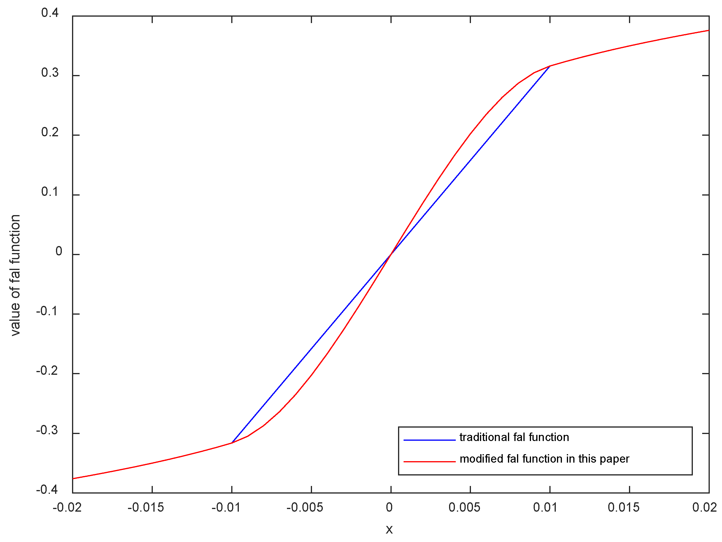
In a conventional ADRC, the traditional f a l function ( f a l t r a d ) is continuous, but it has nondifferentiable points, namely the points where α takes the values δ and δ . The left and right derivatives of the f a l t r a d function at these two points is not equal. These points are cusps, indicating f a l t r a d is a continuous but non-smooth function. Research indicates that both the continuity and smoothness of the f a l function will significantly impact the control effectiveness of the ADRC. In Equation (31), the f a l function has adverse effects on the control system [17]. Due to these reasons, we introduce a modified f a l function ( f a l m o d ); Equation (31) describes the f a l m o d function.
f a l m o d α , a , δ = γ 1 sin α + γ 2 tan α ,   α δ s i g n ( α ) x a ,       α > δ  
where
γ 1 = δ a a δ a 1 sin δ cos δ sin 3 δ , γ 2 = a δ a 1 sin δ δ a cos δ sin δ tan 2 δ .
It can be easily verified that the f a l m o d function is a smooth and continuous function at the points α = δ and α = δ , and it is symmetric about the origin of the coordinate system. The functions f a l t r a d and f a l m o d are shown in Figure 8.
For the f a l m o d function, the function equation is known, making it relatively simple mathematically. However, when considering practical applications in system engineering, the equation involves complex operations that consume significant computational resources and time for a microprocessor, especially concerning low-cost, high-reliability, and low-power-consumption microprocessors. Therefore, a segmented linearization method in Section 2 can be employed to linearize the f a l m o d function, reducing the microprocessor resource utilization, decreasing computational delays, and enhancing system efficiency. Similar to the method outlined in Section 2, further elaboration is omitted here.

5. Experimental Analysis

In this section, we will verify the effectiveness of the scheme proposed in the previous section through real engineering experiments. The experimental equipment utilized M60 SOTM antenna (Figure 2). First, a comparative experiment was conducted between the indirect closed-loop control structure (Figure 5) and the direct closed-loop control structure (Figure 6) designed in Section 3 to validate the control effectiveness of the proposed direct closed-loop structure. Here, both of the closed-loop structures employed PID controllers. Subsequently, a comprehensive validation of the designed scheme presented in this paper was conducted by integrating the direct closed-loop structure designed in Section 3 with the improved ADRC algorithm in Section 4.

5.1. Experimental Environment

Address: SATPRO M&C Tech Co., Ltd., Xi’an, P.R. China;
Date: 17 May 2024;
Weather: Sunny, 34 °C;
Location: 108.8522° E, 34.3674° N;
Target Satellite: YATAI 6D GEO;
SOTM Manufacture: SATPRO (Xi’an, China);
SOTM Working Band: Ku Band;
SOTM Receiving Frequency: 10.7–12.75 GHz;
SOTM Transmitting Frequency: 13.75–14.5 GHz;
Azimuth range of the Swing Platform: −15–15°;
Pitch range of the Swing Platform: −15–15°;
Roll range of the Swing Platform: −15–15°;
SOTM antenna Azimuth Scanning Range: 0–360°;
SOTM antenna Pitch Scanning Range: 0–90°;
SOTM antenna Roll Scanning Range: −15–15°.
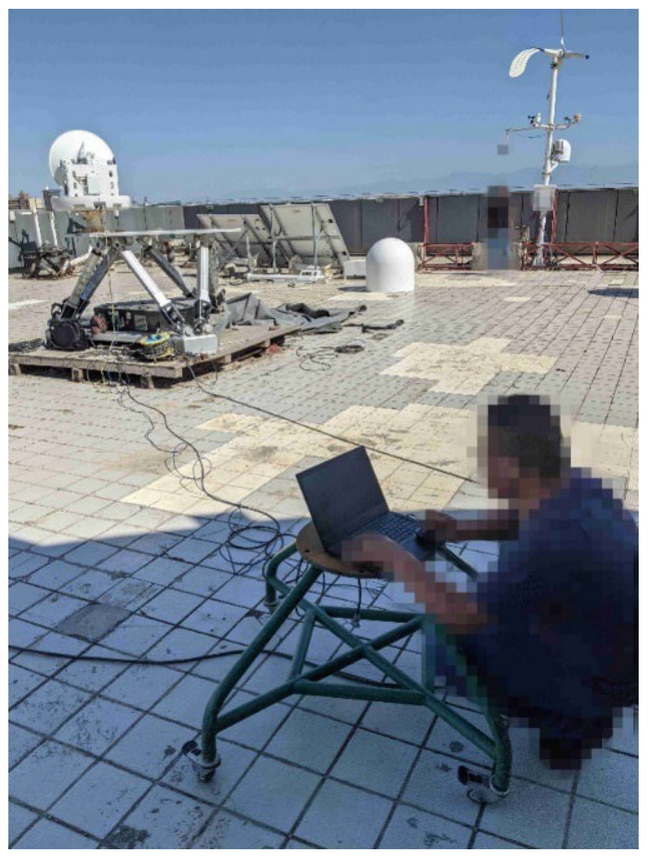
The experimental site is shown in Figure 9.

5.2. Experimental Results and Analyses

First, experiments were conducted to compare the conventional indirect closed-loop structure with the direct closed-loop structure proposed in Section 3. Each experiment lasted over 20 min, and a conventional PID algorithm was employed in the control system. Due to the experiment lasting over 20 min and involving a large amount of data, the time axis of a single graph is limited. Including too much data in one graph would result in the loss of many details. Additionally, since the overall trend of the data was consistent, we randomly selected continuous 200 s of data for plotting to provide readers with a clearer view of the experimental data details. After each experiment, we compiled the data from the entire process in tabular form, obtaining the statistical characteristics of the relevant parameters to strengthen the validation of the scheme’s effectiveness.
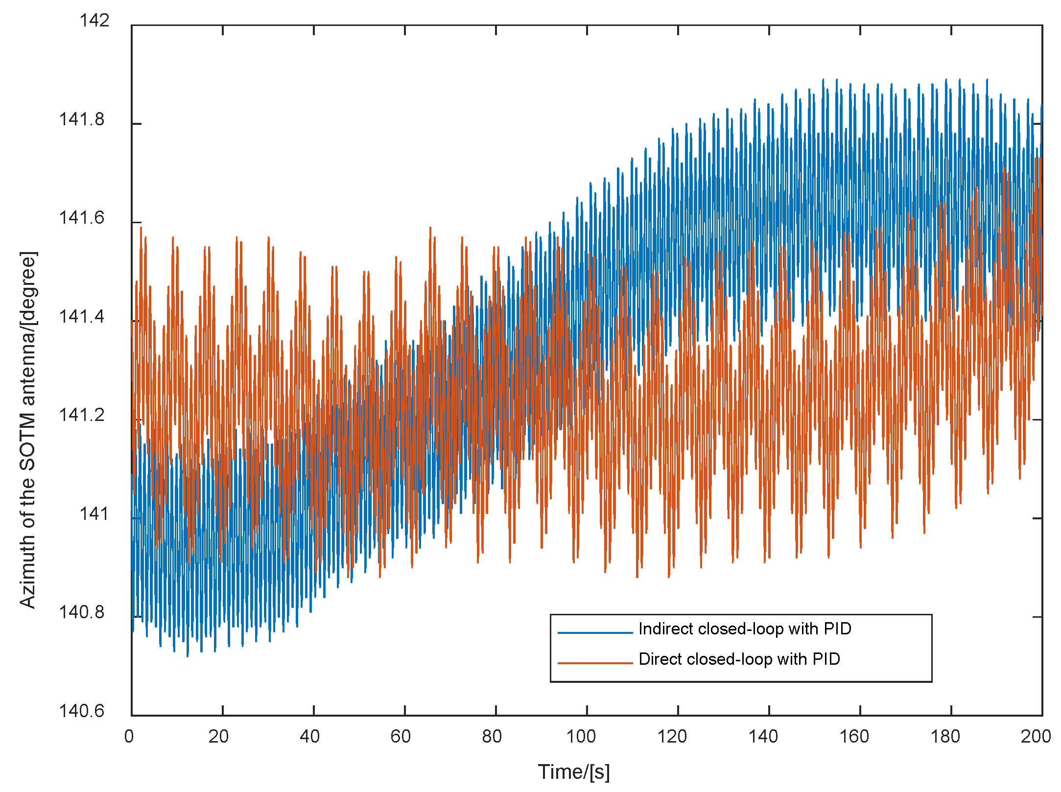
As shown in Figure 10, the azimuth pointing of the SOTM antenna with the conventional indirect closed-loop structure and the direct closed-loop control proposed in Section 3 are presented separately. From Figure 10, it can be observed that compared to the conventional indirect closed-loop structure, when using the direct closed-loop structure, the azimuth pointing of the antenna exhibits less fluctuation, indicating that with the direct closed-loop structure designed in Section 3, the azimuth pointing of the antenna is more stable.
As shown in Figure 11, the pitch pointing of the SOTM antenna with the conventional indirect closed-loop structure and the direct closed-loop structure proposed in Section 3 are presented separately. From Figure 11, it can be observed that compared to the conventional indirect closed-loop structure, the direct closed-loop structure designed in Section 3 results in smaller fluctuations in the pitch pointing of the antenna. This indicates that the employment of the direct closed-loop structure designed in Section 3 leads to a more stable pitch pointing of the antenna.
Considering the experimental results of azimuth and pitch angle from Figure 10 and Figure 11, we can conclude that when compared to the conventional indirect closed-loop structure, the tracking effectiveness of the antenna towards the satellite is improved when utilizing the direct closed-loop structure designed in Section 3.
Qualitative comparisons of a random 200 s segment within the experimental process have been presented previously. The following provides quantitative results for the entire experiment, using statistical data such as maximum, minimum, mean, range, and variance for comparison. The experimental results are shown in Table 2. Notably, the unit for all data except variance is degrees.
According to Table 2, compared to the conventional indirect closed-loop structure, when using the direct closed-loop structure designed in Section 3, the azimuth fluctuation range of the antenna decreased by 20.51%; meanwhile, the pitch fluctuation range decreased by 34.12%. We can indicate that with the direct closed-loop structure, the stability of the antenna pointing towards the communication satellite is higher.
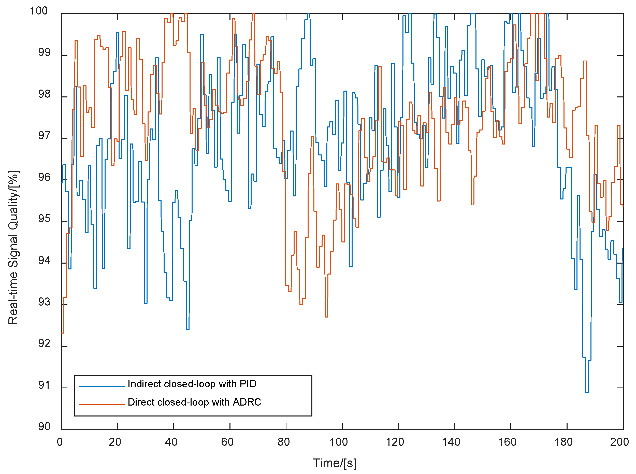
The purpose of the SOTM servo control is to ensure the accurate pointing of the antenna’s azimuth and pitch. Generally, the results shown in Figure 10 and Figure 11 and Table 2 can effectively demonstrate the validity of the proposed scheme. This paper further verifies the effectiveness of the scheme from the perspective of communication performance by comparing common communication-related metrics in the SOTM field, such as the real-time automatic gain control level (RTAGCL), real-time signal-to-noise ratio (RTSNR), and real-time signal quality (RTSQ). This comparison is reasonable, as under the same external conditions, the more precisely the antenna is pointed, the better the communication performance of the SOTM system.
Next, we will select commonly used metrics for evaluating satellite communication effectiveness, including the RTAGCL, RTSNR, and RTSQ, to verify the satellite communication performance throughout the entire experiment.
As shown in Figure 12, the RTAGCLs of the SOTM with the indirect closed-loop structure (Figure 5) and the direct closed-loop structure designed in Section 3 are presented separately. From Figure 12, it can be seen that compared to the conventional indirect closed-loop structure, the direct closed-loop structure designed in Section 3 results in higher RTAGCLs, indicating better communication effectiveness in the SOTM antenna system.
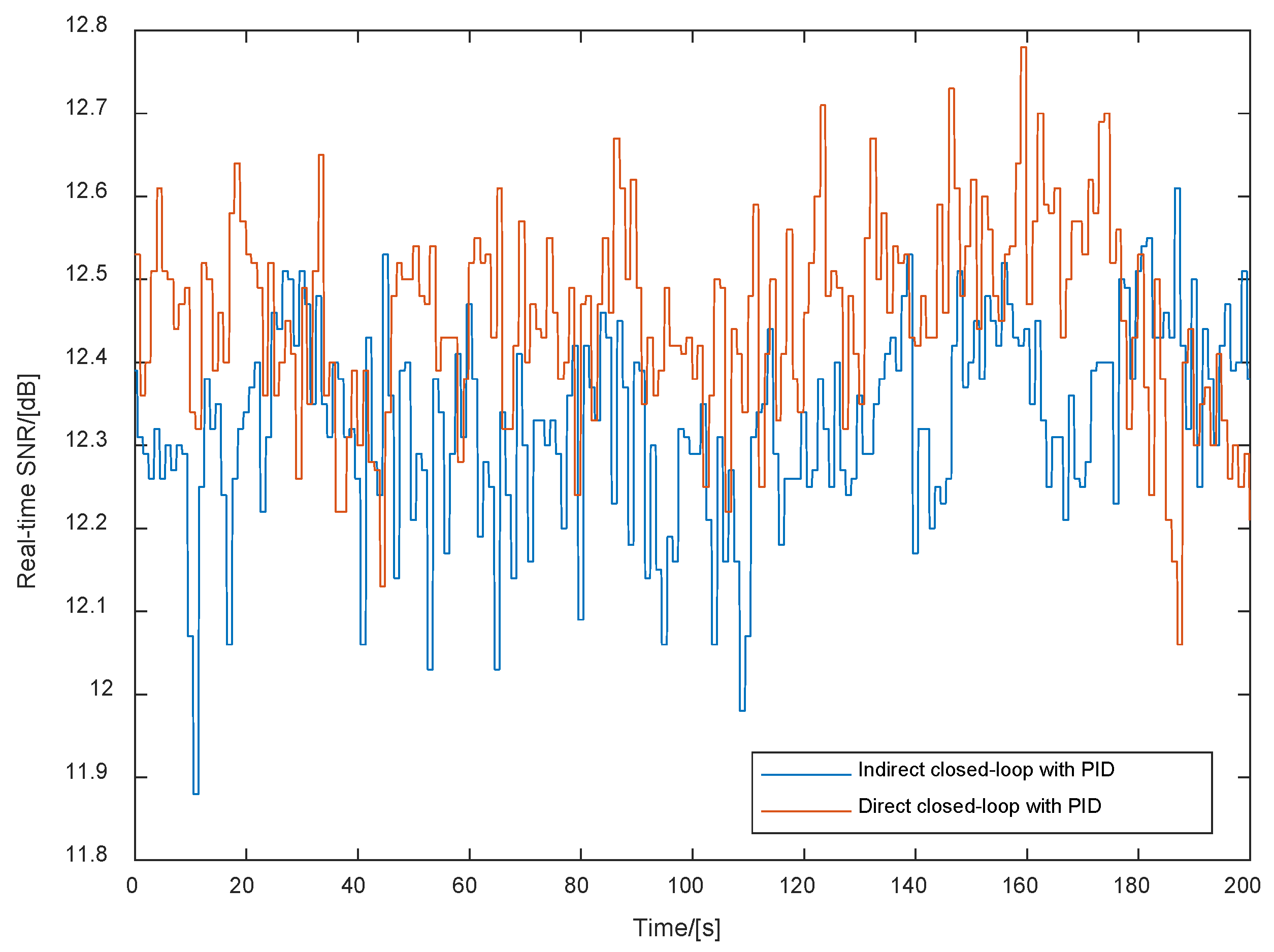
As shown in Figure 13, the RTSNR of the SOTM with the conventional indirect closed-loop structure and the direct closed-loop structure designed in Section 3 are presented separately. From Figure 13, it can be seen that compared to the conventional indirect closed-loop structure, the direct closed-loop structure designed in Section 3 results in a higher RTSNR, indicating better communication effectiveness in the SOTM antenna system.
As shown in Figure 14, the RTSQ of the SOTM with the conventional indirect closed-loop structure and the direct closed-loop structure designed in Section 3 are presented separately. From Figure 14, it can be seen that compared to the conventional indirect closed-loop structure, the direct closed-loop structure designed in Section 3 results in a higher RTSQ, indicating better communication effectiveness in the SOTM antenna system.
Qualitative comparisons of a random 200 s segment within the experimental process have been presented previously. The following provides quantitative results for the entire experiment, using statistical data such as mean and variance for comparison. The experimental results are shown in Table 3. Notably, the units for the RTAGCL, RTSNR, and RTSQ are volts, decibels, and percentages, respectively.
As shown in Table 3, compared to the conventional indirect closed-loop structure, the direct closed-loop structure designed in Section 3 resulted in improvements in the RTAGCL, RTSNR, and RTSQ of the SOTM. Simultaneously, the variances of these three indicators decreased, indicating that when an improved ADRC is employed, the satellite communication effectiveness of the SOTM is enhanced, leading to stabler satellite communication performance. It should be noted that when SOTM communication is normal, the value ranges of the RTAGCL, RTSNR, and RTSQ are relatively narrow. Therefore, the values of the RTAGCL, RTSNR, and RTSQ used for comparison in Table 3 will not show significant changes.
Taking all the experimental results into consideration, it can be concluded that compared to the conventional indirect closed-loop structure, the direct closed-loop structure designed in Section 3 shows better precision in pointing towards the target communication satellite. Additionally, the SOTM’s communication effectiveness is superior when using this control method, indicating that the direct closed-loop structure designed in Section 3 is suitable for the development of SOTM servo systems.
The preceding experiments have verified the control effectiveness of the direct closed-loop control. Next, a comprehensive validation of the scheme proposed in this paper will be conducted by integrating the direct closed-loop control and the improved ADRC.
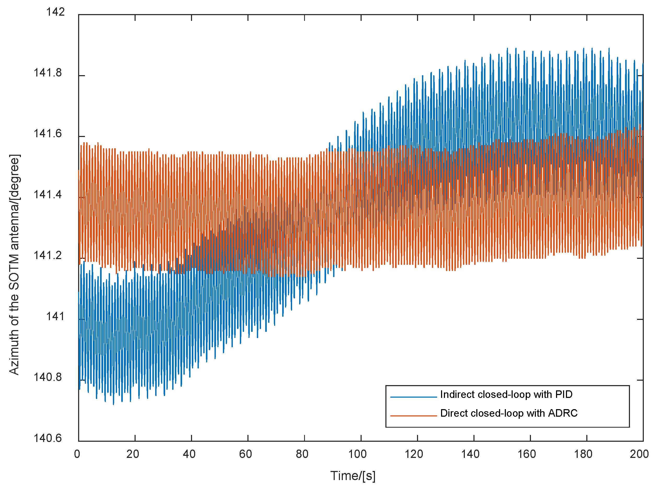
Figure 15 shows the antenna azimuth pointing using the conventional indirect closed-loop PID control and the direct closed-loop ADRC control proposed in this paper. From Figure 15, it can be observed that compared to the conventional scheme, the azimuth fluctuations of the SOTM antenna are smaller when using the direct closed-loop ADRC scheme proposed in this paper, indicating that the antenna’s azimuth pointing is more stable with the direct closed-loop ADRC control structure.
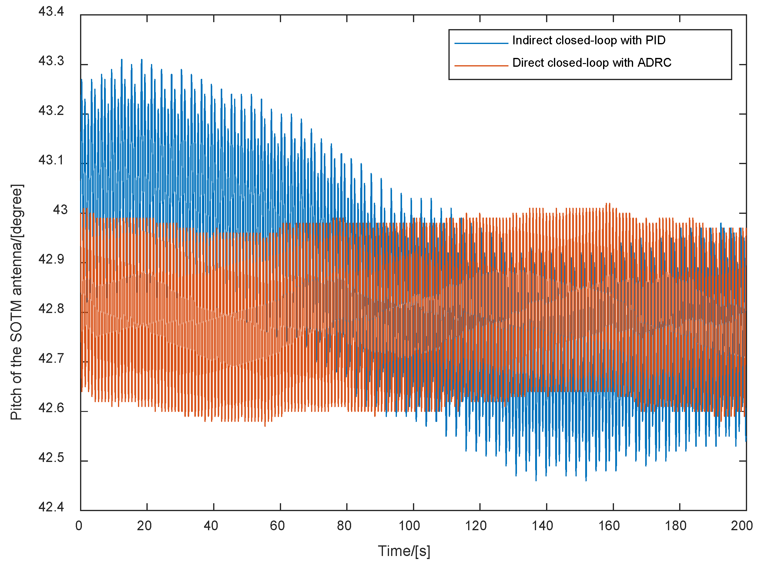
Figure 16 shows the antenna pitch pointing using the conventional indirect closed-loop PID control and the direct closed-loop ADRC control proposed in this paper. From Figure 16, it can be observed that compared to the conventional scheme, the pitch fluctuations of the SOTM antenna are smaller when using the direct closed-loop ADRC scheme proposed in this paper, indicating that the antenna’s pitch pointing is more stable with the direct closed-loop ADRC control structure.
Qualitative comparisons of a random 200 s segment within the experimental process have been presented previously. The following provides quantitative results for the entire experiment, using statistical data such as maximum, minimum, mean, range, and variance for comparison. The experimental results are shown in Table 4. Notably, the unit for all data except variance is degrees.
Combining Table 2 and Table 4, we can conclude that compared to the direct control scheme with PID, the azimuth fluctuation range of the antenna is reduced by 31.18%, and the pitch fluctuation range is reduced by 7.14% when using the direct closed-loop control structure in Section 3 and the improved ADRC scheme in Section 4. Compared to the conventional indirect control scheme, the azimuth fluctuation range of the SOTM is reduced by 45.30%, and the pitch fluctuation range is reduced by 38.82%. This indicates that the comprehensive adoption of the direct closed-loop structure in Section 3 and the improved ADRC scheme in Section 4 can effectively enhance the pointing stability of the antenna towards the target satellite.
Next, based on the RTAGCL, RTSNR, and RTSQ in the comprehensive SOTM system, the communication effect of the SOTM system in the experimental process of introducing the improved ADRC algorithm in the direct closed-loop control structure is verified.
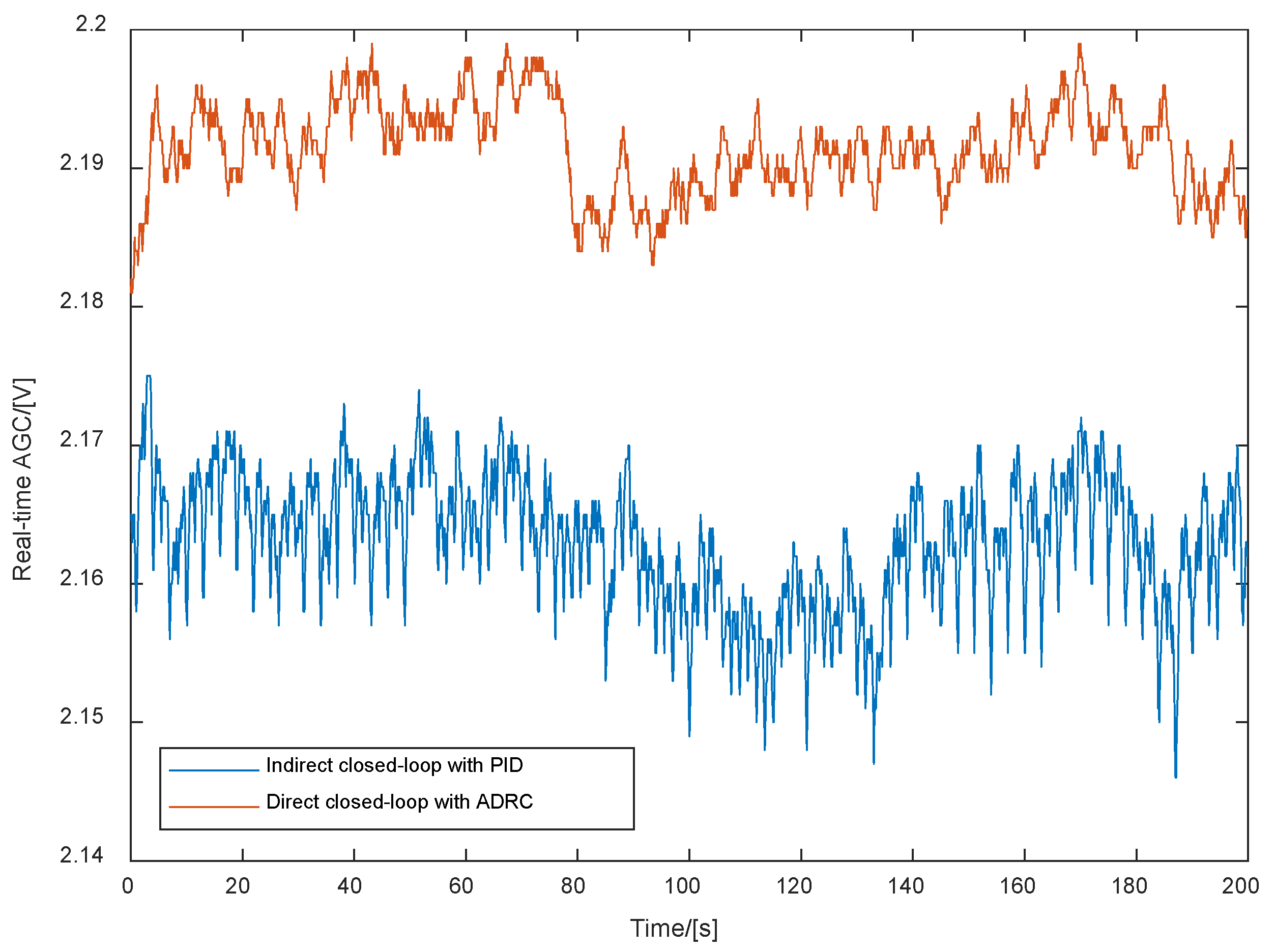
Figure 17 shows the RTAGCL of the SOTM system using the conventional indirect closed-loop PID control and the direct closed-loop ADRC control proposed in this paper. From Figure 17, it can be observed that compared to the conventional scheme, the amplitude of the RTAGCL in the SOTM system is higher when using the proposed direct closed-loop ADRC scheme, indicating that the communication performance of the SOTM system is improved with the direct closed-loop ADRC control structure.
Figure 18 shows the RTSNR of the SOTM system using the conventional indirect closed-loop PID control and the direct closed-loop ADRC control proposed in this paper. From Figure 18, it can be observed that compared to the conventional scheme, the amplitude of the RTSNR in the SOTM system is higher when using the proposed direct closed-loop ADRC scheme, indicating that the communication performance of the SOTM system is improved with the direct closed-loop ADRC control structure.
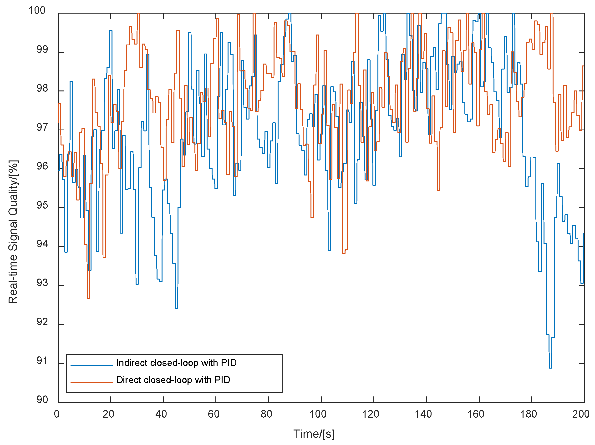
Figure 19 shows the RTSQ of the SOTM system using the conventional indirect closed-loop PID control and the direct closed-loop ADRC control proposed in this paper. From Figure 19, it can be observed that compared to the conventional scheme, the amplitude of the RTSQ in the SOTM system is higher when using the proposed direct closed-loop ADRC scheme, indicating that the communication performance of the SOTM system is improved with the direct closed-loop ADRC control structure.
Qualitative comparisons of a random 200 s segment within the experimental process have been presented previously. The following provides quantitative results for the entire experiment, using statistical data such as mean and variance for comparison. The experimental results are shown in Table 5. Notably, the units for the RTAGCL, RTSNR, and RTSQ are volts, decibels, and percentages, respectively.
Combining Table 3 and Table 5, it can be concluded that compared to direct control schemes with PID, the real-time averages of the RTAGCL, RTSNR, and RTSQ of the SOTM system are further improved by the proposed direct closed-loop control structure and improved ADRC scheme. Compared to conventional indirect control approaches, the RTAGCL of the SOTM has increased by 0.026, the RTSNR average has increased by 0.26, and the signal quality average has increased by 0.78, with reductions in the variances of these three metrics. It can be concluded that integrating the direct closed-loop control structure and the improved ADRC scheme proposed in this paper can effectively enhance the communication performance of the SOTM system.
It should be noted that for the 60-size SOTM antenna used in this experiment, the normal operating ranges for the AGC, signal-to-noise ratio, and signal quality are quite narrow. Based on the empirical data obtained by SATPRO M&C Tech Co., Ltd., during long-term testing, for the AGC, the maximum value during operation is generally below 2.20; below 2.13, the communication quality significantly deteriorates, and below 2.10, communication is nearly interrupted. For the signal-to-noise ratio, the maximum value is typically below 12.9; the communication quality notably worsens below 11.8 and is nearly interrupted below 11.0. For the signal quality, the maximum value during operation is 100%; below 92%, the communication quality deteriorates significantly and is nearly interrupted below 85%. Thus, it is evident that for these three indicators, the SOTM system maintains good communication performance within a very narrow range. This also explains why the values of the RTAGCL, RTSNR, and RTSQ used for comparison in Table 3 and Table 5 did not show significant changes. Therefore, even minor changes in these metrics can significantly enhance the communication effectiveness of the SOTM system.
Based on all the experimental results, it can be concluded that compared to the conventional indirect closed-loop control, the combined use of the direct closed-loop control structure and the improved ADRC scheme proposed in this paper results in higher accuracy for the SOTM antenna in tracking communication satellites. Furthermore, the communication performance and stability of the SOTM system are superior, indicating that the proposed solution is suitable for application in the development of SOTM systems.

6. Conclusions

To address the issues existing in the indirect closed-loop control structure of traditional three-axis SOTM antenna, this paper proposes a direct closed-loop control structure. The scheme designed in this paper can be applied to three-axis SOTM systems with different diameters and mechanical sizes. In the future, it can also be utilized for dual-axis SOTM systems running in non-equatorial regions, as it only requires maintaining the roll axis as a constant value of 0, meaning the roll axis remains unchanged. First, the kinematic relationships between the antenna and each axis are determined using the DH method. Then, the relationship between the angles and angular velocities of antenna rotation and the angles and angular velocities of axis rotations is derived using the Jacobian operator as the feedback quantity. In order to meet the control requirements of fast response and no overshoot in the three-axis SOTM antenna, an ADRC algorithm based on smooth continuous functions is introduced as the inner and outer loop controller algorithms in the direct closed-loop control structure. To improve the engineering feasibility of the solution and address the high-performance requirements of nonlinear elements in the solution for microprocessors, a piecewise linearization method is introduced to convert computationally intensive nonlinear operations into less computationally resource intensive linear operations. Finally, the experimental validation of the proposed solution is conducted. The results demonstrate that compared to the indirect closed-loop control, the direct closed-loop control scheme designed in this paper can enhance the pointing accuracy of the three-axis SOTM antenna and also improve communication effectiveness.

Author Contributions

Conceptualization, J.R. and X.J.; methodology, J.R., L.H., S.S., and Y.W.; software, J.R. and J.L.; validation, X.J., S.S., J.L., and Y.W.; formal analysis, J.R.; investigation, J.R. and J.L.; resources, L.H.; data curation, X.J. and L.H.; writing—original draft preparation, J.R., X.J. and L.H.; writing—review and editing, J.R., X.J., S.S., Y.W. and J.L.; supervision, X.J. and Y.W.; project administration, X.J. and L.H.; funding acquisition, X.J. All authors have read and agreed to the published version of the manuscript.

Funding

This study was funded by Qin Chuang Yuan Construction of Two Chain Integration Special Project, grant number 23LLRH0006.

Data Availability Statement

The data used to support the findings of this study are included within the article.

Conflicts of Interest

Authors Lei Han and Xiaoxiang Ji were employed by SATPRO M&C Tech Co., Ltd. The remaining authors declare that the research was conducted in the absence of any commercial or financial relationships that could be construed as potential conflicts of interest.

References

  1. George, A.; Fernando, M.; George, A.; Baskar, T.; Pandey, D. Metaverse: The Next Stage of Human Culture and the Internet. Int. J. Adv. Res. Trends Eng. Technol 2021, 8, 1–10. [Google Scholar]
  2. Kozyreva, A.; Lewandowsky, S.; Hertwig, R. Citizens Versus the Internet: Confronting Digital Challenges with Cognitive Tools. Psychol. Sci. Publ. Int. 2021, 21, 103–156. [Google Scholar] [CrossRef] [PubMed]
  3. Shaengchart, Y.; Tanpat, K.; Smich, B. Factors Influencing the Effects of the Starlink Satellite Project on the Internet Service Provider Market in Thailand. Technol. Soc. 2023, 74, 102279. [Google Scholar] [CrossRef]
  4. Cui, G.; He, Q.; Chen, F.; Jin, H.; Yang, Y. Trading off Between User Coverage and Network Robustness for Edge Server Placement. IEEE Trans. Cloud Comput. 2020, 10, 2178–2189. [Google Scholar] [CrossRef]
  5. Benavente-Peces, C.; Herrero-Sebastian, I. Worldwide Coverage Mobile Systems for Supra-Smart Cities Communications: Featured Antennas and Design. Smart Cities 2020, 3, 556–584. [Google Scholar] [CrossRef]
  6. Hassan, N.; Huang, C.; Yuen, C.; Ahmad, A.; Zhang, Y. Dense Small Satellite Networks for Modern Terrestrial Communication Systems: Benefits, Infrastructure, and Technologies. IEEE Wirel. Commun. 2020, 27, 96–103. [Google Scholar] [CrossRef]
  7. Al-Ahmed, S.; Shakir, M.; Zaidi, S. Optimal 3D UAV Base Station Placement by Considering Autonomous Coverage Hole Detection, Wireless Backhaul and User Demand. J. Commun. Netw. 2020, 22, 467–475. [Google Scholar] [CrossRef]
  8. Pang, X.; Sheng, M.; Zhao, N.; Tang, J.; Niyato, D.; Wong, K. When UAV Meets IRS: Expanding Air-Ground Networks via Passive Reflection. IEEE Wirel. Commun. 2021, 28, 164–170. [Google Scholar] [CrossRef]
  9. Li, K.; You, L.; Wang, J.; Gao, X.; Tsinos, C.; Chatzinotas, S.; Ottersten, B. Downlink Transmit Design for Massive MIMO LEO Satellite Communications. IEEE Trans. Commun. 2021, 70, 1014–1028. [Google Scholar] [CrossRef]
  10. Chen, Z.; Qing, X.; Tang, X.; Liu, W.; Xu, R. Phased Array Metantennas for Satellite Communications. IEEE Commun. Mag. 2020, 60, 46–50. [Google Scholar] [CrossRef]
  11. Han, L.; Li, G.; Ren, J.; Ji, X. Synthetic Deviation Correction Method for Tracking Satellite of the SOTM Antenna on High Maneuveribility Carriers. Electronics 2022, 11, 3732. [Google Scholar] [CrossRef]
  12. Gunnar, R.; James, D. Servo requirements for FCC VMES compliance: Servo performance levels required to meet FCC VMES pointing requirements for satcom-on-the-move antennas on ground vehicles. In Proceedings of the 2010 Military Communications Conference (2010—MILCOM), San Jose, CA, USA, 31 October–3 November 2010. [Google Scholar]
  13. Alazab, M.; Felber, W.; Galdo, G.; Heuberger, A.; Lorenz, M.; Mehnert, M.; Raschke, F.; Siegert, G.; Landmann, M. Pointing Accuracy Evaluation of SOTM Terminals under Realistic Conditions. In Proceedings of the 34th ESA Antenna Workshop on Challenges for Space Antenna Systems, Noordwijk, The Netherlands, 3–5 October 2012. [Google Scholar]
  14. Hancıoğlu, O.; Mehmet, Ö. Neural Network Control of a SOTM Antenna. In Proceedings of the 2023 9th International Conference on Control, Decision and Information Technologies (CoDIT), Rome, Italy, 3–6 July 2023. [Google Scholar]
  15. Michal, B.; Jan, N.; Tomas, S. Design of an Antenna Pedestal Stabilization Controller Based on Cascade Topology. In Proceedings of the Mechatronics 2019: Recent Advances Towards Industry 4.0, Warsaw, Poland, 16–18 September 2019. [Google Scholar]
  16. Laetitia, T.; Minh, P.; Paolo, M.; Elliot, B. Rapid Transfer Alignment for Large and Time-Varying Attitude Misalignment Angles. IEEE Control Syst. Lett. 2023, 7, 1981–1986. [Google Scholar]
  17. Ren, J.; Ji, X.; Han, L.; Li, J.; Song, S.; Wu, Y. Rapid Tracking Satellite Servo Control for Three-Axis Satcom-on-the-Move Antenna. Aerospace 2024, 11, 345. [Google Scholar] [CrossRef]
  18. Wang, Y.; Zhang, C.; Zuo, Z. Anti-windup Active Disturbance Rejection Control and its Application to Antenna Servo Systems. In Proceedings of the 2019 Chinese Control Conference (CCC), Guangzhou, China, 27–30 July 2019. [Google Scholar]
  19. Xue, X.; Zheng, J.; Yuan, D. Adaptive Control of Servo Motor in “SOTM”. In Proceedings of the 2018 3rd International Conference on Control, Automation and Artificial Intelligence (CAAI 2018), Beijing, China, 26–27 August 2018. [Google Scholar]
  20. Liu, H.; Wang, B.; Zhou, Z.; Pan, D. An Active Disturbance Rejection Controller for Azimuth Speed Control of Mobile SATCOM Flat Antenna. In Proceedings of the 2013 IEEE International Conference on Information and Automation (ICIA), Yinchuan, China, 26–28 August 2013. [Google Scholar]
  21. Wu, Z.; Yao, M.; Jia, W.; Tian, F. Low-Cost Attitude Estimation Based on MIMU/GPS Integration for SOTM. In Proceedings of the 2012 Second International Conference on Electric Information and Control Engineering, Lushan, China, 6 April 2022. [Google Scholar]
  22. Galkin, A.; Puzikov, V.; Mikheev, A.; Tulush, A.; Timoshenkov, A. Mobile Satellite Antenna Control System Based on MEMS-IMU. In Proceedings of the 2021 IEEE Conference on Russian Young Researchers in Electrical and Electronic Engineering (EIConRus), Moscow, Russia, 26–29 January 2021. [Google Scholar]
  23. Liu, J.; Lin, C.; Lo, H. Pseudo-inverse Jacobian Control with Grey Relational Analysis for Robot Manipulators Mounted on Oscillatory Bases. J. Sound Vib. 2009, 326, 421–437. [Google Scholar]
  24. Connor, W.; Rosario, O.; Tania, M. Closed-Loop Position Control for Growing Robots Via Online Jacobian Corrections. IEEE Robot Autom. Lett. 2021, 6, 6820–6827. [Google Scholar]
  25. Rodrigo, S.; Rodney, G. A More Compact Expression of Relative Jacobian Based on Individual Manipulator Jacobians. Robot. Auton. Syst. 2015, 63, 158–164. [Google Scholar]
  26. James, D. Control Systems for Mobile Satcom Antennas. IEEE Control Syst. Mag. 2008, 28, 86–101. [Google Scholar]
  27. Yang, P.; Guo, Z.; Kong, Y. Plane Kinematic Calibration Method for Industrial Robot Based on Dynamic Measurement of Double Ball Bar. Precis. Eng. 2020, 62, 265–272. [Google Scholar] [CrossRef]
  28. Wen, X.; Wang, D.; Zhao, Y.; Kang, C.; Zhang, Y.; Lv, Z. A Comparative Study of MDH and Zero Reference Model for Geometric Parameters Calibration to Enhance Robot Accuracy. In Proceedings of the Ninth International Symposium on Precision Mechanical Measurements, Chongqing, China, 18–21 October 2019. [Google Scholar]
  29. Diao, S.; Chen, X.; Luo, J. Development and Experimental Evaluation of a 3D Vision System for Grinding Robot. Sensors 2018, 18, 3078. [Google Scholar] [CrossRef] [PubMed]
  30. Ren, J.; Ji, X.; Li, J.; Han, L.; Wu, Y. A Kinematic Modeling Scheme of Three-Axis” Satcom-on-the-Move” Antenna Based on Modified Denavit-Hartenberg Method. J. Northwest. Polytech. Univ. 2023, 41, 518–528. [Google Scholar] [CrossRef]
  31. John, C. Introduction to Robotics Mechanics and Control, 4th ed.; Pearson Education: London, UK, 2017; pp. 157–158. [Google Scholar]
  32. Liu, X.; Qin, C. Disturbance Observation and Compensation Design of SOTM Antenna. J. Chongqing Univ. Technol. Nat. Sci. 2023, 37, 129–134. [Google Scholar]
  33. Ren, J.; Ji, X.; Li, J.; Han, L.; Wu, Y. Distributed Dynamic Backup Servo Control for Satcom-on-the-Move Systems. In Proceedings of the 14th Asia Conference on Mechanical and Aerospace Engineering, Hong Kong, China, 22–24 December 2023. [Google Scholar]
  34. Gao, W.; Zhang, M.; Lu, G.; Gao, H. Design of Position Loop of On-the-Move Servo System Based on Fuzzy Control. Ship Electron. Eng. 2021, 41, 167–170. [Google Scholar]
  35. Yang, X.; Huang, Q.; Jing, S.; Zhang, M.; Zuo, Z.; Wang, S. Servo System Control of Satcom on the Move Based on Improved ADRC Controller. Energy Rep. 2022, 8, 1062–1070. [Google Scholar] [CrossRef]
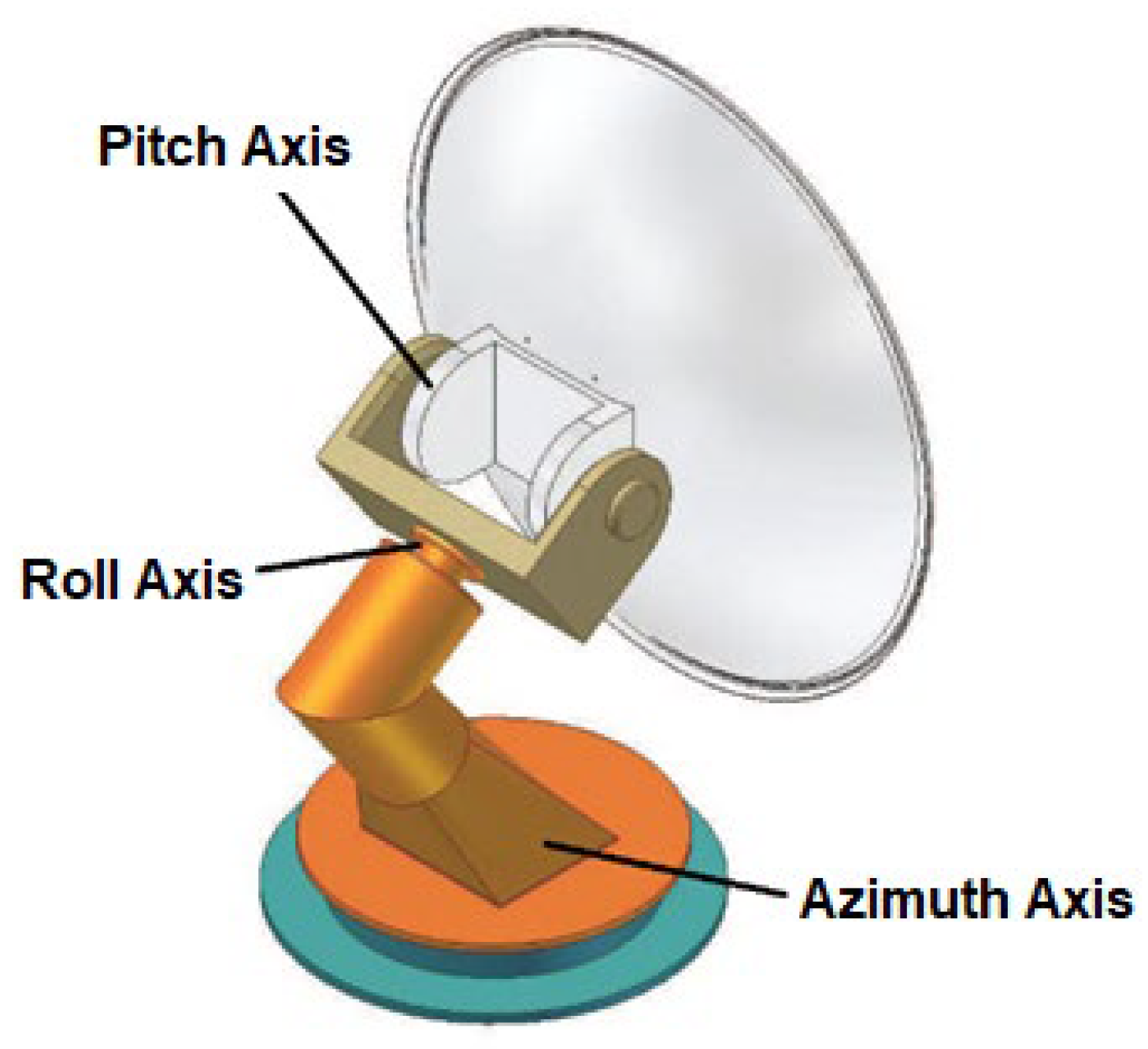
Figure 1. A common three-axis SOTM mechanical structure.
Aerospace 11 00659 g001
Figure 2. A SATPRO three-axis SOTM system.
Aerospace 11 00659 g002
Figure 3. Coordinate system configuration.
Aerospace 11 00659 g003
Figure 4. Example of piecewise linearization method for sine function.
Aerospace 11 00659 g004
Figure 5. Indirect closed-loop control structure diagram.
Aerospace 11 00659 g005
Figure 6. Direct closed-loop control structure diagram.
Aerospace 11 00659 g006
Figure 7. ADRC structure diagram.
Aerospace 11 00659 g007
Figure 8. The traditional f a l function and the modified f a l function curve.
Aerospace 11 00659 g008
Figure 9. Experimental site.
Aerospace 11 00659 g009
Figure 10. The antenna’s azimuth for indirect and direct closed-loop structure with PID.
Aerospace 11 00659 g010
Figure 11. The antenna’s pitch for indirect and direct closed-loop structure with PID.
Aerospace 11 00659 g011
Figure 12. The RTAGCL of SOTM for the indirect and direct closed-loop structure with PID.
Aerospace 11 00659 g012
Figure 13. The RTSNR of SOTM for the indirect and direct closed-loop structure with PID.
Aerospace 11 00659 g013
Figure 14. The RTSQ of SOTM for the indirect and direct closed-loop structure with PID.
Aerospace 11 00659 g014
Figure 15. The antenna’s azimuth for the indirect closed loop with PID and direct closed loop with the ADRC.
Aerospace 11 00659 g015
Figure 16. The antenna’s pitch for the indirect closed loop with PID and direct closed loop with the ADRC.
Aerospace 11 00659 g016
Figure 17. The SOTM’s RTAGCL for the indirect closed loop with PID and direct closed loop with the ADRC.
Aerospace 11 00659 g017
Figure 18. The SOTM’s RTSNR for the indirect closed loop with PID and direct closed loop with the ADRC.
Aerospace 11 00659 g018
Figure 19. The SOTM’s RTSQ for the indirect closed loop with PID and direct closed loop with the ADRC.
Aerospace 11 00659 g019
Table 1. The DH table of the kinematic model in Figure 3.
i α i 1 a i 1 d i θ i
1 0 0 0 θ 1
2 π 0 l 1 0
3 π / 2 + β 0 0 π / 2
4 π l 2 sin β l 2 cos β θ 2 + π
5 π 0 l 3 0
6 π / 2 0 0 θ 3
Table 2. The statistical characteristics of antenna pointing throughout the whole experiment.
Indirect Closed-LoopDirect Closed-Loop
AzimuthPitchAzimuthPitch
Max Value141.8943.31141.8143.09
Min Value140.7242.46140.8842.53
Mean Value141.3542.85141.3342.80
Range1.170.850.930.56
Variance5.53 × 10−22.916 × 10−23.58 × 10−21.992 × 10⁻²
Table 3. Statistical characteristics related to system communication throughout the whole experiment.
Indirect Closed-LoopDirect Closed-Loop
RTAGCLRTSNRRTSQRTAGCLRTSNRRTSQ
Mean Value2.16412.3296.702.17212.4797.27
Variance1.81 × 10−51.77 × 10−23.851.45 × 10−51.59 × 10−22.66
Table 4. The statistical characteristics of antenna pointing throughout the whole experiment with the introduction of the improved ADRC in the direct closed-loop control.
AzimuthPitch
Max Value141.6643.07
Min Value141.0242.55
Mean Value141.3642.80
Range0.640.52
Variance2.24 × 10−21.90 × 10⁻²
Table 5. Statistical characteristics related to system communication throughout the whole experiment with the introduction of the improved ADRC in the direct closed-loop control.
RTAGCLRTSNRRTSQ
Mean Value2.19012.5897.48
Variance9.83 × 10−61.16 × 10−22.21
Disclaimer/Publisher’s Note: The statements, opinions and data contained in all publications are solely those of the individual author(s) and contributor(s) and not of MDPI and/or the editor(s). MDPI and/or the editor(s) disclaim responsibility for any injury to people or property resulting from any ideas, methods, instructions or products referred to in the content.