Abstract
For special tail sitter configurations such as the ducted fan tail sitter unmanned aerial vehicle (UAV), the widely used trajectory planning methodology based on differential flatness might not be applicable due to complex aerodynamic coupling effects. As a result, the flight mode transition remains a challenging task. In this paper, we address the time optimal altitude-hold flight mode transition issue for a class of ducted fan tail sitter UAV. The foundation of the framework is the dynamic transition corridor in which the limitation of jerk is particularly considered, aiming to thoroughly reflect the dynamic feature of aggressive maneuvers. Based on this, we propose a time optimal strategy to generate feasible altitude-hold transition trajectories. Simultaneous, by fully utilizing the manifestation of time optimal altitude-hold flight behavior revealed by the transition corridor, we try to tackle the time optimal altitude-hold transition by means of a novel model-free control scheme. Comparative simulations show that both of the transition strategies achieve satisfactory performance on time optimal altitude-hold transition in the absence of disturbance, while the model-free control scheme exhibits better robustness under external disturbance.
1. Introduction
The tail sitter unmanned aerial vehicle (UAV) is characterized by both efficient high-speed flight and the capability of vertical take-off and landing (VTOL), receiving growing research interest within the UAV community over recent decades. Compared with other VTOL configurations, such as the tilt-rotor, the tail sitter configuration has a significant advantage in reliability and portability, since the transition between vertical flight and level flight is conducted simply through tilting the entire body. This makes tail sitter UAVs promising in various military and civil scenarios, such as long-range missions requiring fast vehicular launching and recycling [1].
Reliable autonomous flight mode transition control is essential for a tail sitter UAV, and it remains a challenge in the UAV control field. During the forward transition from vertical flight to level flight, or the backward transition from level flight to vertical flight, a tail sitter is subjected to significant aerodynamic changes, leading to a complex high-order system dynamics with extreme nonlinearity. In the earlier studies on tail sitter control, researchers tried to simplify the transition dynamic model by adopting transition trajectories in which the angle of attack (AoA) remains small, such that the wing aerodynamics remain linear [2,3,4,5,6]. A typical one is the PX4 built-in trajectory, providing a linear pitch angle command and constant thrust value [7]. However, these approaches always result in transition trajectories with an inevitable increase in altitude. In scenarios in which a tail sitter is to perform a rapid transition with rather small altitude change or exhibit other aggressive aerobatic maneuvers, the above traditional methods might not work well since they are constructed based on reduced models that fail to capture the complexity of real-world situations [8]. As a matter of fact, tail sitter UAVs are capable of performing aggressive flights within a large flight envelope, whereas the corresponding control techniques are still underdeveloped. The challenge still lies in the complicated nonlinear aerodynamics of the maneuvering process, involving significant variation in AoA. Smeur et al. propose a full envelope controller for a tail sitter based on incremental nonlinear dynamic inversion (INDI) to reduce the reliance on an accurate aerodynamic model [9]. Tal el al. also utilize the INDI technique integrated with -theory and differential flatness to perform accurate aerobatic flights [10,11,12]. Lu et al. develop a comprehensive control methodology for tail sitter aggressive flights based on full knowledge of the wing aerodynamics, in which an elaborate differential flatness model is derived for efficient online trajectory planning [13]. Nevertheless, these methods are only applicable to some specific tail sitter configurations, such as the quadrotor tail sitter. For tail sitters with more intricate aerodynamic designs, a more general methodology is still in demand.
This paper studies a novel tail sitter UAV configured with a single ducted fan propulsion system. A ducted fan propulsion system is a shrouded fan installed with outlet control vanes, which provides the desired thrust by controlling the fan rotational speed and provides the desired attitude control moment by deflecting those control vanes. Compared with a traditional tail sitter with open propellers, a ducted fan tail sitter exhibits greater controllability and maneuverability due to the fact that the thrust and control moment from the ducted fan remain relatively independent regardless of the flight regime and exogenous wind gust [14]. However, due to the complex coupling effects inherent in its aerodynamics, finding a proper resolution for the differential flatness of a ducted fan tail sitter is challenging. As a result, the widely used differential-flatness-based trajectory generation methods, such as [12,13], are not available.
Instead of establishing a sophisticated differentially flat model, we could consider an alternative methodology—the transition corridor. A transition corridor investigates the relationship between some determinant variables during a transition process, e.g., the airspeed-AoA corridor. By establishing the constraints of relevant system states according to the identified transition corridor, a nonlinear transition trajectory planning problem governed by complicated aerodynamic effect can be transformed to a normal constrained optimization problem. This could dramatically release the computational burden for online transition trajectory planning. The concept of a transition corridor was originally developed from the investigation of transition flight equilibrium [15,16,17,18,19]. These studies provide clear insights into the characteristics of how the trim condition varies during the transition. However, the trim condition could not thoroughly reflect the dynamic feature for a transition process, especially for an aggressive transitional maneuver with large acceleration/deceleration. In this case, it is necessary to extend the equilibrium transition corridor to a dynamic one, in which higher-order dynamics should be considered. Based on a small dual-rotor tail sitter UAV, Zhong et al. show that the static and dynamic characteristics are quite different [20]. Yang et al. conduct an elaborate analysis on the dynamic transition corridor of a similar tail sitter prototype and investigate how aerodynamic uncertainty could affect the corridor bounds. They also propose a transition trajectory planning strategy based on a dynamic transition corridor, which has been successfully validated through practical flight tests [21].
The advantage of a transition corridor is that once it has been identified, we could transform the trajectory generation problem based on a complex aircraft model into a simple motion planning problem with constraints by the corridor. In terms of trajectory planning, we just have to execute a one-round offline computation on the transition corridor and no longer need to solve the optimization problem with respect to the complex aircraft system in every time step. This could dramatically release the online computation burden. However, the existing transition-corridor-based studies only try to plan the fight trajectory in the middle of the corridor, considering that the corridor bounds might be sensitive to aerodynamic uncertainties and disturbance. So far, the corridor-based methodology has not been applied on fast transitions due to the fact that the resulting trajectories might be very close to the corridor bounds.
In this paper, based on the aforementioned ducted fan tail sitter UAV platform, we focus on the autonomous control of a special super-maneuver called the altitude-hold transition, in which the aircraft accomplishes the flight mode transition process with unchanged altitude. It is of great application potential to study the altitude-hold transition because it enables a tail sitter UAV to operate in a more cluttered environment [22]. As pointed out in [23,24], the challenge of altitude-hold transition is that the transition trajectory, which should be strictly confined to the corresponding transition corridor, could not be arbitrarily chosen. Furthermore, it is also important to shorten the transition period in order to decrease the accumulation of altitude tracking error. Therefore, a time optimal transition strategy is taken into account. To fulfill a time optimal altitude-hold transition, we first build an elaborate dynamic model of the ducted fan tail sitter UAV with a thorough investigation of the wing and ducted fan aerodynamics. Subsequently, the transition corridor with respect to the altitude-hold transition is computed, based on which a transition trajectory generation strategy is proposed. We particularly demonstrate the manifestation of time optimal flight behavior in the transition corridor and propose a model-free control scheme to achieve time optimal transitional flights. The main contributions are summarized as follows:
- We first present a specific computation and analysis of the transition corridor with respect to the altitude-hold transition of a ducted fan tail sitter UAV. In order to accommodate aggressive maneuvers, the conventional dynamic transition corridor is extended to a higher-order one by considering the limitation of jerk.
- Based on the transition corridor, we propose an efficient strategy to generate a time optimal altitude-hold transition trajectory and adopt the existing full envelope controller [24] to track this trajectory. Simultaneously, a model-free control scheme is proposed to achieve the time optimal altitude-hold transitional flight without solving an optimization problem.
- Comparative simulations are conducted, showing that the proposed corridor-based model-free control scheme exhibits superior performance in the presence of disturbance.
The rest of this paper is organized as follows. Section 2 presents the system modeling of SHC09. Section 3 elaborates the formulation and results of the transition corridor with respect to the altitude-hold transition. Section 4 presents a time optimal altitude-hold transition generation method based on the transition corridor as well as a model-free time optimal altitude-hold transition control scheme. Section 5 exhibits the comparative simulation results and Section 6 draws conclusions.
2. System Modeling
As shown in Figure 1, the ducted fan tail sitter, designated as “SHC09”, comprises one ducted fan propulsion system and a front wing. Contrasted with the “V-bat-liked” configurations [3,14,24], the wings of SHC09 are rather small in order to acquire excellent agility. Due to the fact that the duct can provide considerable lift when operating at a level flight regime [25], the wing is designed to generate part of the lift and, most importantly, balance the pitch down moment from the ducted fan. Consequently, the center of gravity (CG) is strategically positioned between the front wing and the duct in order to ensure a consistently small resultant aerodynamic pitch moment throughout the entire flight envelope. The driven moments of roll, pitch, and yaw are generated through deflecting the six control vanes installed at the outlet of the duct.

Figure 1.
The “SHC09” ducted fan tail sitter UAV and illustration of the altitude-hold transition.
In this section, we present the system modeling of SHC09, including a complete dynamic modeling in the 3D space, an aerodynamic modeling of the wing and the ducted fan, and a reduced 2D model in the pitch plane, which is used for transition corridor computation.
2.1. 6-DOF System Dynamics
Definitions of the SHC09 are depicted in Figure 2. We adopt the conventional six-degree-of-freedom (DOF) modeling procedure to formulate the dynamics of the UAV. Superscripts and are utilized to specify whether a variable is formulated in the inertial frame or the body frame. Based on this, the inertial frame axes are denoted as and the body frame as . The position in the inertial frame, velocity in the inertial frame, the Euler angles, the rotation matrix from the body frame to the inertial frame, and the angular velocity in the body frame are denoted as , , , , , respectively. SO(3) represents the special orthogonal group for which . Specifically, 0° of roll and pitch is defined according to the vertical flight regime. According to the Newton–Euler equations, the 6-DOF dynamics of the aircraft are modeled as:
where m is the total mass and is the inertia matrix. The map is defined by . are the gravity-excluded resultant force and moment in the body frame, respectively, which will be discussed later.
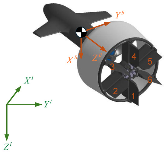
Figure 2.
Definitions of reference frames.
2.2. Aerodynamics
Previously, we have used to denote the environmental wind speed in the inertial frame. Then, the airspeed vector can be defined as:
Some relevant variables are defined by:
where V denotes the scalar airspeed value, denotes the AoA, denotes the slide-slip angle, and denotes the local AoA of the duct.
In (1), the resultant force is composed of the aerodynamic force of the wing and body , the normal force of the duct , and the thrust T. And the resultant moment is composed of the aerodynamic moment of the wing and body , the pitch moment of the duct , the gyroscopic moment of the fan , and the driven moment .
Note that the fan torque is not included in (4) as it is counteracted by the stators, which generate an anti-torque effect, while yaw control is beyond the scope of this paper.
As the control inputs of a practical ducted fan UAV system, denotes the fan rotational speed, and denotes the vane deflection, where denotes the deflection angle of the control vane. Subsequently, by referring to [24], the aerodynamic terms in (4) are given as the following parameterized form:
and
where are constant coefficients related to the aerodynamic feature of the ducted fan tail sitter.
2.3. Planar Dynamics
The flight mode transition is mostly exhibited on the longitudinal plane corresponding to a pitch motion, while the roll and yaw angular rates are assumed to be zero. Based on this assumption, we can decouple the planar dynamics from the 6-DOF model (1). First, define the horizontal velocity as:
This planar model will be used to formulate and compute the transition corridor in the next section.
3. The Transition Corridor of Altitude-Hold Transition
In this section, we present the formulation and results of the transition corridor with respect to the altitude-hold transition of the ducted fan tail sitter UAV. In order to accommodate the aforementioned time optimal altitude-hold transition, which is a special type of aggressive maneuver, the conventional dynamic transition corridor is extended to a higher-order one by considering the limitation of jerk.
3.1. Transition Corridor Formulation
Basically, an altitude-hold transition requires that the altitude remain unchanged during the process. To achieve this condition, the vertical velocity and its derivatives must remain zero, leading to the following constraints:
As the vertical motion is being restricted, an altitude-hold transition is thereby reflected into horizontal motion. Therefore, the determinant variables are reduced to , which is equivalent to . In this paper, the transition corridor is defined as the region containing all the admissible during an altitude-hold transition. To solve the complete transition corridor, we still need to consider the following boundary conditions:
Firstly, in the context of the transition corridor, the dynamics of angular rate is conventionally neglected. In other words, we always assume that the dynamics of angular rate (a low-level dynamics) is a highly fast manifold such that a desired angular rate can be instantaneously achieved in the time scale of higher-level dynamics (the dynamics of velocity). This assumption is rational and valid even in studies of some aggressive aerobatic control [12,13]. Consequently, the following quasi-static condition is considered:
Secondly, the input and state margins are also crucial to determine the corridor boundaries:
where is the limit of control vane defection. are the lowest and highest fan rotational speeds. is the maximum angular rate.
Finally, we consider the following initial and terminal conditions:
where is the cruising speed at level flight regime of the UAV, which is taken as the terminal speed of the forward transition or the initial speed of the backward transition.
3.2. Transition Equilibrium
The transition equilibrium is obtained from (10) with constraints (11) and (12) and , which establishes a baseline for transition analysis and controller design. For the sake of clearance, we use the following nondimensionalized terms to present the behavior of control inputs of the UAV system.
In (14), the collective behavior for pitch control from the second, third, fifth, and sixth vanes is represented by one single input variable , whose limits correspond to . And, the highest fan rotational speed is thereby formed as , while the fan rotational speed when hovering is around .
The results of the transition equilibrium are shown in Figure 3, revealing some interesting characteristics of SHC09. In Figure 3a, the trim pitch angle exhibits a continuous downward trend as the flight speed increases. In Figure 3b, the trim control vane deflection is less than 0.5 (), providing sufficient margin for maneuvering control. Moreover, as shown in Figure 3c, since corresponds to the power rate, it is obvious that an economical level flight speed should lie in . In this paper, the cruising speed is chosen as m/s.
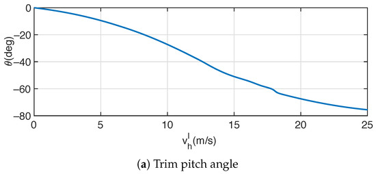
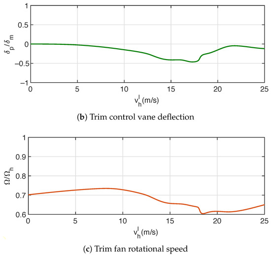
Figure 3.
Transition equilibrium.
3.3. Dynamic Transition Corridor
Results of the complete dynamic transition corridor are presented in Figure 4, in which the transition equilibrium in Figure 3 is depicted by the dashed curves. In Figure 4a, the upper part above the equilibrium () represents the transition corridor with respect to the forward transition, while the lower part represents the backward transition. Conversely, in Figure 4b, the situation is reversed due to the inverse relationship between positive acceleration and negative pitch angle according to their respective definitions.
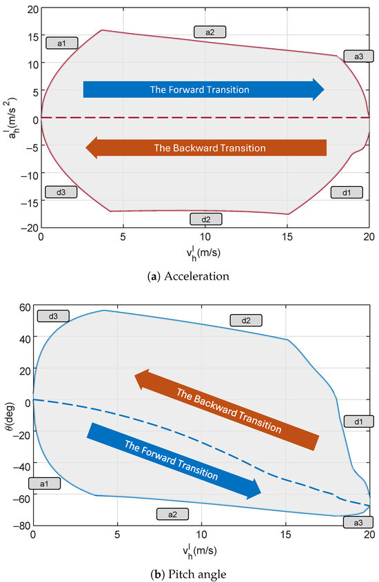
Figure 4.
Dynamic transition corridor (dashed curves: transition equilibrium).
During the forward transition, the UAV continuously accelerates from hovering to cruising. It is intuitive that the maximum acceleration is reached through tilting down the body to a proper pitch angle and setting the fan rotational speed to its highest. In this case, governed by the highest fan rotational speed (), the maximum admissible acceleration establishes the upper bound of the corresponding transition corridor in Figure 4a as well as the corresponding lower bound for pitch angle in Figure 4b, referred to as “a2”. It is seen that the global maximum acceleration, , is achieved at m/s by pitching down to with . However, the dynamics of is typically significant, especially for aggressive maneuvers. In other words, it is impractical to expect instantaneous achievement for a desired acceleration. Since we select the initial condition as , there should be a period in which the acceleration gradually increases from zero to its local maximum, which leads to another bound connecting the initial condition with the bound “a2”, referred to as “a1”. The determination of bound “a1” takes into account the maximum jerk, which is mainly governed by the maximum admissible angular rate, determined by (8) and (13). Similarly, bound “a3” is established by connecting bound “a2” with the terminal condition, indicating a braking behavior from acceleration to steady cruising flight.
During the backward transition, large deceleration is generally achieved through either the aerodynamic drag or reversed thrust, which depends on the configuration designs of the UAV platform. As revealed in Figure 4, the SHC09 platform reaches its maximum deceleration through the latter approach, i.e., a rapid pitching up of the maximum fan rotational speed, during which the thrust points in direction opposite to the flight speed. The corresponding deceleration bound is referred to as “d2”. It is seen that the global maximum deceleration, , is achieved at m/s by pitching up to with . This is a rather extreme flight regime, in which the vehicle operates at a backward pitch angle under a relatively high flight speed. Fortunately, the proposed dynamic transition corridor ensures that this status is reachable. Similar to the case of the forward transition, bounds “d1” and “d3” are introduced to connect the initial and terminal conditions with the bound “d2”.
In the context of jerk, the introduction of bounds “a1”, “a3”, “d1”, and “d3” guarantees the generation of dynamic feasible transition trajectories from the initial condition to the terminal condition. However, It is not preferred to directly utilize the transition corridor in Figure 4 since the corridor bounds are piecewise. Moreover, those bounds might not be highly reliable due to aerodynamic uncertainty and external wind disturbance. Furthermore, it is worth pointing out that the transition corridor in Figure 4 is formed by a set of isolated computational points. Therefore, it becomes essential to parameterize the transition corridor, specifically the corridor bounds, into compact expressions. Firstly, taking into account the influence from aerodynamic uncertainty, external wind disturbance, and fitting error, the corridor bounds in Figure 4 are scaled by 0.9. Then, we use the following numerical functions to parameterize these modified bounds.
where denotes an n-degree polynomial in the indeterminate , and . The curve fitting results are demonstrated in Figure 5, given as:
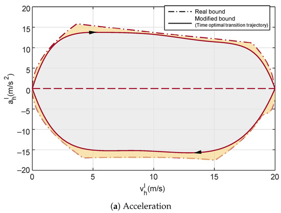
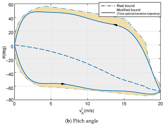
Figure 5.
Modified transition corridor.
Forward transition:
Backward transition:
Consequently, the transition corridor can be constructed as:
4. Time Optimal Altitude-Hold Transition Strategy
In this section, time optimal altitude-hold transition strategies are proposed based on the transition corridor (21) above. It is crucial to consider the optimization of time for an altitude-hold transition, as it significantly reduces the accumulation of altitude tracking error, which is typically systematic during aggressive maneuvers. In terms of the time optimal altitude-hold transition, we first adhere to the convention of addressing a trajectory generation and tracking problem. Then, we propose a model-free time optimal altitude-hold transition strategy by leveraging the revealed feature from the transition corridor.
4.1. Time Optimal Trajectory Generation
Basically, a successful altitude-hold transition requires that the transition trajectory be generated within the transition corridor (21). Based on this, a time optimal transition trajectory can be obtained by solving the following optimization problem:
Forward transition:
Backward transition:
The generated transition trajectories are denoted as . The corresponding trajectories of pitch angle and thrust are denoted as , which can be resolved from by (10). For low-level controller design, we follow the existing full envelop control scheme in [24] to track , which will not be discussed in this paper.
4.2. Model-Free Time Optimal Altitude-Hold Transition Design
A time optimal transition trajectory means that the flight speed always shifts at its largest gradient, which leads to the fact that the above time optimal trajectories coincide precisely with the transition bounds (21). As shown in Figure 4, an interesting characteristic revealed from the transition corridor is that the maximum admissible acceleration, which is the transition bounds in Figure 4a, corresponds to some certain input boundaries in (13). Specifically, taking the forward transition as an example, the aircraft first conducts a fast pitch down and gradually increases the fan rotational speed to its maximum, demonstrated by bound “a1”. In this stage, the angular rate q, or equivalently the jerk, is consistently at its largest such that the altitude-hold transition reduces to an one degree control problem, in which the thrust functions as the only control input to stabilize the altitude with an increasing trend. Once it reaches the maximum thrust, the transition process switches from bound “a1” to bound “a2”. In this subsequent stage, the aircraft maintains the highest fan rotational speed () to acquire the largest thrust, and the control input for the one-degree altitude-hold control problem switches from the thrust to the pitch angle or the pitch angular rate. In the final stage indicated by bound “a3”, the thrust decreases to the cruising equilibrium, while the angular rate switches to its inverse largest to perform a brake on the horizontal acceleration.
As mentioned above, the angular rate can be achieved with a rather fast dynamics, so we consider it as control input to the higher-level sub-system. In this part, the model-free control scheme is devised based on the following reduced dynamic model by (10):
Since can be measured by an onboard IMU, we can replace it with a specific force term, defined as . Therefore, (24) can be rewritten as:
where are regarded as the control inputs to the reduced system. Meanwhile, in the controller design, the desired control inputs are denoted as , and we assume that always holds, which will be discussed later. The model-free control scheme is presented as follows:
- (1)
- The forward transition
In the proposed model-free control scheme, the forward transition is conducted under three connected stages. In stage 1, the angular rate is set to its negative maximum value and the thrust serves to stabilize the altitude.
Stage 1:
where is the desired vertical velocity and is a positive feedback gain.
From (5), (8), and (26), it is obvious that increases as the flight speed increases, leading to a rising trend for . When reaching the maximum actual fan rotational speed (), we switch to stage 2. In stage 2, the fan rotational speed maintains and the angular rate is alternated to stabilize the altitude.
Stage 2:
where is a positive feedback gain.
The final stage is supposed to be a mirroring process of stage 1, in which and follows (26). However, unlike the switch between stage 1 and stage 2, it is not easy to find the proper switching condition from stage 2 to stage 3. Intuitively, we should find a velocity threshold which precisely results in the terminal condition through . To this end, some sophisticated prediction and re-planning techniques are to be employed, considering the fact that the system model is highly coupled with external wind disturbance, such as the model predictive control in [26]. Unfortunately, this will make the controller design too complicated, which is not preferred in our model-free control scheme. Instead, we consider stage 3 as a simple stabilization problem towards the terminal condition . According to the transition corridor in Figure 4, it is evident that the aircraft operates at a level flight regime at bound “a3”, so the control policy in stage 3 is established as a nonlinear level flight controller.
Stage 3:
where are positive feedback gains.
The switching condition from stage 2 to stage 3 is determined as m/s. Since stage 3 does not match bound “a3”, the final stage might not be strictly time optimal. Note that, as apparently revealed in Figure 4, the time period during stage 3 appears to be very short since the flight speed already approaches . Although there might only be a slight difference between a rigorous time optimal transition resulting from (22) and the stage 3 design in (28), the latter could lead to better robustness in the presence of external wind disturbance. This will be verified in the next section.
- (2)
- The backward transition
Due to the symmetric feature of the transition corridor, the backward transition is also conducted under three connected stages. In stage 1, the angular rate is set to its positive maximum value , reflecting a pitch up motion, and the thrust serves to stabilize the altitude similar to that in the forward transition design.
Stage 1:
Similarly, once reaching , it switches to stage 2.
Stage 2:
Subsequently, once decelerated to m/s, it switches to stage 3 with the following geometric controller for vertical flight.
Stage 3:
- (3)
- Thrust compensation control
The above model-free control scheme is based on the assumption that . For a desired , it is possible to algebraically resolve the proper from the complex aerodynamic models (5) and (8) in order that . However, this approach might not always be reliable due to model uncertainty and external disturbance. Instead, we design the following thrust compensator:
where are positive gains. is a feedforward term building a primary approximation of , while functions to compensate the error between the desired and the real resultant force . This can be easily verified by considering the following Lyapunov function:
4.3. Discussion
In convention, the trajectory generation and tracking issues are separately addressed. The advantage of the transition corridor lies in its ability to map all the aerodynamic complexity and system constraints into the corridor bounds, thereby transforming the transition optimization problem into the normal nonlinear programming form like (22) and (23), which is much easier to solve. Additionally, it takes into account the feasibility of the generated trajectory such that the system constraints can be hidden in the tracking controller design. However, this methodology remains highly model-based, as uncertainties and external disturbance can still affect the transition performance. On the contrary, the proposed model-free control scheme requires only a rough selection of in (32). The time optimality, or rigorously near-time optimality, is guaranteed by the transition corridor, which qualitatively exhibits the inherent characteristics of time optimal transition behavior. In other words, in our model-free control design, the transition corridor only assists in determining which boundary condition should be followed to accomplish a time optimal altitude-hold transition. Therefore, it is obvious that the proposed model-free control scheme has excellent robustness to model uncertainty and external disturbance. This will be further verified in the next section.
5. Simulations
In this section, we present the simulation results to validate the proposed methods through comparisons between the conventional trajectory generation and tracking approach in Section 4.1 and the model-free control scheme in Section 4.2, which will be referred to as “conventional method” and “MFC”, respectively. In particular, we design the following transition courses to exhibit the performance of the two methods. For the forward transition, the aircraft is initialized hovering and keeps hovering for 1 s. Then, it conducts a forward transition to level flight, and ends up with a steady cruising flight at . For the backward transition, the aircraft is initialized at cruising level flight and holds for 2 s. Then, it conducts a backward transition to . Once the horizontal velocity and acceleration decrease to zero, the aircraft marks the local position as reference and switches to hovering. The altitude is set to m and we utilize the following position feedback loop for altitude stabilization during the entire flight course and position control during hovering:
In this paper, two simulations are conducted to compare the conventional method and the MFC in executing the above flight course, with simulation 1 being disturbance-free and simulation 2 involving wind disturbances. It is expected that both methods should perform similarly in the absence of disturbance, whereas the MFC will perform better in confronting external wind disturbance. Specifically, in the conventional method, we follow (22) and (23) to generate the time optimal altitude-hold transition trajectories and adopt the full envelope controller in [24] for hovering, transition trajectory tracking, and level flight control, while in the MFC, the time optimal control scheme is consistent with (26)–(32) for thrust compensation control and the INDI design in [24] for angular rate control. Simulations are built in MATLABTM.
5.1. Simulation 1
Results of the forward transition in simulation 1 are depicted in Figure 6, in which the two forward transitions start at 1 s consistently. As indicated in Figure 6a, the transition period for the conventional method and the MFC are 2.2 s and 1.8 s, respectively. It is seen that the tracking performances of are close, whereas other behaviors are a bit different. In Figure 6a, compared with the MFC, there is an evident lag in the conventional method. This is mainly attributed to the tracking error between the generated trajectory and the real control performance in the conventional trajectory generation and tracking methodology, while under the MFC, the real performance is expected to precisely match the optimal trajectory. In Figure 6b, the altitude for the MFC descends during the forward transition with a maximum altitude tracking error of 0.3 m, while for the conventional method, the altitude demonstrates an ascending-to-descending trend, with a total maximum altitude change of 0.7 m, in which the maximum altitude tracking error is 0.3 m during ascent and 0.4 m during descent. Additionally, as exhibited in Figure 6c,d, the pitch down motion of the MFC is faster than that of the conventional method in the first 1.5 s because the model-free control scheme tries to reach the fastest pitch angular rate in stage 1, whereas the conventional trajectory generation and tracking approach inevitably results in tracking errors. This contributes to the discrepancy of the altitude-holding performances in Figure 6b.
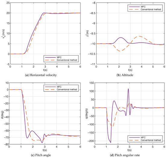
Figure 6.
Results of forward transition in simulation 1.
Results of the backward transition in simulation 1 are depicted in Figure 7. Similarly, the two backward transitions start at 2 s consistently. As indicated in Figure 7a, the transition period for the conventional method and the MFC are 2.2 s and 1.9 s, respectively. Similar to that, in the forward transition in Figure 6, the horizontal velocity of the conventional method exhibits an evident lag during the backward transition. In Figure 7b, in contrast with that in the forward transition in Figure 6b, the altitude for the MFC exhibits an ascending-to-descending trend with a total maximum altitude change of 0.49 m, in which the maximum altitude tracking error is 0.25 m during ascent and 0.24 m during descent. In the meanwhile, the altitude for the conventional method shows an ascending feature, with a maximum altitude tracking error of 0.53 m. Furthermore, as revealed in Figure 7c,d, both the conventional method and the MFC exhibit a rapid pitching up to flight regimes with backward pitch angles in order to achieve the time optimal backward transition. The pitch up motion of the MFC is also faster than that of the conventional method in the first 1.8 s, resulting in the fact that the altitude for the MFC sticks closer to the setting point.
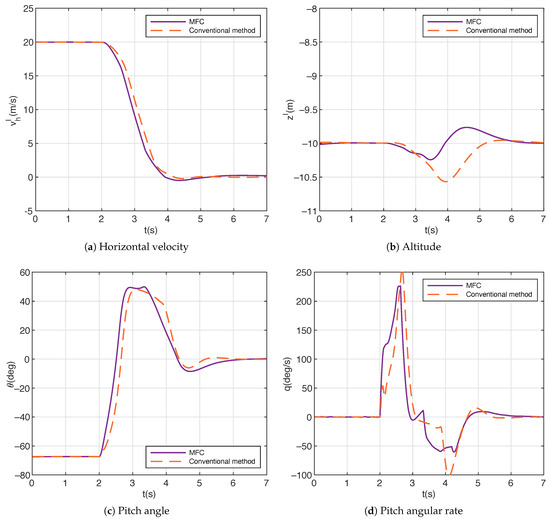
Figure 7.
Results of backward transition in simulation 1.
Collectively, Figure 6 and Figure 7 verify that both the conventional method and the MFC are effective in accomplishing the time optimal altitude-hold transition in the absence of disturbance, in which the performances on flight speed are similar and the altitude holding performances are satisfactory.
5.2. Simulation 2
In simulation 2, we conduct comparative simulations to demonstrate the performances of the two methods under external disturbance. Resembling the definition of horizontal velocity by (9) and referring to (4), we define the horizontal wind speed as:
As depicted in Figure 8, wind disturbances are introduced as:

Figure 8.
The introduction of wind disturbance in simulation 2.
Besides the introduction of disturbance, other conditions in simulation 2 are consistent with those in simulation 1.
Results of the forward transition in simulation 2 are depicted in Figure 9, in which the two forward transitions also start at 1s consistently. The time periods for wind disturbance are marked by the gray areas. As indicated in Figure 9a, the transition period for the conventional method and the MFC are 2.4 s and 1.85 s, respectively, increasing by 0.2 s and 0.05 s compared with the case without disturbance shown in Figure 6a. Under the disturbance defined by (39), it is seen that the acceleration of suffers a slowdown trend after 2.5 s compared with that in Figure 6a for the conventional method, while the results for the MFC are nearly the same with and without disturbance. The influence of disturbance is more significant on the altitude. In Figure 9b, the altitude for the MFC descends during the forward transition, with a maximum altitude tracking error of 0.35 m, which is a slight increase by 0.05 m compared with the disturbance-free case in Figure 6b. On the other hand, for the conventional method, the altitude also demonstrates an ascending-to-descending trend, with a total maximum altitude change of 1 m, in which the maximum altitude tracking error is 0.6 m during ascent and 0.4 m during descent. In this case, the altitude tracking error reaches its peak exactly during the disturbance period, increasing by 0.3 m compared with the disturbance-free case in Figure 6b. In Figure 9c,d, it is evident that the pitch angle for the MFC reacts quickly to adjust the altitude through pitching up, while the conventional method behaves more sluggishly.
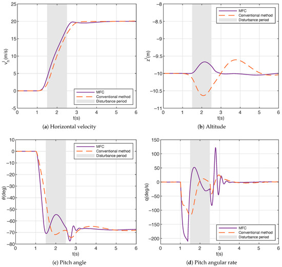
Figure 9.
Results of forward transition in simulation 2.
Results of the backward transition in simulation 2 are depicted in Figure 10, in which the two backward transitions also start at 2 s consistently. The same goes for Figure 9, in which the time periods for wind disturbance during the backward transition in simulation 2 are marked by the gray areas. As indicated in Figure 10a, the transition period for the conventional method and the MFC are 2.5 s and 2 s, respectively, increasing by 0.3 s and 0.1 s compared with the case without disturbance shown in Figure 7a. Similar to that in the forward transition in Figure 9a, the deceleration of suffers a more obvious slowdown trend after 2.5 s for the conventional method under disturbance. As for the altitude in Figure 10b, the maximum tracking errors for the MFC increase slightly to 0.4 m during ascent and 0.3 m during descent, compared with the disturbance-free case in Figure 7b. On the other hand, for the conventional method, the maximum altitude tracking error suffers a significant increase from 0.53 m (the disturbance-free case shown in Figure 7b) to 1.1 m. Unlike that in the forward transition in simulation 2, it can be seen in Figure 10b that the introduction of disturbance in the backward transition causes a considerable altitude ascending rate for the conventional method, whereas the conventional method fails to fix this ascending trend promptly and leads to an altitude tracking error peak by 11.1 m at 4.1 s (0.6 s after the end of the disturbance). Furthermore, as revealed in Figure 10a,b, the horizontal velocity for the conventional method shows an noticeable oscillation around 0 at , the period after the accomplishment of backward transition. This is due to fact that in this period, there exists a massive altitude deviation, and the altitude converging behavior by the conventional method eventually results in some coupling effect on the horizontal channel.
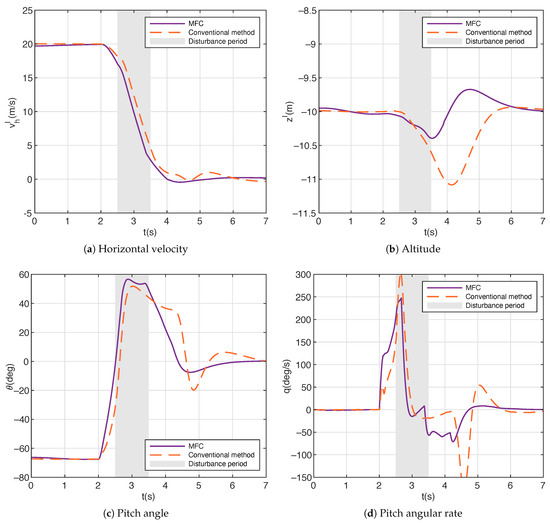
Figure 10.
Results of backward transition in simulation 2.
5.3. Simulation Conclusions
Apparently, the performances of the altitude-hold transition for the MFC are consistent with and without disturbance, since the model-free designs in (26)–(32) are of great robustness. On the other hand, for the conventional method, the introduction of disturbance leads to slight slowdown trends for both the acceleration and deceleration processes, whereas the altitude suffers significant deviation from the setting point. This is because the time optimal transition trajectories generated by (22) and (23) may no longer be feasible altitude-hold trajectories under the influence of disturbance. To maintain close tracking of the horizontal velocity, the controller has to sacrifice the performance of the altitude channel. This is an inherent defect for the conventional method. In all, these simulations collectively verify the advantage of the proposed model-free control scheme in accomplishing the time optimal altitude-hold transition.
6. Conclusions
In this paper, we have proposed time optimal altitude-hold flight mode transition strategies for a class of ducted fan tail sitter UAV. The foundation of the framework is the dynamic transition corridor in which the limitation of jerk is particularly considered, aiming to thoroughly reflect the dynamic feature of aggressive maneuvers. Based on this, we have proposed a time optimal strategy to generate feasible altitude-hold transition trajectories. A model-free control scheme is further proposed, fully utilizing the manifestation of time optimal altitude-hold flight behavior revealed by the transition corridor. Comparative simulations show that both transition strategies achieve satisfactory performance on the time optimal altitude-hold transition in the absence of disturbance, while the model-free control scheme exhibits better robustness under external disturbance.
The limitation of this work lies our neglect of the dynamics of fan rotational speed, which corresponds to the derivative of thrust and could affect the performance with respect to the time scale of jerk. In future work, we will consider this issue and implement the proposed transition strategies in practical flight tests.
Author Contributions
Conceptualization, H.P.; Methodology, Z.C.; Validation, Z.C.; Investigation, Z.C.; Writing and original draft, Z.C.; Writing, review and editing, H.P. All authors have read and agreed to the published version of the manuscript.
Funding
This study was supported by Aeronautical Science Foundation of China (20220056060001), Scientific Instruments Development Program of NSFC (61527810), New Generation of Information Technology Innovation Project, China University Innovation Fund (2022IT046), and the Fundamental Research Funds for the Central Universities.
Data Availability Statement
No new data were created.
Acknowledgments
The authors wish to thank the Key Laboratory of Autonomous Systems and Networked Control, Ministry of Education and the Guangdong Engineering Technology Research Center of Unmanned Aerial Vehicle Systems for supporting this research.
Conflicts of Interest
The authors declare no conflicts of interest.
References
- Ducard, G.J.J.; Allenspach, M. Review of designs and flight control techniques of hybrid and convertible VTOL UAVs. Aerosp. Sci. Technol. 2021, 118, 25. [Google Scholar] [CrossRef]
- Stone, R.H.; Anderson, P.; Hutchison, C.; Tsai, A.; Gibbens, P.; Wong, K.C. Flight testing of the T-wing tail-sitter unmanned air vehicle. J. Aircr. 2008, 45, 673–685. [Google Scholar] [CrossRef]
- Jung, Y.; Cho, S.; Shim, D.H. A Comprehensive Flight Control Design and Experiment of a Tail-Sitter UAV. In Proceedings of the AIAA Guidance, Navigation, and Control (GNC) Conference, Boston, MA, USA, 19–22 August 2013. [Google Scholar]
- Banazadeh, A.; Taymourtash, N. Optimal Control of an Aerial Tail Sitter in Transition Flight Phases. J. Aircr. 2016, 53, 914–921. [Google Scholar] [CrossRef]
- Oosedo, A.; Abiko, S.; Konno, A.; Uchiyama, M. Optimal transition from hovering to level-flight of a quadrotor tail-sitter UAV. Auton. Robot. 2017, 41, 1143–1159. [Google Scholar] [CrossRef]
- Yunjie, Y.; Jihong, Z.; Jiali, Y. INDI-Based Transitional Flight Control and Stability Analysis of a Tail-Sitter UAV. In Proceedings of the 2020 IEEE International Conference on Systems, Man, and Cybernetics, Toronto, ON, Canada, 11–14 October 2020; pp. 1420–1426. [Google Scholar]
- Li, B.Y.; Sun, J.X.; Zhou, W.F.; Wen, C.Y.; Low, K.H.; Chen, C.K. Transition Optimization for a VTOL Tail-Sitter UAV. IEEE-ASME Trans. Mechatronics 2020, 25, 2534–2545. [Google Scholar] [CrossRef]
- Xin, H.B.; Wang, Y.J.; Gao, X.Z.; Chen, Q.Y.; Zhu, B.J.; Wang, J.F.; Hou, Z.X. Modeling and control of a quadrotor tail-sitter unmanned aerial vehicles. Proc. Inst. Mech. Eng. Part I-J. Syst. Control Eng. 2022, 236, 443–457. [Google Scholar] [CrossRef]
- Smeur, E.J.J.; Bronz, M.; de Croon, G.C.H.E. Incremental Control and Guidance of Hybrid Aircraft Applied to a Tailsitter Unmanned Air Vehicle. J. Guid. Control Dyn. 2019, 43, 274–287. [Google Scholar] [CrossRef]
- Tal, E.; Karaman, S. Global Incremental Flight Control for Agile Maneuvering of a Tailsitter Flying Wing. J. Guid. Control Dyn. 2022, 45, 2332–2349. [Google Scholar] [CrossRef]
- Tal, E.; Karaman, S. Accurate Tracking of Aggressive Quadrotor Trajectories Using Incremental Nonlinear Dynamic Inversion and Differential Flatness. IEEE Trans. Control Syst. Technol. 2021, 29, 1203–1218. [Google Scholar] [CrossRef]
- Tal, E.; Ryou, G.; Karaman, S. Aerobatic Trajectory Generation for a VTOL Fixed-Wing Aircraft Using Differential Flatness. IEEE Trans. Robot. 2023, 39, 15. [Google Scholar] [CrossRef]
- Lu, G.Z.; Cai, Y.X.; Chen, N.; Kong, F.Z.; Ren, Y.F.; Zhang, F. Trajectory generation and tracking control for aggressive tail-sitter flights. Int. J. Robot. Res. 2023, 43, 40. [Google Scholar] [CrossRef]
- Fu, Y.B.; Zhao, W.J.; Liu, L. Safe Reinforcement Learning for Transition Control of Ducted-Fan UAVs. Drones 2023, 7, 332. [Google Scholar] [CrossRef]
- Saghafi, F.; Banazadeh, A. Investigation on the flight characteristics of a conceptual fluidic thrust-vectored aerial tail-sitter. Proc. Inst. Mech. Eng. Part G-J. Aerosp. Eng. 2007, 221, 741–755. [Google Scholar] [CrossRef]
- Zhao, W.; Underwood, C. Robust transition control of a Martian coaxial tiltrotor aerobot. Acta Astronaut. 2014, 99, 111–129. [Google Scholar] [CrossRef]
- Cakici, F.; Leblebicioglu, M.K. Design and analysis of a mode-switching micro unmanned aerial vehicle. Int. J. Micro Air Veh. 2016, 8, 221–229. [Google Scholar] [CrossRef]
- Dawkins, J.; DeVries, L. Modeling, Trim Analysis, and Trajectory Control of a Micro-Quadrotor with Wings. Drones 2018, 2, 21. [Google Scholar] [CrossRef]
- Tang, W.; Song, B.F. Transitional flight equilibrium and performance study for the X-NMRL tail-sitter VTOL MAV. Proc. Inst. Mech. Eng. Part G-J. Aerosp. Eng. 2019, 233, 3056–3077. [Google Scholar] [CrossRef]
- Zhong, J.Y.; Wang, C. Transition characteristics for a small tail-sitter unmanned aerial vehicle. Chin. J. Aeronaut. 2021, 34, 220–236. [Google Scholar] [CrossRef]
- Yang, Y.; Zhu, J.; Wang, X.; Yuan, X.; Zhang, X. Dynamic Transition Corridors and Control Strategy of a Rotor-Blown-Wing Tail-Sitter. J. Guid. Control Dyn. 2021, 44, 1836–1852. [Google Scholar] [CrossRef]
- Phillips, B.; Hrishikeshavan, V.; Chopra, I. Design, Development, and Testing of Package Delivery Quadrotor Biplane Tail-Sitter. J. Aircr. 2021, 58, 834–846. [Google Scholar] [CrossRef]
- Cheng, Z.H.; Pei, H.L. Transition Analysis and Practical Flight Control for Ducted Fan Fixed-Wing Aerial Robot: Level Path Flight Mode Transition. IEEE Robot. Autom. Lett. 2022, 7, 3106–3113. [Google Scholar] [CrossRef]
- Cheng, Z.H.; Pei, H.L. A corridor-based flight mode transition strategy for agile ducted-fan tail-sitter UAV: Altitude-hold transition. Chin. J. Aeronaut. 2023, 36, 330–345. [Google Scholar] [CrossRef]
- Zhang, T.; Barakos, G.N. Review on ducted fans for compound rotorcraft. Aeronaut. J. 2020, 124, 1–34. [Google Scholar] [CrossRef]
- Romero, A.; Sun, S.H.; Foehn, P.; Scaramuzza, D. Model Predictive Contouring Control for Time-Optimal Quadrotor Flight. IEEE Trans. Robot. 2022, 38, 3340–3356. [Google Scholar] [CrossRef]
Disclaimer/Publisher’s Note: The statements, opinions and data contained in all publications are solely those of the individual author(s) and contributor(s) and not of MDPI and/or the editor(s). MDPI and/or the editor(s) disclaim responsibility for any injury to people or property resulting from any ideas, methods, instructions or products referred to in the content. |
© 2024 by the authors. Licensee MDPI, Basel, Switzerland. This article is an open access article distributed under the terms and conditions of the Creative Commons Attribution (CC BY) license (https://creativecommons.org/licenses/by/4.0/).