1. Introduction
With the advancement of space technology, the next generation of space telescopes, high-resolution agile remote sensing, and gravitational wave detection missions impose higher demands on the attitude control performance of spacecraft [
1,
2,
3]. In order to further improve the attitude control performance of spacecraft, based on the design concept of dynamic and static isolation, our research team has proposed the new concept of non-contact annular electromagnetic stabilized spacecraft (NCAESS), which effectively mitigates the problems of dynamic coupling and nonlinear effects that occur in traditional designs of non-contact spacecraft [
4]. In previous studies, we have mainly focused on the influence of the control torque on the attitude of NCAESS. The precision of the torque is linearly related to the driving current of the non-contact annular electromagnetic actuator (NCAEA), the main actuator in NCAESS. In order to ensure the precision of the control torque and improve the control performance of NCAESS, the driving current control of NCAESS is investigated in this paper.
Through analysis, there are multiple disturbances in NCAESS, such as the current ripple that exists when switching power amplifiers are used [
5], the back electromotive force generated by the relative motion of the two modules during the NCAESS control process [
6], the time delay that exists when digital control is used [
7], the time-varying effect of the power amplifiers, and the influence of noise [
8]. In order to output precise driving current, it is necessary to use a suitable scheme to suppress the multiple disturbances and improve the robustness of the driving current control.
To address the current ripple problem in switching power amplifiers, traditional methods often involve increasing the switching frequency or using low-pass filters to reduce the magnitude of the current ripple [
9]. However, increasing the switching frequency also increases the switching losses of the power amplifier, and to achieve better ripple suppression, low-pass filters require larger values of components such as inductors, which may reduce the dynamic response performance of the power amplifier [
10]. J. Chen has introduced an improved active ripple eliminator to suppress the output current ripple of multi-phase buck converters. Experimental results demonstrate its effectiveness in attenuating ripple while preserving the fine-adjustment characteristics of the output voltage [
11]. M. Dasohari proposes a driver based on a soft-switching parallel boost converter, showing that the parallel boost converter can be adopted to reduce the current ripple and can be applied in both high- and low-power scenarios [
12]. Also, in terms of suppressing ripple by changing the switching frequency, Ref. [
13] proposes a variable-switching-frequency pulse-width modulation technique to improve the switching loss, current ripple, and electromagnetic interference performance of power amplifiers.
To solve the problem of back electromotive force disturbance, F. Chen proposes an adaptive controller based on an RBF neural network to control a magnetic-levitation stable platform with back electromotive force disturbance, thereby improving the anti-interference ability of the platform [
14]. J. Jeong analyzes the rotational motion error caused by the back electromotive force in magnetic-levitation systems and demonstrates that using a model-based feedforward compensation method can effectively suppress the rotational motion error induced by the back electromotive force [
15].
To solve the problem of time delay caused by digital control, compensators are commonly constructed to reduce the effect of the delay. Delay-compensating technology can be classified into model-based technology, such as the robust Smith predictor; model predictive controllers; model-free technology; and so on [
16]. J. Liu proposes an improved capacitor circuit by using multi-loop feedback current to mitigate the impact of delay on the network [
17]. However, this multi-loop method requires the measurement of multiple state variables, which increases the complexity of the controller and reduces the reliability. Ref. [
18] introduces a delay compensation method based on second-order generalized integrators to extend the stable region of a two-loop grid-current feedback control system. A. Katkout used a long-term prediction method to compensate the computational delays in multilevel inverter control loops [
19]. S. Karan used a robust Smith predictor to eliminate the delay terms in the unstable control systems [
20]. Through an analysis of the above literature, it is found that although model-free technology does not depend on the accuracy of the model, it struggles to fully compensate for the effects of time delays. Model-based technology is sensitive to the accuracy of system modeling. To better compensate for the effects of delay, the robust Smith predictor can be adopted to provide more advantages.
The actual control system is often affected by the combined influence of various forms of disturbances, which will reduce the stability and control effectiveness of the system. C. Jin proposes a composite layered disturbance-rejecting strategy, and combines an extended state observer, as well as the H
∞ controller, to improve the disturbance rejection capability of a magnetic-levitation rotor system with internal uncertainties and external disturbances [
21]. S. Chen proposes a composite-structure adaptive compensation technique to improve the pointing precision of a gyroscope with high-frequency tilting flutter and sensor noise effects [
22]. Ref. [
23] discusses a composite control strategy for a small-inductance brushless DC motor affected by disturbances in the commutation and conduction regions. This strategy combines a BUCK converter, overlapping commutation control, an optimized duty cycle, asymmetric compensation functions, back electromotive force feedforward compensation, and an improved disturbance torque controller to achieve precise acceleration torque control. J. Zou proposes a composite control strategy that combines fuzzy PID control with a recursive least-squares technique to improve the convergence speed of the current [
24]. Y. Liu proposes a composite control strategy that incorporates the robust Smith predictor, state observer compensation, and internal model nonlinear controllers to improve the tracking accuracy and positioning performance of a permanent-magnet synchronous-motor servo system affected by delays and external disturbances [
25]. Through an analysis of the above literature, it can be concluded that composite control strategies exhibit a better control performance than single algorithms in the face of multiple disturbances.
Inspired by the above idea, a composite control scheme is proposed in this paper to suppress multiple disturbances and thus ensure the control performance of NCAESS. The main contributions of this paper are summarized as follows:
- (1)
The proposed scheme suppresses the current ripple effectively without increasing the inductance value of the filter or adopting high switching frequencies. This preserves the dynamic response ability and reduces switching losses.
- (2)
The closed-loop control adopts the internal model principle and fuzzy rules to adjust the parameters adaptively, enhancing the robustness and dynamic response capability of the driving current effectively.
- (3)
The composite control algorithm can also suppress the disturbance effects caused by back electromotive force, time delay, time variance, and noise disturbance effectively, achieving precise control of the NCAESS.
The rest of this paper is organized as follows: In
Section 2, the NCAESS configuration, dynamic model, and driving current scheme adopted in this article are described. The composite controller design of the NCAESS is discussed in
Section 3. In
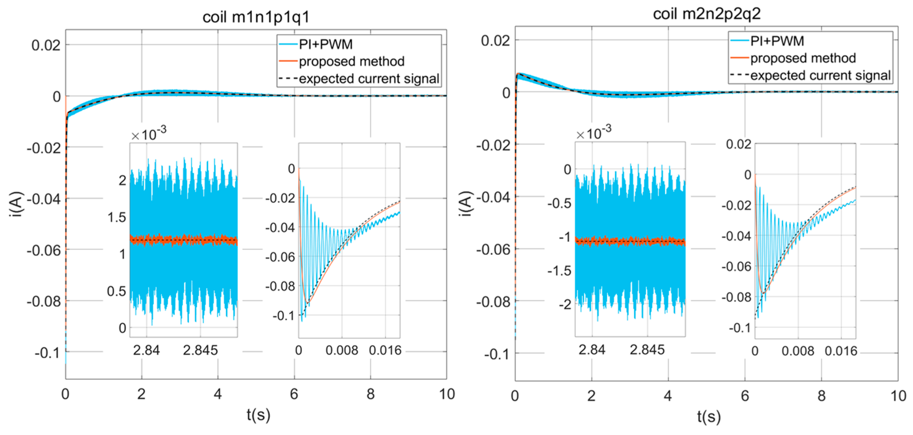
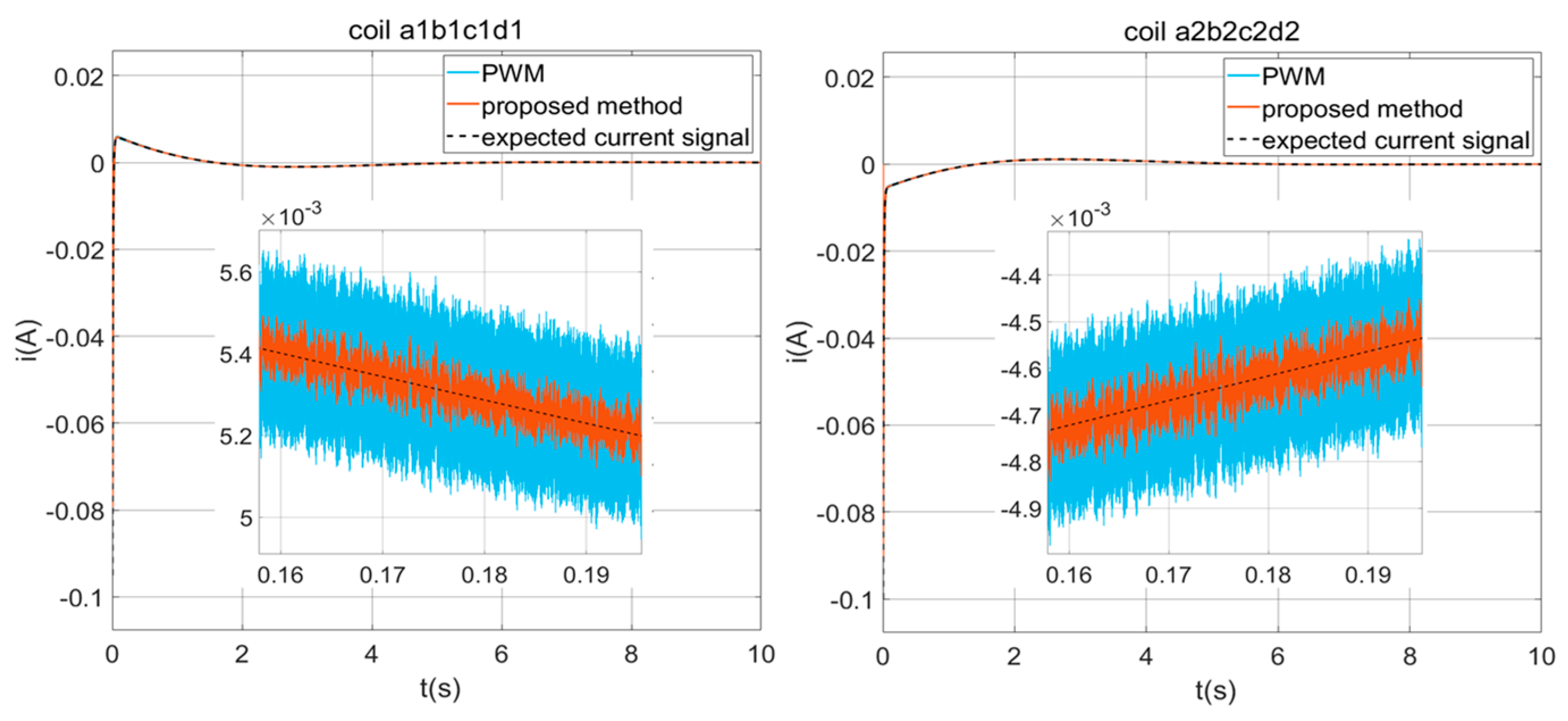
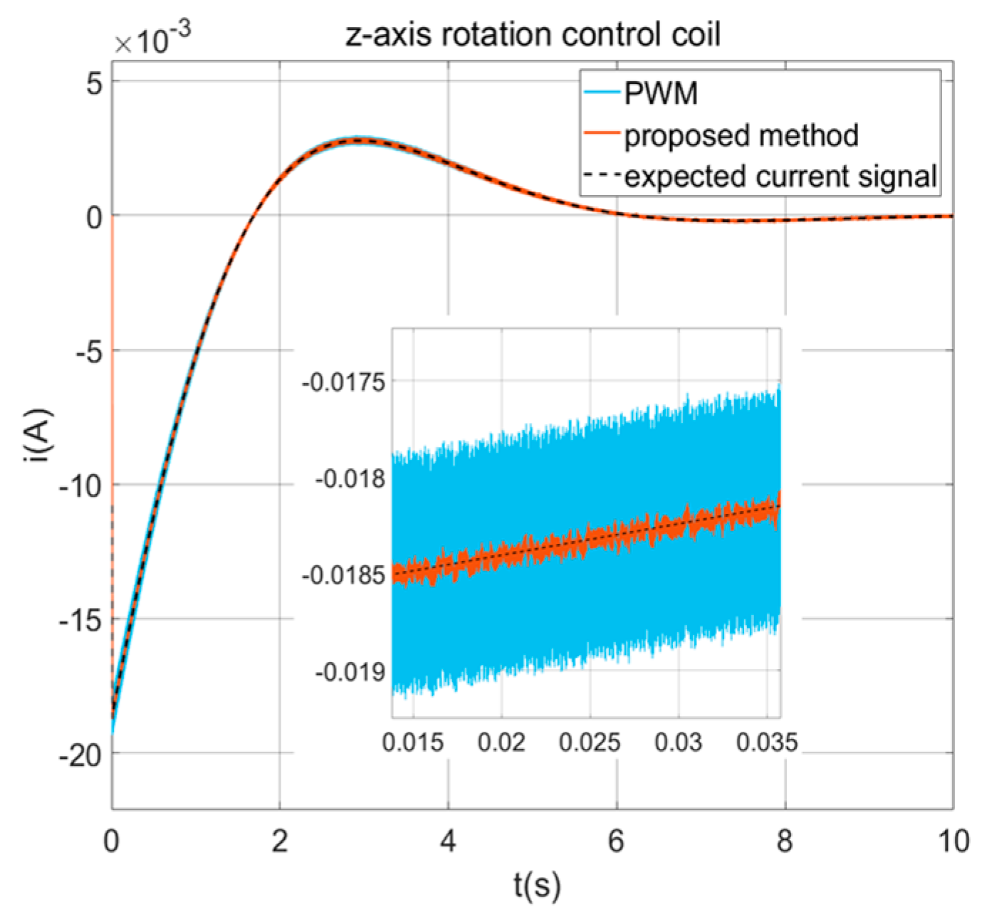
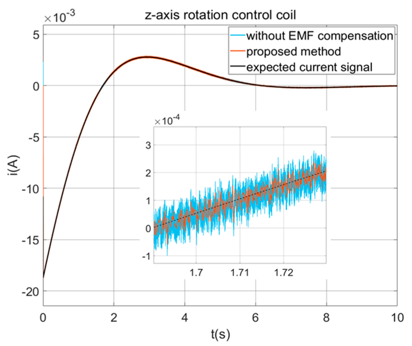
Section 4, the effectiveness of the proposed composite control scheme is validated through simulation. Finally,
Section 5 presents the conclusions of this paper.
3. Composite Controller Design
3.1. VSFPWM Based on Current Ripple Prediction
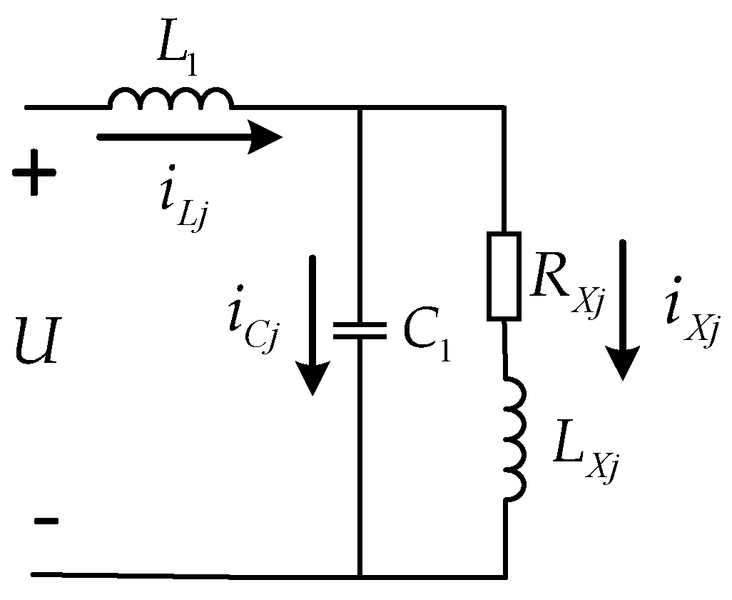
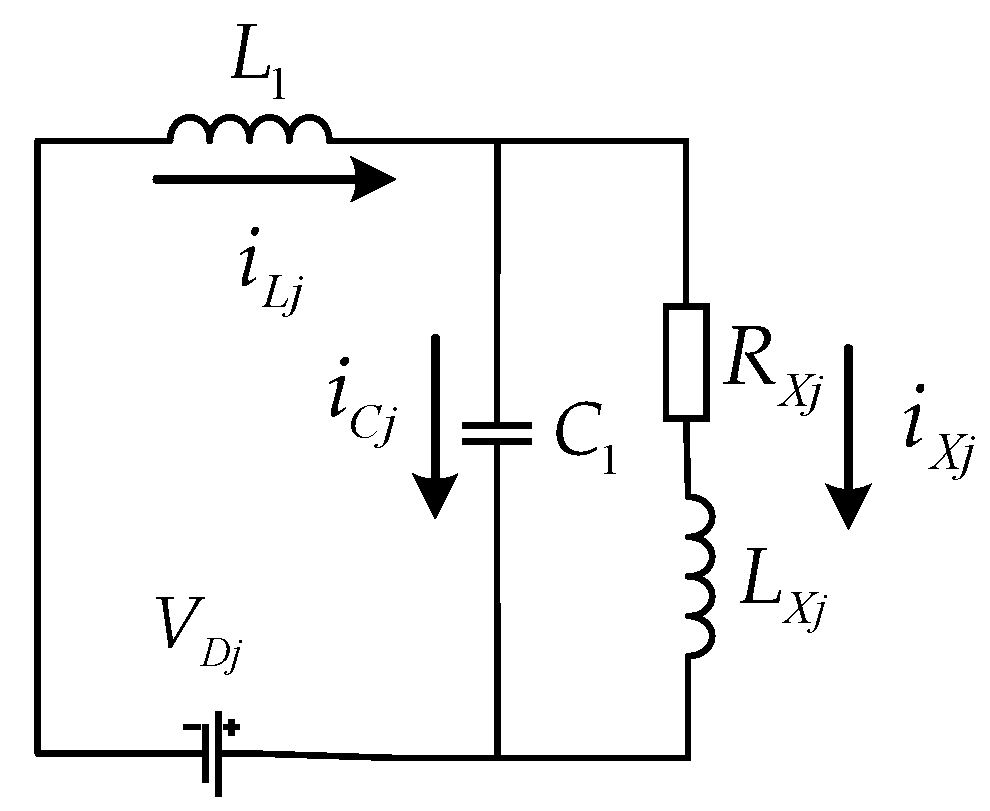
Compared with linear power amplifiers, switching power amplifiers are widely used in driving circuits due to their advantageous high efficiency. However, switching power amplifiers suffer from the current ripple problem, which can reduce the output precision of the driving current. According to Kirchhoff’s current law, the current ripple on the coil is positively correlated with the current ripple on the filter inductor of the power amplifier.
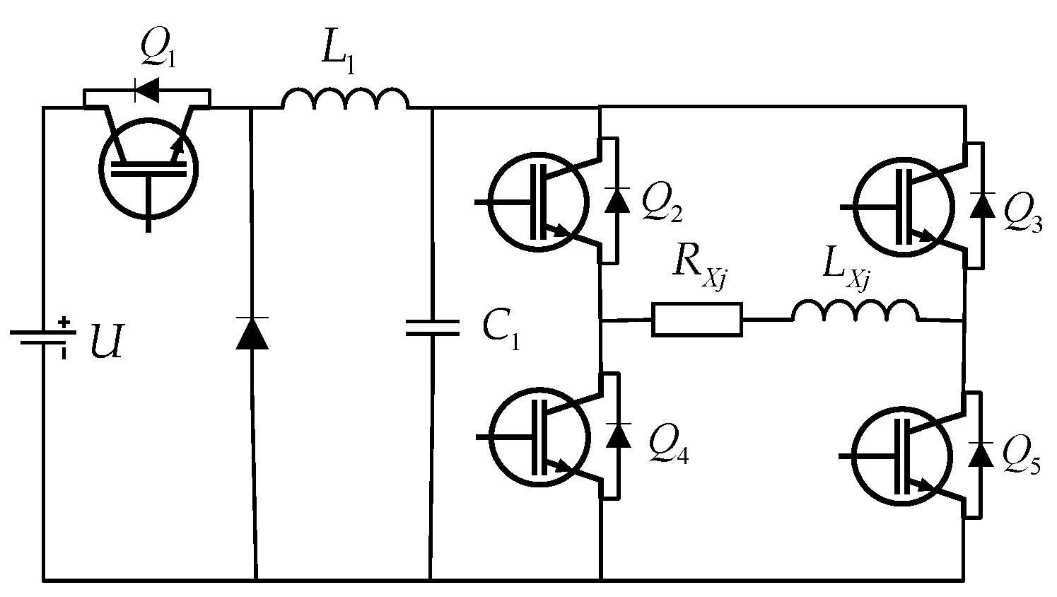
Considering the topology of the power amplifier shown in
Figure 4, assuming that the switching frequency is much higher than the fundamental frequency, and that the capacitor
C1 in the BUCK voltage regulator can make the driving current ignore the influence of voltage ripple, the fundamental component of the voltage between the two poles of a power amplifier is equal to the duty cycle multiplied by the power supply voltage
U(
t). The current ripple on the filter inductor of the power amplifier can be represented as follows:
where
Uoj represents the voltage across the terminals of each coil in the NCAESS;
Dj(
t) is the modulation wave amplitude output by the driving current controller of each coil, having a range of 0 ≤
Dj(
t) ≤ 1;
Tsj stands for the triangular carrier switching period of each driving current controller; and
fsj is the triangular carrier switching frequency.
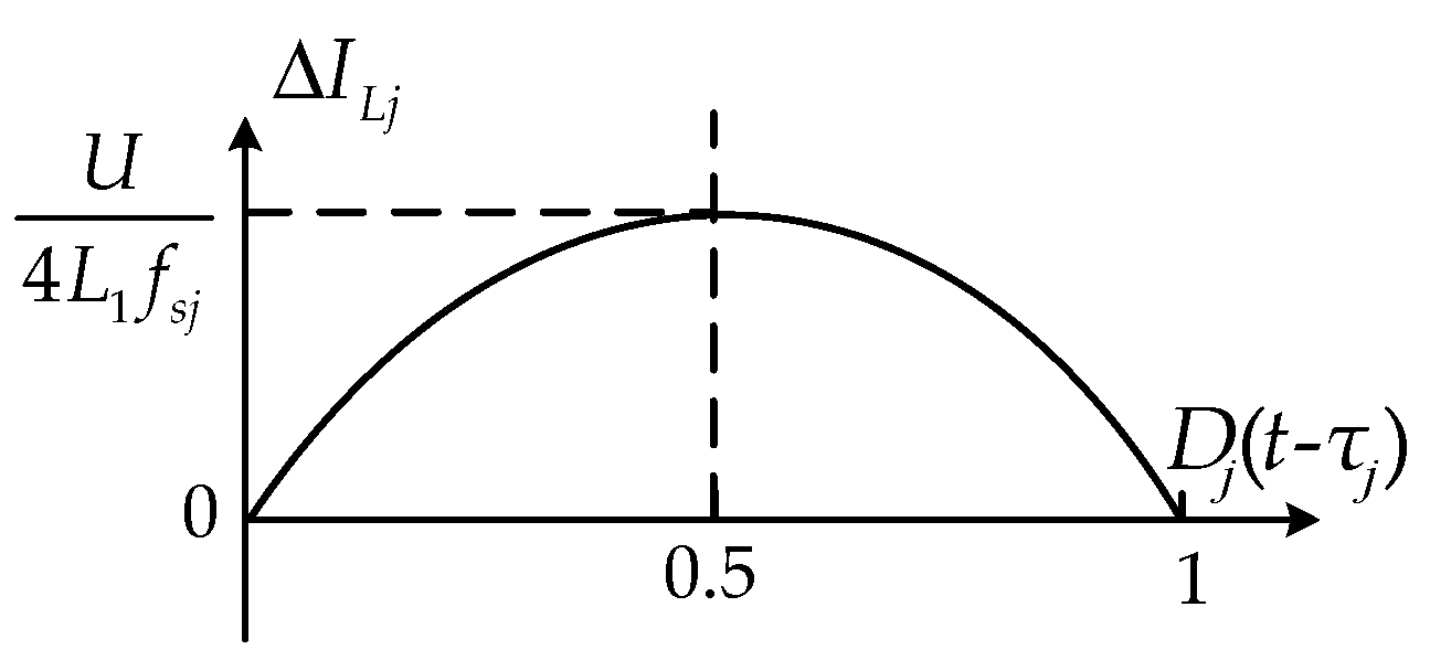
According to Equation (14), it can be seen that the amount of current ripple on the filter inductor is related to the modulation wave amplitude (i.e., the duty cycle), the triangular carrier frequency, and the filter inductor value. The current ripple decreases as the triangular carrier frequency and inductance value increase, while the current ripple and modulation wave amplitude have a nonlinear relationship, as shown in
Figure 8. When the modulation wave amplitude is 0.5, that is, when the duty cycle is 50%, the ripple is the largest. When the modulation wave amplitude is larger or smaller than 0.5, the ripple also decreases.
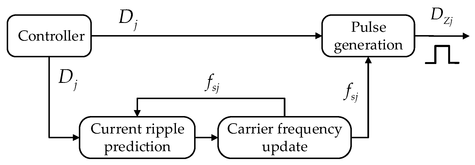
From the above analysis, it can be seen that when the current ripple changes with the change in duty cycle, the current ripple can be reduced by increasing the inductance value or triangular carrier frequency, which is also the traditional method. However, increasing the inductance value is not conducive to the dynamic response capability of the system, and increasing the triangular carrier frequency will aggravate the switching loss. Therefore, this paper predicts the current ripple according to the modulation amplitude and adjusts the triangular carrier frequency adaptively by using the VSFPWM algorithm to control the power amplifier switching element, as shown in
Figure 9. According to the NCAESS precision requirements for current ripple, the VSFPWM algorithm updates the triangular carrier switching frequency online, and compares the updated triangular carrier with the modulated wave to generate the pulse that drives the power switching element.
The current ripple value after updating the switching frequency and the calculation of the switching frequency update can be written as follows:
where
fsj_last is the frequency of the triangular carrier before the frequency update; and Δ
ILj_predicted represents the predicted current ripple value on the filter inductor based on the previous switching frequency in each switching power amplifier. At the same time, the updated triangular carrier frequency is set to no less than 10 kHz in order to ensure normal current control at a low duty ratio. The predicted current ripple value is given as follows:
The VSFPWM algorithm predicts the current ripple size on the filter inductor and adjusts the switching frequency adaptively to reduce the current ripple based on the modulation amplitude value. This does not require an increase in the inductance value in the filter or the maintenance of a high switching frequency. Therefore, the dynamic response of the power amplifier can be improved and the switching losses can be reduced while suppressing the current ripple.
3.2. Feedforward Compensation for Back Electromotive Force
In the attitude maneuver of the NCAESS, the PM moves first and the SM follows. Due to the non-contact connection between these two modules, there is a gap between them; at this time, the relative motion of attitude or position will occur between the two modules of the NCAESS. When entering the steady-state mode, the PM exhibits high attitude accuracy and stability, but the vibration and other disturbances on the SM will cause the position and attitude of the SM to change slightly, resulting in relative motion between the two modules. According to Faraday’s law of electromagnetic induction, the relative motion between the two modules would cause back electromotive force. The generation of back electromotive force will interfere with the driving current and affect the relative motion of the NCAESS.
In order to suppress this impact, this section adopts feedforward compensation to suppress the back electromotive force.
As shown in
Figure 2, the outer coil generates a back electromotive force on the NCAESS when the two modules are rotated relative to each other around the
x- and
y-axes. The magnitude of the back electromotive force can be written as follows:
where
ωsspi(
i =
x,
y) represents the angular velocity of the relative rotation along the
x-axis and
y-axis between the two modules.
The disturbances of the back electromotive force generated by the relative rotation around the
z-axis and relative translation along the
x-axis and
y-axis of the two modules can be represented as follows:
where
ωsspz and
vsspi(
i =
x,
y) represent the angular velocity of the relative rotation along the
z-axis and the relative velocity of the translation along the
x-axis and
y-axis between the two modules, respectively.
According to the average state-space equation of the power amplifier, as shown in Equation (12), and the NCAESS back electromotive force model constructed in Equations (18)–(20), the feedforward compensation controller of the back electromotive force can be obtained as follows:
where
Ebjx (
x = 1, 2, 3) represents the magnitude of the back electromotive force on each coil, and
Ebj1 (
j1 =
a1b1c1d1,
a2b2c2d2,
m1n1p1q1,
m2n2p2q2) =
Eb1,
Ebj2 (
j2 =
zr) =
Eb2,
Ebj3 (
j3 =
xt,
yt) =
Eb3.
Based on the constructed feedback compensation controller for back electromotive force, its impact can be effectively suppressed, thereby improving the precision of the driving current when the two modules move relative to each other.
3.3. Robust Smith Prediction for Eliminating Time Delay
Compared to analog control, digital control offers greater robustness and the ability to compute more complex algorithms. However, inherent time delays are introduced in the signal acquisition, algorithm computation, and PWM generation stages. The transfer function of a closed-loop control system for current control with delays can be written as follows:
where
iXjref(
s) represents the reference current of each coil;
iXj(
s) denotes the NCAESS driving current;
τj is the delay value in the driving current control system for each coil;
Gpj(
s) stands for the actual model of each power amplifier with delay; and
Gcj(
s) represents the closed-loop controller model for the driving current of each coil.
Due to the high-precision control requirement of the NCAESS, the presence of the time delay term
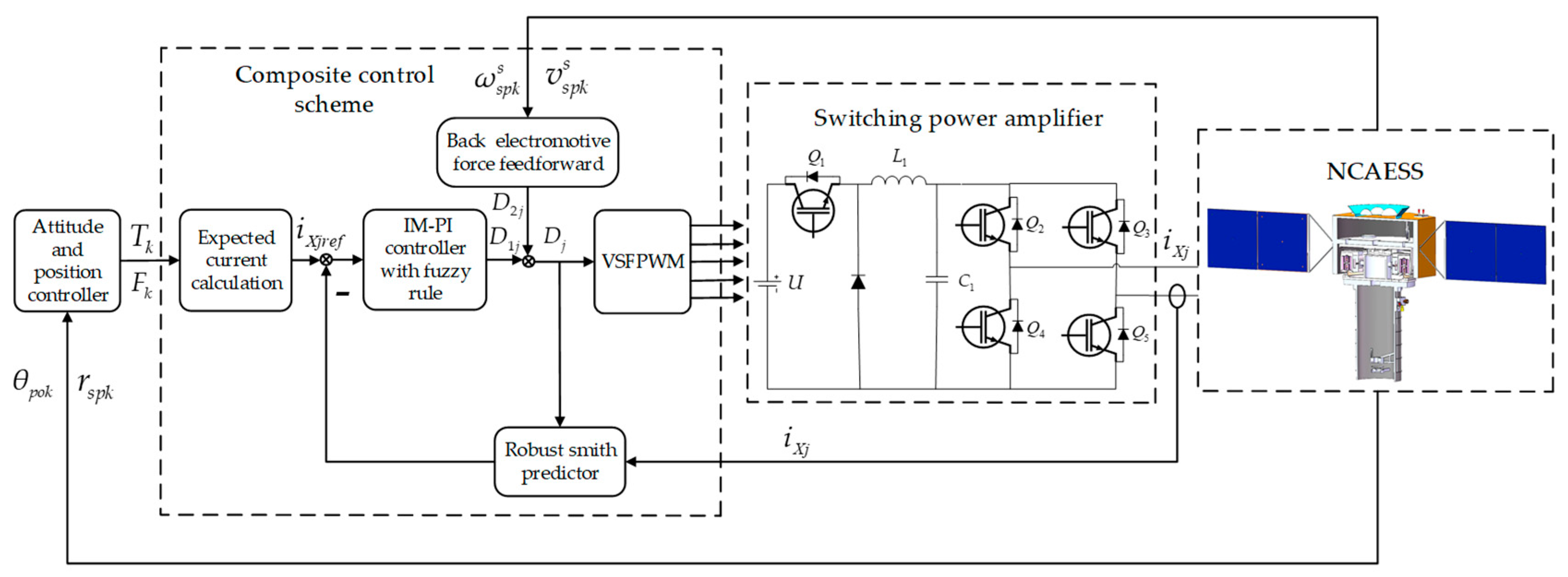
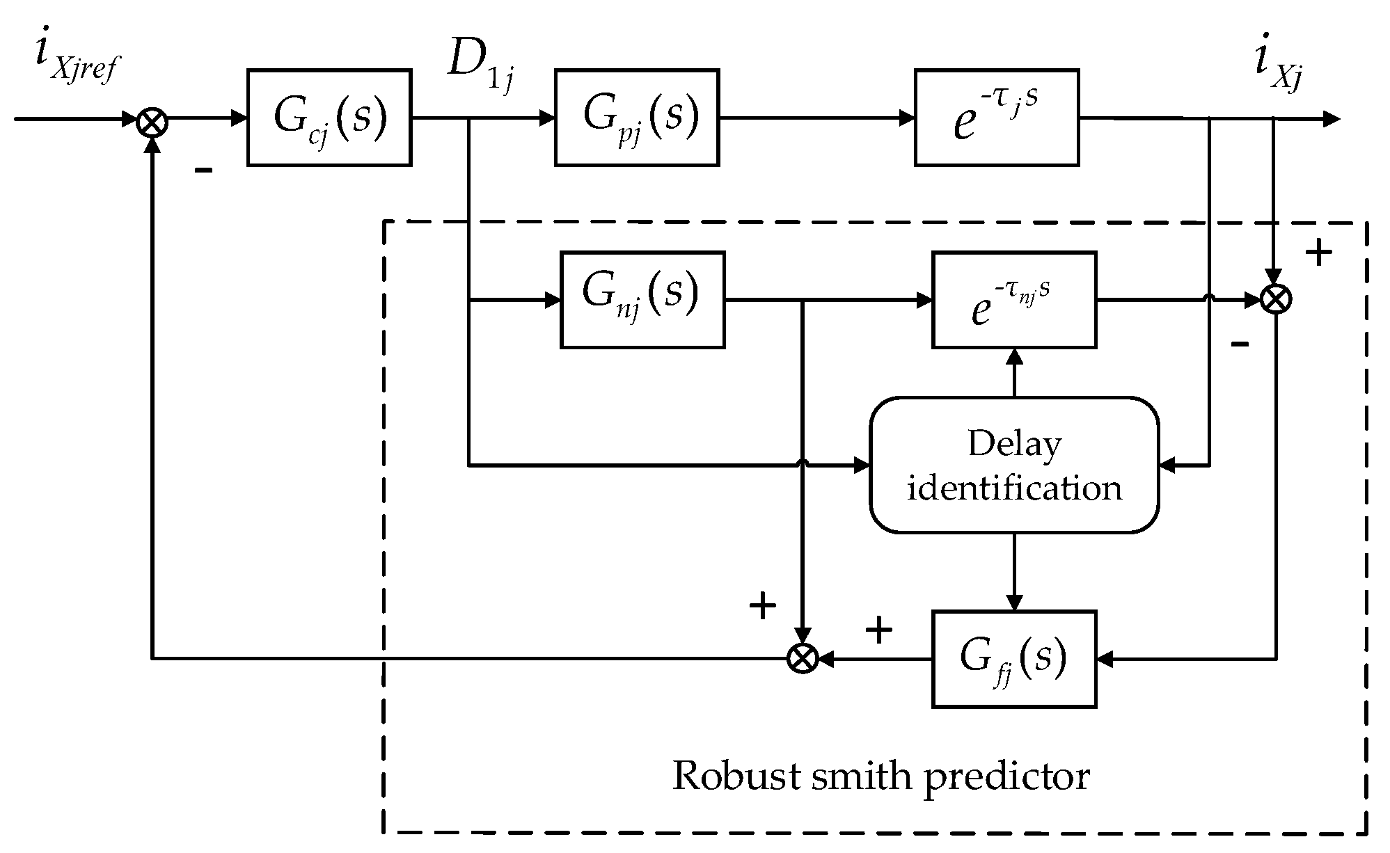
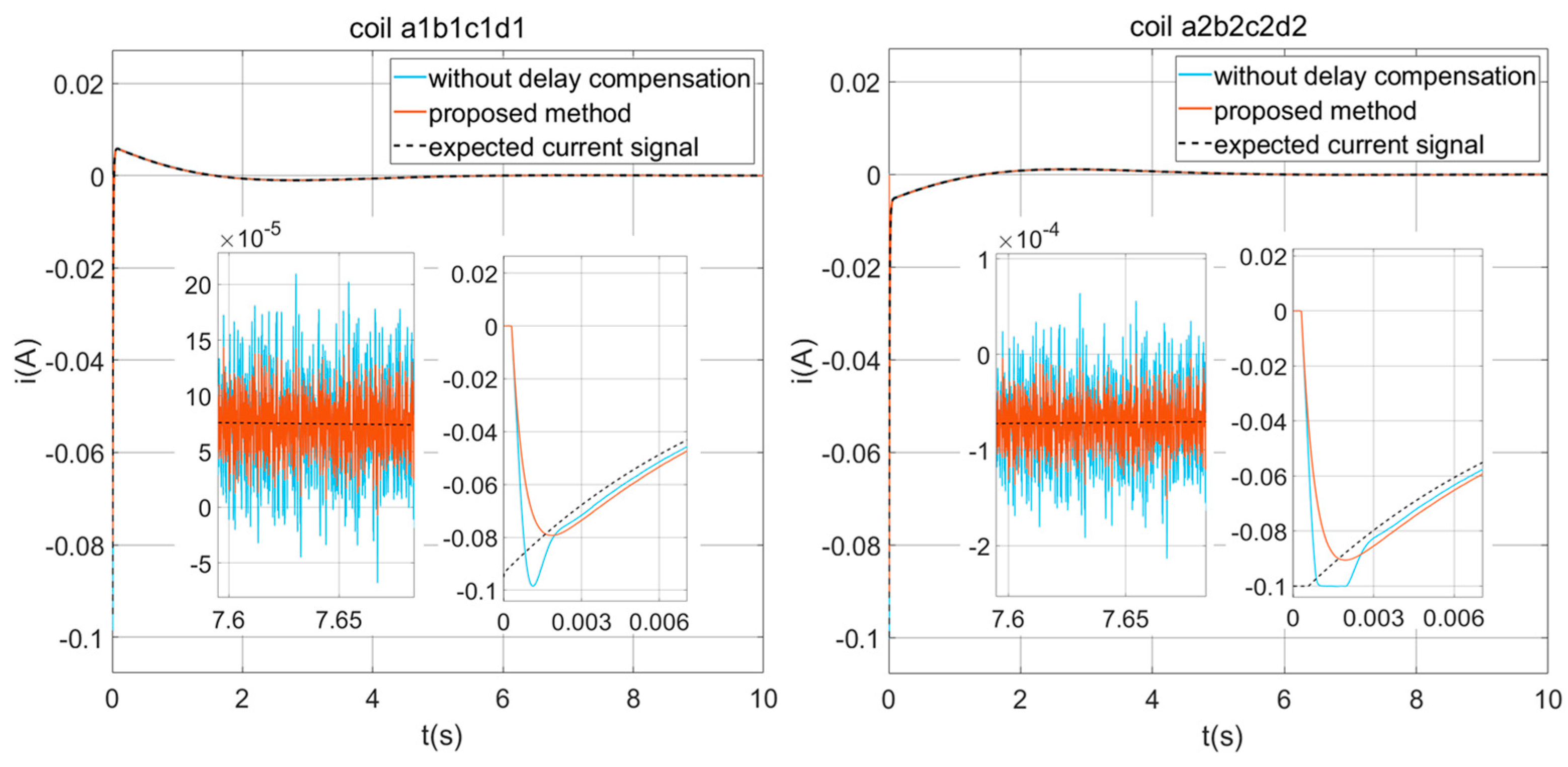
in the characteristic equation of the closed-loop control system can affect the stability of the system. However, due to the modeling and parameter identification errors caused by the time-varying performance of the power amplifiers, as well as the uncertainty of time delay, it is difficult to achieve ideal compensation effects with the classical Smith predictor. This section thus adopts the robust Smith predictor to identify the time delay online and compensate for the impact in the closed-loop control system. The structure of the robust Smith predictor is shown in
Figure 10.
As shown in
Figure 10,
D1j represents the output of the closed-loop controller for the driving current of each coil,
τnj is the estimated time delay for each driving current control loop,
Gnj(
s) represents the ideal model of each power amplifier after removing the time delay, and
Gfj(
s) stands for the filter designed in the RSP used in each control loop. Assuming that the back electromotive force is eliminated through the feedforward compensation, and since
L1C1LXjd3iXj(
t)/
dt3 +
L1C1RXjd2iXj(
t)/
dt2 (
L1 +
C1)
diXj(
t)/
dt +
RXjiXj(
t) for the fundamental current, the average state-space equation of the power amplifier can be simplified as shown in Equation (23) after neglecting the effects of the higher-order terms:
The ideal model of the power amplifier is written below:
Based on the correlation between the control input signal and the driving current, this paper employs a cross-correlation function to compute the delay time. The cross-correlation function between the control input and the driving current is as follows:
where
iXj(
t −
τ) is the driving current in each coil under the influence of the time delay; and
T is the observation time.
N data are sampled at equal time intervals
ts for the closed-loop control quantity and driving current, respectively. For the sampled data,
D1jT = [
D1j (
J),
D1j (
J + 1),…,
D1j (
J +
N − 1)],
iT = [
i(
J + nj),
i(
J +
nj + 1),…,
i(
J +
nj +
N − 1)],
J = 1,…,
m, where
m is a positive integer and
nj = τj/
ts. Assuming the time delay interval is [
τjmin,
τjmax] and making
Nts ≥
τjmax, the cross-correlation function between the control input and the output signal in the discrete-time form can thus be obtained as follows:
This paper adopts the fast Fourier transform (FFT) to calculate the cross-correlation function in Equation (26) in order to reduce the computational complexity. If is taken as the maximum value of the cross-correlation function, then the estimated time delay of each control loop using digital control is τnj = ts.
The closed-loop transfer function of the NCAESS when using robust Smith prediction can be written as follows:
The design of the filter is as follows:
When the online identification delay of each control loop
τnj ≈
τj, the filter
Gfj(
s) can be simplified into Equation (29):
At this point, the characteristic equation of the NCAESS driving current control system for each coil is 1 + Gcj(s)Gpj(s) = 0. From this, it can be concluded that when the power amplifier exhibits time-varying performance and disturbances leading to model uncertainty, the robust Smith predictor can still eliminate the impact of the digital control delay.
3.4. Internal Model PI Controller with Fuzzy Rule
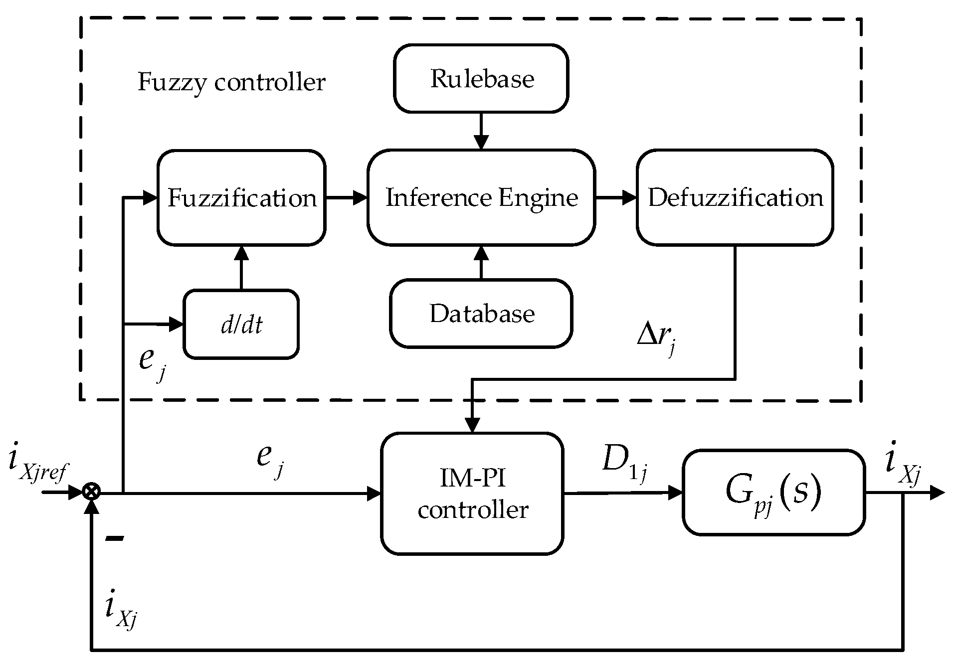
In order to address the impact of power amplifier variation and noise interference on driving current control, it is necessary to tune the controller parameters adaptively. The two parameters of the traditional PI controller would affect the control effect, and it is also difficult to achieve the ideal control results through manual adjustment of these parameters. Moreover, they cannot adaptively adjust with changes in system performance, disturbances, and other influences, which would weaken the robustness of the driving current. This article first uses the internal model principle to tune the parameters of the PI controller, and then combines it with fuzzy rule in order to enable it to adjust the parameters of the internal model PI controller adaptively. A structural diagram of the internal model PI controller with fuzzy rule is shown in
Figure 11.
The controller constructed based on the internal model principle is shown in
Figure 12, which consists of feedback from the ideal model of the power amplifier and a low-pass filter controller of the same order as the controller. The internal model controller is constructed as shown in Equation (30).
where
rj represents the filter parameter. The equivalent feedback for internal model control is constructed as follows:
We can thus transform the structure of the traditional PI controller through the following expression:
where
kpj and
kij are the parameters of the PI controller; and
kpj/
kcj is the equivalent parameter of
kij.
Comparing Equation (31) with Equation (32), the internal model PI controller is constructed as follows:
As shown in Equation (34), it can be observed that the PI controller is only related to the parameter rj of the filter when the ideal model of the NCAESS is known. Based on the design experience of the filter parameters, the PI controller can be tuned effectively. This reduces the difficulty and improves the precision of the parameter tuning.
By adjusting the filter parameter rj, it is found that as the value of rj decreases, the system response speed can be increased and the robustness can be enhanced. However, too small a value of rj may lead to the system overshooting. On the other hand, increasing the value of rj would reduce the response speed and robustness, but would not cause overshooting. In order to balance the overshooting and response speed of the NCAESS driving current control system and to improve the robustness, this paper adopts a fuzzy rule to adjust the filter parameter r adaptively based on the current system situation.
The internal model PI controller with fuzzy rule takes the error
ej between the reference current and the feedback current as well as the changing rate of the error
ecj as input variables, and the change in the parameter
rj of the internal model PI controller Δ
rj as the output variable. The Gaussian-type function shown in Equation (33) is used as the membership function of the fuzzy controller. The fuzzy subsets corresponding to the input and output variable domains of the fuzzy controller are {NB, NM, NS, Z, PS, PM, PB}.
where
ai is the center value of the function; and
bi is the width of the function.
After obtaining the output of a fuzzy rule, it is necessary to perform defuzzification to obtain precise control values. This paper adopts the centroid method for defuzzification [
26], which is represented as follows:
where
Mj represents the centroid position of the fuzzy set;
xj denotes the changing rate of
ej and
ecj; and
μ(
xj) represents the membership degree of the variable
xj.
Combining the above contents, the internal model PI controller with fuzzy rule can be represented as follows:
Obviously, the internal model PI controller with fuzzy rule can be adopted to change the controller parameter rj adaptively according to the current error situation of the driving current control system, thereby improving the driving current performance.
5. Conclusions
This paper presents a composite strategy for the driving current control of NCAESS, which addresses various disturbances that affect the precision of the switch power amplifiers. These disturbances include the switch ripple, back electromotive force, digital time delay, time-varying performance, and noise disturbances. The proposed method combines the VSFPWM, back electromotive force feedforward compensation, the robust Smith predictor, and an internal model PI algorithm with fuzzy rule to mitigate the above-mentioned disturbances effectively. Through numerical simulations comparing the composite control scheme with the traditional method, it is demonstrated that the proposed method can be adopted to improve the driving precision. Specifically, the VSFPWM maintains the peak value of the current ripple within a range of 100 μA. The back electromotive force feedforward compensation roughly doubles the precision in situations of low-current output. The robust Smith predictor enhances the system stability, reduces the driving noise by a factor of two, and alleviates the overshooting problem caused by time delay. Overall, the proposed composite control scheme in this paper strengthens the robustness and dynamic response, and can thus be adopted to guarantee the high-precision control of NCAESS.








_Zhu.png)


