Abstract
Despite considerable research effort in the past 60 years, the occurrence of combustion instabilities in rocket engines is still not fully understood. While the physical mechanisms involved have been studied separately and are well understood in a controlled environment, the exact interaction of fluid dynamics, thermodynamics, chemical reactions, heat-release and acoustics, ultimately leading to instabilities, is not yet known. This paper focuses on the investigation of flame-acoustic interaction in a model combustion chamber using detached-eddy simulation (DES) methods. We present simulation results for a new load point of combustion chamber H from DLR Lampoldshausen and explore the flame response to resonant and non-resonant external excitation. In the first part of the paper, we use time-averaged results from a steady-state flow field without siren excitation to calculate the combustion chamber Helmholtz eigenmodes and compare them to the experimental results. The second part of the paper presents simulation results at a non-resonant excitation frequency. These results agree very well with the experimental results at the same condition, although the numerical simulation systematically overestimates the oscillation amplitudes. In the third part, we show that a simulation with resonant siren excitation can correctly reproduce the shift in eigenmode frequencies that is also seen in the experiments. Additionally, for this new load point, we confirm previous numerical results showing a strong influence of transversal excitation on the shape of the dense LOx cores. This work also proposes a bombing method for determining the resonant eigenmode frequencies based on an unexcited steady-state DES by simulating the decay of a strong artificial pressure pulse inside the combustion chamber.
1. Introduction
Unwanted combustion instabilities in rocket thrust chambers have been a major engineering problem since the Apollo age [1] in the 1960s and still pose a serious risk in the design of new engines today. Combustion instabilities are strong acoustic disturbances caused by the constructive coupling of pressure waves with unsteady heat-release that may lead to catastrophic failure of the engine and loss of the launch vehicle. Even though they have been subject to many investigations in the past 60 years, a detailed understanding how different physical processes interact to develop combustion instabilities is still missing.
The most prominent example of combustion instabilities in flight rocket engines is the Saturn-V F-1 main stage engine. Being a key element for the Apollo missions to the moon, the development of the F-1 engine was afflicted by strong combustion instabilities already in early tests between 1959 and 1960 [1,2]. In October 1962, it was then decided to systematically investigate the combustion instabilities during the so-called Project First.
Even though the root cause of the F-1 combustion instabilities could never be clearly identified, a redesign of the injector head baffles (for an overview of the different configurations tested, see Figure 3 in the paper of Oefelein et al. [2]) eventually reduced the instabilities to an acceptable level for human spaceflight. Also, other engine developments suffered from serious combustion instabilities. This includes the LOx/H2-operated J-1 engine, which was used in the second and third stage of Saturn-V [3]. In Europe, the development of the HM-7/HM-7B engine for the Ariane program was also plagued by high-frequency combustion instabilities and chugging under unfavorable ignition conditions [4]. Also, the Japanese space program suffered from problems with combustion instabilities in their LE-9 (formerly LE-X) engine [5], which were eventually overcome by an oxygen injector redesign.
Due to the harsh flow environment inside a rocket engine (very high pressures and temperatures exceeding 3500 K), the only experimentally available variables are often pressure measurements and, in the case of laboratory-scale combustion chambers, visualizations of the flame field using optical methods. Numerical simulations are therefore an indispensable tool for providing more detailed insights into the flow topology and physical processes in combustion chambers.
This work investigates the interaction of a flame with forced transverse acoustic oscillations in model combustion chamber H (Brennkammer H, BKH) from DLR Lampoldshausen at transcritical conditions. BKH has been used extensively in the past in various experimental [6] and numerical studies with URANS [7,8] and LES [9]. The purpose of the current study is to compare the flame response between a resonant and non-resonant transversal excitation for a new operating point of BKH with a cryogenic fuel temperature of 61.9 K. Experimental studies at the NASA Lewis Research Center in the 1960s [10,11,12] (for an overview of newer studies on hydrogen temperature effects see Gröning et al. [13]) showed higher susceptibility to combustion instabilities if the hydrogen temperature was very low. This work is therefore a first step towards a better understanding of the effect of hydrogen temperature on the unsteady flame response in rocket combustion chambers, and serves as a complementary study to previous works with gaseous hydrogen [7,9]. The results shown in this paper summarize several key findings of the PhD thesis [14] of the first author.
2. Experimental Setup
Combustion chamber H (BKH) is an experimental rocket combustion chamber that has been designed by DLR Lampoldshausen [6] with the specific goal of investigating flame-acoustic interactions. Readers seeking detailed description of the experiment are directed to Refs. [15,16]. BKH has a rectangular shape with five primary shear coaxial injection elements positioned around its central axis. In each of these injectors, cryogenic oxygen is injected through the central pipe ( = 0.576 kg/s), while cold hydrogen is injected coaxially at a rate of = 0.1 kg/s. Compared to its length, the combustor only has a small width that allows optical access through windows embedded in the chamber side walls (see also Figure 1).
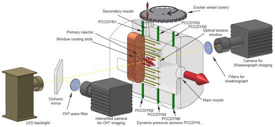
Figure 1.
A schematic overview of BKH including the dynamic pressure sensor locations. The main flow direction (marked by the colored arrows) is referred to as the axial direction. Likewise, the vertical direction towards the secondary nozzle is referred to as the transversal direction.
Combustion chamber H is equipped with a large main nozzle in the axial direction and a smaller secondary nozzle at the top of the combustor. This secondary nozzle can be periodically closed by a toothed exciter wheel (siren) that excites transversal and longitudinal pressure oscillation in the chamber. In addition to the five main injection elements, BKH features 50 secondary H2 injection elements above and below the primary injectors to prevent large-scale recirculation of hot gases in the volumes next to the primary injectors. The large relative mass flux of secondary injectors compared to the combined flux of the primary injectors effectively confines the flames to the center third of the chamber volume. Small-scale recirculation is nevertheless observed in the spaces between the outer four primary injectors and the first row of secondary H2 injectors.
The side windows are actively cooled by a H2 film injection through slots at the faceplate. In the test run, BKH was operated at the test stand P8 at DLR Lampoldshausen which provides fuel and an oxidizer at the required cryogenic conditions and mass flow rates. This work presents the first simulation results of a BKH test run with cryogenic oxygen ( = 125.5 K) as well as cryogenic hydrogen ( = 61.9 K). BKH operates at a combustion chamber pressure of = 60.19 bar. The ratio of the primary oxygen-to-hydrogen mass flow rate (ROF) results in , which is close to typical specific impulse-optimal values for real engines. The mass flow rate of the propellants are measured by turbine flow meters in the feedlines supplying the combustor. The combined measurement error from the flowmeters results in an uncertainty in ROF of ±3%. Combustion chamber H is instrumented with dynamic pressure sensors (labelled PCCDYN) on the chamber walls, arranged as indicated in Figure 1. The sensors are of piezoelectric type manufactured by Kistler and are sampled with 100 kHz in the BKH tests. Optical techniques like shadowgraphy and OH* emission measurement can be applied for the investigation of the flame response through the side windows.
In a typical test run for the BKH experiment, the siren frequency is linearly ramped up from low to high frequencies at a speed of 75 Hz/s. Every time the siren frequency coincides with the discrete combustion chamber eigenmodes, resonance occurs, and the unsteady pressure oscillation amplitude is significantly increased. Such a test run is depicted in Figure 4 of [15], which shows the evolution of the combustion chamber pressure, ROF and excitation frequency, as well as the acoustic signal from one of the dynamic pressure sensors PCCDYN2.
Figure 2 shows the power spectral density of the experimental pressure signal for two siren excitation frequencies. The red curve shows the pressure spectrum for a resonant 1T excitation at 4000 Hz, while the blue curve represents a non-resonant excitation at 4850 Hz, not coinciding with any combustion chamber eigenmode. Both curves have their maxima at the respective excitation frequency and show additional peaks that have been labeled with the corresponding combustion chamber eigenmode shape at the secondary x-axis. The eigenmode frequencies differ between the resonant and the non-resonant excitation. This shift to higher frequencies has been explained [17] by a flame contraction and subsequent change in the speed of sound field when the flame is exposed to high-pressure oscillations. While the experimental 1L mode is only weakly affected by the strong siren excitation at resonant conditions, the 1L1T and the 2L1T mode show a considerable shift of = 200–250 Hz towards higher frequencies. For the resonant 1T mode, there appears to be a similar shift towards higher frequencies, but the true eigenmode frequency is difficult to identify because of the proximity to the excitation frequency at 4 kHz. Another interesting feature of the non-resonant excitation is the 2L mode, which is not visible for the resonant excitation.
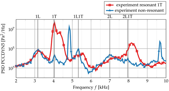
Figure 2.
Pressure power spectral density at sensor PCCDYN5 in resonant and non-resonant conditions. For the position of the sensor on the chamber wall, see Figure 1. The eigenmode shapes, as indicated on the secondary x-axis, correspond to the non-resonant modes of the chamber.
3. Numerical Setup
This work uses the DLR TAU code [18] to simulate BKH at the described operating conditions. TAU is a second-order compressible finite-volume scheme for solving the Navier–Stokes equations [14,19] on hybrid, fully unstructured and structured meshes. It has been applied to a large variety of applications ranging from the low subsonic regime up to hypersonic flows. The standard solver uses an edge-based dual-cell approach based on a vertex-centered scheme. Time-accurate simulations are performed using a Jameson-type dual time-stepping approach with a physical time-step size of s. The time integration in the inner iterations is based on an explicit Runge–Kutta scheme that uses a local time-stepping approach for convergence acceleration. All simulations presented here use a corrected version [20] of the MAPS+ [21] upwind solver that shows greatly reduced numerical dissipation at high wave numbers. A more detailed discussion on spectral properties of the corrected MAPS+ scheme, along with the validation using canonical test cases, can be found in the PhD thesis [14] of the first author.
The simulations use a hybrid mesh consisting of 38 million grid points. For a visual representation of the mesh, please see Figure 3a,b. The near-flame region behind the primary coaxial injectors is resolved by separate structured hexahedral blocks. The central flame region is connected to the boundary layer mesh by unstructured tetrahedra of varying size. Viscous chamber walls are discretized by elongated prism layers with a nondimensional first cell normal spacing of .
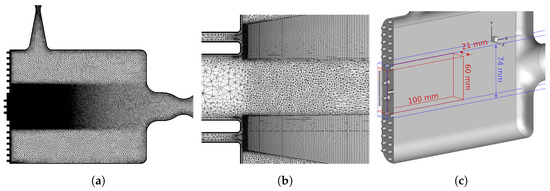
Figure 3.
Depiction of the computational mesh and the central injector region. (a) shows the total view of the mesh in the central plane. (b) shows a zoom into the mesh transition region near the central injection elements. (c) shows the central injector region (red boundaries) and the zonal LES region (blue).
TAU has also been extended for scale resolving simulations by using various large- and detached-eddy simulation models [22,23]. These models have also been successfully applied to fundamental investigations of launch vehicle aerodynamics [24]. This work uses a Spalart–Allmaras-based zonal detached-eddy simulation approach in which the region around the five central shear coaxial injectors is treated as an LES zone (see the blue volume in Figure 3c). This zone also includes the first row of secondary injection elements above and below the main injectors to cover the most important parts of the flame. All remaining parts of the combustion chamber are simulated using the URANS model.
The real-gas thermodynamic properties [25] of gas mixtures are modeled using the cubic Soave–Redlich–Kwong equation of state [26]. A mixture of the species O2, OH, H2, H, H2O and O is used. In this gas mixture, the cryogenic components H2 and O2 are computed using cubic equation-of-state coefficients, while the remaining species are treated as ideal gases.
Chemical reactions are taken into account using a flamelet combustion model [27]. This model is strictly valid only when the chemical reactions proceed much faster than the turbulent time scales. Experimental investigations [28] for the same operating pressure in a different combustion chamber show that the turbulent time scale in the shear layer is approximately 1 µs. This study also indicates that the chemical time scale is of similar order. However, it has been shown [29] that the flamelet model is still valid for high-pressure liquid rocket simulations of H2/LOx flames even when the chemical time scale is of similar order. Therefore, a counter flow diffusion flame model can be applied here. This model is then reduced to the set of one-dimensional flamelet equations [30], which are solved for the species mass fractions and the enthalpy h as a function of the mixture fraction Z:
In this set of equations, denotes the gas mixture density, the species enthalpy for a given species s, the isobaric heat capacity of the gas mixture and denotes the chemical source term for species s. This set of equations is solved on a non-equidistant grid in the mixture fraction Z space including the exact same thermodynamic gas models that are used in the TAU code (cubic equations of state or a high-accuracy description using Helmholtz-energy-based formulations [31]). The flame shape is determined by the profile of the scalar dissipation rate:
Here, is the stoichiometric scalar dissipation rate, which is a measure of the strain rate in the flame.
As all simulations presented in this work are very close to chemical equilibrium due to the high pressure in BKH, only a near-equilibrium flamelet with is used. Furthermore, laminar chemistry is assumed, therefore neglecting any turbulence–flame interaction. These simplifications effectively reduce the flamelet model to an infinitely fast chemistry model which still accounts for the correct treatment of cryogenic gas properties. In order to reduce the computational cost even further, the cubic mixture coefficient and its temperature derivatives are stored in the flamelet table [32]. Transport coefficients are also pre-calculated and stored in the flamelet table. The flamelets are calculated under the assumption of unity Lewis number , where Sc and Pr are the Schmidt and Prandtl number, is the dynamic viscosity, the thermal conductivity and the isobaric heat capacity. This assumption is used to simplify the numerical heat-flux vector in TAU [19] from
to
Hence, the assumption of unity Lewis number removes the requirement [14] of solving transport equations for all participating species separately, and leaves the heat-flux vector only proportional to the gradient of enthalpy .
The flamelet approach allows for arbitrarily complex chemistry schemes at constant computational cost and is therefore a promising candidate for scale-resolving combustion simulations of complex future fuels, e.g., CH4/O2. This newly implemented real-gas flamelet approach has been validated [14] against published direct numerical simulation results from Ma et al. [32] and Lacaze et al. [33].
A siren outflow boundary condition is used in this work. This boundary condition periodically replaces parts of the siren nozzle outflow boundary condition with a viscous wall. The siren blockage oscillates between 0% and 100% at the given siren frequency. All combustion chamber walls use an adiabatic no-slip boundary condition. At the various inlets, mass flux boundary conditions are used. At the nozzle outlets, a pressure-exit outflow boundary condition is used.
The present work simulates half of the combustion chamber and uses a mirror symmetry boundary condition in the central plane in order to reduce the computational cost. Applying a symmetry boundary condition in the central plane will not alter the relevant chamber acoustic modes as the modes under consideration are located in the longitudinal and transversal (i.e., streamwise) direction. The symmetry boundary condition will only affect modes in the secondary transversal direction, i.e., in the direction of the side windows. As the width of BKH is small (50 mm) compared to its other dimensions, the fundamental frequency of this mode is of the order of 13 kHz and, therefore, already outside the range of interest for this work. Secondly, the two off-center flames are fully contained in the computational domain, while only the central flame is intersected by the symmetry boundary condition. Even though the movement of the central flame will be restricted, and the turbulent structures near the central plane will not be completely representative of true turbulence, it is assumed that the error on the overall flame-acoustic interaction will be small. Due to its position near a pressure node in the center of BKH, the central flame is contributing less to the overall flame-acoustic interaction compared to the off-center flames, which are fully resolved.
Apart from the validation efforts of the separate submodels, the complete simulation setup in TAU has been validated using the experimental results of combustion chamber C (BKC) [34]. Due to the lack of additional validation data at high-pressure conditions, results obtained with this simulation setup have also been compared to the purely numerical test case of Ruiz et al. [35]. Based on the validation reference data available, it can be concluded that the setup presented is sufficiently validated.
4. Pressure Signal Analysis and Mode Identification
This work compares the numerical to the experimental results mainly on the basis of the dynamic pressure sensor data. The positions of the pressure sensors along the combustion chamber walls are shown in Figure 1. For better comparability of the results, the numerical pressure sensor position is chosen as the surface mesh point nearest to the experimental sensor position. This section presents the data post-processing strategy for both the numerical and experimental data.
All pressure signals are filtered with a third-order Butterworth filter at 15 kHz. The power spectral densities (PSDs) of the experimental signals are calculated using Welch’s method [36] with a segment length of 2048 samples. In order to find a compromise between sufficient signal length and an instantaneous snapshot of the chamber pressure response, a signal length of 0.2 s is chosen. For the resonant condition at 4000 Hz, the pressure data is analyzed between 10 and 10.2 s. The non-resonant condition is defined at a siren excitation frequency of 4850 Hz between 21.6 and 21.8 s in the experiment.
The numerical pressure signals are much shorter than the experimental sensor data with 7.5 ms in the non-resonant case and 17.6 ms for the resonant condition. Their power spectral densities are calculated by periodograms. Compared to the acoustical timescale set by the 1T chamber mode at 4 kHz, the simulation samples 30 cycles for the non-resonant case and 70 cycles for the resonant simulation. In our opinion, these sample lengths are long enough to derive sufficiently converged time-averaged combustion chamber mode shapes. Based on the low-speed dominated fluid dynamical timescale, the sample length could certainly be increased. This, however, comes at a very high computational cost. It should also be kept in mind that the unsteady simulation was restarted from a well-converged steady RANS solution, which by itself gives a very good estimate of the low-speed region of the flow near the corners and the walls.
Eigenmode identification for the numerical data is performed using dynamic mode decomposition [37] (DMD) of the complete time-resolved wall surface pressure distribution. For a better comparability of the DMD results to the PSD data, the DMD algorithm uses the same sample length as the single-point pressure data. DMD decomposes the unsteady pressure response into discrete single-frequency modes (characterized by oscillation frequency and a damping/growth rate ) and their corresponding spatial mode shapes. DMD is a useful tool to match the peaks in the pressure signal PSD to spatial mode shapes and, therefore, identify the dominant modes inside the combustion chamber. This complementary approach allows us to quantitatively compare the experimental and numerical pressure signals over the whole spectrum while being able to identify the most important eigenmode shapes from the dominant DMD modes based on matching frequencies. The applied DMD methology is well suited for identifying combustion chamber eigenmodes due to the fact that they have well-defined mode center frequencies and are usually spectrally isolated.
5. Results
This section presents the numerical simulation results for combustion chamber H. The first part explores the steady-state properties of the flow field without siren excitation. Results from this part are the basis for the calculation of the Helmholtz combustion chamber eigenmodes. The second part of this paper presents results from a non-resonant simulation and compares them to the experimental results at the same excitation frequency. In the third part, a virtual bomb test approach is presented as a means to identify chamber eigenmodes based on unsteady simulation results. The last part investigates the flame response at a chamber resonance frequency. This paper then concludes with a summary of the results and an outlook for possible future work.
5.1. BKH Steady-State Simulation
The first step in simulating BKH’s flame response is to create a steady-state solution of the undisturbed flow field using a detached-eddy simulation. For this, the DES is restarted from a steady RANS solution, and it is continued until the turbulent structures (for an instantaneous image of the flame see Figure 4) are fully developed.
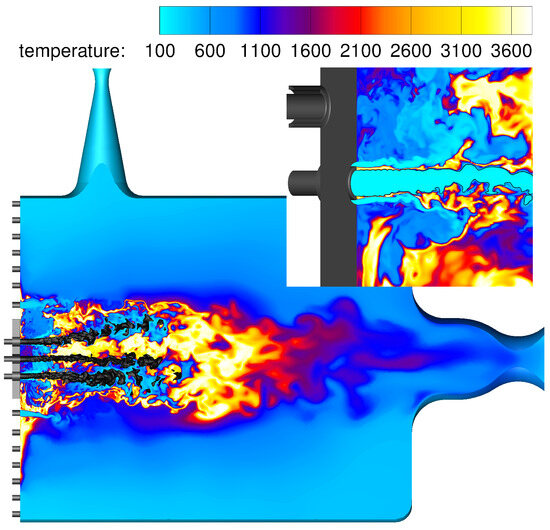
Figure 4.
Unexcited instantaneous flow field of BKH. The dense oxygen cores are visualized as a constant density surface at = 100 kg/m3. The inset image shows a zoom on the lower injector near the faceplate. The flame is anchored at the injector lip, and the flame sheet forms between the oxygen and the hydrogen stream.
Figure 4 shows the flame field that surrounds the central dense oxygen core. The central flame extends in transversal (i.e., siren direction) until the first row of secondary H2 injection elements. These injectors are also visible in Figure 4 because of the cold hydrogen being injected from the faceplate into the outer flame part.
Another noteworthy flow feature is a pocket of hot gas at the position of the first hydrogen secondary injector in the lower half of the combustion chamber. This hot gas region is attached to the faceplate and is most likely a remnant from the initialization phase. Near the faceplate, the flow velocity is very small causing a region of stagnant fluid with long residence time.
The simulation is continued for an additional 5.8 ms to statistically sample the flow field and compute first- and second-order statistics of the flow variables (e.g., density, flow velocity, speed of sound distribution).
Figure 5 shows a comparison between the averaged experimental shadowgraphy image and the averaged dense LOx core from the simulation in non-resonant conditions.

Figure 5.
Time-averaged shadowgraphy images from the experiment. The experimental image shows results from the off-resonant excitation. Subfigure (a) shows the time-averaged shadowgraphy images from the experiment. This image uses results from the off-resonant excitation. In subfigure (b), the time-averaged dense LOx cores from the simulation, shown as blue isocontours at 50 kg/m3, have been added.
Both images qualitatively show an outward bending of the lower and the upper LOx cores, while the central LOx jet is ejected horizontally. The experimental shadowgraphy image also indicates that the central core starts spreading at about 50 mm, a behavior which is well reproduced by the numerical simulation. The outer cores in the experiment spread out earlier compared to the numerical simulation. In the flame imaging in Figure 5, an asymmetry in the flame distribution is seen, which is understood to be due to the influence of the flow through the secondary nozzle in the upper wall on the global flow field in the chamber. This asymmetry affects the recirculation zones above and below the outer primary injectors, with a stronger (brighter) recirculation of hot gases visible in the bottom-left corner of Figure 5 below the lower two primary injectors.
A direct comparison between the experimental shadowgraphy images and the numerical data solely on the isocontours of the dense oxygen jets is difficult because other effects, e.g., light diffraction due to changes in the refractive index and absorption, may play a role. A more detailed analysis of the processes involved and an extension of OH* emission is given by Tonti et al. [38].
Figure 6 shows the time-averaged flow fields for temperature (a) and the speed of sound (b). It is important for the simulation to predict the correct speed of sound distribution inside the combustion chamber as this is the key parameter for determining the chamber eigenmodes. The correct speed of sound value, however, ultimately depends on the correct temperature and gas composition distribution.
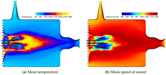
Figure 6.
Time-averaged flow fields for the unexcited steady-state DES results of BKH.
A region of reduced speed of sound is clearly visible around the dense oxygen cores. This region is surrounded by the hot flame which increases the speed of sound up to 2000 m/s. One also notices the stratification towards the top and bottom walls in the transversal direction due to the secondary H2 injection.
The detached-eddy simulation predicts the combustion chamber pressure to be at = 61.3 bar. This agrees well with the experimental chamber pressure of = 60.18 bar, even though the value is just outside the experimental uncertainty of 1%.
5.2. Helmholtz Eigenmodes Based on the Time-Averaged Steady-State Results
Before one can excite the flame at the eigenmode frequency of the combustion chamber, the simulation eigenmodes have to be determined first. This section presents eigenmode results from a 3D Helmholtz solver that is based on the time-averaged speed of sound field and the mean density field of the steady-state simulation results.
It is assumed that the combustion chamber geometry together with the speed of sound distribution forms an acoustic resonator that is governed by the Helmholtz equation, Equation (6):
Here, denotes a pressure fluctuation distribution which we solve for, is the wave number and denotes the fluid density. Due to the large gradients in density, the inhomogeneous Helmholtz equation [39] is used here. Together with the appropriate boundary conditions, this problem can be rewritten as an eigenvalue problem that is solved by the finite-element framework FEniCS [40]. A similar approach has been used successfully in previous studies of BKH [7].
In order to simplify the eigenmode problem of BKH to a Helmholtz equation, several assumptions have to be made. First of all, only small perturbations in a stagnant fluid are considered. This implies that there is no mean flow inside the combustion chamber. Additionally, all boundaries, including the in- and outflows, are treated as fully reflecting walls, and the injector tubes have also been neglected. This is an oversimplification of the real problem, especially at the inlet boundary condition. Here, an impedance boundary condition would be more suitable. Such a boundary condition has not been implemented yet.
Figure 7 shows the dominant Helmholtz eigenmodes of BKH.
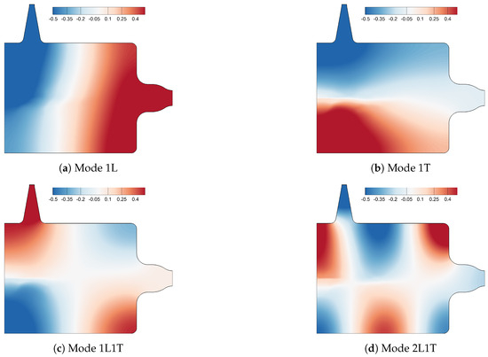
Figure 7.
Spatial Helmholtz mode shapes of BKH.
Their modal frequencies are compiled in Table 1. Even though the Helmholtz eigenmodes are calculated under various simplifying assumptions, the error in the mode frequency is 4.5% at most.

Table 1.
Comparison of experimental and Helmholtz chamber eigenfrequencies. All frequencies are given in Hertz.
In addition to the assumptions of the Helmholtz equation, this investigation also compares results from different modes of operation. The experimental result was obtained including a siren excitation in non-resonant conditions, while the simulation does not apply any siren excitation at all. By comparing these results, it is implicitly assumed that the off-resonance siren excitation in the experiment has no influence on the flow field, which is then the same as a non-excited flow field. This assumption will be investigated in the next section of this paper when the non-resonant simulation results are considered.
Comparing the Helmholtz-mode frequencies to the experimental results shows that the error is much larger for the 1L and the 1T mode compared to the higher frequency modes. The error is likely linked to another feature of the mode shapes, namely the skewed nodal line of the 1L mode. The orientation of the nodal line suggests an asymmetric speed of sound distribution in the upper and lower part of the combustion chamber. This asymmetry will be discussed in the following part of the paper.
5.3. Results with Non-Resonant Siren Excitation
This section investigates the results of a non-resonant simulation at = 4850 Hz and compares them to the experimental results at the same excitation frequency. This excitation frequency is chosen because it is approximately in between the two frequency peaks of interest, namely 1T and 1L1T.
Figure 8 compares the spectra for the non-resonant simulation of BKH and the experiment. The experimental and numerical spectra agree well in terms of the eigenmode frequencies, while the numerical results consistently overestimate the pressure amplitude over the full frequency range. The largest discrepancy is seen in the 1L1T mode where the amplitudes differ by more than an order of magnitude.
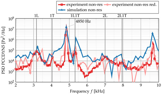
Figure 8.
Spectral power density of the pressure signals from the experiment and the simulation at non-resonant conditions.
It is speculated that the largest part of this discrepancy can be attributed to the thermal wall boundary condition in the simulations. All walls are treated as adiabatic walls, which oversimplifies the experimental environment where the walls have a cooling effect. Adiabatic walls also do not form a thermal boundary layer which has a damping effect on the acoustics. Another reason for the overestimation of the pressure amplitude might be the disregard of the flame–turbulence interaction. As the flame temperature and heat-release rate are lower in the presence of subgrid-scale turbulent fluctuations, the oscillation amplitude will also be reduced eventually. To a smaller extent, the difference in amplitude can also be explained by the different sample lengths of the experimental and the numerical signal. The amplitudes of the two signals agree better if the experimental signal length is reduced to the numerical signal length of 7.45 ms, and both signals are subjected to the same post-processing method for the power spectral density (cf. the light red curve in Figure 8).
It should also be noted that the non-resonant simulation is able to successfully capture the 2L mode of the chamber. This mode is only visible in the experimental spectrum for the non-resonant excitation and cannot be identified in the resonant signal. The same behavior is reproduced by the numerical simulation at resonant conditions, as will be shown in the later parts of the paper.
A detailed comparison of the eigenmode frequencies is given in Table 2.

Table 2.
Overview of the chamber mode eigenfrequencies for the different non-resonant simulation cases. The non-resonant experimental eigenfrequencies are also shown for comparison. All frequencies are given in Hertz.
All eigenmode frequencies for the non-resonant condition agree well with experimental results at Hz. The maximum error in frequency is obtained for the PSD results of the 2L mode with 2.1%.
Figure 9 shows the DMD eigenmode shapes of the non-resonant BKH simulation. The 2L1T mode has been omitted in favor of the 2L mode.
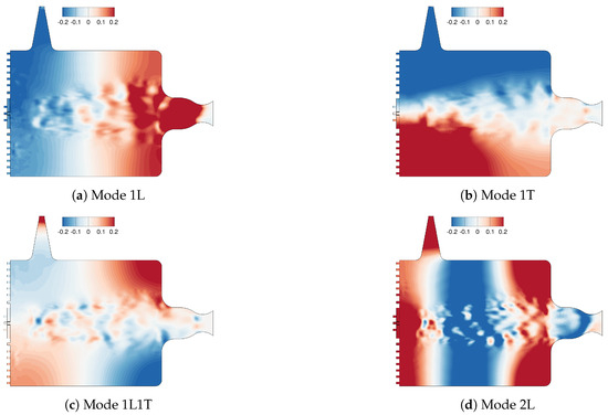
Figure 9.
DMD eigenmodes obtained from the non-resonant simulation of BKH.
DMD results for the excitation at 4850 Hz are corrupted by noise due to the relatively short length of the input signal. However, the overall mode shapes agree very well with the Helmholtz modes from the steady-state simulation in Figure 7. One notices, however, a different shape for the 1L mode.
The 1L mode obtained from the non-resonant condition shows a vertical nodal line in contrast to the skewed nodal line of the Helmholtz mode. This suggests a different and more symmetric speed of sound field. In order to investigate this, Figure 10 compares the time-averaged temperature and speed of sound fields for the unexcited steady-state DES and the non-resonant simulation.
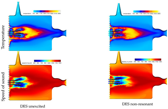
Figure 10.
Comparison of the time-averaged temperature and speed of sound field for the steady-state unexcited simulation and the non-resonant DES.
The comparison shows a more symmetrical distribution of the temperatures and the speed of sound. For the steady-state simulation, the cold inner region surrounding the dense oxygen cores is significantly larger for the lower injectors than for the top injectors (i.e., towards the siren). In contrast, the non-resonant simulation shows a very similar length for both inner regions. Another significant difference is the absence of a large hot gas pocket at the faceplate for the non-resonant simulation. Here, however, two smaller regions are formed at the faceplate at the position of the first row of secondary injection elements. The experimental shadowgraphy images in Figure 5 indicate an asymmetry in the flame distribution, giving a stronger recirculation of hot gases near the lower primary injectors, similar to the unexcited DES results. The amplitude of the off-resonance excited simulation is an order of magnitude greater than that in the experiment (see Figure 8), leaving the unexcited simulation with better comparability to the experimental off-resonance case. Therefore, the asymmetry in the upper and lower recirculation zones in the unexcited simulation (Figure 10 top left) can be said to be consistent with the experiment.
To further investigate the asymmetry in the speed of sound distribution, Figure 11 and Figure 12 show a temporal and spatial average of this value. Figure 11 shows the transversal speed of sound distribution. It is calculated by averaging over all mesh points in the axial direction in thin strips of thickness mm. Likewise, in Figure 12, all field values in thin vertical strips of thickness mm have been averaged.
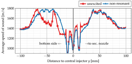
Figure 11.
Vertical (transversal) distribution of speed of sound. Each point y in this plot corresponds to a spatial average of all mesh points inside a thin strip between y and .
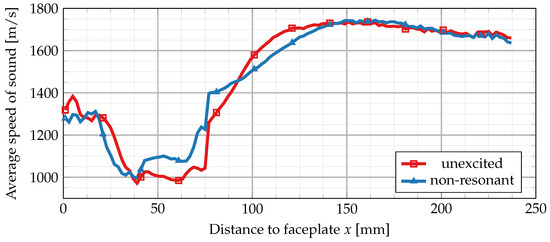
Figure 12.
Horizontal (axial) distribution of speed of sound. Each point x in this plot corresponds to a spatial average of all mesh points inside a thin strip between x and .
The comparison of the averaged speed of sound distribution in the transversal direction clearly shows an asymmetry for the unexcited steady-state simulation. The lower part of the combustion chamber is dominated by fluid of lower speed of sound compared to the upper part of the chamber. Near the secondary nozzle, both simulations agree very well. However, the lower part shows a much reduced speed of sound field that is dominated by a single maximum at —40 mm. This peak is most likely related to the hot gas zone mentioned before.
The presence of a low speed of sound region in the lower half of the chamber is responsible for the skewed nodal line in the 1L mode. By solving a one-dimensional version of the classical Helmholtz equation separately for the averaged sound speed distribution (averaged in transversal direction) in the upper and lower half of the chamber, one finds (a) a shift of the nodal line towards the faceplate, (b) a reduction in maximum amplitude near the faceplate and also (c) a reduction in the mode eigenfrequency. For the lower half, a frequency of 2889 Hz is obtained vs. 3120 Hz for the top half. Applying the 1D Helmholtz equation to the vertical speed of sound distribution (cf. Figure 11) separately for the unexcited and the non-resonant condition gives a slightly higher frequency for 1T mode and compares, therefore, more favorably with the experiment. The unexcited simulation gives a transversal 1T frequency of 3805 Hz vs. 3843 Hz for the non-resonant case.
Figure 12 shows the horizontal speed of sound distribution in the direction of the main flow.
The overall structure of the flow fields is very similar for both simulations. Small deviations remain in the central flame region between 20 mm and 80 mm. Here, the unexcited steady-state simulation shows a consistently lower speed of sound. Behind the central flame zone, the speed of sound distribution increases more steeply for the unexcited simulation. Further downstream towards the main nozzle, both simulations agree very well again. Near the faceplate at x = 0 mm, the unexcited steady-state simulation also shows a peak of higher speed of sound.
Regarding the comparison of the unexcited simulation results with the non-resonant excitation, it can be concluded that even though deviations between the numerical and experimental results for the lower frequency eigenmodes (namely 1L and 1T) persist, the overall agreement is quite good. The difference in 1L mode shape and frequency can be attributed to the skewed nodal line as the result of an asymmetric speed of sound distribution. The question remains, however, if the asymmetric speed of sound distribution would vanish for longer simulation time or if it is a persistent feature of the unexcited steady-state solution. If it was only an artifact of the limited length of the simulation, the unexcited steady-stimulation could serve as a useful and computationally cheap surrogate model for BKH in non-resonant conditions.
5.4. Results of a Virtual Bombing Test
A more direct way of determining the chamber eigenmodes is a virtual bomb test (impulse-response test) of the combustion chamber. Similar to bomb tests in real rocket engines, a strong pressure wave is generated inside the combustion chamber, and its temporal decay is recorded. This pressure wave excites all combustion chamber modes at the same time. Shortly after, all non-chamber-eigenmodes decay rapidly, and only true eigenmodes prevail. These eigenmodes can then be identified using standard signal-processing methods or more elaborate mode decomposition techniques, e.g., dynamic mode decomposition (DMD). For the virtual bomb test presented in this work, a pressure increase of 2.5 bar, shaped like a rectangular box, is added to the steady-state DES solution (cf. Figure 13) in the lower half of the combustion chamber. The specific shape of the initial pressure pulse is motivated by the desire to excite tangential as well as longitudinal modes. As we are only interested in the eigenmodes of the system, the exact shape of the initial pressure perturbation should be irrelevant. First numerical tests, however, showed that a purely horizontal pressure initialization excites longitudinal modes only marginally. Therefore, the initial pressure pulse has been modified to the box-like function shown in Figure 13 to excite all relevant modes.
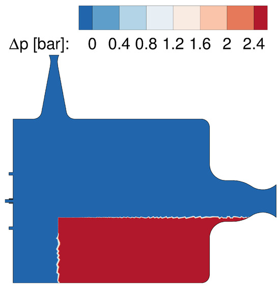
Figure 13.
Pressure initialization for the virtual bombing test.
The pressure signal of the decaying impulse-response is recorded at the position of the experimental sensor locations and converted into a power spectral density (PSD). The result is shown in Figure 14. The spectra for four different pressure sensors show three distinct peaks that are identified with the dominant eigenmodes 1T, 1L1T and 2L1T by DMD analysis (cf. Figure 15).
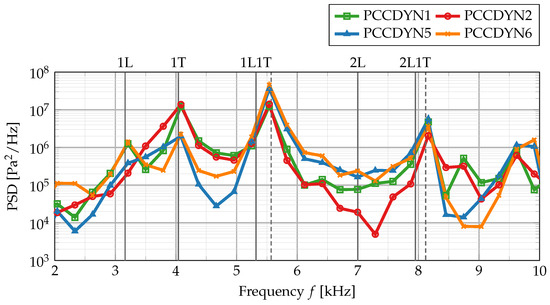
Figure 14.
Pressure spectral density from the virtual bombing detached-eddy simulation of BKH. The corresponding experimental eigenfrequencies are added as vertical lines (solid for non-resonant and dashed for resonant conditions) for comparison.
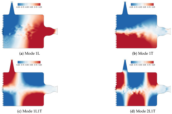
Figure 15.
DMD eigenmodes obtained from an impulse-response simulation of BKH.
In contrast to the non-resonant spectrum in Figure 8, the 1L mode is only visible in sensors PCCDYN1 and PCCDYN6 while being hidden for sensors PCCDYN2 and PCCDYN5 (which is used here in all spectra for comparison). The absence of the 1L mode in some of the sensors is most likely related to the skewed 1L nodal line that has been observed before in the Helmholtz modes (Figure 7). The same skewed nodal line also appears in the DMD mode shapes (Figure 15) from the virtual bombing test.
As the absence of the 2L mode has been observed experimentally also for the resonant simulation, the absence of the 1L mode is probably related to the skewed nodal line that has been observed before in the Helmholtz eigenmodes. Figure 15 shows the eigenmode shapes obtained with DMD for the virtual bomb test. These mode shapes agree well with the Helmholtz modes in Figure 7.
As the skewed nodal line is also found in this dataset, this suggests that it is a true feature of the underlying speed of sound field as opposed to being an artifact of the mode identification method. The skewed nodal line places the sensor PCCDYN5 (at the end of the top combustor wall near the nozzle entrance plane, cf. Figure 1) and also the sensor PCCDYN2 in a region of low amplitude. Due to the noisy environment inside the chamber, this probably reduces the signal-to-noise ratio for the 1L mode below the detection threshold in the PSD. The sensors PCCDYN1 and PCCDYN6 are placed well within regions of high 1L amplitude and, therefore, clearly detect this mode.
Comparing the eigenmode frequencies from the bombing simulation with the non-resonant mode results in Table 3 shows a shift of the higher mode eigenfrequencies (1L1T and 2L1T) towards higher values. This effect is also seen for the experimental data (see Figure 2) and has been explained [41] by a contraction of the flame leading to the modified speed of sound field.

Table 3.
Comparison of experimental and numerical chamber mode eigenfrequencies for the resonant case and the bombing simulation. All frequencies are given in Hertz.
It is surprising, at first glance, that the higher mode eigenfrequencies in the bombing test agree better with the resonant than with the non-resonant experimental results because the pressure disturbance was applied to the unexcited steady-state flow field. This indicates that the virtual bombing pressure perturbation is strong enough to change the flame shape and modify the underlying speed of sound distribution, which, in turn, changes the eigenmode frequencies. Even though this method was originally intended as a means to determine the non-resonant chamber eigenmodes, it is still very useful as an additional approach to estimate the frequency shift due to strong pressure excitation inside the chamber. The nonlinear interaction between the acoustic disturbance and the flame suggests that the initial choice of pressure pulse amplitude ( bar) is strong enough to change the eigenmode frequencies. A weaker disturbance might be necessary to still excite the combustion eigenmodes while not affecting the underlying speed of sound field. Such a method should then be able to predict the non-excited chamber modes.
5.5. Simulation Results with Resonant Siren Excitation
The last part of this work compares the flame response for non-resonant and resonant detached-eddy simulations of BKH. The non-resonant simulation has been discussed in the section before and uses an excitation frequency of = 4850 Hz. For the resonant simulation, the chamber’s 1T mode is directly excited by applying a siren frequency of = 4000 Hz.
Figure 16 compares the pressure signals for both simulations in the time domain. The non-resonant simulation is only weakly affected by the siren excitation, and the mean pressure increases initially to about 64 bar but then decays slowly back towards 62.5 bar.
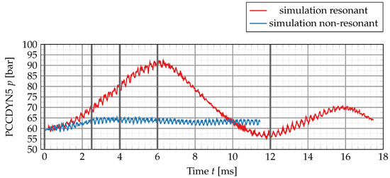
Figure 16.
Comparison of the pressure signal for the resonant and off-resonant condition. The grey vertical lines in the figure refer to specific points in time at which the dense LOx cores and the flame shapes will be compared. A visual representation of the dense LOx cores and the temperature field at the emphasized simulation times will be shown later in this section of the paper.
Under resonant conditions, however, the situation is fundamentally different. The oscillation amplitude increases strongly, and at the same time, the mean chamber pressure also increases. While the increase in oscillation amplitude is also seen in the experiment, no drift of the mean pressure is observed. During the first 6 ms of the simulation, the mean pressure rises up to about 90 bar and then drops back to about 58 bar.
This strong mean pressure increase has been observed before in single-flame URANS simulations [7] and is explained by an increased heat release due to additional mixing and a retraction of the flame towards the injection plane. As this strong increase in heat release cannot be sustained for longer times because the fuel and oxidizer are consumed at some point, the mean pressure drops again. At the current stage, the simulation length for the resonant excitation is not long enough to investigate if the simulation develops into a limit cycle. The chamber pressure continues to oscillate at a much longer time scale ( or ) compared to the siren excitation frequency and has not reached a steady value after 22 ms, even though the amplitude is strongly damped. The low-frequency mean pressure oscillation might be explained by the thermodynamic state at the injection plane and its interaction with the flame shape. A higher mean pressure leads to a higher propellant density (e.g., the inflow density of the primary hydrogen increases from 27.21 kg/m3 to 38.34 kg/m3 if the pressure is increased to 90 bar), and therefore, a lower inflow velocity. This change in inflow velocity modifies the flame shape and the length of the primary reaction zone, therefore affecting the total integrated heat release and the pressure in the chamber. By this feedback loop, a mean pressure increase can create an interaction pattern between the injection thermodynamics, the flame shape and the pressure response. Additionally, as the change in heat-release and pressure increase is coupled to the flame shape and size, this process is directly linked to the fluid-dynamical time scale which is significantly longer than the acoustical time scale, therefore exhibiting a lower frequency.
Due to the initial large pressure increase up to 90 bar, the validity of the simulation results between 3 ms and 10 ms is questionable as the flamelet table has been created for a fixed background pressure of 60 bar. After 12 ms, the maximum pressure amplitude is less than 70 bar, so that the error due to a different flamelet background pressure is acceptable with 21 K for the flamelet temperature and 20% for the maximum of heat release.
Another way of looking at the phenomenon of sudden pressure increase is to realize that the siren is instantaneously switched on in the numerical simulation, which is different from the experimental test procedure. During the experimental run, the siren frequency is linearly increased between the 1T and 1L1T mode at a rate of about 75 Hz/s. This is slow compared to a characteristic oscillation period in the combustion chamber, which is 0.25 ms at the 1T mode of 4000 Hz. In other words, when the external siren frequency is changed by 1 Hz, the chamber 1T eigenmode oscillates about 53 times. This suggests that the experimental flow field is always at a quasi steady-state regarding the siren excitation.
Figure 17 compares the resonant experimental spectrum with the simulation results from the non-resonant, the resonant and the virtual bombing simulation. The resonant spectrum shows frequency content at the correct location of the 1L, 1L1T and the 2L1T mode, even though these modes were not directly excited. The frequencies of the higher eigenmodes are also shifted towards higher values for the resonant simulation and agree well with the experimental results. Comparison of the amplitudes at resonant conditions shows a better agreement than at non-resonant conditions before. However, the numerical simulation still overestimates the experimental amplitudes in most parts of the spectrum which might be explained here again by a reduced acoustic damping and the omission of the flame–turbulence interaction.
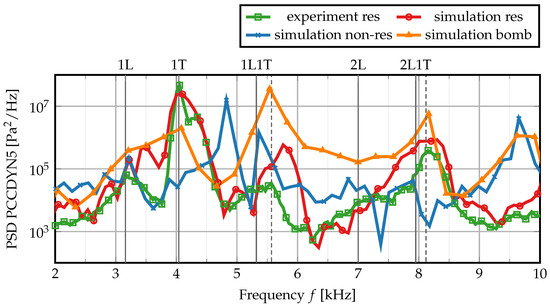
Figure 17.
Spectral power density of the pressure signals in the combustion chamber in resonant conditions and non-resonant conditions, as well as the virtual bombing simulation.
Resonant transversal excitation also has a strong influence on the dense oxygen cores (see Figure 18) and the surrounding flame shape, as has been shown in several publications [7,9,42] before. Under resonant transversal excitation, the cores retract, and they are flattened out perpendicular to the excitation direction. The top and bottom cores also bend outwards.
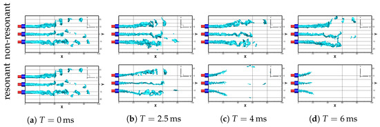
Figure 18.
Comparison of the dense LOx cores at different times of the resonant and off-resonance DES.
Resonant excitation dramatically changes the underlying flow field, as shown in Figure 19. The dense oxygen cores and, correspondingly, the flame length are reduced by about half. The region of hot gas downstream of the dense cores is also not visible anymore. After 12 ms, the flame seems to be even shorter in the central part of the combustion chamber compared to the outer flame between the oxygen cores and the first row of secondary injection elements.
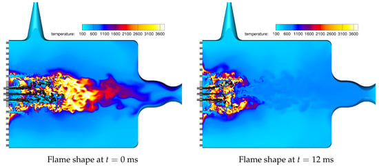
Figure 19.
Instantaneous temperature fields at 0 ms and 12 ms for the resonant BKH simulation. Density contours are displayed at = 100 kg/m3.
Even though the resonant simulation has not reached a steady mean pressure after 22 ms of physical simulation time and continues to show damped low frequency oscillations, the eigenmode frequencies agree well with the experimental results. In the same way as the virtual bombing simulation, the resonant excitation shifts the eigenmode frequencies towards higher values, therefore showing the same tendency as the experimental BKH results.
The biggest difficulty remains the correct determination of the eigenmode amplitudes from numerical simulations. For the resonant excitation condition, this requires the continuation of the simulation until the residual mean pressure oscillations are eventually damped out. To improve the predicting capabilities of simulations even further, one also needs to carefully examine the modeling assumptions (e.g., flame–turbulence interaction, boundary conditions, combustion model) to ensure that all physical mechanisms responsible for mode excitation and damping are well represented.
6. Discussion and Conclusions
This work presents the first detached-eddy simulation results for a new load point of combustion chamber H with both cryogenic oxygen and hydrogen. Three different numerical detached-eddy simulation setups are used to compare results from an unexcited steady-state simulation, a simulation at non-resonant conditions and one at the first transversal resonant condition.
Several modeling decisions have been made and are discussed in the paper. Turbulence–chemistry interaction is neglected based on the fact that the large-scale turbulent structures are resolved by the DES. The assumption of laminar chemistry effectively overestimates the heat-release rate and temperature of the flame and is believed to be one of the main causes for higher eigenmode amplitudes than in the experiment. Another point that should be addressed in a future study is the assumption of unity Lewis number. Even though H2/O2 flames at near-equilibrium only show a moderate influence of differential diffusion, this effect could be larger for the cryogenic hydrogen used in this work. This work also simulates only half of the domain and uses a symmetry boundary condition at its center. Even though the symmetry boundary does not influence the relevant eigenmodes of BKH because of its orientation, it can negatively affect the turbulent structures near the center of the chamber. This restriction will be lifted in future studies of BKH by doubling the computational domain and using the full geometry of the chamber.
We successfully used a combination of single-point pressure signal analysis and dynamic mode decomposition to compare numerical and experimental data and to identify the dominant mode shapes of the combustion chamber. It is shown that time-averaged simulation results from an unexcited steady-state simulation can be used to calculate the qualitatively correct Helmholtz eigenmode shapes and frequencies. Deviations in low frequency modes can be attributed to an asymmetric speed of sound distribution, which was investigated in detail.
Results from a non-resonant simulation predict the experimental eigenmode frequencies very well, even capturing a weak 2L mode which is also present in the non-resonant experimental spectrum. A systematic overestimation of the oscillation amplitude is explained by a reduced damping effect of the numerical setup due to the use of adiabatic wall boundary conditions.
Uncertainty in the experimental conditions reproduced in the simulations may also contribute to discrepancy in the comparison of resonance frequencies. The measured mass flow rates for the injectors are used as an input boundary condition for the simulation, and variation in ROF will influence the mean gas temperature and, thus, speed of sound and acoustic mode frequencies. It is difficult to quantify how the ±3% uncertainty in ROF translates to error in the frequencies of acoustic eigenmodes in the simulation, but it is expected to be of secondary significance.
Simulation results with resonant excitation show a good agreement with the experimental chamber eigenmode frequencies and correctly reproduce the shift of the frequency peaks to higher values. This effect is clearly visible in the experimental data for this work and has been observed before in different experiments with BKH. Results for the simulation in resonant conditions have not reached a limit cycle even after 22 ms, which is explained by the sudden activation of the siren in the simulation. This is in contrast to the experimental operation procedure where the siren is always switched on, and the flame has therefore reached a quasi steady-state regarding the siren excitation. The sudden activation in the simulation, however, causes a complex coupling between injector thermodynamics, chamber acoustics and flame response that leads to strongly damped low-frequency oscillations of the mean pressure. The results for a resonant excitation also confirm previous numerical and experimental findings on the strong influence of resonant transversal excitation on the length and shape of the dense LOx cores.
We also presented a DES-based virtual bombing method to directly obtain the resonant eigenmode frequencies based on an unexcited steady-state simulation. By placing a moderately strong pressure pulse of 2.5 bar inside the chamber and recording the subsequent decay of the oscillations, we were able to obtain a very good agreement with experimental resonant eigenmode frequencies. The results of this approach were somewhat surprising, as the pressure pulse was applied to the unexcited steady-state flow field. The pressure pulse, however, was strong enough to modify the underlying speed of sound field and, therefore, shift the mode frequencies to resonant values. It is argued that this approach could be utilized to also determine the non-resonant eigenmodes if a weaker pressure pulse was used.
The next step in this research is to include the acoustic properties of the injection elements and to investigate an acoustically coupled injector–combustor system. Previous experiments in a different model combustion chamber (Brennkammer D (BKD), see [43]) indicate that acoustic coupling between injector and combustor eigenmodes is a necessary criterion for the development of combustion instabilities. In this experiment, the second longitudinal oxygen injector mode had the same frequency as the first tangential combustion chamber mode. We therefore plan to further investigate this phenomenon numerically by reproducing a similar coupling scenario in BKH.
Author Contributions
Conceptualization, T.H.; methodology, T.H.; simulation software, T.H. and S.F.; validation, T.H. and S.F.; experimental investigation, J.H.; writing—original draft preparation, T.H.; writing—review and editing, all authors. All authors have read and agreed to the published version of the manuscript.
Funding
The authors gratefully acknowledge the Gauss Centre for Supercomputing e.V. (www.gauss-centre.eu) for funding this project pr27ji by providing computing time on the GCS Supercomputer SuperMUC-NG at Leibniz Supercomputing Centre (www.lrz.de). The present work was also conducted in the framework of the German Aerospace Center (DLR) project AMADEUS (Advanced Methods for Reusable Aerospace Vehicle Design using Artificial Intelligence and Interdisciplinary Numerical Simulation) focusing on the development of numerical methods for LOx-methane-based engine concepts in future space transportation systems. Financial support of the DLR Space Research Programmatic is highly appreciated.
Data Availability Statement
The datasets presented in this article are not readily available. Requests to access the datasets should be directed to the first author.
Conflicts of Interest
The authors declare no conflicts of interest.
Abbreviations
The following abbreviations are used in this manuscript:
| DLR | Deutsches Zentrum für Luft- und Raumfahrt (German Aerospace Center) |
| BKH | Brennkammer H (Combustion Chamber H) |
| URANS | Unsteady Reynolds-averaged Navier–Stokes equations |
| LES | Large-Eddy simulation |
| DES | Detached-Eddy simulation |
| ROF | Ratio of oxidizer-to-fuel (in mass fluxes) |
| TAU | DLR compressible flow solver code |
| PSD | Power spectral density |
| DMD | Dynamic mode decomposition |
| PCCDYN | Combustion chamber pressure () dynamic sensor |
References
- Culick, F.E.; Yang, V. Overview of combustion instabilities in liquid-propellant rocket engines. In Liquid Rocket Engine Combustion Instability; American Institute of Aeronautics and Astronautics: Reston, VA, USA, 1995; Volume 169, Chapter 1; pp. 3–37. [Google Scholar]
- Oefelein, J.C.; Yang, V. Comprehensive review of liquid-propellant combustion instabilities in F-1 engines. J. Propuls. Power 1993, 9, 657–677. [Google Scholar] [CrossRef]
- Wanhainen, J.; Parish, H.; Conrand, E. Effect of Propellant Injection Velocity on Screech in 20,000-Pound Hydrogen-Oxygen Rocket Engine; Technical Report NASA-TN-D-3373; National Aeronautics and Space Administration (NASA): Washington, DC, USA, 1966.
- Preclik, D.; Spagna, P. Low frequency and high frequency combustion oscillation phenomena inside a rocket combustion chamber fed by liquid or gaseous propellants. In Combustion Instabilities in Liquid-Fuelled Propulsion Systems; AGARD/CP-450; Advisory Group For Research and Development (AGARD); North Atlantic Treaty Organization (NATO): Neuilly-sur-Seine, France, 1989. [Google Scholar]
- Kurosu, A.; Yamanishi, N.; Tani, N.; Okita, K.; Ogawara, A.; Onga, T.; Atsumi, M. Study of Next Booster Engine LE-X in JAXA. In Proceedings of the 42nd AIAA/ASME/SAE/ASEE Joint Propulsion Conference, Sacramento, CA, USA, 9–12 July 2006; American Institute of Aeronautics and Astronautics: Reston, VA, USA, 2006; p. 4700. [Google Scholar] [CrossRef]
- Hardi, J. Experimental Investigation of High Frequency Combustion Instability in Cryogenic Oxygen-Hydrogen Rocket Engines. Ph.D. Thesis, School of Mechanical Engineering, University of Adelaide, Adelaide, Australia, 2012. [Google Scholar]
- Beinke, S.K. Analyses of Flame Response to Acoustic Forcing in a Rocket Combustor. Ph.D. Thesis, School of Mechanical Engineering, The University of Adelaide, Adelaide, Australia, 2017. [Google Scholar]
- Beinke, S.; Banuti, D.; Hardi, J.; Oschwald, M.; Dally, B. Modeling of a coaxial liquid oxygen/gaseous hydrogen injection element under high-frequency acoustic disturbances. Prog. Propuls. Phys. 2019, 11, 273–294. [Google Scholar]
- Morii, Y.; Beinke, S.; Hardi, J.; Shimizu, T.; Kawashima, H.; Oschwald, M. Dense core response to forced acoustic fields in oxygen-hydrogen rocket flames. Propuls. Power Res. 2020, 9, 197–215. [Google Scholar] [CrossRef]
- Conrad, E.; Bloomer, H.; Wanhainen, J.; Vincent, D. Liquid Rocket Engine Acoustic-Mode-Instability Studies at a Nominal Thrust of 20000 Pounds; Technical Report NASA-TN-D-4968; National Aeronautics and Space Administration (NASA): Washington, DC, USA, 1968.
- Wanhainen, J.; Feiler, C.; Morgan, C. Effect of Chamber Pressure, Flow per Element, and Contraction Ratio on Acoustic-Mode Instability in Hydrogen-Oxygen Rockets; Technical Report NASA-TN-D-4733; National Aeronautics and Space Administration (NASA): Washington, DC, USA, 1968.
- Wanhainen, J.P.; Hannum, N.P.; Russell, L.M. Evaluation of Speech Suppression Concepts in a 20,000 Pound Thrust Hydrogen Oxygen Rocket; Technical Report NASA-TM-X-1435; National Aeronautics and Space Administration (NASA): Washington, DC, USA, 1967.
- Gröning, S.; Hardi, J.; Suslov, D.; Oschwald, M. Influence of hydrogen temperature on the stability of a rocket engine combustor operated with hydrogen and oxygen. CEAS Space J. 2016, 9, 59–76. [Google Scholar] [CrossRef]
- Horchler, T. Skalenauflösende Simulation der Flammen-Akustik-Wechselwirkung bei Resonanter und Nicht-Resonanter Anregung in einer Experimental-Raketenbrennkammer. Ph.D. Thesis, Justus-Liebig-Universität Giessen, Gießen, Germany, 2022. [Google Scholar] [CrossRef]
- Hardi, J.S.; Beinke, S.K.; Oschwald, M.; Dally, B.B. Coupling of Cryogenic Oxygen–Hydrogen Flames to Longitudinal and Transverse Acoustic Instabilities. J. Propuls. Power 2014, 30, 991–1004. [Google Scholar] [CrossRef]
- Hardi, J.S.; Martinez, H.C.G.; Oschwald, M.; Dally, B.B. LOx Jet Atomization Under Transverse Acoustic Oscillations. J. Propuls. Power 2014, 30, 337–349. [Google Scholar] [CrossRef]
- Webster, S.; Hardi, J.; Oschwald, M. One-Dimensional Model Describing Eigenmode Frequency Shift During Transverse Excitation. In EUCASS Book Series—Advances in AeroSpace Sciences; EDP Sciences: Les Ulis, France, 2019; Volume 11, pp. 273–294. [Google Scholar] [CrossRef]
- Schwamborn, D.; Gerhold, T.; Heinrich, R. The DLR-TAU-Code: Recent Applications in Reasearch and Industry. In Proceedings of the European Conference on Computational Fluid Dynamics (ECCOMAS), Oslo, Norway, 5–9 June 2006. [Google Scholar]
- Karl, S. Numerical Investigation of a Generic Scramjet Configuration. Ph.D. Thesis, Fakultät für Maschinenwesen der Technischen Universität Dresden, Dresden, Germany, 2011. [Google Scholar]
- Thornber, B.; Mosedale, A.; Drikakis, D.; Youngs, D.; Williams, R. An improved reconstruction method for compressible flows with low Mach number features. J. Comput. Phys. 2008, 227, 4873–4894. [Google Scholar] [CrossRef]
- Rossow, C.C. Extension of a Compressible Code Toward the Incompressible Limit. AIAA J. 2003, 41, 2379–2386. [Google Scholar] [CrossRef]
- Löwe, J.; Probst, A.; Knopp, T.; Kessler, R. A Low-Dissipation Low-Dispersion Second-Order Scheme for Unstructured Finite-Volume Flow Solvers. In Proceedings of the 53rd AIAA Aerospace Sciences Meeting, Kissimmee, FL, USA, 5–9 January 2015; American Institute of Aeronautics and Astronautics: Reston, VA, USA, 2015; p. 0815. [Google Scholar] [CrossRef]
- Löwe, J.; Probst, A.; Knopp, T.; Kessler, R. Low-Dissipation Low-Dispersion Second-Order Scheme for Unstructured Finite Volume Flow Solvers. AIAA J. 2016, 54, 2961–2971. [Google Scholar] [CrossRef]
- Schumann, J.E.; Hannemann, V.; Hannemann, K. Investigation of Structured and Unstructured Grid Topology and Resolution Dependence for Scale-Resolving Simulations of Axisymmetric Detaching-Reattaching Shear Layers. In Progress in Hybrid RANS-LES Modelling; Springer International Publishing: New York, NY, USA, 2019; pp. 169–179. [Google Scholar] [CrossRef]
- Banuti, D.T.; Hannemann, V.; Hannemann, K.; Weigand, B. An efficient multi-fluid-mixing model for real gas reacting flows in liquid propellant rocket engines. Combust. Flame 2016, 168, 98–112. [Google Scholar] [CrossRef]
- Kim, S.K.; Choi, H.S.; Kim, Y. Thermodynamic modeling based on a generalized cubic equation of state for kerosene/LOx rocket combustion. Combust. Flame 2012, 159, 1351–1365. [Google Scholar] [CrossRef]
- Peters, N. Laminar diffusion flamelet models in non-premixed turbulent combustion. Prog. Energy Combust. Sci. 1984, 10, 319–339. [Google Scholar] [CrossRef]
- Ivancic, B.; Mayer, W. Time-and length scales of combustion in liquid rocket thrust chambers. J. Propuls. Power 2002, 18, 247–253. [Google Scholar] [CrossRef]
- Zong, N.; Guillaume, R.; Yang, V. A Flamelet Approach for Modeling of (LOX)/Methane Flames at Supercritical Pressures. In Proceedings of the 46th AIAA Aerospace Sciences Meeting and Exhibit, Reno, NV, USA, 7–10 January 2008. [Google Scholar] [CrossRef]
- Kim, S.K.; Kang, S.M.; Kim, Y.M. Flamelet modeling for combustion processes and NOx formation in the turbulent nonpremixed CO/H2/N2 jet flames. Combust. Sci. Technol. 2001, 168, 47–83. [Google Scholar] [CrossRef]
- Fechter, S.; Karl, S.; Hannemann, V.; Hannemann, K. Simulation of LOx/GH2 single coaxial injector at high pressure conditions. In Proceedings of the 53rd AIAA/SAE/ASEE Joint Propulsion Conference, Atlanta, GA, USA, 10–12 July 2017; American Institute of Aeronautics and Astronautics: Reston, VA, USA, 2017; p. 4765. [Google Scholar] [CrossRef]
- Ma, P.C.; Banuti, D.; Hickey, J.P.; Ihme, M. Numerical framework for transcritical real-fluid reacting flow simulations using the flamelet progress variable approach. In Proceedings of the 55th AIAA Aerospace Sciences Meeting, Grapevine, TX, USA, 9–13 January 2017; American Institute of Aeronautics and Astronautics: Reston, VA, USA, 2017. number 2017-0143. [Google Scholar] [CrossRef]
- Lacaze, G.; Oefelein, J.C. A non-premixed combustion model based on flame structure analysis at supercritical pressures. Combust. Flame 2012, 159, 2087–2103. [Google Scholar] [CrossRef]
- Suslov, D.I.; Hardi, J.S.; Oschwald, M. Full-length visualisation of liquid oxygen disintegration in a single injector sub-scale rocket combustor. Aerosp. Sci. Technol. 2019, 86, 444–454. [Google Scholar] [CrossRef]
- Ruiz, A.M.; Lacaze, G.; Oefelein, J.C.; Mari, R.; Cuenot, B.; Selle, L.; Poinsot, T. Numerical Benchmark for High-Reynolds-Number Supercritical Flows with Large Density Gradients. AIAA J. 2016, 54, 1445–1460. [Google Scholar] [CrossRef]
- Welch, P. The use of fast Fourier transform for the estimation of power spectra: A method based on time averaging over short, modified periodograms. IEEE Trans. Audio Electroacoust. 1967, 15, 70–73. [Google Scholar] [CrossRef]
- Jovanović, M.R.; Schmid, P.J.; Nichols, J.W. Sparsity-promoting dynamic mode decomposition. Phys. Fluids 2014, 26, 024103. [Google Scholar] [CrossRef]
- Tonti, F.; Perovšek, J.; Usandivaras, J.Z.; Karl, S.; Hardi, J.S.; Morii, Y.; Oschwald, M. Obtaining pseudo-OH* radiation images from CFD solutions of transcritical flames. Combust. Flame 2021, 233, 111614. [Google Scholar] [CrossRef]
- Skudrzyk, E. The Foundations of Acoustics; Springer: Vienna, Austria, 1971. [Google Scholar] [CrossRef]
- Alnæs, M.S.; Blechta, J.; Hake, J.; Johansson, A.; Kehlet, B.; Logg, A.; Richardson, C.; Ring, J.; Rognes, M.E.; Wells, G.N. The FEniCS Project, Version 1.5; Archive of Numerical Software: Heidelberg, Germany, 2015; Volume 3. [CrossRef]
- Webster, S.C.L. Analysis of Pressure Dynamics, Forced Excitation and Damping in a High Pressure LOX/H2 Combustor. Ph.D. Thesis, Rheinisch-Westfälische Technische Hochschule (RWTH), Aachen, Germany, 2016. [Google Scholar]
- Hakim, L.; Schmitt, T.; Ducruix, S.; Candel, S. Dynamics of a transcritical coaxial flame under a high-frequency transverse acoustic forcing: Influence of the modulation frequency on the flame response. Combust. Flame 2015, 162, 3482–3502. [Google Scholar] [CrossRef]
- Gröning, S.; Hardi, J.S.; Suslov, D.; Oschwald, M. Injector-Driven Combustion Instabilities in a Hydrogen/Oxygen Rocket Combustor. J. Propuls. Power 2016, 32, 560–573. [Google Scholar] [CrossRef]
Disclaimer/Publisher’s Note: The statements, opinions and data contained in all publications are solely those of the individual author(s) and contributor(s) and not of MDPI and/or the editor(s). MDPI and/or the editor(s) disclaim responsibility for any injury to people or property resulting from any ideas, methods, instructions or products referred to in the content. |
© 2024 by the authors. Licensee MDPI, Basel, Switzerland. This article is an open access article distributed under the terms and conditions of the Creative Commons Attribution (CC BY) license (https://creativecommons.org/licenses/by/4.0/).