Abstract
Conventional forward bleed slots reduce the hypersonic inlet starting Mach number but suffer from excessive flow leakage after restart. This paper proposes a novel reverse bleed slot design method for curved axisymmetric inlets of a solid-fuel scramjet. Leveraging the Kantrowitz criterion and detailed flow analysis, the method optimizes bleed slot placement, number, area, and angle. Results show superior aerodynamic performance by placing slots in the non-starting region of the internal compression section, considering both unstarted flow and separation bubble dynamics during restart. Each bleed slot area is calculated successively down-stream based on the Kantrowitz criterion. Finally, the effects of bleed slot angle have been extensively studied. The key inlet performance reaches its optimum at a slot angle of approximately 130°, achieving a significant reduction in the starting Mach number (from 4.80 to 3.65) and a 50% decrease in bleed flow rate compared to the forward slot design. This method demonstrates its feasibility and effectiveness, enabling substantial improvement in inlet starting performance with minimal flow loss.
1. Introduction
Solid-fuel scramjets offer a compelling combination of advantages: high specific impulse, high thrust-to-weight ratio, simple and compact design, rapid response, high reliability, and maneuverability [1,2,3]. These unique advantages make them highly attractive for a wide range of hypersonic propulsion applications, particularly in weapon systems. The allure of these capabilities was further bolstered by the successful concept demonstration in the 1980s by Witt et al. [4], which subsequently ignited extensive and meticulous research efforts in this field [5,6].
As a pivotal component of solid-fuel scramjet engines, the hypersonic inlet plays a critical role. It ensures the downstream combustion chamber receives a stable, high-quality, and combustion-ready airflow [7]. Notably, successful restart remains a critical design challenge for hypersonic inlets. Restart refers to the ability of the inlet to recover flow and maintain normal operation after temporary interruption or disturbance. The Mach number of the inlet entering the started condition from the unstarted condition, that is, the starting Mach number, represents its starting performance, which directly affects the normal operation of the engine and even the aircraft [8,9]. As the operating range of the inlet widens, the selection of the internal contraction ratio faces an intrinsic conflict between the requirement for high compression efficiency and flow capture capability and the requirement for good starting capability [10,11,12]. To address this issue, numerous researchers have conducted extensive studies, primarily focusing on variable geometry designs and flow control techniques. However, the introduction of adjustment mechanisms poses challenges in control, connection, and sealing, resulting in increased weight and decreased reliability [13,14,15]. Therefore, for solid-fuel scramjet engines, the preferred propulsion system for weapons—simpler inlet designs that avoid variable geometry structures—is recommended.
Numerous studies have demonstrated that the shockwave/boundary layer interaction is the key limiting factor of the starting capability of inlets. Therefore, many researchers have proposed the use of boundary layer suction as a simple and effective method [16,17,18]. Schulte et al. [19] conducted experimental studies and found that suctioning the boundary layer can effectively reduce the size of the separation region within the inlet, significantly improving the starting performance. Syberg et al. [20] provided specific steps for controlling the development of the boundary layer and identified that the bleed system is most effective when positioned at locations with high adverse pressure gradients. Fujimoto et al. [21] demonstrated that the bleed at the internal compression section can effectively improve the inlet’s starting performance and reduce shockwave/boundary layer interactions. Hamed et al. [22] studied the detailed effects of the bleed slot wave system on internal flow. Zhang [23] investigated different shock arrangements of a high internal compression ratio inlet and achieved a low Mach number restart with a 3% bleed loss. These widely used slots or holes are placed facing the incoming flow direction, and such designs face the problem of excessive flow loss after inlet restart, leading to reduced engine thrust and increased spillage drag. Jin et al. [24] proposed a promising reverse bleed slot scheme for traditional two-dimensional three-wedge inlets, where the bleed slot is placed facing away from the incoming flow, significantly reducing the spillage flow after restart. However, their calculation method for the reverse bleed slot area is the same as that for conventional forward bleed slots, determined from the Kantrowitz criterion [19,25] along the incoming flow direction, resulting in an oversized slot. Additionally, the selection of the reverse bleed slot’s location is mainly based on the reflection point of the lip shock at low Mach numbers, which is not satisfactory. In general, there is a lack of comprehensive understanding of the mechanism of the reverse bleed slot’s aerodynamic function, and the selection of design parameters relies mainly on parametric studies without sufficient theoretical guidance.
Traditional axisymmetric inlets generate compression from oblique shocks of multi-stage cones [26,27,28], and they suffer from excessive external compression length and significant performance degradation at off-design points. To address these issues, in recent years, Zhang et al. [29,30,31] proposed a curved centrebody shock compression method with good results. Therefore, building on the aforementioned research, this study proposes a novel design methodology for a curved axisymmetric hypersonic inlet with a reverse bleed slot in the solid-fuel scramjet. The approach is based on a Mach number-controllable curved surface compression axisymmetric inlet and combines the Kantrowitz criterion with the inlet’s flow field characteristics. The objective is to further improve the starting performance while minimizing flow losses and maintaining compression efficiency. By conducting numerical simulations and design parameter studies, such as the position, number, area, and angle of the reverse bleed slot, their impact on the inlet’s performance is evaluated. This analysis aims to reveal the aerodynamic control mechanism of the reverse bleed slot and provide valuable theoretical guidance for the optimal design of reverse bleed systems in hypersonic inlets.
2. Design and Analysis of the Reference Inlet
2.1. Design of the Reference Inlet
The external compression section of the axisymmetric reference inlet is designed using an inverse design method based on a target arctangent Mach number distribution [32]. To achieve a low lip shock strength and prevent shoulder separation, the upper and lower surfaces of the internal compression section employ smooth circular arcs for a seamless transition. Based on a parametric study, a set of design parameters with superior performance was selected, including an isolator section length of 7 times the throat height (as shown in Figure 1). Table 1 provides the specific parameters of the inlet. To achieve superior overall performance compared to conventional fixed-geometry inlets, the internal contraction ratio is set to a significantly higher value of 1.71.
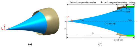
Figure 1.
Configuration of the reference inlet. (a) Three-dimensional configuration. (b) Geometric parameter definition.

Table 1.
Parameters of the reference inlet.
2.2. Numerical Calculation Method
2.2.1. Numerical Details
A commercial computational fluid dynamics (CFDs) software, FLUENT 15.0, utilizes a finite volume method solver for the Navier–Stokes (N-S) equations. The solver employs the advection upstream splitting method (AUSM) [33] for the convective flux scheme and the SST k-ω turbulence model [34,35,36]. Polynomial fitting is used for specific heat, and the Sutherland formula is used for the viscosity calculation. Convergence is considered achieved when each residual decreases by at least three orders of magnitude, and mass along the flow path is conserved. Table 2 presents the specific inflow parameters for the simulations, including the inflow Mach number (Ma), flight altitude (H0), static pressure (p0), and static temperature (T0). The starting Mach number (Mas) is defined as the minimum inflow Mach number at which the inlet can successfully restart from an unstarted condition using a quasi-steady process. This process involves progressively increasing the inflow Mach number in steps of 0.05 until a stable restart is achieved.

Table 2.
Different inflow conditions.
Figure 2 provides the structured grids and boundary conditions for the two-dimensional axisymmetric inlet. Considering the presence of shock/boundary layer interactions in the hypersonic inlet, the grid is refined near the wall and in regions requiring focus, such as near the cowl and in the internal compression section. The boundary conditions selected for the computation include pressure far field, pressure outlet, non-slip adiabatic wall, and axis. Due to the complex flow within the slot, the grid near the slot is also refined. The minimum grid spacing is set to 1.0 × 10⁻³ mm with a growth rate of 1.2, ensuring that the wall y+ value near the bleed hole is approximately 1.0. The outlet of the slot is set as the pressure outlet; its pressure is set to the same as the inflow static pressure since the outlet is connected to the low-pressure region on the air vehicle surface.
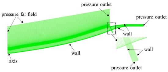
Figure 2.
Grid of computational domain.
2.2.2. Turbulence Model Validation
- (1)
- Validation of Inlet Computational Examples
To verify the accuracy of the numerical method employed in this study, a numerical simulation is conducted on a two-dimensional hypersonic inlet model (Figure 3) from the Aachen Jet Propulsion Laboratory, as described in reference [37]. The model inlet operates at a freestream Mach number of 2.41, a total pressure of 540 kPa, and a total temperature of 305 K for an isolator length of l = 79.3 mm. The experimental schlieren image in Figure 4 reveals the flow expanding along the corner (point B) of the compression ramp, visualized by the dark region. Slightly downstream, the impinging lip shock (point A) on the ramp induces a small separation of the boundary layer (point C). The corresponding separation and reattachment shocks are evident as two lines divided by another expansion region. An additional primary shock, induced by the cowl deflection angle (point D), intersects the separation and reattachment shocks, reflects off the ramp, and impinges nearly at the same location as the reattachment shock on the cowl surface (point G). Downstream, the repeatedly reflected shocks progressively weaken (points H, J, and K). An expansion also occurs at point I. The numerical results demonstrate good agreement with the experimental schlieren image, accurately capturing the wave structures and separation within the inlet. The x-direction coordinates of the corresponding points also show a close match.
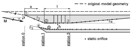
Figure 3.
Main dimension diagram of the inlet.
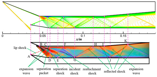
Figure 4.
Comparison of the Mach number contour lines of the computation (top) and the schlieren image (bottom) without throttling.
Furthermore, the pressure distributions on the ramp and cowl surface (Figure 5 and Figure 6) enable a more quantitative comparison between numerical and experimental results. A discrepancy exists in the ramp pressure distribution within the expansion region, leading to separation. The experimentally observed separation appears larger than predicted. Consequently, the separation shock is stronger and impinges upstream of the measured location (point E) on the cowl surface, exhibiting a difference of 7 mm. Despite this discrepancy, the overall agreement between simulation and experiment remains favorable. These findings substantiate the accuracy of the numerical method employed in this study, validating its suitability for this investigation.
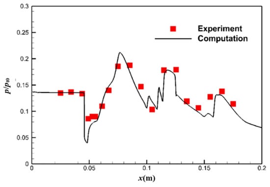
Figure 5.
Comparison of pressure distribution for the ramp without throttling.
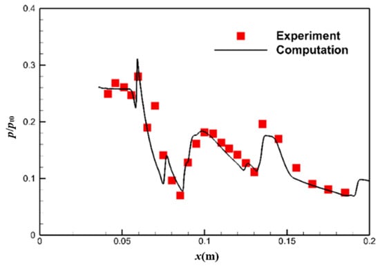
Figure 6.
Comparison of pressure distribution for the cowl surface without throttling.
- (2)
- Validation of Bleed Slot Computational Examples
To validate the effectiveness of the numerical simulation method for bleed slot flow, a comparison is conducted between the numerical computations and the experimental results reported in reference [38]. For the simulation, a single-hole test article is selected, featuring a diameter of 6.350 mm and a depth-to-diameter ratio of 0.250, as shown in Figure 7. A structured grid is meticulously generated and refined in the bleed hole region, with a minimum grid spacing set at 1.0 × 10⁻³ mm and a growth rate of 1.2. This configuration ensures that the wall y+ value near the bleed hole approximates 1.0. The convergence criterion is rigorously defined, ensuring that the discrepancy in the inflow and outflow mass fluxes remains within 10−3.
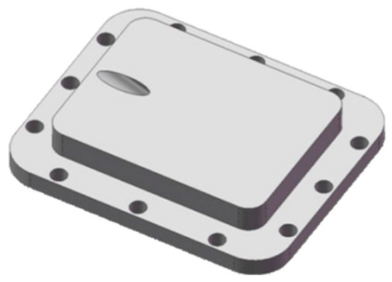
Figure 7.
Single-hole test article [38].
The sonic flow coefficient of the bleed hole, φb, is defined as [39]:
where mb is the actual bleed mass flow rate, and msonic denotes the sonic bleed mass flow rate. The sonic bleed mass flow rate is given by:
in this equation, Pt and Tt are the inflow total pressure and temperature, respectively, γ is the specific heat ratio, A is the area of the bleed hole, and R is the specific gas constant.
Two typical bleed holes with angles of 55° and 90° were selected to compare the flow coefficient (φb) as a function of the bleed chamber pressure ratio (pb/pt) under Mach numbers 1.4, 1.7, and 2.5, as shown in Figure 8 [38]. The numerical simulation results of the flow coefficient show good overall agreement with the experimental values across both high and low-pressure ratio ranges, with an average error not exceeding 5.5%. This indicates that the simulation method used in this study is reliable and effective.
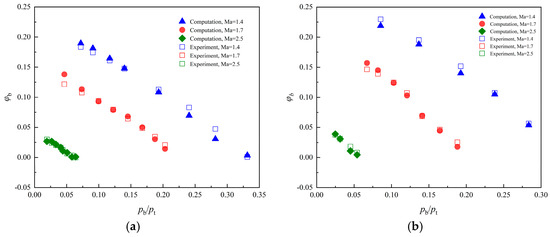
Figure 8.
The numerical computations are compared with the experimental results at different angles of bleed hole: (a) 90°; (b) 55°.
2.2.3. Grid Independence Verification
To ensure the accuracy and reliability of the numerical simulation results, a grid independence verification was performed by comparing the results obtained with different grid densities. The two-dimensional reference inlet was discretized using coarse (30,320 cells), medium (127,000 cells), and fine (434,400 cells) grids. Figure 9 presents the static pressure distribution along the centerbody surface at the design point of the reference inlet (Ma = 6.0) for each grid level. Table 3 presents the corresponding outlet area pressure ratio (pe/p0) and total pressure recovery coefficient (σe). Minimal differences are observed between the medium and fine grid results. This indicates that the medium grid resolution is sufficient to capture the flow physics accurately while maintaining computational efficiency. Consequently, subsequent calculations employed the medium grid.
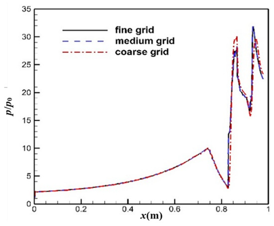
Figure 9.
Pressure distribution of the centrebody surface for refined grids.

Table 3.
Reference inlet’s outlet performance parameters in different grids.
2.3. Analysis of the Reference Inlet
Table 4 presents the overall performance parameters of the reference inlet for Mach numbers ranging from 4.0 to 7.0. These parameters include the flow coefficient (φ), total pressure recovery coefficient (σ), and pressure ratio (p/p0), with the subscript “th” denoting the throat section. Figure 10 illustrates the flow field of the reference inlet for typical Mach numbers. At the design point of Ma = 6.0, the curved incidence shock reaches the lip precisely, achieving a shock-on-lip condition. The flow coefficient, the outlet total pressure recovery coefficient, and the pressure ratio are 1.00, 0.53, and 23.3, respectively. However, at Ma = 7.0, the incident shock reaches the internal compression region, leading to increased total pressure losses, and the outlet total pressure recovery coefficient decreases to 0.36. At Ma = 4.0, the incidence shock remains curved, and the flow coefficient reaches a high value of 0.71 as the spillage area is relatively small. Additionally, for Mach numbers ranging from 4.0 to 7.0, the lip shock wave is relatively weak, and no significant separation is observed along the shoulder of the inlet. The reflected shocks within the isolator section are also relatively weak. The above results indicate that the axisymmetric reference inlet with curved compression surfaces exhibits high overall performance over a wide range of Mach numbers.

Table 4.
Overall performance of the reference inlet.
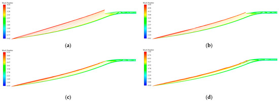
Figure 10.
Reference inlet flow field at typical Mach numbers: (a) Ma4.0; (b) Ma5.0; (c) Ma6.0; (d) Ma7.0.
The restart process of the reference inlet is illustrated in Figure 11. The initial unstarted flow field is calculated using a freestream Mach number of 2.8, and then the freestream Mach number is progressively increased. When the freestream Mach number reaches 3.0, a significant separation bubble forms near the entrance of the internal compression section. The maximum height of the separation bubble occurs at x/L = 0.755, resulting in the formation of an induced oblique shock ahead of the inlet lip, hindering the inlet from starting. At Ma = 3.9, the separation bubble shows minimal changes, with its maximum height and the midpoint of its length located at x/L = 0.764 and x/L = 0.782, respectively. As the freestream Mach number is increased to 4.7, the separation bubble reduces in size and moves towards the throat section. At Ma = 4.8, the separation bubble completely disappears, leading to a successful restart of the inlet; however, the starting Mach number is still high.
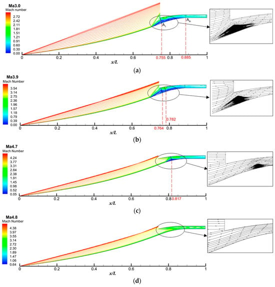
Figure 11.
Restart process of the reference inlet: (a) Ma = 3.0; (b) Ma = 3.9; (c) Ma = 4.7; (d) Ma = 4.8.
3. Design Method of Reverse Bleed Slot
Due to the reference inlet’s large internal contraction ratio, the starting Mach number is very high without employing any auxiliary measures. Previous research has demonstrated that forward bleed slots can reduce the starting Mach number, but they lead to excessive spillage after restart. To address this challenge of balancing starting Mach number and post-start spillage, this study proposes a novel design approach for reverse bleed slots based on the Kantrowitz criterion and the flow characteristics of the inlet. The specific design steps are outlined as follows:
Step 1: Divide the internal compression section of the reference inlet into “start region” and “non-start region” based on the Kantrowitz criterion.
Van Wie et al. [40] demonstrated a correlation between the starting Mach number and the internal contraction ratio, which aligns with the Kantrowitz criterion. The Kantrowitz criterion assumes a normal shock at the entrance of the internal compression section and calculates the isentropic flow area ratio based on choked flow conditions. For ideal gases, the Kantrowitz criterion is expressed by the following equation [25]:
where RcK is the maximum internal contraction ratio, A1 and Ma1 represent the area and Mach number at the entrance of the internal compression section, AthK represents the corresponding throat area, and γ is the specific heat ratio. According to the equation, as long as the actual physical throat area Ath is greater than or equal to AthK, the normal shock at the intake will be ingested, and the inlet will start.
Due to the scramjet engine’s operating range, a starting Mach number (Mas) of 3.5 is targeted for the inlet. However, as described earlier, the reference inlet cannot achieve restart at this Mach number. To optimize the design of bleed slots for improving starting characteristics, it is crucial to analyze the started inlet (Figure 12). The average Mach number (Mai) at each cross-section of the internal compression section is used. By substituting Mai for Ma1 in Equation (3), we can determine the maximum allowable internal contraction ratio (RcK) at each section. This information about RcK plays a vital role in defining limitations or influencing the effectiveness of bleed slot placement within the inlet. Equation (4) defines the internal contraction ratio (Rc) at each cross-section. This value helps identify two regions within the internal compression section: the non-start region and the start region. Locations with Rc exceeding RcK belong to the non-start region, while those with lower Rc fall within the start region. The bisection method, a numerical technique for finding boundaries, is applied from the A1 cross-section to efficiently determine the interface position (x/L) between these two regions. As illustrated in Figure 13, the interface is located at x/L = 0.831.
where Ai represents any cross-section area of the internal compression section, and Ath represents the throat area.

Figure 12.
Started flow field of the reference inlet at Ma3.5.
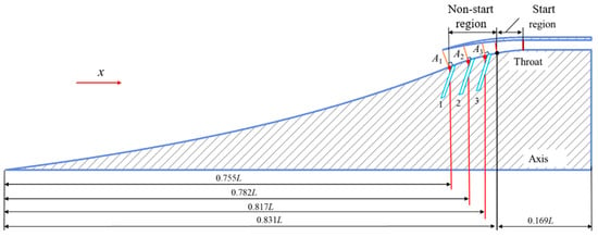
Figure 13.
Schematic diagram of the different regions and the location of the bleed slots for the internal compression section.
Step 2: Determine the location of the slots in the non-start region (x/L = 0.755–0.831) based on the flow characteristics during the restart process of the reference inlet.
The high starting Mach number of the reference inlet (up to 4.8) is attributed to a large separation bubble near the centerbody in the unstarted flow (Figure 11). This bubble acts as an ‘aerodynamic throat’ hindering restart. Eliminating it is critical. The non-start region identified earlier (x/L = 0.755–0.831) coincides with the area where the separation bubble is most prominent at low Mach numbers (Figure 11a,b). Therefore, the first bleed slot (Slot1) is placed at x/L = 0.755 to directly address this initial separation, as shown in Figure 13. As the separation bubble spans a wide axial range, a second bleed slot (Slot2) is positioned within its middle region (x/L = 0.782) to further reduce its size. Finally, since the separation bubble shrinks and moves backward with increasing freestream Mach number (Figure 11c), a third bleed slot (Slot3) is placed at its predicted tail location (x/L = 0.817). This strategic placement, informed by the restart analysis, aims to significantly reduce or potentially eliminate the separation bubble, thereby improving the inlet’s starting capability.
Step 3: Determine slot area from downstream using the Kantrowitz criterion.
After fixing the bleed slot locations (Figure 13), the corresponding Mach number (Mai) at each section is obtained from the reference inlet’s started flow field at Ma3.5 (Figure 12). This information is used in Equation (3) to determine the maximum allowable internal contraction ratio (RcK) for restart at each section. Within the non-start region, the actual internal contraction ratio (Rc) is higher than the allowable value RcK, as shown in Table 5. This indicates insufficient flow passage for restart. Introducing bleed slots effectively increases the throat area (acts like a bypass), lowering the actual contraction ratio (Rc). When Rc drops to the allowable value (RcK), the inlet can achieve restart.

Table 5.
The bleed slot section parameters.
Traditionally, the Kantrowitz criterion (Equation (5)) is used to calculate the total bleed slot area (Act) for each slot independently based on upstream conditions. However, in practice, a normal shock forms ahead of the first slot. This means that all three slots might be operational during restart. Consequently, the traditional method overestimates the total bleed slot area by simply adding the areas of each individual slot (Act1 + Act2 + Act3). This is because it does not account for the combined effect of all slots acting together. To address this overestimation, this study proposes calculating the actual slot area (Ac) for each bleed slot in the reverse direction, as shown in Figure 14, starting from the last slot (Slot3), as shown in Equation (6). This considers the cumulative effect of all downstream slots. Finally, Equation (7) is used to determine the slot width (dc), which is the distance between the opposing walls of the slot. The specific slot width values are provided in Table 5. Overall, this approach aims to optimize the bleed slot area by accounting for the interaction between multiple slots and the presence of the normal shockwave, ultimately reducing bleed loss.
where C is the circumference at the location of each bleed slot.
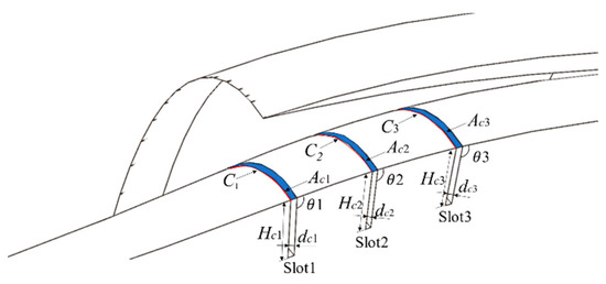
Figure 14.
Three-dimensional schematic of bleed slots and geometric parameter definitions.
Step 4: Obtain the optimal reverse slot angle through numerical simulations.
The text introduces the bleed slot angle (θ), as shown in Figure 14. It differentiates between conventional forward slots (θ ≤ 90°) and the reverse slots being used here (θ > 90°). The slot angle significantly impacts the inlet’s starting Mach number and bleed amount after restart. While there is no clear theoretical guideline for selecting this angle, some qualitative principles can be derived. Based on the reference inlet’s restart process (Figure 11a–c), the airflow near the centerbody within the separation bubble moves in the opposite direction compared to the main airflow. It is expected that reverse bleed slots (θ > 90°) will be more effective in eliminating this separation bubble compared to forward slots. While the angles of the three bleed slots could be different based on specific flow characteristics, this study assumes they are all equal (θ1 = θ2 = θ3) for simplicity. The slot depth (Hs) also influences performance. Here, a fixed depth of Hc1 = Hc2 = Hc3 = 20 mm is chosen, considering the centerbody thickness. The following section will use detailed numerical simulations to determine the optimal reverse bleed slot angle. Overall, this step emphasizes the importance of the bleed slot angle and the need for numerical simulations to find the optimal value for maximizing effectiveness in eliminating the separation bubble and improving starting performance.
Step 5: Evaluate and improve the reverse bleed slots based on numerical results.
Once the bleed slots are incorporated into the design, numerical simulations are conducted to assess the inlet’s performance in terms of starting Mach number, overflow, and overall performance. If the initial design with the chosen bleed slot parameters does not achieve the desired performance, the process enters an iterative stage. Here, the design parameters are adjusted based on the insights gained from analyzing the flow field structure within the bleed slots using the simulation results. The process of evaluating performance, analyzing flow fields, and adjusting design parameters is repeated until the desired performance requirements are met. This iterative approach ensures the bleed slot design is optimized for the specific scramjet inlet application. Overall, step 5 emphasizes the importance of using numerical simulations to evaluate and refine the bleed slot design for optimal performance.
4. Reverse Bleed Slot Angle Optimization
Following the determination of the location and area of each reverse bleed slot, this section explores the optimization of its angle (θ) to achieve optimal performance. Numerical simulation is employed to evaluate the inlet performance under different angle conditions and compare it with that of traditional forward bleed slots.
4.1. Starting Performance with Different Bleed Slot Angles
Figure 15 demonstrates that as the bleed slot angle θ increases, the inlet’s starting Mach number (Mas) decreases monotonically, especially in the range of 70° < θ < 110°, where Mas experiences a sharp decline. For forward bleed slots, Mas decreases to 4.05 at θ = 45° and is further reduced to 3.90 at θ = 90°. In contrast, the reverse bleed slot design achieves a minimum Mas of 3.65, translating to a 9.9% improvement in the starting Mach number compared to the forward bleed slot design. This indicates the superior effectiveness of the reverse bleed slot design in enhancing the inlet’s starting capability. However, it is notable that this minimum value deviates slightly from the target Mas value of 3.5. This mismatch can be attributed to the complexity of the actual flow field within the inlet. The non-uniformity of parameters across each section of the internal compression section can also contribute to this discrepancy. Further investigation into these factors may be necessary to optimize the design and achieve the target Mas value.
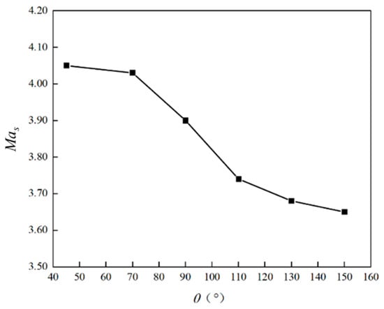
Figure 15.
Variation of starting Mach number with slot angle.
Table 6 and Figure 16 depict the relationship between the bleed slot angle (θ) and the relative bleed mass flow rate (ω), as expressed by Equation (3), for the case of an unstarted inlet. Specific data points are provided in Table 6, while the overall trend is visualized in Figure 16. As the freestream Mach number (Ma) increases, a near-linear rise in the relative bleed flow rate is observed. Notably, for a given freestream Mach number, the reverse bleed slot configuration (θ = 150°) demonstrates a significantly higher bleed mass flow rate compared to the forward bleed slot configuration (θ = 45°). At Ma = 3.4, the reverse bleed slot design exhibits an 18.7% increase in bleed flow rate compared to the forward bleed slot design. This observation suggests that the reverse bleed slot design offers superior effectiveness in promoting inlet restart.
herein, mc is the incoming capture flow rate, and mb is the total bleed flow rate from all three slots.

Table 6.
The relative bleed flow rate at different slot angles for the unstarted condition.
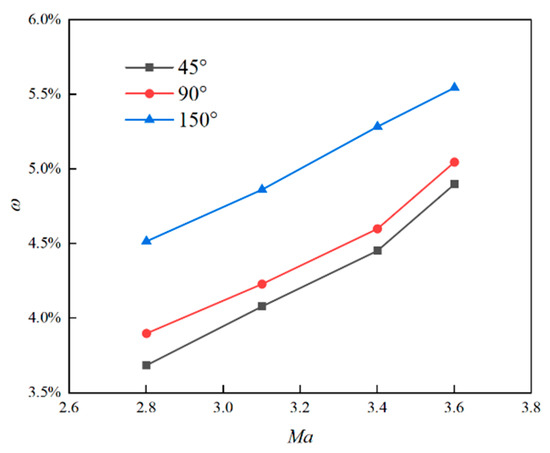
Figure 16.
Variation of relative bleed flow rate with Mach number for unstarted condition.
Figure 17 illustrates the streamlines of the unstarted flow field for representative forward and reverse bleed slot configurations at Ma3.4. The separated flow in the vicinity of the centerbody exhibits subsonic characteristics and opposes the main flow direction. Consequently, the reverse bleed slot configuration (θ > 90°) demonstrates greater effectiveness in discharging this low velocity flow (Figure 17a). In contrast, the forward bleed slot configurations (Figure 17b,c) necessitate flow redirection, resulting in a reduction in the effective flow area and an increase in total pressure loss. These observations contribute to the higher bleed flow rate achieved by the reverse bleed slot compared to the forward bleed slot during the inlet starting process.
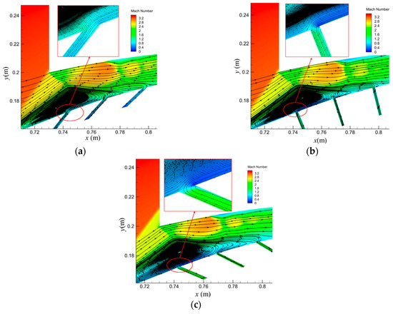
Figure 17.
Streamline plots of non-started flow field for typical slot angles at Ma3.4: (a) θ = 150°; (b) θ = 90°; (c) θ = 45°.
4.2. Bleed Flow Rate with Different Slot Angles
The bleed slot design concept inherently trades flow rate for a lower starting Mach number. Consequently, the relative bleed flow rate becomes a critical performance parameter. Figure 18 presents the variation of the relative bleed flow rate with respect to the freestream Mach number before and after inlet restart. Notably, for both forward and reverse bleed slot configurations, the total bleed flow rate observed in the unstarted condition is considerably higher compared to the started condition. Furthermore, the change in total bleed flow rate after restart is minimal. However, when compared to the forward bleed slot design, the reverse bleed slot configuration exhibits a lower bleed flow rate after inlet restart, thereby minimizing flow losses.
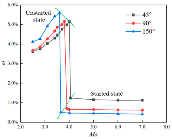
Figure 18.
Variation of bleed flow rate before and after starting with freestream Mach number.
As illustrated in Table 7 and Figure 19, the relative bleed flow rate (ω) of the started inlet exhibits a clear decreasing trend with increasing bleed slot angle (θ). Notably, for reverse bleed slot configurations (θ ≥ 110°), the relative bleed flow rate stabilizes at a near-constant value, reaching approximately 0.56% for Ma4.0 and 0.47% for Ma6.0. These values are roughly half of those observed for a typical forward bleed slot configuration (θ = 45°).

Table 7.
The relative bleed flow rate of the started inlet at different slot angles.
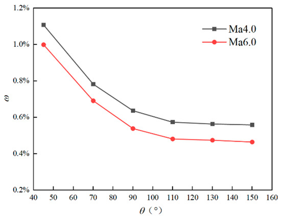
Figure 19.
Variation of relative bleed flow rate of the started inlet with slot angle.
To elucidate the physical mechanism behind the observed trend in bleed flow rate with respect to slot angle (Figure 19), an analysis of the restarted inlet flow field at the first bleed slot for Ma = 6.0 (Figure 20) is presented. The analysis reveals the following key observations: Forward bleed slot (θ = 45°): The flow exits smoothly through the slot without boundary layer separation. The supersonic nature of the flow within the slot contributes to a high bleed rate. Perpendicular bleed slot (θ = 90°): The bleed flow rate exhibits a decrease compared to the forward slot configuration. A small separation bubble forms near the corner of the slot, effectively creating an ‘aerodynamic throat’ that reduces the flow area and necessitates flow redirection. Reverse bleed slot (θ = 150°): This configuration demonstrates minimal flow loss. The effective deflection angle of the expansion fan is significantly smaller than the relative angle between the slot and the mainstream flow. This results in two key phenomena: First, a larger separation bubble forms on the windward side of the slot, leading to a smaller ‘aerodynamic throat’. Second, the deflected flow impinges on the slot surface, generating an oblique shock that redirects a portion of the flow back into the mainstream. This oblique shock also causes a decrease in total pressure, further contributing to the reduced bleed rate observed in this configuration.
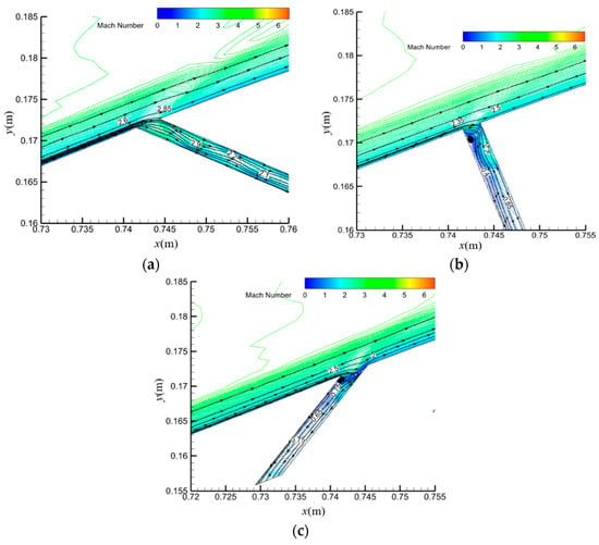
Figure 20.
Streamlines of started flow field near slot 1 at Ma6.0: (a) θ = 45°; (b) θ = 90°; (c) θ = 150°.
4.3. Overall Performance with Different Slot Angles
Figure 21 summarizes key performance parameters of the inlet at Ma = 6.0 for various bleed slot angles (θ). The bleed slot design effectively removes low-energy boundary layers, leading to a significant improvement in the total pressure recovery coefficient (Figure 21a) compared to the reference inlet. There is a 4.1% and 1.1% increase in total pressure recovery for angles of 45° and 130°, respectively. However, as the bleed slot angle (θ) increases, the oblique shocks generated at the slot inlets become stronger. This translates to a higher inlet pressure ratio (Figure 21b). A 130° angle yields a 2.7% increase compared to a 45° slot but a 1.0% increase relative to the reference inlet. This comes at the cost of higher shock losses and a reduction in downstream flow velocity. Additionally, the bleed slot design introduces a trade-off. While a decrease in bleed flow rate contributes to an increase in the inlet flow coefficient (Figure 21c), it compromises boundary layer removal effectiveness. Compared to the reference inlet, the mass flow coefficients are reduced by 1.2% and 0.5% for θ = 45° and 130°, respectively. These combined factors contribute to a larger separation bubble formed by the interaction between the lip shock and the centerbody boundary layer (Figure 22), further increasing total pressure loss. Consequently, for angles exceeding 146° (e.g., θ = 150°), the total pressure recovery coefficient even falls below the reference inlet, with a 0.3% decrease.
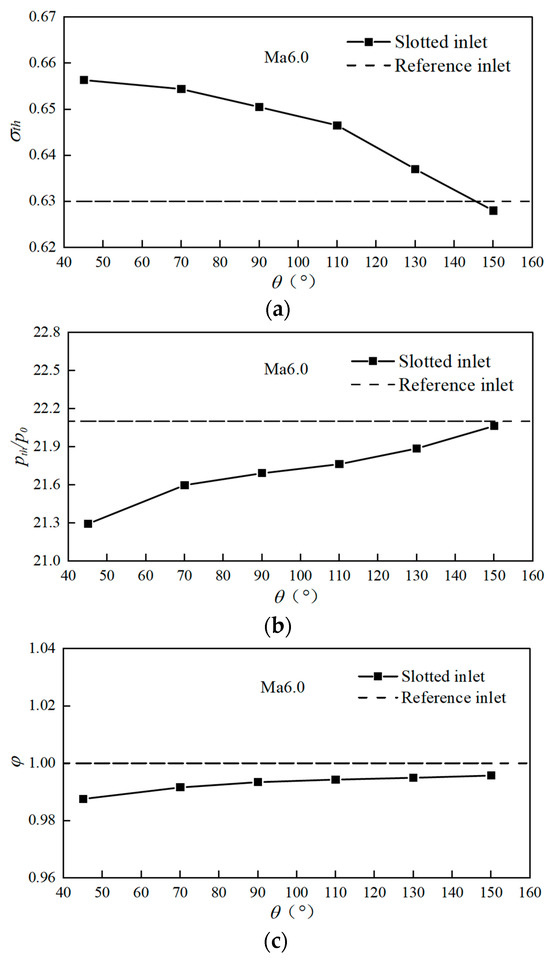
Figure 21.
Inlet key performance parameters for different slot angles at Ma6.0: (a) Total pressure recovery coefficient; (b) pressure ratio; (c) flow coefficient.
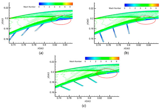
Figure 22.
Mach number contours of internal compression section with θ at Ma6.0: (a) θ = 150°; (b) θ = 90°; (c) θ = 45°.
In conclusion, the reverse bleed slot design has a minimal impact on inlet performance, significantly lower than the forward or perpendicular configurations. The optimal performance is achieved with a bleed slot angle of around 130°, where key parameters remain within 1.1% of the reference inlet values.
5. Conclusions
This study presents a novel reverse bleed slot design method for curved axisymmetric inlets, addressing the critical challenge of reducing the starting Mach number while minimizing flow losses. The proposed method, guided by the Kantrowitz criterion and detailed flow analysis, utilizes a reverse bleed slot configuration (θ = 130°) to achieve remarkable performance enhancements compared to conventional forward bleed slots. The key findings of this study are as follows:
- (1)
- The reverse bleed slot design significantly reduces the starting Mach number from 4.8 to 3.65, representing a substantial improvement in inlet operability.
- (2)
- The reverse bleed slot design exhibits a remarkably lower bleed flow rate, consuming only approximately 0.6% of the total flow, which is just half of that required by the forward configuration. This causes a significant increase in engine thrust.
- (3)
- The influence of the reverse bleed slot on key performance parameters of the inlet is found to be minimal, with variations remaining within a narrow range of 1.1% for θ = 130°. This demonstrates that the design effectively balances performance enhancement with minimal impact on overall inlet operation.
These combined findings strongly support the feasibility and effectiveness of the proposed reverse bleed slot design method. While the present study focuses on a specific inlet geometry, the underlying flow physics principles suggest the broad applicability of the conclusions to other inlets.
Author Contributions
Y.L.: conceptualization, methodology, software, validation, formal analysis, investigation, visualization, writing—original draft. D.S.: software, validation, visualization, writing—review and editing. X.T. and Y.Y.: validation, visualization, editing. X.L. and K.Z.: review and editing. All authors have read and agreed to the published version of the manuscript.
Funding
This research was funded by the Jiangxi Province Innovation Leading Talent Project (No. CK202206068), the Open Fund for the Key Laboratory of Aeroengine Thermal Environment and Thermal Structure (No. CEPE2022005), the Aeronautical Science Foundation of China (No. 20240012056001), and the Doctor Initial Fund Project of Nanchang Hangkong University (No. EA202006371).
Data Availability Statement
The datasets generated or analyzed during this study are available from the corresponding author upon reasonable request.
Conflicts of Interest
The authors declare no conflicts of interest.
Correction Statement
This article has been republished with a minor correction to the Funding statement. This change does not affect the scientific content of the article.
References
- Angus, W.J. An Investigation into the Performance Characteristics of a Solid Fuel Scramjet Propulsion Device; Naval Postgraduate School: Monterey, CA, USA, 1991. [Google Scholar]
- Evans, J.; Senior, W.; Gejji, R.; Slabaugh, C. Experimental characterization of a solid-fuel ramjet combustor at flight-relevant conditions. AIAA Pap. 2020, 2020, 3897. [Google Scholar]
- Zhao, X.; Xia, Z.; Ma, L. Research progress on solid-fueled scramjet. Chin. J. Aeronaut. 2022, 35, 398–415. [Google Scholar] [CrossRef]
- Witt, M. An Investigation into the Feasibility of Solid Fuel Dual Mode Ramjet and Scramjet Propulsion; Naval Postgraduate School: Monterey, CA, USA, 1989. [Google Scholar]
- Gany, A.; Netzer, A. Burning and flame holding characteristics of a miniature solid fuel ramjet combustor. J. Propuls. Power 1991, 7, 357–363. [Google Scholar]
- Pei, X.; Wu, Z.; Wei, Z. Numerical investigation on internal regressing shapes of solid-fuel scramjet combustor. J. Propuls. Power 2013, 29, 1041–1051. [Google Scholar] [CrossRef]
- Heiser, W.; Pratt, D.; Daley, D. Hypersonic Air-Breathing Propulsion; Education Series; AIAA: Washington DC, USA, 1994. [Google Scholar]
- Yu, H.; Guo, Y.; Yuan, X.; Wang, J. Flight/propulsion integrated control of over-under TBCC Engine Based on GA-LQR method. Aerospace 2022, 9, 621. [Google Scholar] [CrossRef]
- Wang, M.; Wang, Z.; Zhang, Y.; Cheng, D.; Tan, H.; Wang, K.; Gao, S. Control of Cowl Shock/Boundary Layer Interaction in Supersonic Inlet Based On Dynamic Vortex Generator. Aerospace 2023, 10, 729. [Google Scholar] [CrossRef]
- Wieting, A. Exploratory Study of Transient Upstart Phenomena in a Three-Dimensional Fixed-Geometry Scramjet Engine; NASA-TN-D-8156; NASA: Washington, DC, USA, 1976.
- Shimura, T.; Mitani, T.; Sakuranaka, N. Load oscillations caused by unstart of hypersonic wind tunnels and engines. J. Propuls. Power 1998, 14, 348–353. [Google Scholar] [CrossRef]
- Falempin, F.; Wendling, F.; Goldfeld, M. Experimental investigation of starting process for a variable geometry air inlet operating from Mach 2 to Mach 8. AIAA Pap. 2006, 2006, 4513. [Google Scholar]
- Bouchez, M.; Levine, V.; Davidenko, D. Airbreathing space launcher interest of a fully variable geometry propulsion system-Status. AIAA Pap. 1999, 1999, 2376. [Google Scholar]
- Huebner, L.; Rock, K.; Ruf, E. Hyper-X Flight Engine Ground Testing for Flight Risk Reduction. J. Spacecr. Rocket. 2012, 38, 844–852. [Google Scholar] [CrossRef]
- Li, Y.; Li, G.; Liu, X.; Ma, Y. Design of a curved axisymmetric variable geometry inlet with Mach number from 1.5 to 4.5. J. Rocket. Propuls. 2018, 44, 30–35. [Google Scholar]
- Liu, Y. Research on Adaptive Pressure Relief Control of Fixed-Geometry Hypersonic Inlet Working at Large Mach Number Rang; Nanjing University of Aeronautics and Astronautics: Nanjing, China, 2012. [Google Scholar]
- Harloff, G.; Smith, G. Supersonic-inlet boundary-layer bleed flow. AIAA J. 1996, 34, 778–785. [Google Scholar] [CrossRef]
- Molder, S.; Timofeev, E.; Tahir, R. Flow starting in high compression hypersonic air inlets by mass spillage. In Proceedings of the 40th AIAA/ASME/SAE/ASEE Joint Propulsion Conference and Exhibit, Fort Lauderdale, FL, USA, 11–14 July 2004; p. 4130. [Google Scholar]
- Schulte, D.; Henckels, A.; Wepler, U. Reduction of shock induced boundary layer separation in hypersonic inlets using bleed. Aerosp. Sci. Technol. 1998, 2, 231–239. [Google Scholar] [CrossRef]
- Syberg, J.; Koncsek, L. Bleed system design technology for supersonic inlets. J. Aircr. 1973, 10, 407–413. [Google Scholar] [CrossRef]
- Fujimoto, A.; Niwa, N.; Sawada, K. Numerical investigation of supersonic inlet with realistic bleed and bypass systems. J. Propuls. Power 1992, 8, 857–861. [Google Scholar] [CrossRef]
- Hamed, A.; Shih, S.; Yeuan, J. An investigation of shock/turbulent boundary layer bleed interactions. J. Propuls. Power 1992, 10, 79–87. [Google Scholar] [CrossRef]
- Zhang, X.; Yue, L.; Zhang, X. Shocks arrangement of ramp compression hypersonic inlet with high internal contraction ratio. J. Propuls. Technol. 2012, 33, 505–509. [Google Scholar]
- Jin, Z.; Zhang, K.; Liu, Y. Concept and experimental validation of adaptive pressure relief control for fixed geometry hypersonic inlets. ACAT Aerodyn. Sin. 2014, 32, 475–480. [Google Scholar]
- Kantrowitz, A.; Donaldson, C.D. Preliminary Investigation of Supersonic Diffusers; NACA TR-L5D20; National Advisory Committee for Aeronautics: Washington, DC, USA, 1945.
- Andrews, E.; Mackley, E. Analysis of Experimental Results of the Inlet for the NASA Hypersonic Research Engine Aerothermodynamics Integration Model; NASA/TM: Washington, DC, USA, 1976; p. 336.
- Zhang, Y.; Tan, H.; Zhuang, Y.; Wang, D.P. Morphing supersonic inlet with deforming air cell. J. Propuls. Power 2015, 31, 583–591. [Google Scholar] [CrossRef]
- Yuan, H.; Liu, F.; Wang, X.; Zhou, Z. Design and analysis of a supersonic axisymmetric inlet based on controllable bleed slots. Aerosp. Sci. Technol. 2020, 107, 106347. [Google Scholar] [CrossRef]
- Zhang, K. Review on curved compression technology of hypersonic inlet. J. Propuls. Technol. 2018, 39, 2227–2235. [Google Scholar]
- Li, Y.; Sun, D.; Wu, Z.; Zhang, K. Flow Coefficient and Starting Performance Prediction of Variable Geometry Curved Axisymmetric Inlet. Aerospace 2023, 10, 692. [Google Scholar] [CrossRef]
- Xiang, Y. Preliminary Research No Hypersonic Axisymmetric Curved Compression System; Nanjing University of Aeronautics and Astronautics: Nanjing, China, 2012. [Google Scholar]
- Li, Y.; Zhang, K.; Sun, D. Effect of suction on performance of inward turning inlet with rectangular-to-circular shape transition. Acta Aeronaut. Astronaut. Sin. 2016, 37, 3625–3633. [Google Scholar]
- Van Leer, B. Towards the ultimate conservative difference scheme. V. A. second order sequel to Godunov’s method. J. Comput. Phys. 1979, 32, 101–136. [Google Scholar] [CrossRef]
- Roya, C.J.; Blottner, F.G. Review and assessment of turbulence models for hypersonic flows. Prog. Aerosp. Sci. 2006, 42, 469–530. [Google Scholar] [CrossRef]
- Menter, F.R. Two-equation eddy-viscosity turbulence models for engineering applications. AIAA J. 1994, 32, 1598–1605. [Google Scholar] [CrossRef]
- Zeng, Y.; Wang, H.; Sun, B.; Wang, C.; Liu, X. SST turbulence model improvements: Review. Acta Aeronaut. Astronaut. Sin. 2023, 44, 027411. [Google Scholar]
- Reinartz, B.; Herrmann, C.; Ballmann, J. Aerodynamic performance analysis of a hypersonic inlet isolator using computation and experiment. J. Propuls. Power 2003, 19, 868–875. [Google Scholar] [CrossRef]
- Eichorn, M.; Barnhart, P.; Davis, D.; Vyas, M.; Slater, J. Effect of boundary-layer bleed hole inclination angle and scaling on flow coefficient behavior. AIAA Pap. 2013, 2013, 0424. [Google Scholar]
- Willis, B.P.; Davis, D.O.; Hingst, W.R. Flow coefficient behavior for boundary layer bleed holes and slots. AIAA Pap. 1995, 1995, 0031. [Google Scholar]
- Van Wie, D.; Kwok, F.; Walsh, R. Starting characteristics of supersonic inlets. In Proceedings of the 32nd Joint Propulsion Conference and Exhibit, Lake Buena Vista, FL, USA, 1–3 July 1996; p. 2914. [Google Scholar]
Disclaimer/Publisher’s Note: The statements, opinions and data contained in all publications are solely those of the individual author(s) and contributor(s) and not of MDPI and/or the editor(s). MDPI and/or the editor(s) disclaim responsibility for any injury to people or property resulting from any ideas, methods, instructions or products referred to in the content. |
© 2024 by the authors. Licensee MDPI, Basel, Switzerland. This article is an open access article distributed under the terms and conditions of the Creative Commons Attribution (CC BY) license (https://creativecommons.org/licenses/by/4.0/).