Article

Comparative Study of Numerical Schemes for Granular Combustion of Boron Potassium Nitrate

1
Department of Aerospace Engineering, Indian Institute of Technology Madras, Chennai 600036, India
2
Defence Research and Development Laboratory, Hyderabad 500053, India
*
Author to whom correspondence should be addressed.
Aerospace 2024, 11(4), 251; https://doi.org/10.3390/aerospace11040251
Submission received: 1 February 2024 / Revised: 10 March 2024 / Accepted: 18 March 2024 / Published: 23 March 2024
(This article belongs to the Special Issue Aerospace Combustion Engineering (2nd Edition))

Abstract

:
Multiple applications in aerospace utilize pyrotechnic charges for their operation, and these charges are predominantly in the form of granules. One of the most used charges is boron potassium nitrate (BPN), and the present study focuses on mathematically modeling granular combustion, its experimental recreation, and carrying out a comparative study on three upwind schemes for its numerical simulation. A customized version of the seven-equation compressible multifluid formulation is presented in this paper to model granular combustion mathematically. Three upwind schemes, namely HLLC, AUSM+-up, and HLLC-AUSM, are used for the numerical comparison. Utilizing these, an axisymmetric code is developed for the comparative study. To experimentally replicate granular combustion, granular BPN is fired in a closed bomb test facility, and the experimental pressure history is used for the numerical comparisons. The developed code can adequately predict the physics of granular combustion, and all three schemes are equally capable of numerical prediction.

1. Introduction

In the field of aerospace, numerous applications deploy pyrotechnic charges, namely pyrotechnic initiators, gas generators, airbags, ejection recovery systems, pyrotechnic fasteners, igniters in small solid rocket motors, decoy flares, ignition cartridges, etc. Metal oxidizers are commonly used compositions for these applications. Among compositions like zirconium potassium perchlorate, aluminum potassium perchlorate, and titanium aluminum potassium perchlorate, boron potassium nitrate (BPN) is the most widely used. BPN is thermally stable, suitable for rapid initiation, and stable in a vacuum, and its burn rates are almost independent of pressure. In all of these applications, BPN is used in granular form and is initiated by passing an electric current through a bridgewire. As the electric current passes, the bridgewire becomes heated and, in turn, heats the granules to their ignition temperature and produces hot combustion products. These hot combustion products flow into the remaining granular bed, heating and igniting it. During this process, a high-pressure gradient leads the ignition front to accelerate [1]. The operation of all the applications mentioned earlier is crucially decided by the granular combustion of BPN, which brings importance to the present study. In granular combustion, there are two main phases to model, viz., a solid phase and a gaseous phase. Due to the generation of very high pressures during the operation, both phases are assumed to be compressible. A closed bomb test facility is utilized to experimentally replicate granular combustion.
In 1976, Krier and Ghokale [2] published a benchmark paper on granular combustion, where they explained how to predict the pressure wave propagation and flame spread within the porous propellant charge. Kuo et al. [3] developed a theoretical model that describes flame propagation in a packed bed of granular propellant under confinement. Following these two major works, a series of numerical studies on granular combustion was carried out by Powers et al. [4], Gonthier and Powers [5,6], Bdzil et al. [7], and Saurel et al. [8], where they explained, in detail, various methods of modeling and solving the problem computationally. In all of these models, the volume fraction evolution was in non-conservation form, until 2017, when Saurel et al. [9] derived the same volume fraction evolution in conservation form. With this, the complete model is now in full conservation form. Davis and Kuo conducted experimental studies on the combustion of granular propellant beds [10]. In all of these studies, large propellant beds of ZPP, HMX, or M48 double-base propellants were used, while a granular bed of BPN was used for the present study. Han et al. [11] carried out both experimental and computational studies with a closed bomb, where the computational model used was the Eulerian–Lagrangian model, and Ulas et al. [12] carried out similar studies for a BPN-based pyrotechnic igniter using a 0-D unsteady model. In the present study, the complete physics of granular combustion is modeled. In the literature, compressible multiphase applications are numerically solved mainly by using either of the three upwind schemes, viz., HLLC [13,14], AUSM family [15], and a combination of the two, known as HLLC-AUSM [16,17]. Various studies using these schemes have been carried out in the literature, and comparative studies have been carried out within the same family of schemes. In the present study, two upwind schemes from different families and a combination of the two schemes are studied and compared for granular combustion.
In the study presented in this paper, the granular combustion of BPN is experimentally recreated through a closed bomb test, and an axisymmetric code is developed for the numerical prediction of granular combustion and the comparison of upwind schemes. A customized version of the seven-equation compressible multifluid formulation is curated to model the physics of granular combustion. This model is thermodynamically consistent and unconditionally hyperbolic and could accurately model the propagation of pressure, velocity, and density disturbances. The unstructured finite volume method is used for spatial discretization, and eSSPRK(4,3) is used for temporal discretization. The numerical flux schemes used are HLLC, AUSM+-up, and HLLC-AUSM. The code has been validated for an air–water shock tube and for shock interaction with a dense granular bed, and in this paper, it is used to carry out a comparative study for the granular combustion of BPN with three upwind schemes.

2. Closed Bomb Test

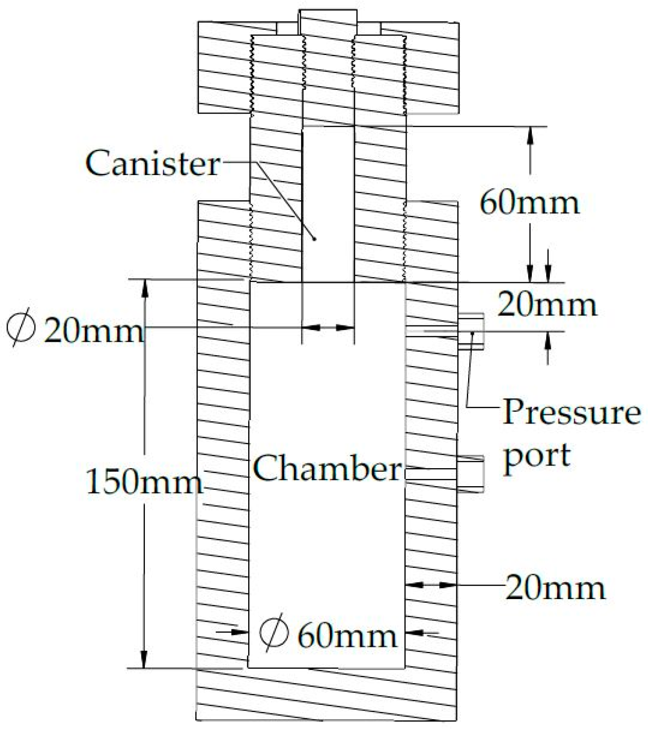
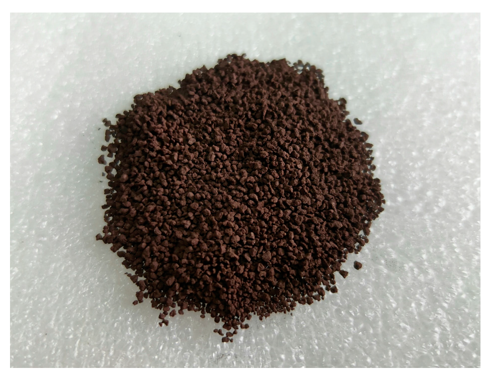
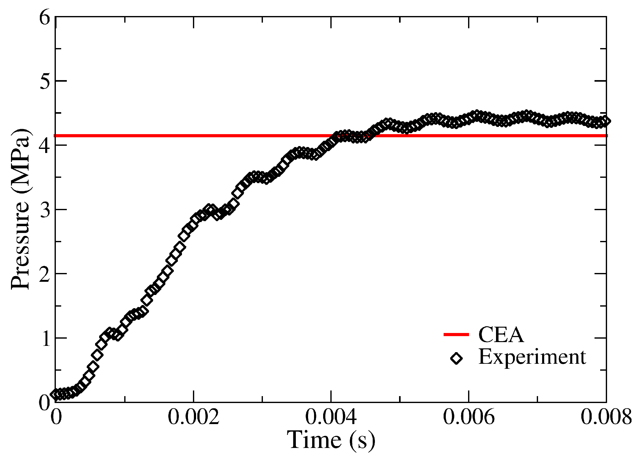
The phenomenon of granular combustion is experimentally replicated through a closed bomb test. The cylindrical test setup comprises a canister and chamber sections, as shown in Figure 1. The canister is 60 mm long with a 20 mm diameter, and the chamber is 150 mm long with a 60 mm diameter, as shown in Figure 2. Five grams of granular BPN is used for the test, and a sample is shown in Figure 3. The granular bed is loosely packed, placed in the canister section, and occupies 29 mm out of the 60 mm. Beneath the granular bed is a bridgewire through which an electric current is passed, and the bottom of the bed becomes ignited. Nichrome wire is used as the bridgewire, and a 30 A current passes through it. The pressure build-up is measured at 20 mm from the chamber head end through an absolute pressure sensor. The sensor specifications are mentioned in Table 1. The pressure sensor data are fed through a data acquisition module (model: NI9239) and recorded using the NI Signal Express® software (version 2015) at 25 kHz. The recorded voltage readings are then corrected for residual unbalance and converted into corresponding pressure values. Through a particle size analysis, the diameter of the granular BPN used is determined to be 897 µm. The burn rate for granular BPN is experimentally determined to be 19.759P0.1888 mm/s with pressure in bar. The density is measured and found to be 2000 kg/m3. Using the NASA CEA code [18], a constant volume (uv problem) chemical equilibrium analysis is carried out for 5 g of BPN, and the peak pressure predicted is 4.147 MPa with a flame temperature of 3011.5 K, and the combustion product properties are obtained. The experimental pressure–time curve for granular BPN and the CEA predicted peak pressure are shown in Figure 4.

3. Compressible Multifluid Formulation for Granular Combustion

In granular combustion, there are mainly two phases, i.e., a gaseous phase and a solid phase. The pressure generated during the operation of actual systems is very high. Hence, it is assumed that both phases are compressible and are governed by the corresponding equation of states, namely the ideal gas equation of state for the gaseous phase and the stiffened gas equation of state for the solid phase. To model the physics of granular combustion, the two-phase compressible multifluid formulation explained by Saurel et al. [9] is customized for granular combustion. The formulation is a full non-equilibrium model and is a modified version of the seven-equation model. The model consists of a set of balance equations, viz., mass, momentum, and energy for each phase, which are the first eight equations. The solid volume fraction evolution is the ninth equation. The first nine equations used for the modeling are explained in detail by Saurel et al. [9]. The following equations are incorporated into these equations to curate the model for granular combustion, viz., the conservation of the number density of granules, the condensed phase combustion products formed, and the gas species equation to account for the initial air in the system and the gaseous combustion products created. The tenth equation is the evolution of number density per unit volume of granules [19]. This equation ensures the number of granules is conserved by assuming that the granules burn to a small cutoff radius and remain at that cutoff radius. Using the tenth equation, a reduction in the granular radius is found at each time step. It is observed that there is a significant amount of condensed phase products formed during the combustion of BPN when the chemical equilibrium analysis is carried out. The eleventh equation represents the conservation of condensed phase combustion product volume fraction [9]. It is assumed that the condensed and gaseous phases are in equilibrium. The gas species transport equation is the twelfth equation [17], as most of the applications operate in atmospheric conditions and contain air. By including the species transport equation, the availability of air from the beginning, its heating and the later addition of gaseous combustion products could be differentiated. All of the equations are in conservation form, which makes the governing equations fully hyperbolic and a well-posed problem.
Due to the axisymmetric nature of the closed bomb test vessel, the formulation is axisymmetric, and it is written in generic form, where U represents the conserved variables, F and G are the flux terms in axial and radial directions, respectively, and S is the source term. Suffixes g, p, and I denote the gas phase, solid phase, and interface, respectively. , ρ , u, v, E, P, N, and Y represent the volume fraction, density, velocity in the axial direction, velocity in the radial direction, total energy, pressure, number density per unit volume, and local mass fraction, respectively.
U t + F x + 1 r ( r G ) r = S
with,
U = g ρ g g ρ g u g g ρ g v g g ρ g E g p ρ p p ρ p u p p ρ p v p p ρ p E p p N p q g ρ g Y g   ;   F = g ρ g u g g ( ρ g u g 2 + P g ) g ρ g u g v g g ρ g E g + P g u g p ρ p u p p ρ p u p 2 + P p p ρ p u p v p p ρ p E p + P p u p p u p N p u p q u g g ρ g Y g u g   ;   G = g ρ g v g g ρ g u g v g g ( ρ g v g 2 + P g ) g ρ g E g + P g v g p ρ p v p p ρ p u p v p   p ρ p v p 2 + P p p ρ p E p + P p v p p v p N p v p q v g g ρ g Y g v g ; S = ξ M ˙ ( = M ˙ g ) D x + P I g x + U I M ˙ g D r + P I g r + g P g r + V I M ˙ g Q + U I D x + V I D r + P I U I g x + P I V I g r + M ˙ g E p + M ˙ H c M ˙ D x P I g x U I M ˙ D r P I g r + p P p r V I M ˙ Q U I D x V I D r P I U I g x P I V I g r M ˙ E p M ˙ H c μ P p P g M ˙ ρ p 0 1 ξ M / ˙ ρ q M ˙ g
The basic assumption is that at any instant in time, all phases are present at every cell in the domain. This requires constitutive relations to close the system of governing equations.
The total volume fraction is constrained by Equation (3).
g + p + q = 1
Each phase is compressible and is governed by the corresponding equation of state. The gaseous phase is governed by the ideal gas equation of state (Equation (4)), and the solid phase is governed by the stiffened gas equation of state (Equation (5)) [9].
P g = ρ g R g T g
P p = ρ p γ p 1 e p γ p P
The total energy for each phase [13] is given by Equations (6) and (7).
E g = e g + 1 2 u g 2 + v g 2
E p = e p + 1 2 u p 2 + v p 2
The granules are assumed to be spherical, and the number density per unit volume [1] is given by Equation (8).
N p = 3 p 4 π r p 3
The mass generated during the combustion of the granular bed [1] is given by Equation (9), and the burn rate is shown through Equation (10).
M ˙ = N p ρ p A b r ˙
r ˙ = a P g n
Equations (11) and (12) compute the speed of sound in the gas and solid phases [13].
a g = γ g P g ρ g
a p = γ p P p + P ρ p
The interfacial pressure and velocities [9] are given by Equations (13)–(15).
P I = ρ g a g P p + ρ p a p P g ρ g a g + ρ p a p
U I = ρ g a g u g + ρ p a p u p ρ g a g + ρ p a p
V I = ρ g a g v g + ρ p a p v p ρ g a g + ρ p a p
The drag effects are accounted for by the correlation given by Saurel et al. [9]. In the solid volume fraction evolution equation, the pressure of each phase relaxes each other to a common equilibrium at a rate controlled by the pressure relaxation parameter [9] in Equation (16).
μ = 3 p τ p ρ p a p 2
where the pressure relaxation time [9] is given by Equation (17).
τ p = r p a p

4. Numerical Schemes

To numerically predict granular combustion, an unstructured finite volume method is used for spatial discretization with second-order accurate upwind schemes for flux computation, and an explicit strong stability-preserving Runge–Kutta method in four stages with third-order accuracy (eSSPRK(4,3) by Isherwood et al. [20]) is used for temporal discretization.
Spatial discretization is used to calculate the convective fluxes and the source terms. The finite volume method, specifically with cell-centered scheme, is used. The governing equations in generic form are written as
U t + F x + 1 r ( r G ) r = U t + . E = S
Integrating in space over the entire domain Ω (Blazek [21]):
t U d + . E d = S d
The control volume does not change with time; upon the integration of the first term, we obtain
t U d = d U d t
The second and third terms are the convective and source terms, respectively. By applying the Gauss divergence theorem to the second and third terms, we obtain
U t = 1 [ E d A S d ]
which could be written as
d U i d t = 1 i E i d A i S i d i = 1 i R i
Among the various methods used to compute the fluxes at the cell face, upwind schemes, namely HLLC, AUSM+-up, and HLLC-AUSM, are used for the present study. The upwind schemes are explained in the following sub-sections and are used for the comparative study. All of the upwind schemes are second-order accurate, and the Venkatakrishnan limiter reported by Michalak and Ollivier-Gooch [22] is used. With the described mathematical and numerical model, an axisymmetric code is developed for the numerical study and for the prediction of granular combustion.

4.1. HLLC

A simple HLLC scheme for the compressible multifluid formulation for granular combustion is derived from the HLLC scheme mentioned by Batten et al. [23]. The HLLC scheme resolves both the shock waves and contact discontinuities. It involves seven waves, i.e., the three conventional left- and right-facing waves for each phase and a contact wave. Here, each phase has three waves, i.e., left- and right-facing waves (SL, SR), with a contact wave (SM) separating into four states for each phase. This scheme is easy to code and is very robust.
E H L L C = E l , g       ;       S L , g > 0 E l , g *       ;       S L , g 0 < S M , g E r , g *       ;       S M , g 0 S R , g E r , g       ;       S R , g < 0 E l , p       ;       S L , p > 0 E l , p *       ;       S L , p 0 < S M , p E r , p *       ;       S M , p 0 S R , p E r , p       ;       S R , p < 0 = E l , g       ;       S L , g > 0 E l , g + S L , g ( U l , g * U l , g )         ;       S L , g 0 < S M , g E r , g + S R , g ( U r , g * U r , g )       ;       S M , g 0 S R , g E r , g       ;       S R , g < 0 E l , p       ;       S L , p > 0 E l , p + S L , p ( U l , p * U l , p )         ;       S L , p 0 < S M , p E r , p + S R , p ( U r , p * U r , p )       ;       S M , p 0 S R , p E r , p       ;       S R , p < 0
where
S L , g = min q l , g a l , g , q r , g a r , g ; S L , p = m i n ( q l , p a l , p , q r , p a r , p )
S R , g = max q r , g + a r , g , q l , g + a l , g ; S R , p = m a x ( q r , p + a r , p , q l , p + a l , p )
S M , g = ρ r , g q r , g S R , g q r , g ρ l , g q l , g S L , g q l , g + P l , g P r , g ρ r , g S R , g q r , g ρ l , g S L , g q l , g
S M , p = ρ r , p q r , p S R , p q r , p ρ l , p q l , p S L , p q l , p + P l , p P r , p ρ r , p S R , p q r , p ρ l , p S L , p q l , p
l , g * P g * = l , g P l , g + l , g ρ l , g ( S L , g q l , g ) ( S M , g q l , g ) ;   l , p * P p * = l , p P l , p + l , p ρ l , p ( S L , p q l , p ) ( S M , p q l , p )
Denoting k = l (left), r (right):
q k , g = u k , g n x + v k , g n r   ;   q k , p = u k , p n x + v k , p n r , p
U k = k , g ρ k , g k , g ρ k , g u k , g k , g ρ k , g v k , g k , g ρ k , g E k , g k , p ρ k , p k , p ρ k , p u k , p k , p ρ k , p v k , p k , p ρ k , p E k , p k , p N k , p k , q k , g ρ k , g Y k , g   ;   ( E . n ^ ) k = k , g ρ k , g q k , g k , g ρ k , g u k , g q k , g + k , g P k , g n x k , g ρ k , g v k , g q k , g + k , g P k , g n r k , g ρ k , g E k , g q k , g + k , g P k , g q k , g k , p ρ k , p q k , p k , p ρ k , p u k , p q k , p + k , p P k , p n x k , p ρ k , p v k , p q k , p + k , p P k , p n r k , p ρ k , p E k , p q k , p + k , p P k , p q k , p k , p q k , p N k , p q k , p k , q q k , g k , g ρ k , g Y k , g q k , g
U k , g * = k , g * ρ k , g * k , g * ρ k , g * u k , g * k , g * ρ k , g * v k , g * k , g * ρ k , g * E k , g * k , q * k , g * ρ k , g * Y k , g * = k , g ρ k , g ( S K , g q k , g ) ( S K , g S M , g ) 1 u k , g v k , g E k , g k , q k , g ρ k , q Y k , g + 1 ( S K , g S M , g ) 0 ( k , g * P g * k , g P k , g ) n x ( k , g * P g * k , g P k , g ) n r k , g * P g * S M , g k , g P k , g q k , g 0 0
U k , p * = k , p * ρ k , p * k , p * ρ k , p * u k , p * k , p * ρ k , p * v k , p * k , p * ρ k , p * w k , p * k , p * ρ k , p * E k , p * k , p * N k , p * = k , p ρ k , p ( S K , p q k , p ) ( S K , p S M , p ) 1 u k , p v k , p E k , p 1 ρ k , p N k , p N k , p ρ k , p + 1 ( S K , p S M , p ) 0 ( k , p * P p * k , p P k , p ) n x ( k , p * P p * k , p P k , p ) n r k , p * P p * S M , p k , p P k , p q k , p 0 0

4.2. AUSM+-up

The Advection Upstream Splitting Method (AUSM) scheme, which is used to compute the fluxes, is known to give robust and accurate solutions for flows from low Mach numbers to hypersonic regimes. Liou explains the detailed evolution of AUSM schemes in [24]. The AUSM+-up scheme is an extension of the AUSM family to solve flows at all speed regimes. Kitamura et al. [15] conducted a detailed survey of AUSM schemes for multifluid flows.
From Equation (22), we can obtain
E i d A i = E i . n ^ d S i = E = F n x + G n r
The flux, E, is split into convective flux and pressure flux:
E = E c + P f
E . n ^ = g ρ g u g n x + g ρ g v g n r g ρ g u g u g n x + g ρ g u g v g n r + P g n x g ρ g u g v g n x + g ρ g v g v g n r + P g n r g ρ g E g + P g u g n x + g ρ g E g + P g v g n r p ρ p u p n x + p ρ p v p n r p ρ p u p u p n x + p ρ p u p v p n r + P p n x p ρ p u p v p n x + p ρ p v p v p n r + P p n r p ρ p E p + P p u p n x + p ρ p E p + P p v p n r p u p n x + p v p n r N p u p n x + N p v p n r q u g n x + q v g n r g ρ g Y g n x + g ρ g Y g n r
E = m ˙ + P f = m ˙ g g u g g v g g H g p p u p p v p p H p p ρ p N p ρ p q ρ g g Y g + 0 g P g n x g P g n r 0 0 p P p n x p P p n r 0 0 0 0 0
where
m ˙ = ρ g q g                         i f   g a s   p h a s e   ρ p q p                     i f   s o l i d   p h a s e
q g = u g n x + v g n r ;   q p = u p n x + v p n r
The flux at each face is computed using the following expression, where k stands for the gas and solid phases:
E k , 1 / 2 , L / R = m ˙ k , 1 / 2 + | m ˙ k , 1 / 2 | 2 φ k , L +   m ˙ k , 1 / 2 | m ˙ k , 1 / 2 | 2 φ k , R + k , 1 / 2 , L / R P ~ k , 1 / 2 N
where
N = 0 , n x , n r , 0,0 , n x , n r , 0,0 , 0,0 , 0 T
The mass flux ( m ˙ ) and pressure flux ( P ~ ) expressions for the AUSM+-up scheme are directly incorporated from the study by Kitamura et al. [15].

4.3. HLLC-AUSM

In this scheme, the gas phase flux is computed using the HLLC scheme, and the solid phase is computed using the AUSM+-up scheme. The flux computation using the HLLC-AUSM scheme is as follows. Houim and Oran have used the HLLC-AUSM scheme in most of their works [16,17].
Gas phase flux computation:
E H L L C = E l , g       ;       S L , g > 0 E l , g + S L , g ( U l , g * U l , g )         ;       S L , g 0 < S M , g E r , g + S R , g ( U r , g * U r , g )       ;       S M , g 0 S R , g E r , g       ;       S R , g < 0
Solid phase flux computation:
E A U S M = m ˙ φ + P f = m ˙ p p u p p v p p H p p ρ p N p ρ p + 0 p P p n x p P p n r 0 0 0

5. Computational Framework

The computational domain of the closed bomb test with the canister and chamber is shown in Figure 5. Five grams of BPN granules is filled to 29 mm in the canister with a 0.275 initial particle volume fraction, and with the assumption that the initial 5 mm is ignited, the problem is numerically simulated. The input parameters are tabulated in Table 2. The domain is filled with quadrilateral grids. It is assumed that the granules are spherical in shape. In Figure 5, the boundary marked with orange is assigned the symmetry boundary condition, and those in blue are assigned the wall boundary condition.

6. Results and Discussion

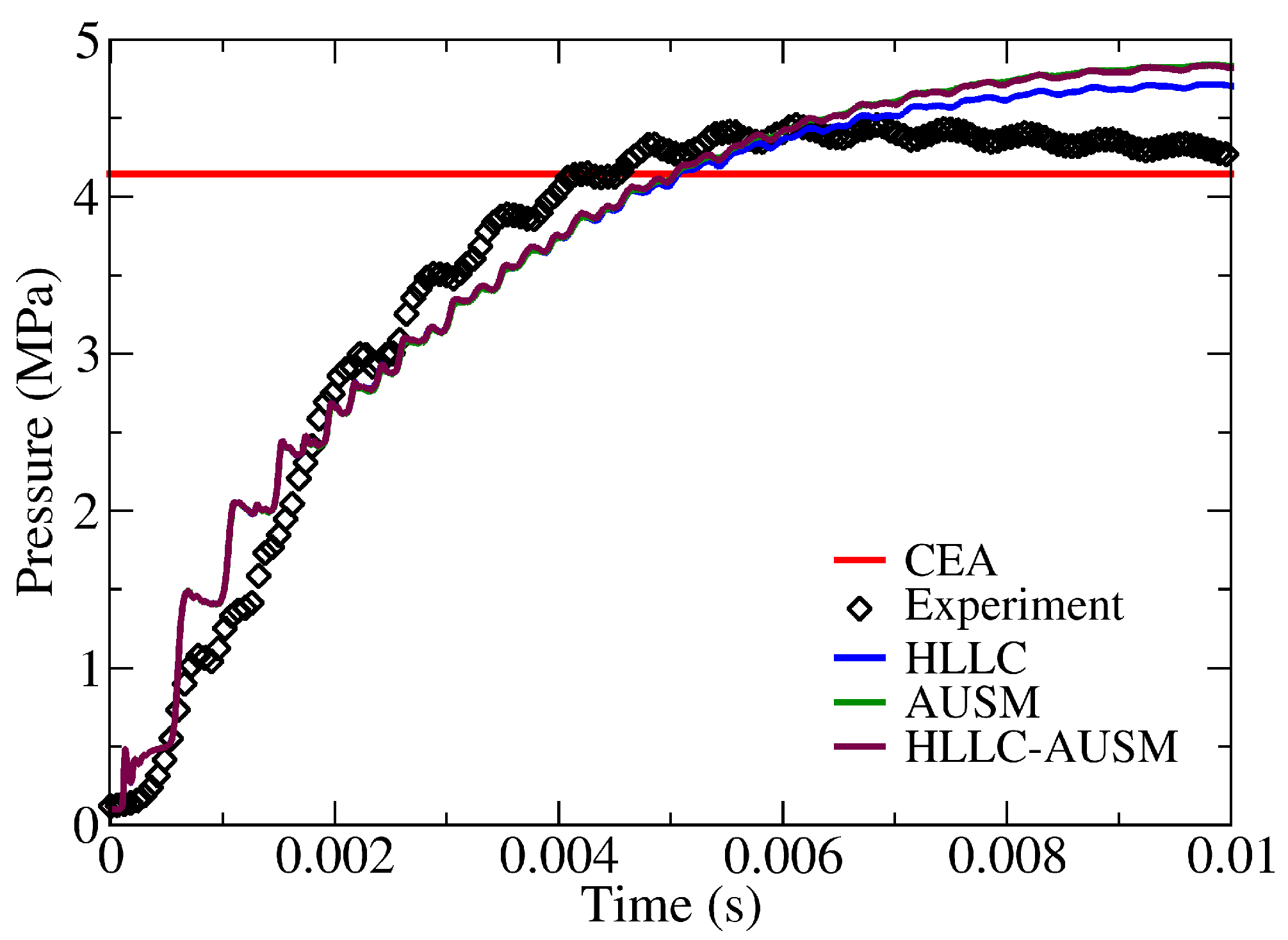
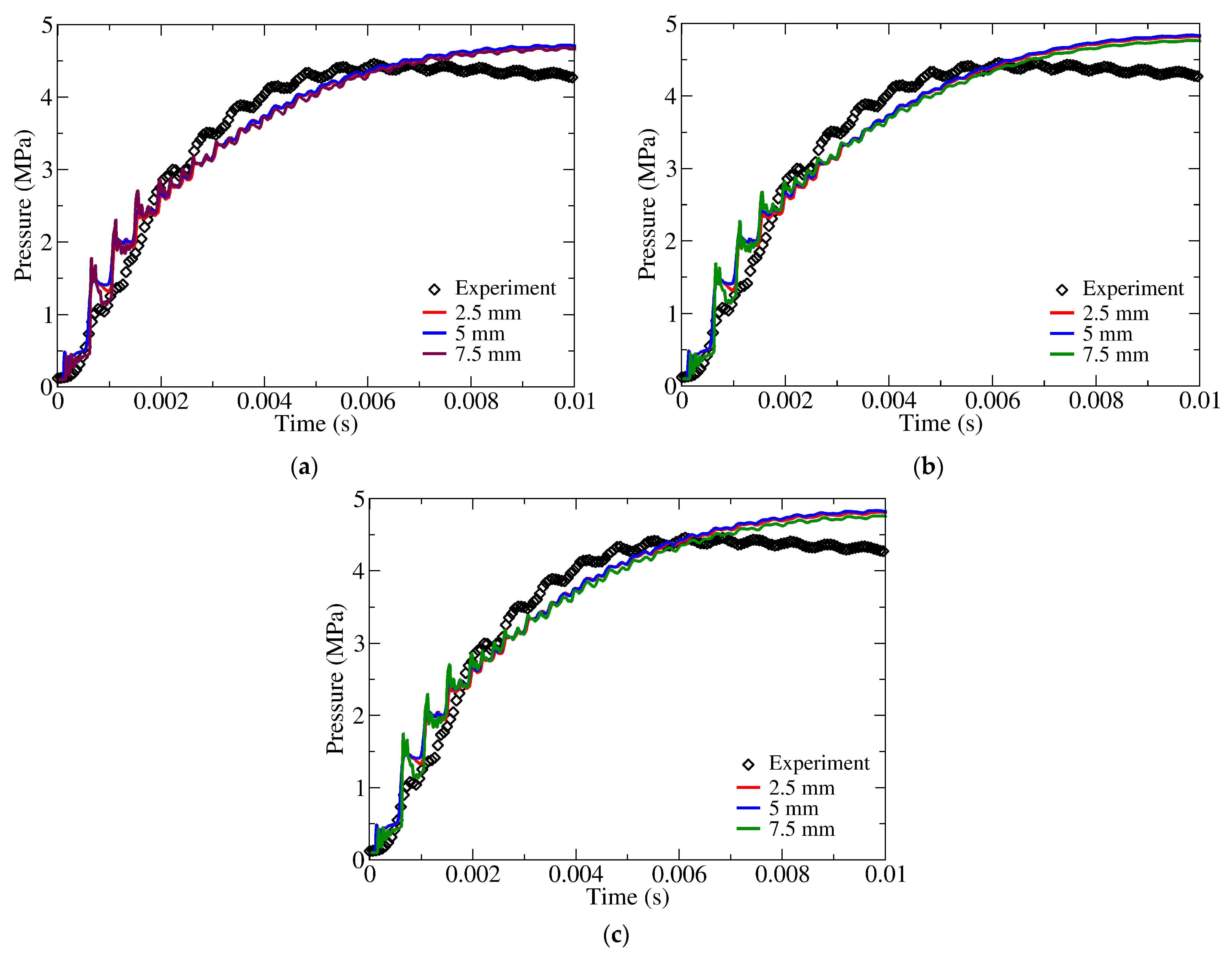
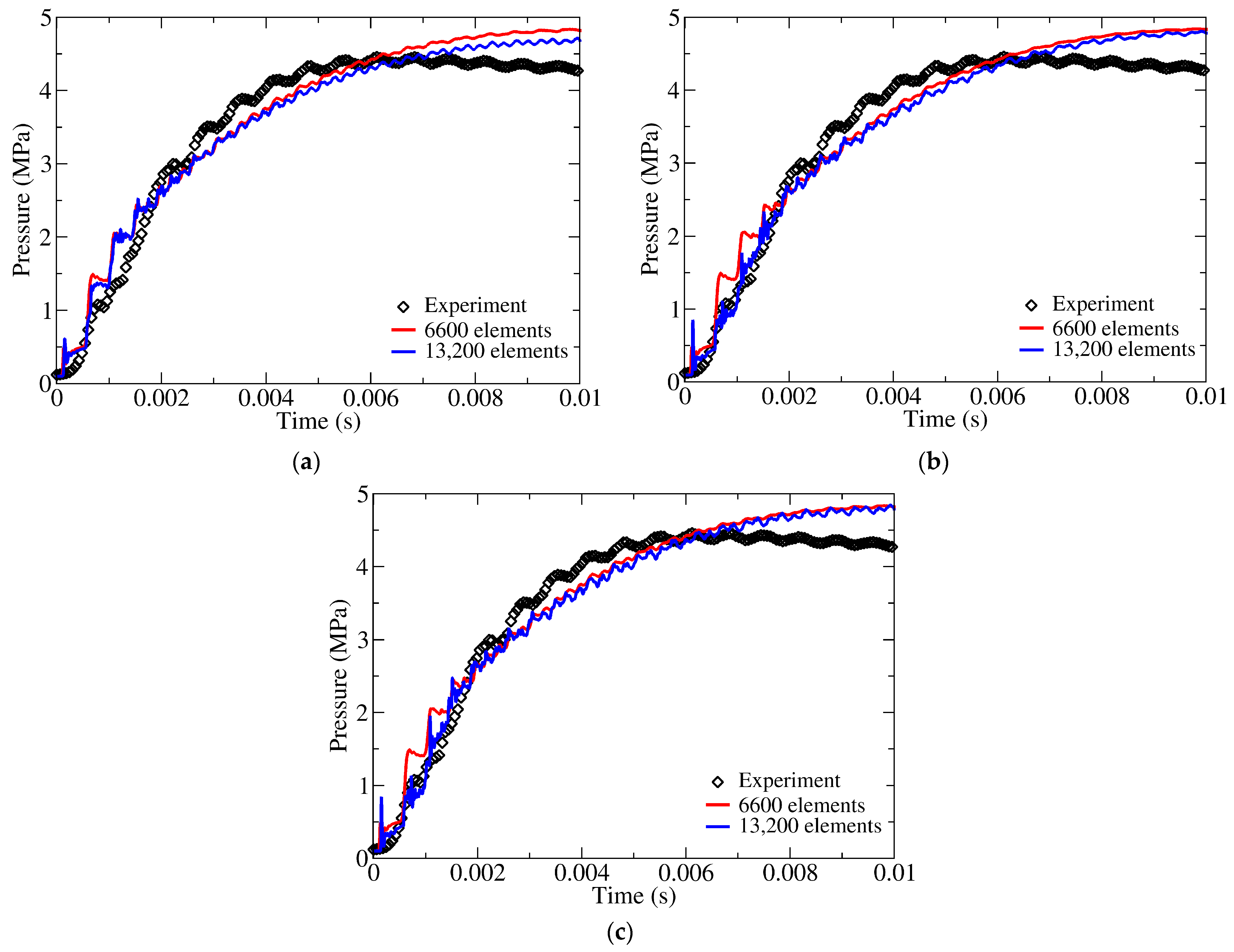
The closed bomb test is numerically simulated for the granular combustion of BPN with all three schemes and compared with the experimental results, as shown in Figure 6. The numerical prediction carried out by all of the schemes complements the experimental result. The simulation is terminated when the radius of the granules reaches the cutoff value, and the pressure remains constant after that, as heat loss to the surrounding area is not considered. A sensitivity study on the assumed initial ignited length is carried out. Simulations when the initial ignited length is 2.5 mm, 5 mm, and 7.5 mm are carried out with all of the schemes. The results are shown in Figure 7. It is observed that, irrespective of the initial ignition length assumption, the code predicts the pressure history well. Two sets of grids are taken, one with six thousand six hundred elements and another with thirteen thousand two hundred elements, for grid sensitivity studies with all three schemes, as shown in Figure 8. From this, the rest of the studies assume that 5 mm of the granular bed is ignited, and flux calculations are carried out using the HLLC scheme.
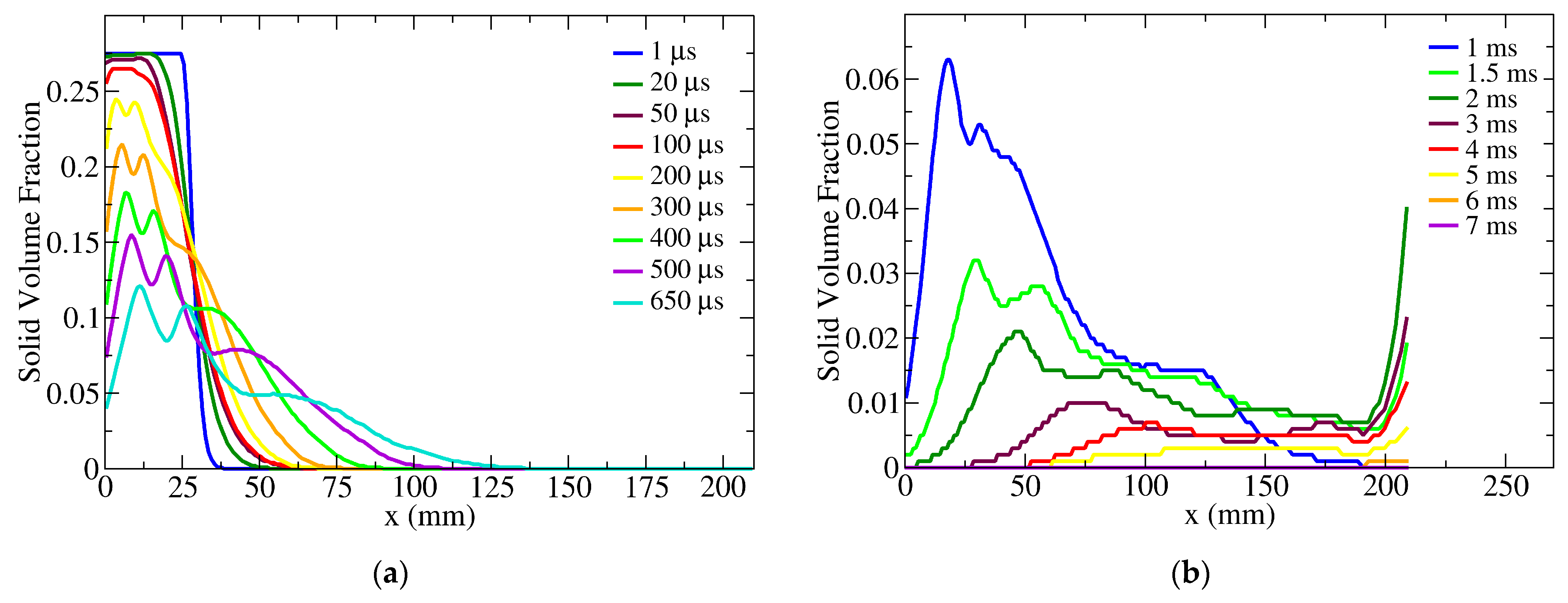
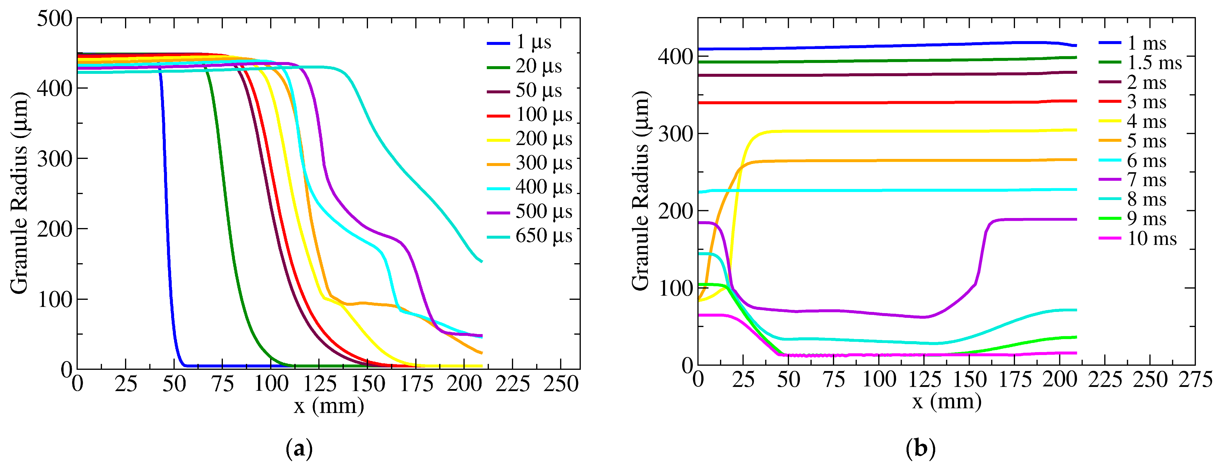
From the beginning to the complete combustion of the granules, the centerline plot for the evolution of solid volume fraction and the reduction in the granular radius are shown in Figure 9 and Figure 10, respectively. From Figure 9a and Figure 10a, the spreading of the granules to the entire domain from the initial 29 mm bed can be observed. The clear reduction in the solid volume fraction in the initial granular bed can be seen in Figure 9a. By 650 µs, the pressure in the chamber has risen from 1 bar to 5 bar, and from Figure 10a, it is visible that the radius of the granules has not reduced much, only from 448.5 µm to 423.4 µm. A significant reduction in the radius occurs after 650 µs until complete combustion at 10 ms as the pressure in the chamber rises from 5 bar to 47 bar. This is evident from Figure 10b, and at 10 ms, the radius of the granules has reached the cutoff radius, which is 5 µm throughout the domain.

7. Conclusions

This study focuses on experimentally recreating granular combustion through a closed bomb test, mathematically modeling the complete physics of granular combustion, numerically predicting the same, and comparing three numerical schemes. Boron potassium nitrate is used for this study, as it is widely used in various applications. A customized version of the seven-equation compressible multifluid formulation is curated and presented in this paper and is used for modeling. The finite volume method is used for spatial discretization, and three upwind schemes from the literature, namely HLLC, AUSM+-up, and a combination of the two families of schemes, referred to as HLLC-AUSM, are used for the comparative study. With these, an axisymmetric code is developed to predict and compare granular combustion. The developed code could predict granular combustion, and it complements the experimental result. The overall computation time for the HLLC scheme is slightly longer compared to the AUSM+-up and HLLC-AUSM schemes; however, there is not much to distinguish between them. All three schemes can predict granular combustion accurately. In future work, the chemical kinetics of granular BPN can be incorporated into the model for enhanced numerical predictions.

Author Contributions

Conceptualization, A.R.E., T.J. and P.A.R.; methodology, A.R.E. and T.J.; solver, A.R.E. and T.J.; computational analysis, A.R.E. and T.J.; experimental investigation, S.S., P.A.R. and M.B.; resources, P.A.R. and M.B.; experimental data curation, S.S. and P.A.R.; computational data curation, A.R.E. and T.J.; writing—original draft preparation, A.R.E.; writing—review and editing, A.R.E., S.S., T.J., P.A.R. and M.B.; visualization, A.R.E.; supervision, T.J. and P.A.R.; approval, M.B.; project administration, T.J., P.A.R. and M.B.; funding acquisition, T.J., P.A.R. and M.B. All authors have read and agreed to the published version of the manuscript.

Funding

This research received funding from the DRDO Industry Academia Centre of Excellence, IIT Madras (DIA-CoE, IITM).

Data Availability Statement

The datasets presented in this article are not readily available because the data are part of an ongoing study.

Acknowledgments

The authors express their gratitude to Tirthadeb Gosh, an MS scholar in the Department of Aerospace Engineering, IIT Madras, for carrying out the burn rate experiments for granular BPN.

Conflicts of Interest

The authors declare no conflicts of interest. The funders had no role in the design of the study; in the collection, analyses, or interpretation of data; or in the writing of the manuscript.

Nomenclature

M ˙ mass generated
aspeed of sound
Ddrag
Etotal energy
Etotal flux vector
e internal energy
Faxial flux vector
Gradial flux vector
Hcheat of combustion
Nnumber density per unit volume
Ppressure
Qheat transfer
qvelocity vector
rradial direction
Ssource term vector
Swave speed
ttime
Ttemperature
Uconserved variables vector
uaxial velocity
v radial velocity
x axial direction
Ylocal mass fraction
Greek
volume fraction
µpressure relaxation
γspecific heat ratio
ξgaseous combustion products mass fraction
τpressure relaxation time
Ωvolume
ρ density
Subscripts
ggas phase
Iinterface
icomputational cell
kgas/solid phase
l/L left
p solid phase
qcondensed phase combustion products
r/Rright
Abbreviations
AUSMadvection upstream splitting method
BPNboron potassium nitrate
CEAchemical equilibrium compositions and applications
HLLCHarten-Lax-van Leer-Contact

References

  1. Kuo, K.K. Principles of Combustion, 1st ed.; Wiley-Interscience: Hoboken, NJ, USA, 1986; pp. 601–614. [Google Scholar]
  2. Krier, H.; Gokhale, S. Predictions of vigorous ignition dynamics for a packed bed of solid propellant grains. Int. J. Heat Mass Transf. 1976, 8, 915–923. [Google Scholar] [CrossRef]
  3. Kuo, K.K.; Vichnevetsky, R.; Summerfield, M. Theory of flame front propagation in porous propellant charges under confinement. AIAA J. 1973, 11, 444–451. [Google Scholar] [CrossRef]
  4. Powers, J.; Stewart, D.; Krier, H. Theory of two-phase detonation—Part i: Modeling. Combust. Flame 1990, 80, 264–279. [Google Scholar] [CrossRef]
  5. Powers, J.M.; Gonthier, K.A. Pyrotechnic modelling for the NSI driven pin puller. Intern. Fluid Mech. Div. 1992. [Google Scholar]
  6. Gonthier, K.A.; Powers, J.M. Formulations, predictions, and sensitivity analysis of a pyrotechnically actuated pin puller model. J. Propuls. Power 1994, 10, 501–507. [Google Scholar] [CrossRef]
  7. Bdzil, J.; Menikoff, R.; Son, S.; Kapila, A.; Stewart, D.S. Two-phase modeling of deflagration-to-detonation transition in granular materials: A critical examination 46 of modeling issues. Phys. Fluids 1999, 11, 378–402. [Google Scholar] [CrossRef]
  8. Saurel, R.; Le Martelot, S.; Tosello, R.; Lapebie, E. Symmetric model of compressible granular mixtures with permeable interfaces. Phys. Fluids 2014, 26, 123304. [Google Scholar] [CrossRef]
  9. Saurel, R.; Chinnayya, A.; Carmouze, Q. Modelling compressible dense and dilute two-phase flows. Phys. Fluids 2017, 29, 063301. [Google Scholar] [CrossRef]
  10. Davis, T.; Kuo, K. Experimental study of the combustion processes in granular propellant beds. J. Spacecr. Rocket. 1979, 16, 203–209. [Google Scholar] [CrossRef]
  11. Han, D.-H.; Sung, H.-G.; Ryu, B.-T. Numerical simulation for the combustion of a zirconium/potassium perchlorate explosive inside a closed vessel. Propellants Explos. Pyrotech. 2017, 42, 1168–1178. [Google Scholar] [CrossRef]
  12. Ulas, A.; Risha, G.A.; Kuo, K.K. An investigation of the performance of a boron/potassium-nitrate based pyrotechnic igniter. Propellants Explos. Pyrotech. Int. J. Deal. Sci. Technol. Asp. Energ. Mater. 2006, 79, 311–317. [Google Scholar] [CrossRef]
  13. Yeom, G.S.; Chang, K.S. A modified HLLC-type Riemann solver for the compressible six-equation two-fluid model. Comput. Fluids 2013, 76, 86–104. [Google Scholar] [CrossRef]
  14. Furfaro, D.; Saurel, R. A simple HLLC-type Riemann solver for compressible non-equilibrium two-phase flows. Comput. Fluids 2015, 111, 159–178. [Google Scholar] [CrossRef]
  15. Kitamura, K.; Liou, M.S.; Chang, C.H. Extension and comparative study of AUSM-family schemes for compressible multiphase flow simulations. Commun. Comput. Phys. 2014, 16, 632–674. [Google Scholar] [CrossRef]
  16. Houim, R.W.; Oran, E.S. A technique for computing dense granular compressible flows with shock waves. arXiv 2013, arXiv:1312.1290. [Google Scholar]
  17. Houim, R.W.; Oran, E.S. A multiphase model for compressible granular–gaseous flows: Formulation and initial tests. J. Fluid Mech. 2016, 789, 166–220. [Google Scholar] [CrossRef]
  18. Gordon, S.; McBride, B.J. Computer Program for Calculation of Complex Chemical Equilibrium Compositions and Applications; NASA Reference Publication 1311; NASA Lewis Research Center: Cleveland, OH, USA, 1994. [Google Scholar]
  19. Yeom, G.S.; Chang, K.S. Dissipation of shock wave in a gas-droplet mixture by droplet fragmentation. Int. J. Heat Mass Transf. 2012, 55, 941–957. [Google Scholar] [CrossRef]
  20. Isherwood, L.; Grant, Z.J.; Gottlieb, S. Strong stability preserving integrating factor Runge–Kutta methods. SIAM J. Numer. Anal. 2018, 56, 3276–3307. [Google Scholar] [CrossRef]
  21. Blazek, J. Computational Fluid Dynamics: Principles and Applications, 1st ed.; Elsevier: Amsterdam, The Netherlands, 2001; pp. 129–133. [Google Scholar]
  22. Michalak, K.; Ollivier-Gooch, C. Differentiability of slope limiters on unstructured grids. In Proceedings of the Fourteenth Annual Conference of the Computational Fluid Dynamics Society of Canada, Kingston, Canada, 16–18 July 2006. [Google Scholar]
  23. Batten, P.; Clarke, N.; Lambert, C.; Causon, D.M. On the choice of wavespeeds for the HLLC Riemann solver. SIAM J. Sci. Comput. 1997, 18, 1553–1570. [Google Scholar] [CrossRef]
  24. Liou, M.S. A sequel to AUSM, Part II: AUSM+-up for all speeds. J. Comput. Phys. 2006, 214, 137–170. [Google Scholar] [CrossRef]
  25. Kim, B.; Jang, S.-G.; Yoh, J.J. A full-scale hydrodynamic simulation of energetic component system. Comput. Fluids 2017, 156, 368–383. [Google Scholar] [CrossRef]
  26. Wang, L.; Feng, C.; Han, C. Experimental study on boron-potassium nitrate initiated by shock. J. Propuls. Power 1998, 14, 416–420. [Google Scholar] [CrossRef]
  27. Ding, D. A study on the ignition of boron/potassium nitrate mixture. Sci. Technol. Energ. Mater. 2006, 67, 23. [Google Scholar]
  28. Wu, J.; Liu, J.; Yang, L.; Li, Y.; Chen, L. Numerical simulation of the metal bridge foil explosion plasma ignition of B/KNO3. Phys. Plasmas 2020, 27, 033509. [Google Scholar] [CrossRef]
Figure 1. Closed bomb test setup.
Aerospace 11 00251 g001
Figure 2. Drawing of closed bomb.
Aerospace 11 00251 g002
Figure 3. Granular BPN.
Aerospace 11 00251 g003
Figure 4. Experimental pressure history and CEA predicted peak pressure.
Aerospace 11 00251 g004
Figure 5. Computational domain.
Aerospace 11 00251 g005
Figure 6. Pressure history numerical and experimental comparison.
Aerospace 11 00251 g006
Figure 7. Sensitivity studies on initial ignition length: (a) HLLC, (b) AUSM, and (c) HLLC-AUSM.
Aerospace 11 00251 g007
Figure 8. Grid sensitivity: (a) HLLC, (b) AUSM, and (c) HLLC-AUSM.
Aerospace 11 00251 g008
Figure 9. Solid volume fraction evolution during granular combustion (a) 1 μs to 650 μs (b) 1 ms to 7 ms.
Aerospace 11 00251 g009
Figure 10. Reduction in granular radius during granular combustion (a) 1 μs to 650 μs (b) 1 ms to 10 ms.
Aerospace 11 00251 g010
Table 1. Pressure sensor specifications.
ParametersValue
Make and model numberKulite; EWCTV 312(M)
Pressure range140 bar
Operating temperature range297 to 1366 K
Residual unbalance0.5 V ± 100 mV
Uncertainty in pressure measurement ± 0.1% of full scale (FS)
Table 2. Input parameters for simulation.
ParametersValueSource
Density (kg/m3)2000measured
Diameter (µm)897measured
Volume of one granule0.3779calculated
Surface area–volume relation4.836Vol0.67sphere correlation
Burn rate law (mm/s; P in bar)19.75P0.19measured
Speed of sound (m/s)2463Kim et al. [25]
BPN specific heat ratio2.2023computed from Wang et al. [26]
P α (GPa)6.075computed from Wang et al. [26]
Initial solid volume fraction0.275calculated
Length occupied in the canister (mm)29measured
Initial pressure (bar)1ambient condition
Initial temperature (K)308.15ambient condition
Ignition temperature (K)834Dayu [27]
Flame temperature (K)3011.5CEA analysis [18]
Heat of combustion (kJ/kg)7773.2Wu et al. [28]
Disclaimer/Publisher’s Note: The statements, opinions and data contained in all publications are solely those of the individual author(s) and contributor(s) and not of MDPI and/or the editor(s). MDPI and/or the editor(s) disclaim responsibility for any injury to people or property resulting from any ideas, methods, instructions or products referred to in the content.