Article

Recycling Space Beverage Packaging into LDPE-Based Composite Materials

Department of Astronautical, Electrical and Energy Engineering, Sapienza University of Rome, Via Salaria 851-881, 00138 Rome, Italy
*
Author to whom correspondence should be addressed.
Aerospace 2024, 11(12), 957; https://doi.org/10.3390/aerospace11120957
Submission received: 30 September 2024 / Revised: 12 November 2024 / Accepted: 18 November 2024 / Published: 21 November 2024

Abstract

:
Long-term space missions require careful resource management and recycling strategies to overcome the limitations of resupply missions. In this study, we investigated the potential to recycle space beverage packaging, which is typically made of low-density polyethylene (LDPE) and PET-aluminum-LDPE (PAL) trilaminate, by developing a LDPE-based composite material with PAL inclusions. Due to the limited availability of space beverage packaging, we replaced it with LDPE powder and commercial coffee packaging for the experiments. Fourier transform infrared spectroscopy (FTIR) was employed to thoroughly analyze the composition of the commercial coffee packaging. The simulant packaging was reduced to a filler, and its thermal properties were characterized by differential scanning calorimetry (DSC), while the particle size was analyzed via scanning electron microscopy (SEM) and the bootstrap resampling technique. Composite specimens were then fabricated by incorporating the filler into the LDPE matrix at loadings of 5 wt% and 10 wt%, and their mechanical and thermal properties were assessed through dynamic mechanical analysis (DMA) and thermal conductivity measurements. The 10 wt% corresponds approximately to the radio between PAL and PE in space beverage packaging and is, therefore, the maximum usable percentage when considering a single package. The results indicate that, as the filler loading increased, the mechanical performance of the composite material decreased, while the thermal conductivity was significantly improved. Finally, 10 wt% LDPE/PAL filaments, with a diameter of 1.7 mm and suitable for the fused filament technique, were produced.

1. Introduction

In recent years, interest in long-term space colonization has been fueled by several factors.
Technological advancements, such as those seen in ambitious projects like the Artemis program, have expanded the possibilities for human presence beyond Earth [1,2,3]. Additionally, efforts to explore Mars and establish a permanent human settlement there have sparked significant public interest, fueling discussions and inspiring new projects in this area [4,5,6]. Private companies, such as Elon Musk’s SpaceX [7] and Jeff Bezos’s Blue Origin [8], have also invested substantial resources to developing advanced space technologies with the aim of creating human colonies on other planets [9,10,11]. Furthermore, growing environmental challenges on Earth and concerns over resource depletion have spurred the quest of alternative solutions, with space colonization increasingly viewed as a potential long-term response [12,13].
The viability of long-term space missions and future colonization efforts depends on sustainable resource management. Jones analyzed the costs of resupply missions and found that in situ resource utilization and recycling are crucial for long-term missions [14]. The growing amount of waste generated in space underscores the need for innovative solutions beyond traditional storage and incineration methods [15,16]. Trash-to-gas technology presents a promising solution for waste management. Olson et al. have demonstrated that this process consistently reduces waste mass across various trash-to-gas systems [17]. Voyager Space, partnering with NASA, has developed a new waste management system for the International Space Station (ISS). This system involves a specialized container that stores waste until it is full, after which the container is released from the ISS and incinerated upon reentry into Earth’s atmosphere [18]. Recently, a novel sustainable approach, based on recycling, has gained traction. Additive manufacturing (AM) has become a leading technology for sustainable waste management in long-duration space missions, offering advantages such as rapid prototyping and the ability to create highly customized items [19,20]. While AM has advanced significantly in recent years [21], adapting it for space presents unique challenges. Unlike terrestrial manufacturing, which occurs under Earth’s gravity (1 g), in-space manufacturing (ISM) operates in reduced-gravity environments. This includes microgravity (µg) during spaceflight and partial gravity on planetary bodies [22]. Fused filament fabrication (FFF) is the most extensively tested additive manufacturing technique in space. In this process, a filament is fed through a heated chamber, where it melts and is extruded through a nozzle onto a substrate. The material then solidifies, forming layers that build upon each other to create the desired object [23]. FFF has been successfully demonstrated in reduced-gravity environments, making it a promising technology for future space-based manufacturing applications [22]. A groundbreaking achievement in 2014, the successful integration of the first FFF 3D printer onto the ISS, a joint effort between NASA and Made In Space (MIS), validated the feasibility of AM in microgravity. To evaluate the effects of microgravity on FFF, identical acrylonitrile butadiene styrene (ABS) samples were fabricated both in space and on Earth using the same type of printer. Prater et al. demonstrated that microgravity has no significant engineering impact on the FFF process [24]. The Additive Manufacturing Facility (AMF), the second FFF 3D printer on the ISS, has been operational since 2016. Capable of printing with ABS, ULTEM 9085, and high-density polyethylene (HDPE), the AMF represents a significant advancement in ISM capabilities [25]. Tethers Unlimited, Inc. (TUI) developed the ReFabricator, a revolutionary device that combines recycling and 3D printing. It can recycle any shape of polymer waste, processing it into high-quality filament for use in its integrated 3D printer [26]. In the last two years, NASA has partnered with Redwire Corporation to develop FabLab, a cutting-edge Multimaterial Fabrication Laboratory. Originally intended for the ISS, FabLab is envisioned as a crucial asset for future lunar and Martian missions. FabLab’s in situ manufacturing capabilities aim to enhance mission flexibility and support the long-term sustainability of human space exploration by reducing reliance on ground-supplied resources [27]. Aligned with current research efforts to advance the recycling of waste materials for producing new components through in situ AM techniques, this study aims to assess the feasibility of creating a filament for the future FFF 3D printing of a composite material, where both the matrix and filler are derived from recycled food packaging. Specifically, this investigation focuses on beverage packaging, where the septum adapter and straw are made of low-density polyethylene (LDPE), and the entire beverage packaging is made of PET-aluminum-LDPE (PAL) trilaminate. In this study, the septum adapter and straw constitute the matrix, while the complete food packaging serves as the reinforcement in a newly developed composite material made entirely from recycled components. It is important to highlight that this novel composite material, which contains a high percentage of hydrogen-rich LDPE, shows promise as a material for attenuating space radiation, particularly neutron radiation, due to hydrogen’s ability to reduce neutron energy [28]. Moreover, the incorporation of the PAL filler, which includes an additional percentage of LDPE and aluminum, enhances the composite’s density and its effectiveness in attenuating gamma radiation [29]. These attributes make LDPE-PAL composite a potential highly effective solution for 3D-printed radiation shielding applications. Given the limited availability of space beverage packaging, surrogate materials have been used to simulate the various components of the beverage packaging itself.

2. Materials and Methods

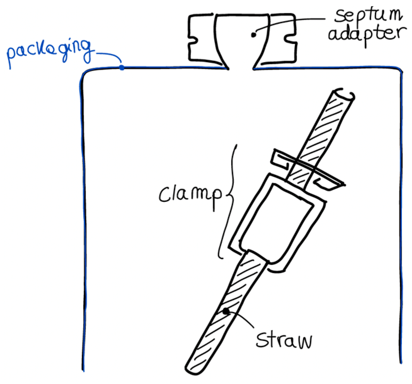
2.1. Sample Preparation

Coffee packaging was selected as surrogate material to simulate the composition of space beverage packaging. Both types of packaging commonly employ trilaminate film consisting of polyethylene terephthalate (PET), aluminum, and LDPE [30,31]. To create the PET-aluminum-LDPE (PAL) filler for incorporation into the LDPE matrix, the trilaminate coffee packaging material was grated and then sieved using a 60-mesh screen (Sigma Aldrich, Darmstadt, Germany).
In detail, the trilaminate material from the surrogate coffee packaging was processed into filler using a hand-cranked mechanism that was designed and 3D-printed entirely in-house to expedite the shredding process. The geometry and kinematics of the mechanism were modeled and assembled using CATIA V5 (Dassault Systèmes, Vélizy-Villacoublay, France) (Figure 1a). The CAD design for each component was exported in digital format and processed using Ultimaker Cura software, version 5.8.1., where printing parameters were assigned. The various parts of the mechanism were fabricated in nylon using the Ultimaker 3D printer (Figure 1b). After printing, the mechanism was assembled and equipped with a commercial grater to produce the PAL filler.
LDPE matrix was purchased from Thermo Fisher Scientific in the form of powder with a particle size of approximately 500 µm. The PAL filler was added to the PE matrix by mechanical mixing. The specimens were fabricated at loadings of 5 wt% and 10 wt% of PAL relative to the polymer mass. The filler loadings of 5 wt% and 10 wt% were chosen after a detailed evaluation of the packaging components (Figure 2) and their respective masses, aimed at achieving more effective recycling. Based on the datasheet for stand-up pouches [32], which is similar to those used for coffee packaging, the thicknesses of the three trilaminate layers were identified as 12 µm for PET, 6 µm for aluminum, and 75 µm for LDPE. Referring to the maximum dimensions of space beverage packaging (22.35 × 9.14 cm, as noted in Ref. [33]), the total packaging mass was calculated to be 2 g. For the LDPE components [34], which included the septum adapter and straw, the septum adapter weighed 9 g, while the straw, equipped with a clamp to seal the packaging contents, had a mass of 10 g, resulting in a total combined mass of approximately 20 g. Based on this information, a filler loading of 5 wt% was used to achieve a 50% recycling rate for the trilaminated PAL, while a 10 wt% filler was implemented to enable complete recycling of the packaging along with its associated components.
The fabrication steps for the LDPE/PAL composite specimen are shown in Figure 3. Following the previously described shredding, sieving, and mixing steps, samples were prepared using a casting process under vacuum. The temperature and holding time were adjusted iteratively, beginning at the standard melting temperature of LDPE (Tm = 110 °C). This approach was taken to minimize shrinkage and prevent bubble formation. The optimal casting parameters were determined as 130 °C for 2 h in an oven under vacuum.

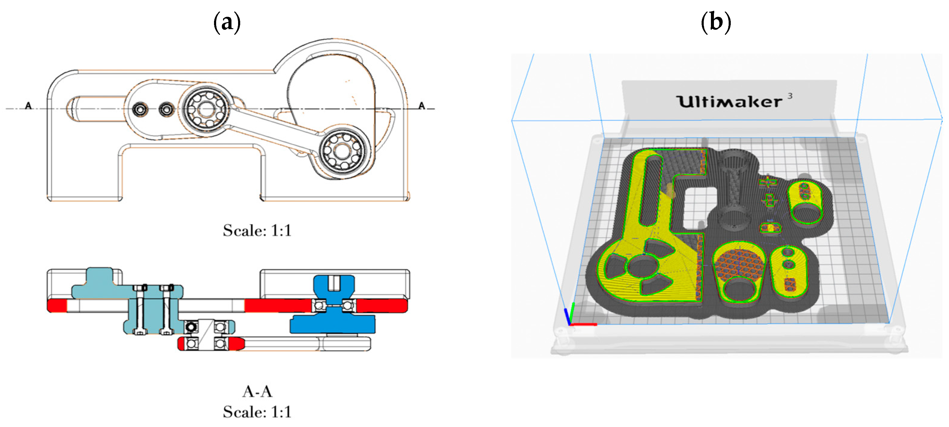
2.2. Extrusion Process for Filament Fabrication

Extruded filaments were fabricated from LDPE-PAL 10 wt% pellets using a Felfil Evo extruder (Felfil, Turin, Italy) with a 1.75-mm diameter nozzle. The pellets were produced using the process described above. The optimal extrusion parameters were determined through an iterative process to achieve a consistent circular cross-section of extruded filament, ensuring high-quality 3D printing [35,36]. At the end of the iterative process, a chamber temperature of 135 °C and a screw speed of 6 rpm were selected as the optimized parameters, and LDPE-based filaments with a 10 wt% of PAL loading were successfully produced.

2.3. Characterization Methods

To confirm the chemical composition of the coffee packaging materials and thereby assess their similarity to space beverage packaging, a preliminary qualitative Fourier transform infrared spectroscopy (FTIR) analysis was performed. This analysis was conducted using a Nicolet Summit Spectrometer (Thermo Fisher Scientific, Waltham, MA, USA) with a zinc selenide attenuated total reflectance (ATR) crystal. The resulting spectra were shown in terms of transmittance.
Since the size and distribution of trilaminate filler particles were unknown a priori, the diverse shapes of filler particles required a detailed examination. The particle distribution of trilaminate filler was estimated by processing SEM images using Image-J software [37]. The images were filtered and binarized to highlight the boundaries of each particle. SEM images of the PAL trilaminate were acquired using a VEGA LSH SEM (Tescan, Brno, Czech Republic). To characterize the distribution of particles with a broad range of shapes, the Feret diameter was chosen as a representative parameter for the particle size (Figure 4). The Feret diameter is a statistical measurement extensively used to characterize the size of micrometric particles with irregular shapes, and it is defined as the perpendicular distance between parallel tangents on opposite sides of the profile [38].
The particle distribution determined by the SEM image analysis exhibited a non-normal pattern, characterized by high standard deviations. This deviation from normality posed challenges for accurately estimating the average particle size using traditional statistical methods. To address this issue, a bootstrap resampling technique was employed, allowing for a more reliable estimation of the average particle size despite the non-normal distribution. Bootstrapping is a statistical method that involves repeatedly sampling with replacements from an original dataset. By creating multiple resampled datasets, bootstrapping provides a distribution of the statistic of interest, allowing for a more robust estimation of its variability and uncertainty. In this case, bootstrapping was applied 250 times with replacements, generating 250 resampled datasets to improve the accuracy and reliability of the particle size estimation [39]. By resampling the original dataset numerous times and calculating the average particle size for each resampled dataset, the distribution of the average particle sizes was obtained. Analyzing the particle sizes and distribution provided insights into how the filler particles might interact with the polymer matrix and influence the composite’s properties. This information is essential for optimizing the filler loading and improving the overall performance of the composite material.
Figure 4. Particle Feret diameter [40].
Aerospace 11 00957 g004
Differential scanning calorimetry (DSC) was performed on trilaminate filler samples using a Pyris 8500 instrument (PerkinElmer, Waltham, MA, USA). Five powder samples, each weighing approximately 5 mg, were sealed in aluminum pans with lids and analyzed over a temperature range from 20 °C to 150 °C. A five-step heating and cooling cycle was employed, as shown in Figure 5. The first heating cycle was conducted from 20 °C to 150 °C to gather information about the thermal history of the material. The second step was isothermal holding at 150 °C for 2 min, which served to stabilize the thermodynamic state of the material. Then, a cooling cycle from 150 °C to 20 °C was performed to gather data on the crystallization behavior of the powder sample. Another isothermal holding at 20 °C for 2 min followed to further stabilize the material. Finally, a second heating cycle from 20 °C to 150 °C was performed to obtain information regarding the melting behavior of the sample. The mentioned heating and cooling cycles were performed at a heating and cooling rate of 10 °C/min under a nitrogen flow of 20 cc/min.
From the heating and cooling cycle curves, the onset, starting, ending, and peak temperatures for the melting and crystallization transitions were obtained, along with the specific enthalpy values. From the specific enthalpy for the melting transition, ΔHf, the degree of crystallinity, χ, was calculated using the following equation:
χ = Δ H f Δ H 0 f
where ΔH0f is the specific enthalpy reference value. In this work, ΔH0f = 293 J/g was taken as a reference, according to [41].
DMA tests were conducted with a Mettler Toledo DMA-1 (Mettler Toledo, Columbus, OH, USA) using a single-cantilever operational mode configuration, as shown in Figure 6, to measure the elastic modulus as a function of the temperature.
A displacement sweep was performed at a constant temperature of 30 °C, with the displacement amplitude varying from 1 µm to 200 µm at frequency of 1 Hz. This test was conducted to determine the appropriate displacement amplitude to apply during the test, ensuring that the material deformed within its linear viscoelastic region. Figure 7 shows the normalized storage modulus as a function of the displacement amplitude, obtained from the displacement sweep test on a pristine LDPE sample. The linear viscoelastic behavior was observed to lie approximately between 1 µm and 75 µm. Therefore, the displacement amplitude for testing LDPE samples was set to 35 µm.
Subsequently, displacement sweeps were conducted for the samples with each filler weight fraction. The linear range observed was consistent with that of the pristine LDPE. As a result, all tests were performed in the displacement control mode using a displacement amplitude of 35 µm.
To characterize the mechanical behavior of the pristine LDPE and the LDPE with varying PAL loading percentages, dynamic temperature scans were conducted on three samples of each type of specimen. The temperature was programmed to rise from 30 °C to 130 °C at a rate of 5 °C/min, with a fixed displacement amplitude of 35 µm and a standard frequency of 1 Hz. The upper limit of the scanned temperature range was selected based on the maximum temperature reached on the lunar surface at the equator during the daytime in order to simulate extreme temperature conditions [42,43].
The thermal conductivity was measured using a Hot Disk TPS 1000 (Hot Disk, Gothenburg, Sweden) thermal analyzer under controlled conditions: room temperature (23 °C, as measured by a PT100 temperature sensor), 31.13 mW of heating power, and an 80 s measurement duration, using the Kapton 5465 F2 sensor (Hot Disk Sensors, Elk Grove, CA, USA). The samples analyzed included pure LDPE and LDPE composites containing 5 wt% and 10 wt% of trilaminate PAL filler. Accurate measurements of the thermal conductivity are crucial for various applications, including thermal management in electronics, building insulation, and heat exchange systems. Understanding the thermal conductivity of materials is essential for designing efficient and effective systems that can transfer or retain heat as needed.

3. Results

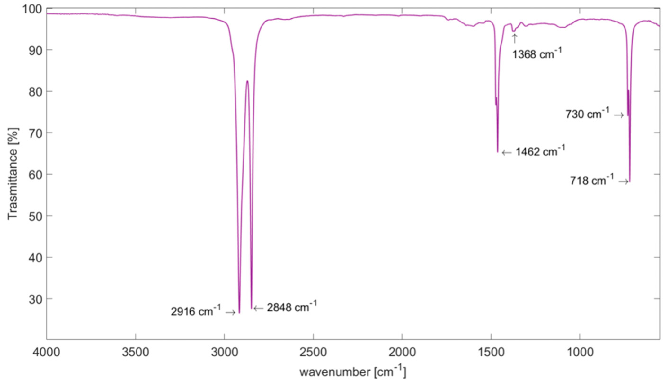
3.1. Fourier Transform Infrared Spectroscopy
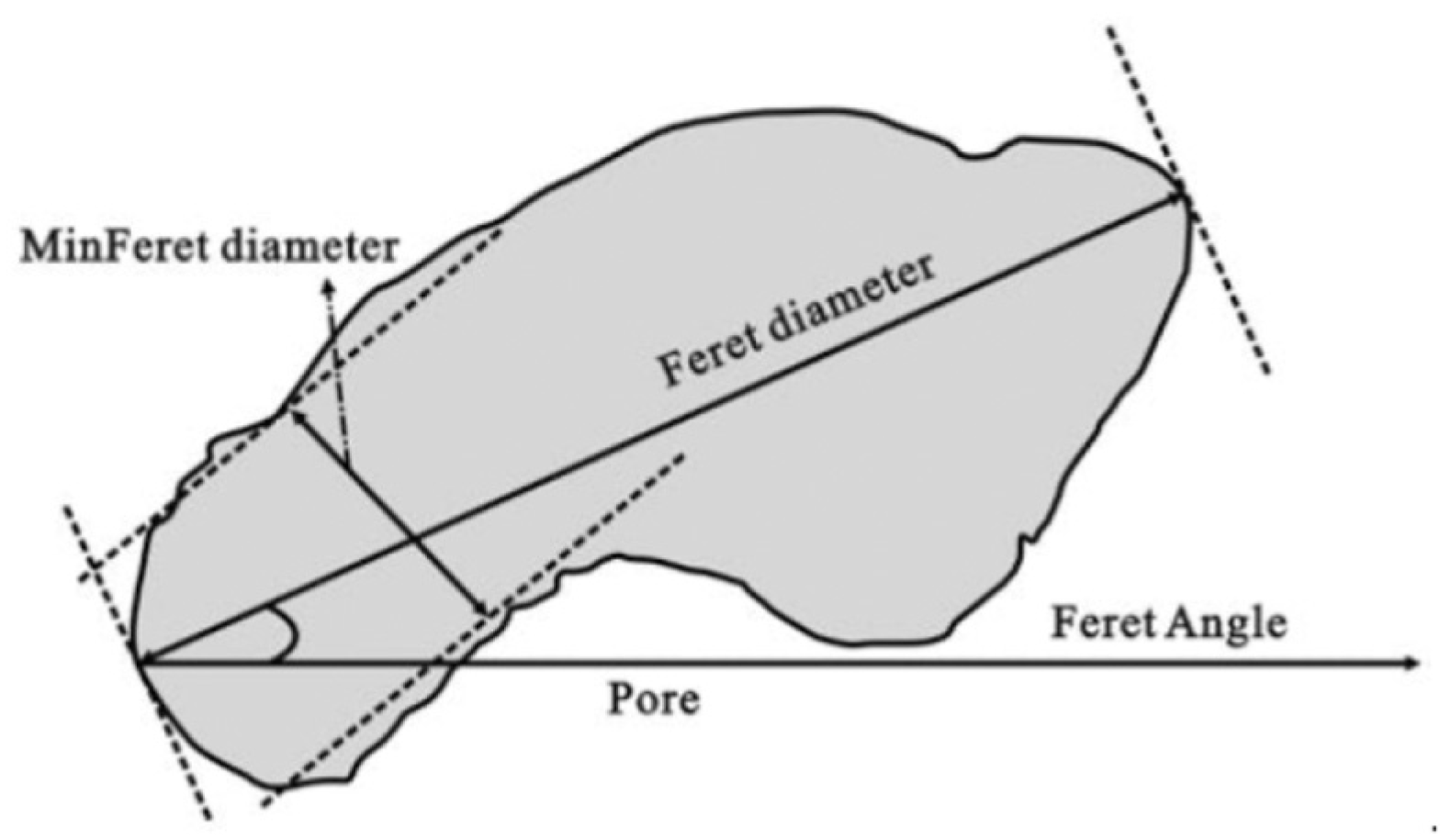
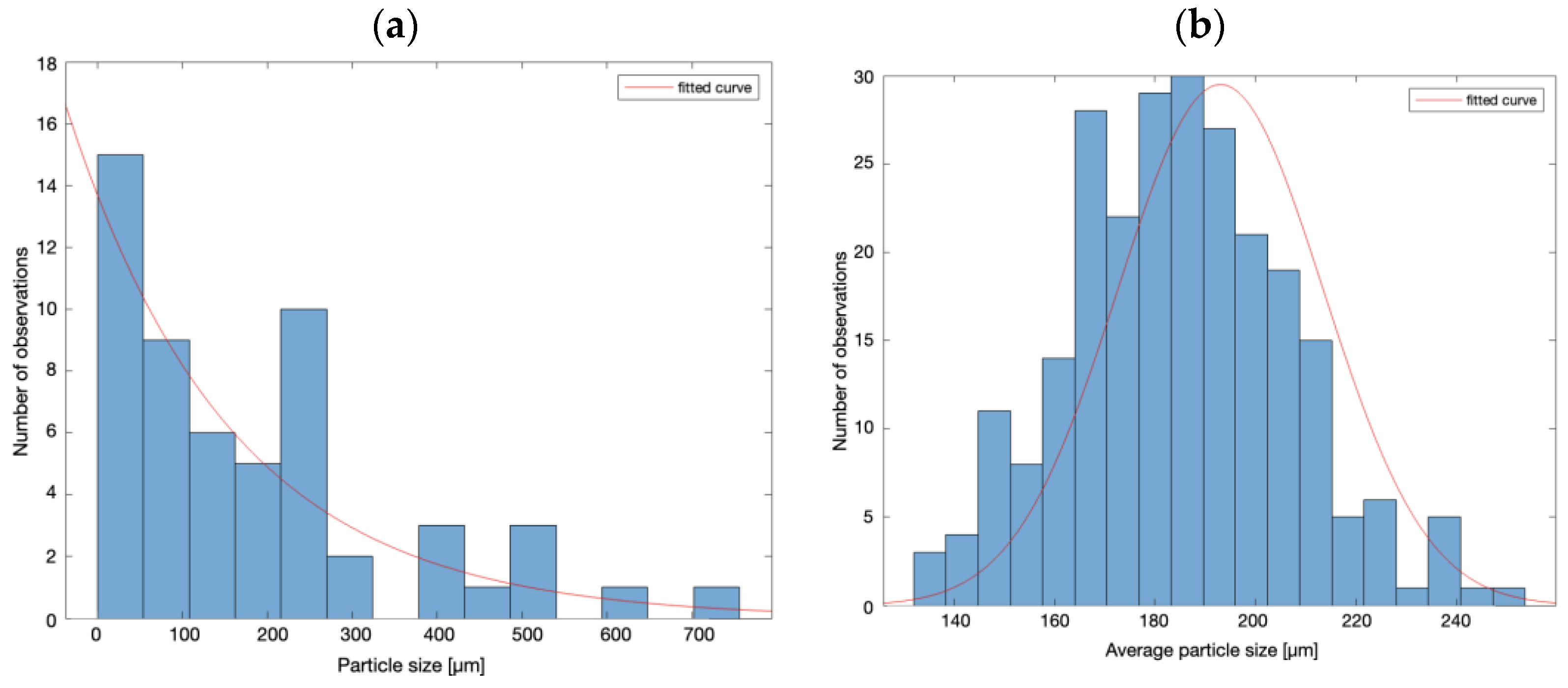
Space beverage packaging contains both LLDPE and LDPE [44]. In the case of coffee packaging, the recycling code labeled C/LDPE 90 indicates a composition predominantly made of LDPE, along with aluminum and PET. FTIR analysis was mainly performed to investigate the potential presence of LLDPE within these materials. Additionally, for completeness, an analysis was conducted on the reverse side of the packaging, focusing on the PET spectrum.
The qualitative analysis involved the determination of characteristic peaks associated with the molecular vibrations. The inner side spectrum (Figure 8) shows two C–H asymmetric and symmetric stretching vibrations identified by two narrow peaks at 2916 cm−1 and 2848 cm−1, respectively [45]. Bending [46] and wagging [47] vibrations of CH2 were observed in the bands of 1462 cm−1 and 1368 cm−1 respectively. Two C–H rocking modes peaks appeared in the fingerprint region at 730 cm−1 and 718 cm−1 [45], revealing a spectrum that can be identified as characteristic of LDPE (Table 1). Regarding the potential presence of LLDPE in the LDPE side, the spectrum closely resembles that of either LLDPE or LDPE. This similarity arises because the peaks that characterize these two types of polyethylene are very analogous in shape and marked by identical peaks [48,49]. The confirmation of LLDPE presence on the LDPE side was further confirmed by DSC analysis of the trilaminate PAL, as detailed in Section 3.3.
Figure 9 shows several distinct peaks: C=O stretching at 1711 cm−1, (C=O)–C stretching of ester at 1237 cm−1, and O–CH2 stretching at 1092 cm−1. This evidence, along with a small CH2 stretching peak at 2923 cm−1, a narrow peak in the fingerprint region at 720 cm−1 [46], and additional peaks in the region between 1700 cm−1 and 700 cm−1 (Table 2), reasonably confirms that the outer layer material of the surrogate packaging was PET. Therefore, it can be concluded that the coffee packages adequately simulated astronaut beverage packaging, as the materials were the same as those reported in [30,31]. For the sake of graphical clarity, not all peaks listed in Table 2 are depicted in Figure 9.

3.2. SEM Analysis

The particle size and distribution of the trilaminate PAL filler were unknown a priori. Due to the filler’s larger size and irregular shapes, a comprehensive analysis was necessary to assess its potential impact on the composite’s properties. SEM images were processed, filtered, and converted into binary images to identify individual particles (Figure 10).
As previously highlighted in Section 2.3, the bootstrap resampling technique was employed to estimate the average particle size of a non-normally distributed dataset. The average particle size was calculated for each resampled dataset, determining the distribution of the average particle sizes. Initial analysis of the raw data yielded an average particle size of 189.1 ± 171.5 µm, with a relatively high standard error (Figure 11a). However, after applying the bootstrap resampling technique, the standard error decreased consistently, leading to a more refined estimate of the average particle size: 186.9 ± 22.9 µm (Figure 11b).

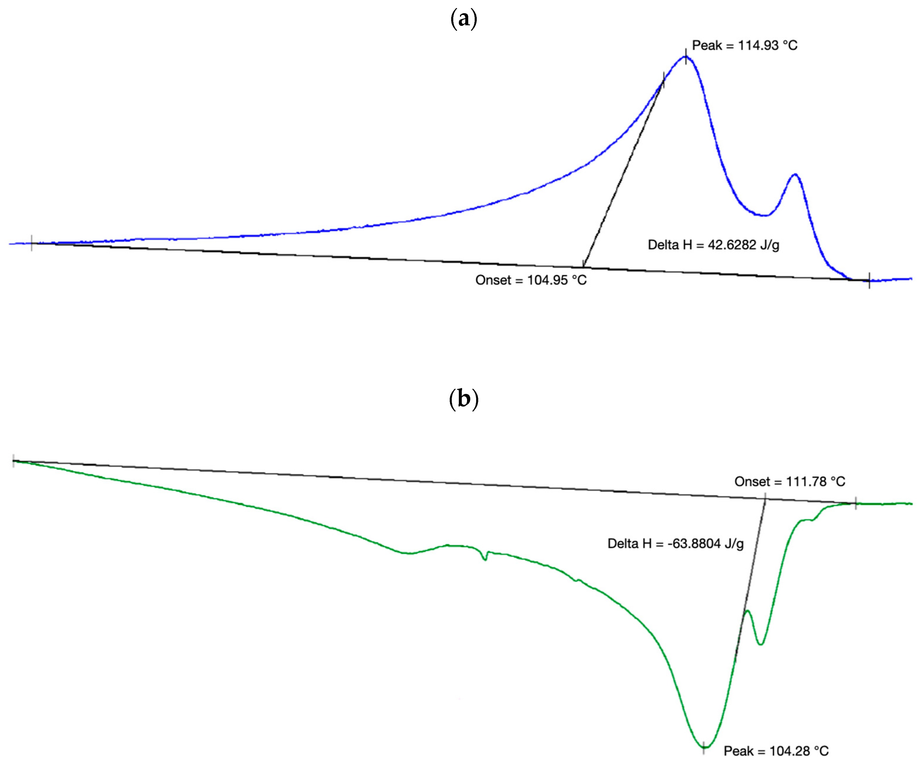
3.3. Differential Scanning Calorimeter

As shown in Figure 12a,b, the DSC analysis of the PAL filler revealed two distinct melting and crystallization phases of LDPE and LLDPE [51].
The onset, starting, ending, and peak temperatures for the melting and crystallization transitions of the LDPE, obtained from the heating and cooling cycle curves, respectively, and averaged across the five different samples, are reported in Table 3 and Table 4. These tables also present the specific enthalpy values, which refer to the total area of each curve, including the contributions from the LLDPE peak.
The degree of crystallinity was calculated from the values in Table 3 through Equation (1), resulting in χ = 11.25%.

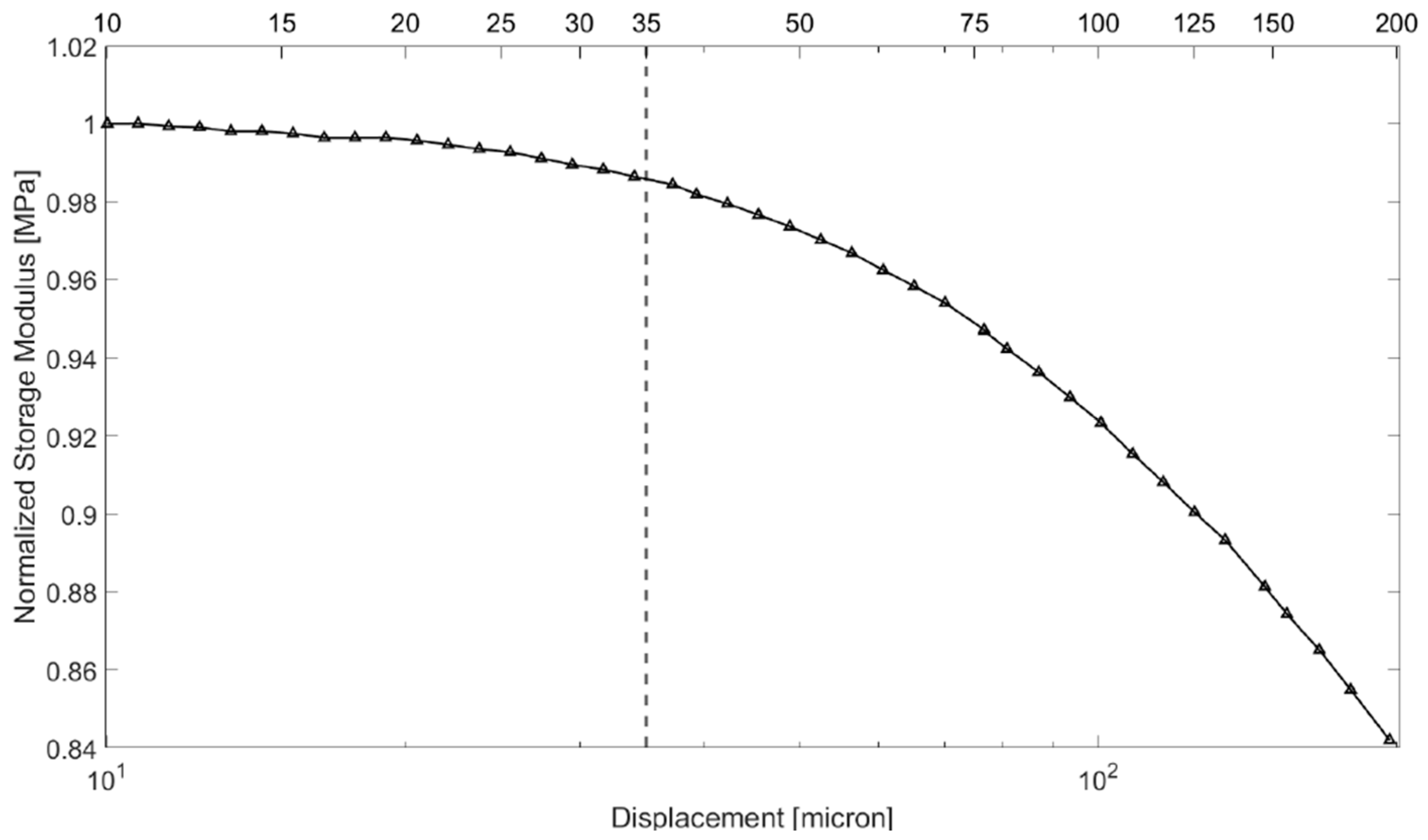
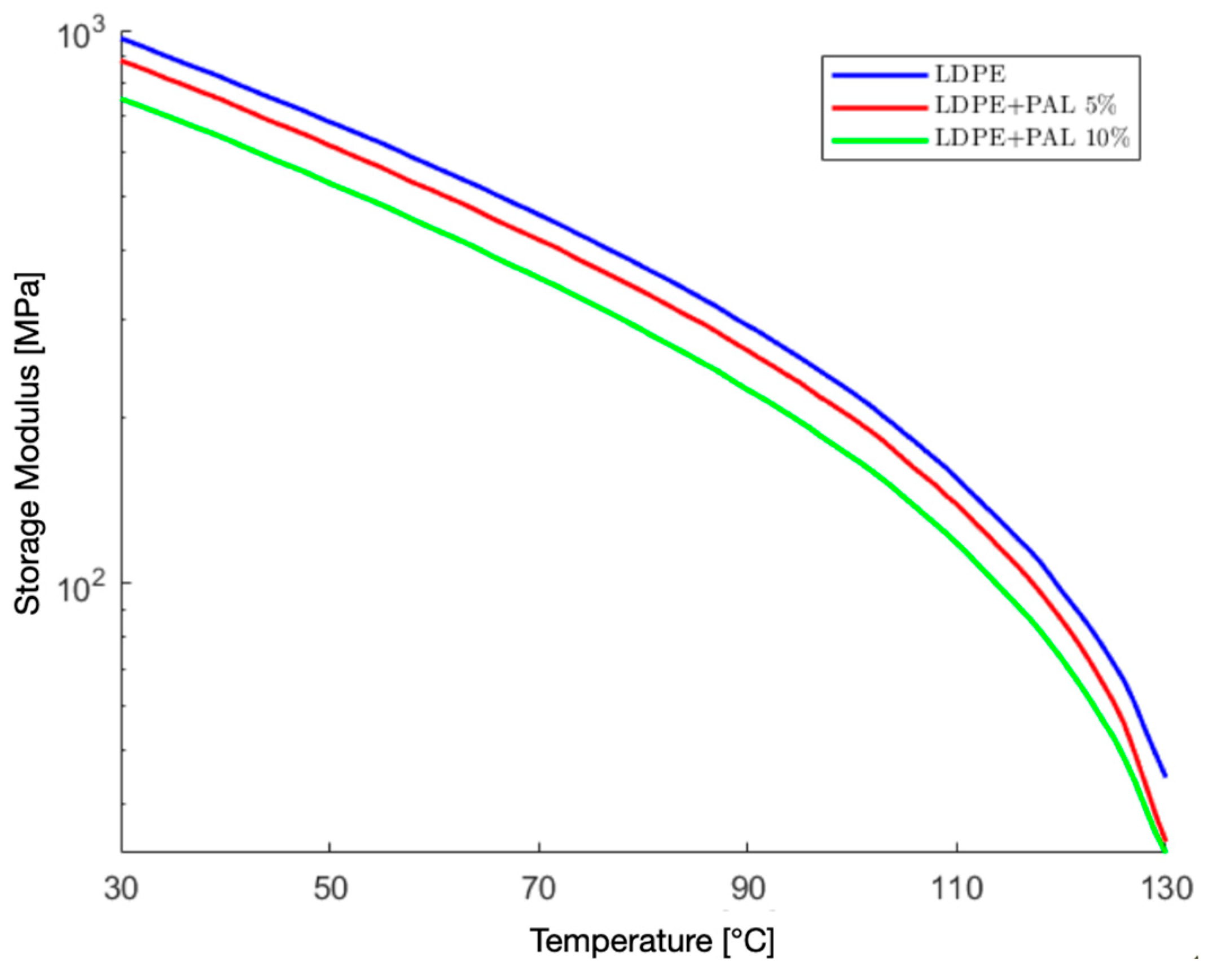
3.4. Dynamic Mechanical Analysis

This section presents the results of the DMA tests, reporting the temperature dependence of the average storage modulus and the loss modulus for all material types under investigation.
Figure 13 shows the storage modulus of the LDPE/PAL composites as a function of temperature for the filler contents of 5 wt% and 10 wt%, compared with that of the pristine LDPE. The inclusion of PAL filler in LDPE resulted in a reduction of the storage modulus for both PAL concentrations, with the effect becoming more pronounced at higher filler contents and temperatures. In particular, at room temperature, the pristine LDPE had a storage modulus of 1.04 GPa, which decreased by 8% to 0.96 GPa with the addition of 5 wt% PAL, and by 22% to 0.81 GPa with 10 wt% PAL. Similarly, at 80 °C, the storage modulus was 0.37 GPa for the pristine LDPE, 0.34 GPa for the LDPE with 5 wt% PAL, and 0.29 GPa for the LDPE with 10 wt% PAL, indicating reductions of 10% and 23%, respectively. At 120 °C, the storage modulus values were 97 MPa for the pristine LDPE, 86 MPa for the LDPE with 5 wt% PAL, and 73 MPa for the LDPE with 10 wt% PAL. This corresponds to reductions of 11% and 24% for 5 wt% and 10 wt% PAL, respectively, compared to the pure LDPE at the same temperature.
This decline in the storage modulus can be attributed to poor interfacial adhesion between the filler and the matrix. These findings demonstrate that the reduction in the storage modulus remained moderate (<25%) even when the material with 10 wt% filler loading was exposed to extreme temperatures, such as the ones experienced at the moon’s equator during the daytime.
Figure 14 shows the loss modulus of the pristine LDPE and LDPE/PAL composites as a function of the temperature. Each curve exhibits a peak at around 45 °C, which corresponds to the α-relaxation phenomenon [52]. While the α-peak appeared at the same temperature for all samples, its intensity varied, decreasing as the filler content increased. The maximum value of the loss modulus was 119 MPa for the pristine LDPE, 112 MPa for the LDPE with 5% PAL inclusions, and 97 MPa for the LDPE with 10% PAL inclusions.

3.5. Thermal Conductivity Analysis

Thermal conductivity measurements were conducted on the pristine LDPE and LDPE composites containing 5 wt% and 10 wt% of PAL filler.
At a controlled temperature of 23 °C, the pristine LDPE exhibited a thermal conductivity of 0.332 W/mK, aligning with the established values in the literature [53,54]. The incorporation of PAL filler into the LDPE matrix led to a substantial enhancement in the thermal conductivity. The 5 wt% LDPE/PAL composites demonstrated a thermal conductivity of 0.475 W/mK, representing a 43% increase over pure polyethylene. For the 10 wt% LDPE/PAL composites, the thermal conductivity continued to rise, reaching 0.513 W/mK, a 54.5% increase compared to the pristine material. These findings are reported in Table 5.
The observed increase in the thermal conductivity is primarily attributed to the presence of aluminum within the PAL trilaminate. Aluminum’s inherent high thermal conductivity, facilitated by the mobility of free electrons, created a continuous or semi-continuous network within the matrix. This network effectively facilitated heat transfer, leading to the observed enhancement in the thermal conductivity. Furthermore, aluminum’s greater density, compared to many polymers, enhances heat dissipation [55].

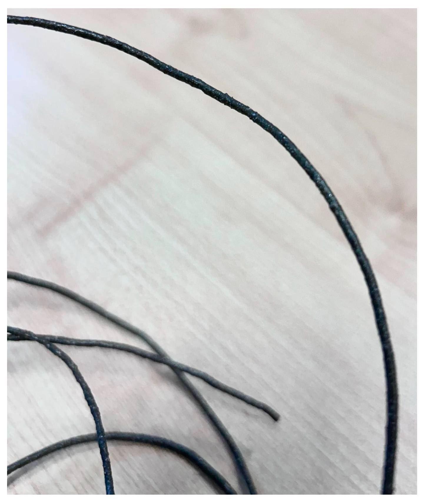
3.6. Extruded Filament

Figure 15 shows the filament fabricated by the extrusion of the 10 wt% LDPE/PAL composite materials. By measuring the diameter of the filament at the same cross-section but from different diametrically opposed points, the roundness of the section was verified. Repeating this operation on multiple sections along the longitudinal direction of the filament allowed for an assessment of the consistency of this roundness. The average diameter was found to be 1.74 ± 0.03 mm. The roundness and consistency of the cross-section were crucial to ensure that the 3D printing aligned with nominal parameters. Additionally, a visual inspection of the lateral surface of the filament showed no visible porosity, which is essential to prevent disruptions in material flow during printing and to maintain high printing quality [36].

4. Conclusions

This research aimed to enhance the recycling of space waste materials to enable the in-situ fabrication of new components. Focusing on beverage packaging waste, the study investigated the potential for developing a fully recycled composite material. The proposed composite consists of a low-density polyethylene (LDPE) matrix sourced from the septum adapter and straw of beverage containers, reinforced with the entirety of the packaging, which is typically made from PET-aluminum-LDPE trilaminate (PAL). Various characterization techniques, including mechanical and thermal property assessments, along with the extrusion process for fused filament production, were used to preliminarily investigate the material properties. The experimental results show that adding the PAL filler led to a reduction in the storage modulus, suggesting weaker interfacial adhesion between the matrix and filler. Notably, the inclusion of PAL filler also produced a substantial increase in the thermal conductivity, with the 10 wt% LDPE/PAL composites showing a 54.5% increase compared to the pristine LDPE. Given this notable boost in thermal conductivity (over 50% relative to the pristine LDPE), alongside a moderate modulus decrease (approximately 20% relative to the pristine LDPE), the LDPE-PAL composite with 10 wt% filler was chosen for extrusion into a suitable filament for 3D printing applications. The findings of this study are highly encouraging, indicating that the developed composite material holds significant potential for practical applications. Future research will concentrate on the fabrication of an initial prototype, with a specific focus on radiation shielding applications. This direction is motivated by the intrinsic radiation attenuation properties of LDPE/PAL composite materials. In fact, their constituents are known for their ability to absorb and scatter radiation, making the composite especially suitable for protective applications in space environments. This work could pave the way for more sustainable, in situ resource utilization in space missions, where effective radiation shielding is critical for safeguarding equipment and crew.

Author Contributions

Conceptualization, S.L.; methodology, S.L.; validation, F.D.R. and F.P.; formal analysis, F.D.R. and F.P.; investigation, F.D.R. and F.P.; resources, S.L.; data curation, F.D.R.; writing—original draft preparation, F.D.R. and F.P.; writing—review and editing, S.L.; supervision, S.L. All authors have read and agreed to the published version of the manuscript.

Funding

This work was financially supported by Sapienza University of Rome (grant number RG1221816C43DA9B). F.D. is grateful to the European Union—NextGenerationEU (National Sustainable Mobility Center CN00000023, Italian Ministry of University and Research Decree n. 1033—17/06/2022, Spoke 11—Innovative Materials and Lightweighting). The opinions expressed are those of the authors only and should not be considered as representative of the European Union or the European Commission’s official position. Neither the European Union nor the European Commission can be held responsible for them.

Data Availability Statement

The data will be made available upon request.

Conflicts of Interest

The authors declare that they have no known competing financial interests or personal relationships that could have appeared to influence the work reported in this paper.

Abbreviations

The following abbreviations are used in this manuscript:
ABSAcrylonitrile butadiene styrene
AMAdditive manufacturing
AMFAdditive manufacturing facility
ATRAttenuated total reflectance
DSCDifferential scanning calorimetry
DMADynamic mechanical analysis
FTIRFourier transform infrared spectroscopy
FFFFused filament fabrication
HDPEHigh-density polyethylene
IRInfrared radiation
ISMIn-space manufacturing
ISSInternational Space Station
LEOLow Earth orbit
LDPELow-density polyethylene
MISMade in space
NASANational Aeronautics and Space Administration
PALPET-aluminum-LDPE
SEMScanning electron microscopy
TUITethers Unlimited, Inc.

References

  1. Bizzarri, M.; Gaudenzi, P.; Angeloni, A. The biomedical challenge associated with the Artemis space program. Acta Astronaut. 2023, 212, 14–28. [Google Scholar] [CrossRef]
  2. Creech, S.; Guidi, J.; Elburn, D. Artemis: An overview of NASA’s activities to return humans to the Moon. In Proceedings of the 2022 IEEE Aerospace Conference (AERO), Big Sky, MT, USA, 5–12 March 2022; IEEE: Piscataway, NJ, USA, 2022. [Google Scholar]
  3. Von Ehrenfried, M. The Artemis Lunar Program Overview. In The Artemis Lunar Program: Returning People to the Moon; Springer: Cham, Switzerland, 2020; pp. 7–47. [Google Scholar]
  4. Hoffman, J.A.; Hinterman, E.R.; Hecht, M.H.; Rapp, D.; Hartvigsen, J.J. 18 Months of MOXIE (Mars oxygen ISRU experiment) operations on the surface of Mars—Preparing for human Mars exploration. Acta Astronaut. 2023, 210, 547–553. [Google Scholar] [CrossRef]
  5. de Curtò, J.; de Zarzà, I. Analysis of Transportation Systems for Colonies on Mars. Sustainability 2024, 16, 3041. [Google Scholar] [CrossRef]
  6. Zaccardi, F.; Laurenzi, S.; Santonicola, M. Shielding evaluation of polyethylene/regolith composites in the Martian radiation environment. In International Astronautical Congress: IAC Proceedings; International Astronautical Federation: IAF: Paris, France, 2021; Volume 2. [Google Scholar]
  7. SpaceX. Available online: https://www.spacex.com (accessed on 28 September 2024).
  8. Home/Blue Origin. Available online: https://www.blueorigin.com (accessed on 21 May 2024).
  9. Musk, E. Making Humans a Multi-Planetary Species. New Space 2017, 5, 46–61. [Google Scholar] [CrossRef]
  10. Musk, E. Making Life Multi-Planetary. New Space 2018, 6, 2–11. [Google Scholar] [CrossRef]
  11. Parker, J.S.; Ott, C.; Koehler, A.; Baskar, S.; Rosen, M.; Sullivan, T. Escape, plasma and acceleration dynamics explorers (escapade) mission design. In Proceedings of the 44th Annual American Astronautical Society Guidance, Navigation, and Control Conference, Breckenridge, CO, USA, 4–9 February 2022; Springer International Publishing: Cham, Switzerland, 2024. [Google Scholar]
  12. Burrows, W. The survival imperative: Using space to protect Earth. In Proceedings of the 2004 Planetary Defense Conference: Protecting Earth from Asteroids, Orange County, CA, USA, 23–26 February 2004. [Google Scholar]
  13. Szocik, K.; Reiss, M.J. Why space exploitation may provide sustainable development: Climate ethics and the human future as a multi-planetary species. Futures 2023, 147, 103110. [Google Scholar] [CrossRef]
  14. Jones, H.W. Take Material to Space or Make It There? ASCEND 2023, 2023, 4618. [Google Scholar]
  15. Anih, S. Crewed Space Mission Waste-Streams and Impact on Human Exploration of Mars. In Assessing a Mars Agreement Including Human Settlements; Springer International Publishing: Cham, Switzerland, 2021; pp. 129–146. [Google Scholar]
  16. Anih, S.I. Waste-Stream Management Optimization in Long-Duration Crewed Space Missions. Ph.D. Thesis, University of Cape Town, Rondebosch, South Africa, 2022. [Google Scholar]
  17. Olson, J.; Rinderknecht, D.; Essumang, D.; Kruger, M.; Golman, C.; Norvell, A.; Meier, A. A comparison of potential trash-to-gas waste processing systems for long-term crewed spaceflight. In Proceedings of the 50th International Conference on Environmental Systems, Lisbon, Portugal, 12–15 July 2021. [Google Scholar]
  18. Voyager Space|Nanoracks|Trash Deployment. Available online: http://voyagerspace.com/explore/bishop-airlock/ (accessed on 28 September 2024).
  19. Attaran, M. The rise of 3-D printing: The advantages of additive manufacturing over traditional manufacturing. Bus. Horiz. 2017, 60, 677–688. [Google Scholar] [CrossRef]
  20. Laurenzi, S.; Zaccardi, F.; Toto, E.; Santonicola, M.G.; Botti, S.; Scalia, T. Fused Filament Fabrication of Polyethylene/Graphene Composites for In-Space Manufacturing. Materials 2024, 17, 1888. [Google Scholar] [CrossRef]
  21. Kumar, L.J.; Nair, C.G.K. Current trends of additive manufacturing in the aerospace industry. In Advances in 3D Printing & Additive Manufacturing Technologies; Springer: Singapore, 2017; pp. 39–54. [Google Scholar]
  22. Hoffmann, M.; Elwany, A. In-space additive manufacturing: A review. J. Manuf. Sci. Eng. 2023, 145, 020801. [Google Scholar] [CrossRef]
  23. Singh, S.; Singh, G.; Prakash, C.; Ramakrishna, S. Current status and future directions of fused filament fabrication. J. Manuf. Process. 2020, 55, 288–306. [Google Scholar] [CrossRef]
  24. Prater, T.; Werkheiser, N.; Ledbetter, F.; Timucin, D.; Wheeler, K.; Snyder, M. 3D Printing in Zero G Technology Demonstration Mission: Complete experimental results and summary of related material modeling efforts. Int. J. Adv. Manuf. Technol. 2018, 101, 391–417. [Google Scholar] [CrossRef] [PubMed]
  25. Zocca, A.; Wilbig, J.; Waske, A.; Günster, J.; Widjaja, M.P.; Neumann, C.; Clozel, M.; Meyer, A.; Ding, J.; Zhou, Z.; et al. Challenges in the technology development for additive manufacturing in space. Chin. J. Mech. Eng. Addit. Manuf. 2022, 1, 100018. [Google Scholar] [CrossRef]
  26. Cushing, J.; Freedman, M.; Turner, K.; Muhlbauer, R.L.; Levedahl, B.; Slostad, J.; Hoyt, R.P.; Kim, T.; Werkheiser, M.J. Building a sustainable in-space manufacturing ecosystem: Positrusion and crissp. AIAA SPACE 2016, 2016, 5396. [Google Scholar]
  27. Prater, T.J.; Werkheiser, M.J.; Jehle, A.; Ledbetter, F.; Bean, Q.; Wilkerson, M.; Soohoo, H.; Hipp, B. NASA’s in-space manufacturing project: Development of a multimaterial fabrication laboratory for the international space station. In Proceedings of the AIAA SPACE and Astronautics Forum and Exposition, Orlando, FL, USA, 12–14 September 2017. [Google Scholar]
  28. Avcioğlu, S. LDPE matrix composites reinforced with dysprosium-boron containing compounds for radiation shielding applications. J. Alloys Compd. 2022, 927, 166900. [Google Scholar] [CrossRef]
  29. Zeb, J.; Arshad, W.; Rashid, A.; Akhter, P. Gamma Shielding by Aluminum (Al-Shielder Manual); No. PINSTECH—219; Pakistan Institute of Nuclear Science and Technology: Islamabad, Pakistan, 2010. [Google Scholar]
  30. Perchonok, M. The Challenges of Developing a Nutritious Food System for a Mars Mission; No. JSC-CN-31374; National Aeronautics and Space Administration: Washington, DC, USA, 2014. [Google Scholar]
  31. Kumar, L.; Gaikwad, K.K. Advanced food packaging systems for space exploration missions. Life Sci. Space Res. 2023, 37, 7–14. [Google Scholar] [CrossRef]
  32. Available online: https://www.goglioespress.com/medias/S4S.1001-PRT.pdf (accessed on 25 October 2024).
  33. NASA. NASA Handbook|Human Integration Design Handbook (HIDH)|NASA/SP-2010-3407/REV1; National Aeronautics and Space Administration: Washington, DC, USA, 2010.
  34. Fournier, R.; Persad, A.H. A low-cost adapter for the rehydration of commercially available food and beverages for spaceflight. Acta Astronaut. 2023, 210, 529–534. [Google Scholar] [CrossRef]
  35. Zaccardi, F.; Laurenzi, S.; Santilli, A.; Toto, E.; Santonicola, M. 3D printed polyethylene-based composites filled with Martian regolith simulant using fused filament fabrication. In International Astronautical Congress: IAC Proceedings; International Astronautical Federation: IAF: Paris, France, 2020. [Google Scholar]
  36. Zaccardi, F.; Toto, E.; Santonicola, M.G.; Laurenzi, S. 3D printing of radiation shielding polyethylene composites filled with Martian regolith simulant using fused filament fabrication. Acta Astronaut. 2022, 190, 1–13. [Google Scholar] [CrossRef]
  37. ImageJ—Image Processing and Analysis in Java. Available online: https://imagej.net/ij/ (accessed on 28 September 2024).
  38. Walton, W.H. Feret‘s statistical diameter as a measure of particle size. Nature 1948, 162, 329–330. [Google Scholar] [CrossRef]
  39. Zoubir, A.M.; Iskandler, D.R. Bootstrap methods and applications. IEEE Signal Process. Mag. 2007, 24, 10–19. [Google Scholar] [CrossRef]
  40. Tian, S.; Guo, Y.; Dong, Z.; Li, Z. Pore Microstructure and multifractal characterization of lacustrine oil-prone shale using high-resolution SEM: A case sample from natural Qingshankou shale. Fractal Fract. 2022, 6, 675. [Google Scholar] [CrossRef]
  41. Blaine, R.L. Thermal applications note. In Polymer Heats of Fusion; TA Instruments: New Castle, DE, USA, 2002. [Google Scholar]
  42. Vaniman, D.; Reedy, R.; Heiken, G.; Olhoeft, G.; Mendell, W. The lunar environment. Lunar Sourceb. 1991, 1, 27–60. [Google Scholar]
  43. Malla, R.B.; Brown, K.M. Determination of temperature variation on lunar surface and subsurface for habitat analysis and design. Acta Astronaut. 2015, 107, 196–207. [Google Scholar] [CrossRef]
  44. DeVieneni, A.; Velez, C.A.; Benjamin, D.; Hollenbeck, J. Cost-Effective Additive Manufacturing in Space: HELIOS Technology Challenge Guide; No. M12-2259; National Aeronautics and Space Administration: Washington, DC, USA, 2012. [Google Scholar]
  45. Smith, B. The infrared spectra of polymers, part I: Introduction. Spectroscopy 2021, 36, 17–22. [Google Scholar]
  46. Veerasingam, S.; Ranjani, M.; Venkatachalapathy, R.; Bagaev, A.; Mukhanov, V.; Litvinyuk, D.; Mugilarasan, M.; Gurumoorthi, K.; Guganathan, L.; Aboobacker, V.M.; et al. Contributions of Fourier transform infrared spectroscopy in microplastic pollution research: A review. Crit. Rev. Environ. Sci. Technol. 2020, 51, 2681–2743. [Google Scholar] [CrossRef]
  47. Kochetov, R.; Christen, T.; Gullo, F. FTIR analysis of LDPE and XLPE thin samples pressed between different protective anti-adhesive films. In Proceedings of the 2017 1st International Conference on Electrical Materials and Power Equipment (ICEMPE), Xi’an, China, 14–17 May 2017; IEEE: Piscataway, NJ, USA, 2017. [Google Scholar]
  48. Smith, B.C. The infrared spectra of polymers II: Polyethylene. Spectroscopy 2021, 36, 24–29. [Google Scholar] [CrossRef]
  49. Mahdavi, H.; Nook, M.E. Characterization and microstructure study of low-density polyethylene by Fourier transform infrared spectroscopy and temperature rising elution fractionation. J. Appl. Polym. Sci. 2008, 109, 3492–3501. [Google Scholar] [CrossRef]
  50. Djebara, M.; Stoquert, J.P.; Abdesselam, M.; Muller, D.; Chami, A.C. FTIR analysis of polyethylene terephthalate irradiated by MeV He+. Nucl. Instrum. Methods Phys. Res. Sect. B Beam Interact. Mater. At. 2012, 274, 70–77. [Google Scholar] [CrossRef]
  51. Dintcheva, N.; Jilov, N.; La Mantia, F. Recycling of plastics from packaging. Polym. Degrad. Stab. 1997, 57, 191–203. [Google Scholar] [CrossRef]
  52. Khanna, Y.P.; Turi, E.A.; Taylor, T.J.; Vickroy, V.V.; Abbott, R.F. Dynamic mechanical relaxations in polyethylene. Macromolecules 1985, 18, 1302–1309. [Google Scholar] [CrossRef]
  53. Lopes, C.M.; Felisberti, M.I. Thermal conductivity of PET/(LDPE/AI) composites determined by MDSC. Polym. Test. 2004, 23, 637–643. [Google Scholar] [CrossRef]
  54. Sabet, M.; Soleiman, H. Graphene Impact on Thermal Characteristics of LDPE. Polym. Sci. Ser. A 2019, 61, 922–930. [Google Scholar] [CrossRef]
  55. Lee, E.; Lee, S.; Shanefield, D.J.; Cannon, W.R. Enhanced Thermal Conductivity of Polymer Matrix Composite via High Solids Loading of Aluminum Nitride in Epoxy Resin. J. Am. Ceram. Soc. 2008, 91, 1169–1174. [Google Scholar] [CrossRef]
Figure 1. (a) Grinding mechanism of cross-section drafting; (b) grinding mechanism of slicing.
Aerospace 11 00957 g001
Figure 2. Components of the space beverage packaging: the packaging consists of a multilayer trilaminate structure, while the septum adapter, the straw, and the clamp are made of LDPE.
Aerospace 11 00957 g002
Figure 3. Scheme for the fabrication of LDPE/PAL composite specimens from surrogate packaging: shredding the trilaminate packaging material to reduce it to smaller, manageable pieces; sieving by a 60-mesh sieve to obtain uniformly sized particles of PAL; mixing the PAL particles with the LDPE matrix material to ensure uniform distribution of filler within the LDPE base; shaping the LDPE/PAL composite into test specimens using a casting technique; cooling and solidification, forming the final LDPE/PAL composite specimens.
Aerospace 11 00957 g003
Figure 5. Dynamical scanning curves of the trilaminate filler powder (the first heating cycle is in red; the cooling cycle, second heating cycle, and isothermal holdings are in black).
Aerospace 11 00957 g005
Figure 6. Top view of the opened chamber of the DMA-1, showing the single-cantilever operational mode configuration with the LDPE-PAL 5 wt% sample clamped.
Aerospace 11 00957 g006
Figure 7. Pristine LDPE displacement sweep.
Aerospace 11 00957 g007
Figure 8. Transmittance spectrum of LDPE side.
Aerospace 11 00957 g008
Figure 9. Transmittance spectrum of PET side.
Aerospace 11 00957 g009
Figure 10. (a) SEM image of trilaminate powder (scan speed of 6, magnification of 150×). (b) Image-J particle boundaries detected after image processing.
Aerospace 11 00957 g010
Figure 11. (a) Histogram of original sample set frequency of particle size based on 56 measurements. (b) Histogram of bootstrapped sample set frequency of average particle size based on 250 resamplings.
Aerospace 11 00957 g011
Figure 12. (a) Extrapolation of melting parameters from DSC curves. (b) Extrapolation of crystallization parameters from DSC curves.
Aerospace 11 00957 g012
Figure 13. Storage modulus as a function of temperature for pristine LDPE, LDPE-PAL 5wt%, and LDPE-PAL 10wt%.
Aerospace 11 00957 g013
Figure 14. Loss modulus as a function of temperature for pristine LDPE, LDPE-PAL 5 wt%, and LDPE-PAL 10 wt%.
Aerospace 11 00957 g014
Figure 15. Extruded filament of LDPE-PAL 10 wt%.
Aerospace 11 00957 g015
Table 1. Characteristic vibrational mode peak band assignments of LDPE.
Wavenumber (cm−1)Functional Group Modes
2916C–H stretching
2848C–H stretching
1462CH2 bending
1368CH2 wagging
730C–H rocking
718C–H rocking
Table 2. Characteristic vibrational mode peak band assignments of PET [50].
Wavenumber [cm−1]Functional Group Modes
2923CH2 stretching
1711 C=O stretching
1614 Parasubstituted benzene ring
1580 Benzene normal modes
1505 Parasubstituted benzene ring
1472 Trans CH2 bending
1409 Parasubstituted benzene ring
1339 CH2 wagging
1237 (C=O)–C stretching of ester
1092 O–CH2 stretching
1016 Parasubstituted benzene ring
968 Trans O–CH2 stretching
871 Ring C–H out of plane vibration
848 Trans CH2 rocking
791 C=O+CCO bending
720 Ring C–C bending and ring C–H out of plane
Table 3. DSC-extrapolated melting transition parameters of the trilaminate filler.
Onset temperature, Ton104.40 ± 0.56 °C
Starting temperature, Tst61.36 ± 12.45 °C
Ending temperature, Tee129.43 ± 3.78 °C
Peak temperature, Tmp113.41 ± 0.87 °C
Specific enthalpy, ΛHf32.97 ± 7.97 J/g
Table 4. DSC-extrapolated crystallization transition parameters of the trilaminate filler.
Onset temperature, Tc,on110.45 ± 2.55 °C
Starting temperature, Tc,st120.13 ± 1.62 °C
Ending temperature, Tc,ee20.37 ± 0.1 °C
Peak temperature, Tcp104.06 ± 0.46 °C
Specific enthalpy, ΛHc67.51 ± 5.24 J/g
Table 5. Thermal conductivity (λ) at 23 °C for pristine LDPE samples, LDPE with 5 wt% PAL, and LDPE with 10 wt% PAL.
Sampleλ [W ⋅ m−1 ⋅ K−1]
LDPE0.332
LDPE + PAL 5 wt%0.475
LDPE + PAL 10 wt%0.513
Disclaimer/Publisher’s Note: The statements, opinions and data contained in all publications are solely those of the individual author(s) and contributor(s) and not of MDPI and/or the editor(s). MDPI and/or the editor(s) disclaim responsibility for any injury to people or property resulting from any ideas, methods, instructions or products referred to in the content.

