
Experimental Verification of the Flexible Wheels for Planetary Rovers with the Push–Pull Locomotion Function

Abstract
1. Introduction
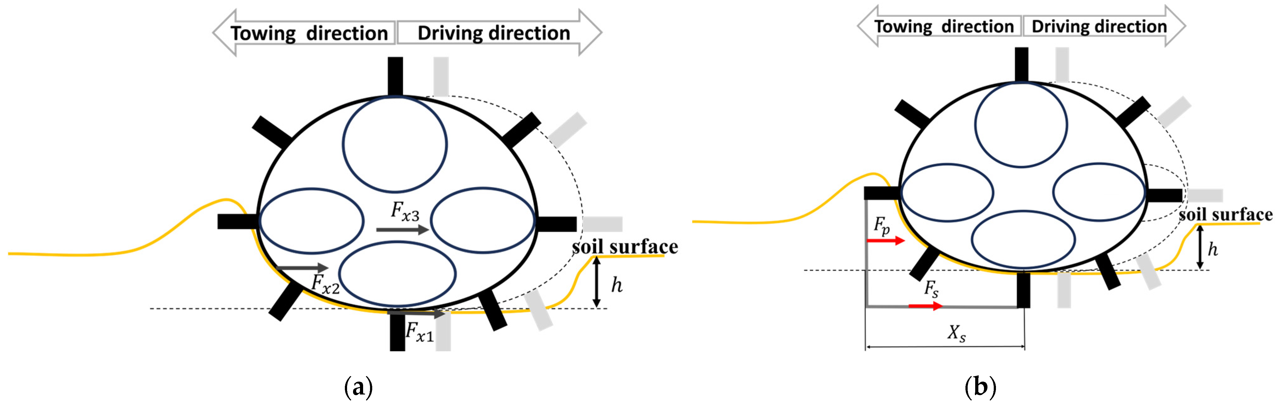
2. Support Force of Flexible Wheels
3. Single-Wheel Test
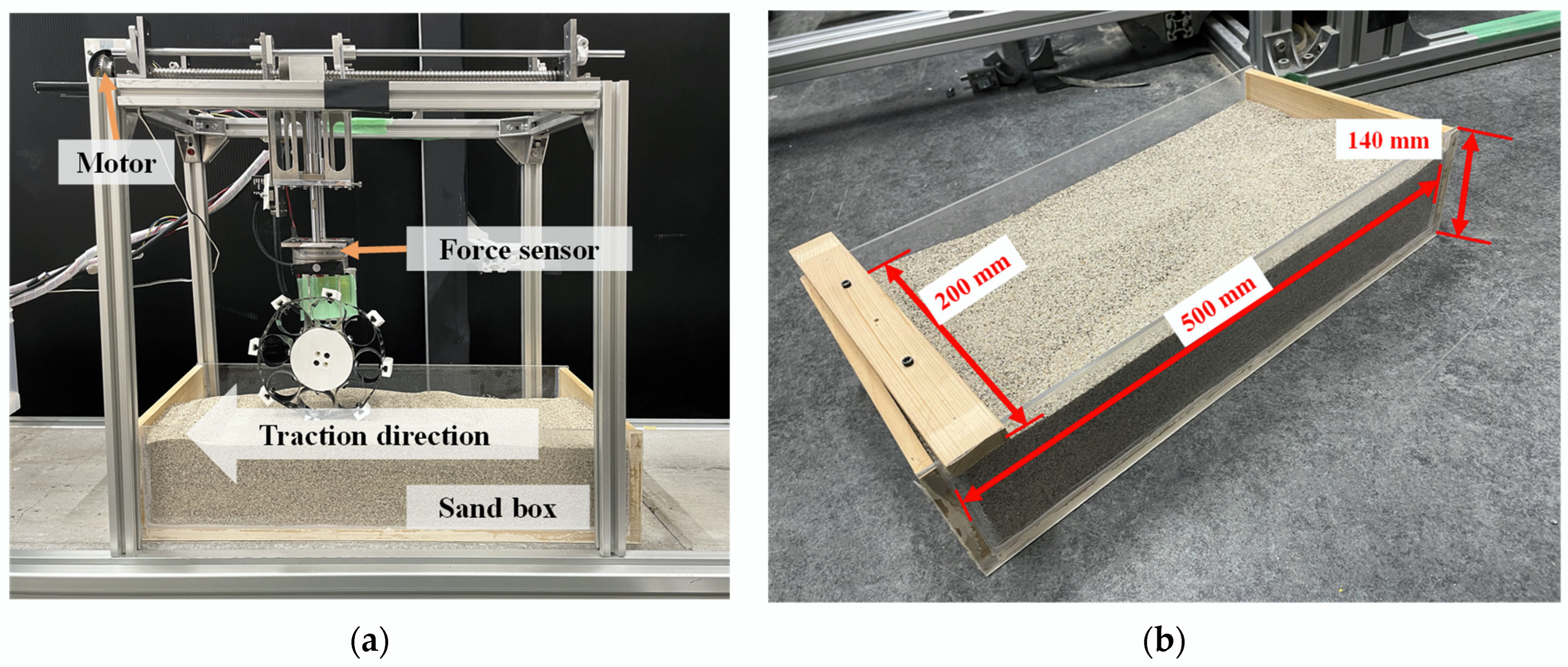
3.1. Single-Wheel Test Environment
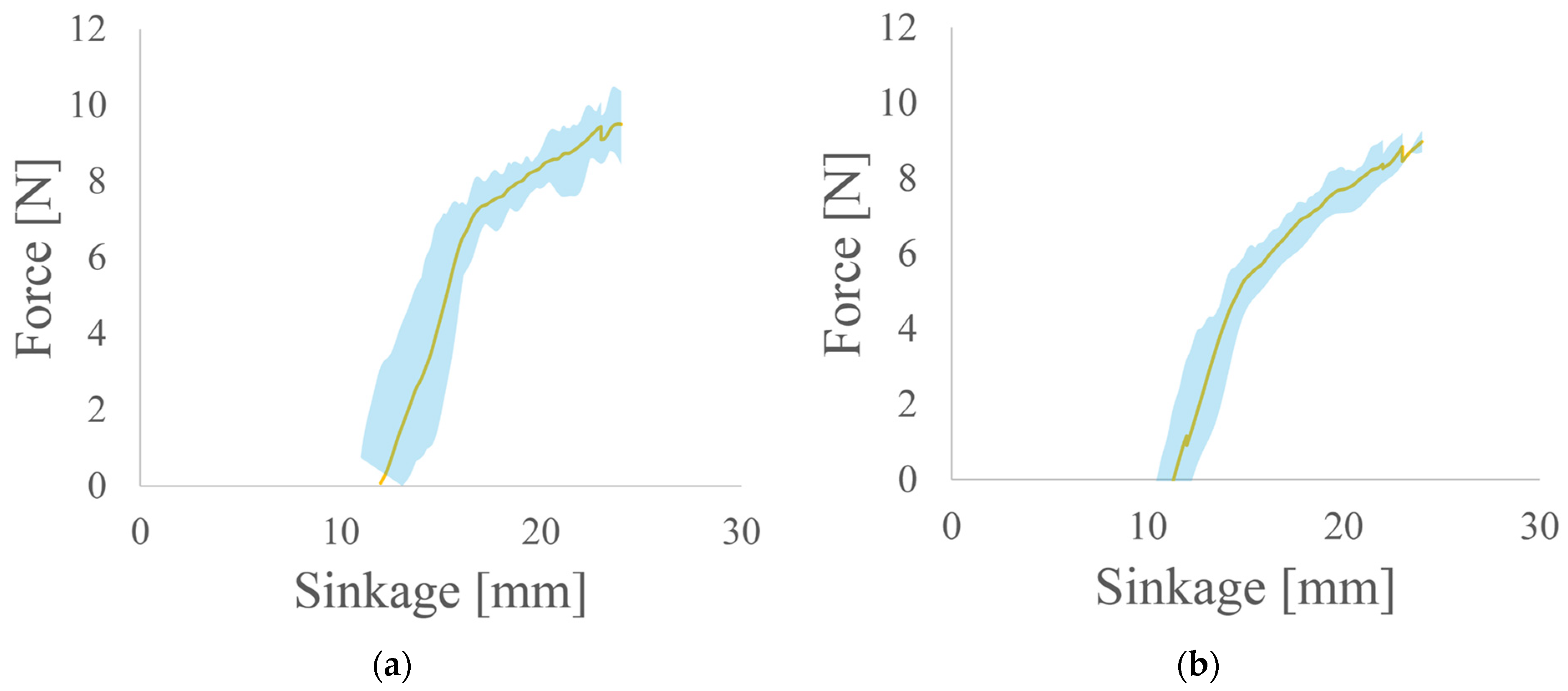
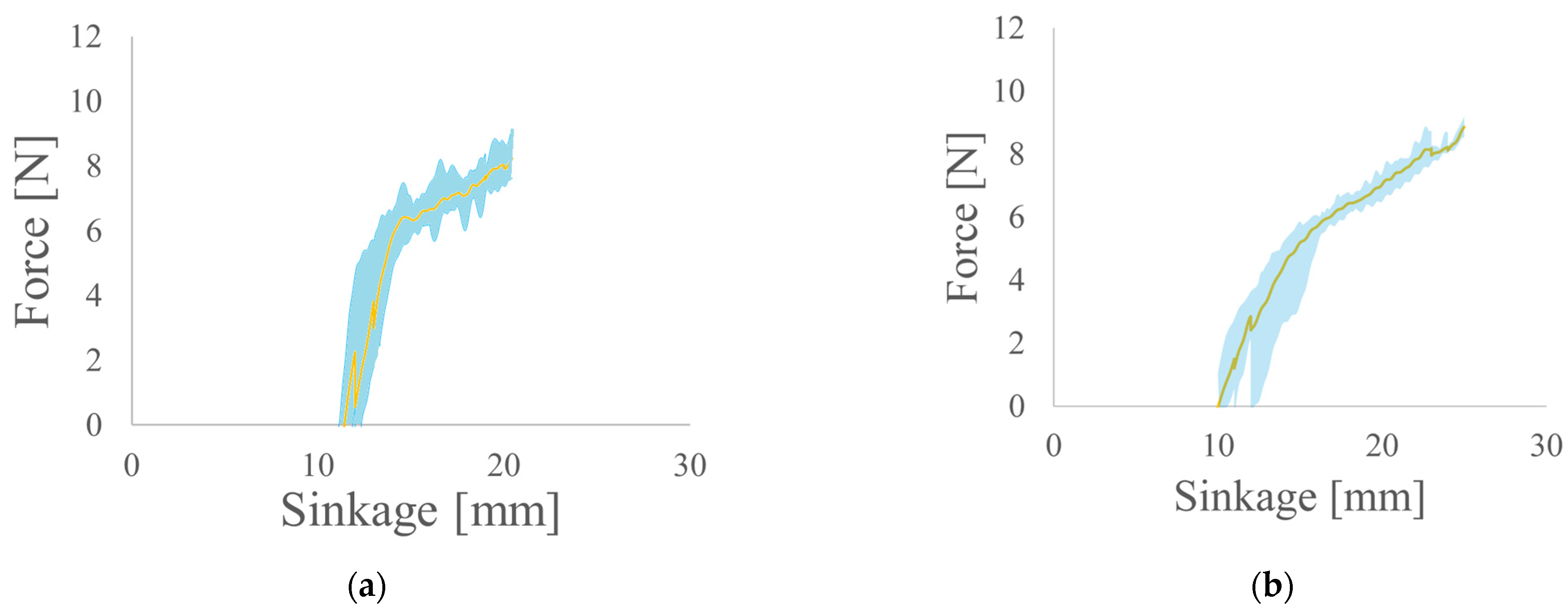
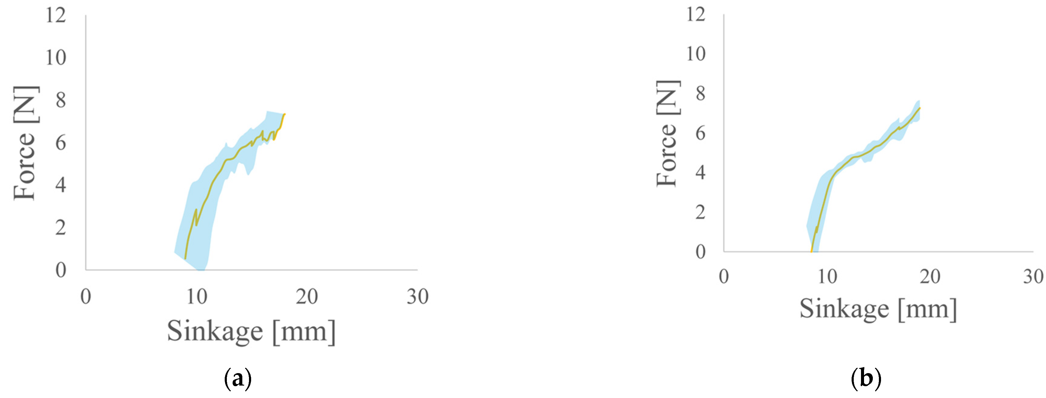
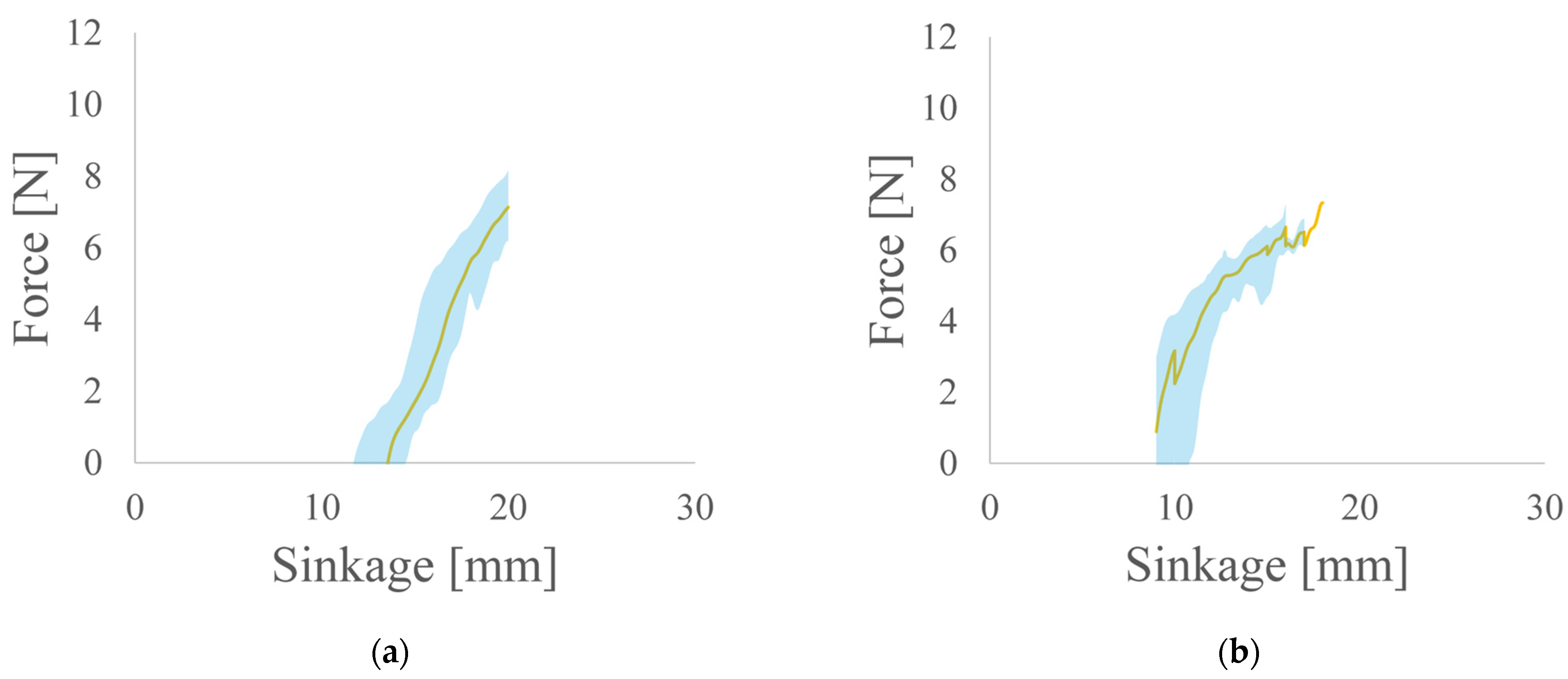
3.2. Results of Single-Wheel Test
4. Drivability Experiments
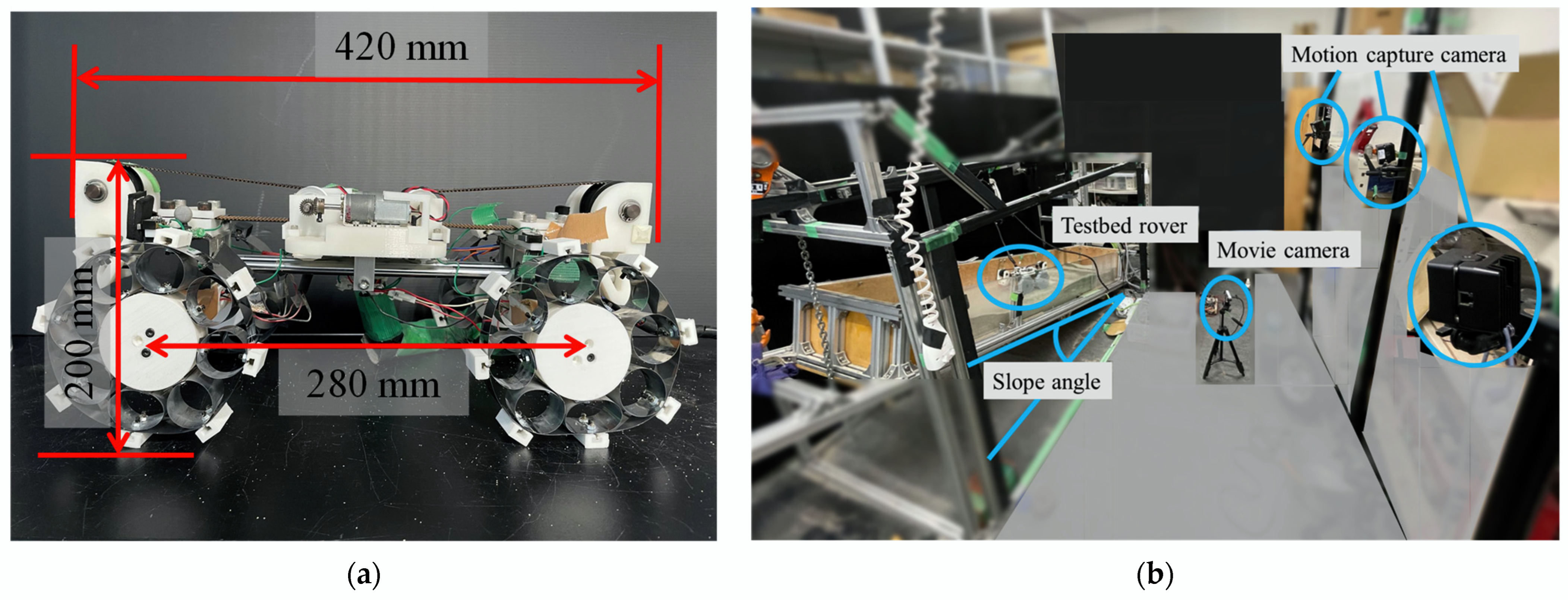
4.1. Drivability Experiments Environment
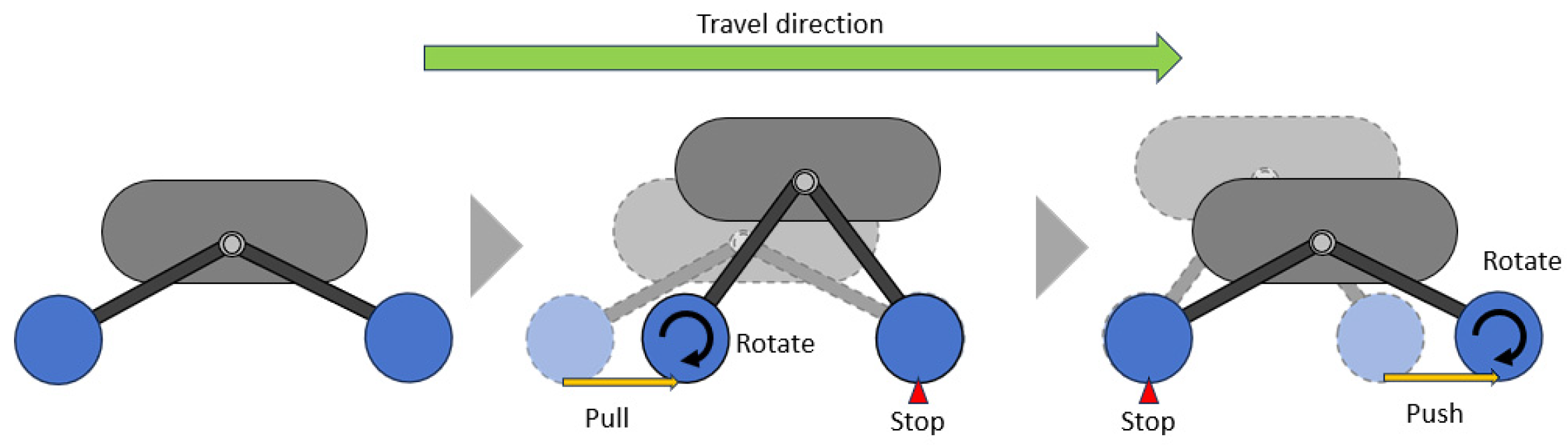
- Front wheel spinning and sinking.
- The rear wheel rotates when the front wheel is locked while the wheelbase decreases and the rear wheel pulls up.
- Rear wheel spinning and sinking.
- The front wheel rotates when the rear wheel is locked while the wheelbase expands and the front wheel pushes up.
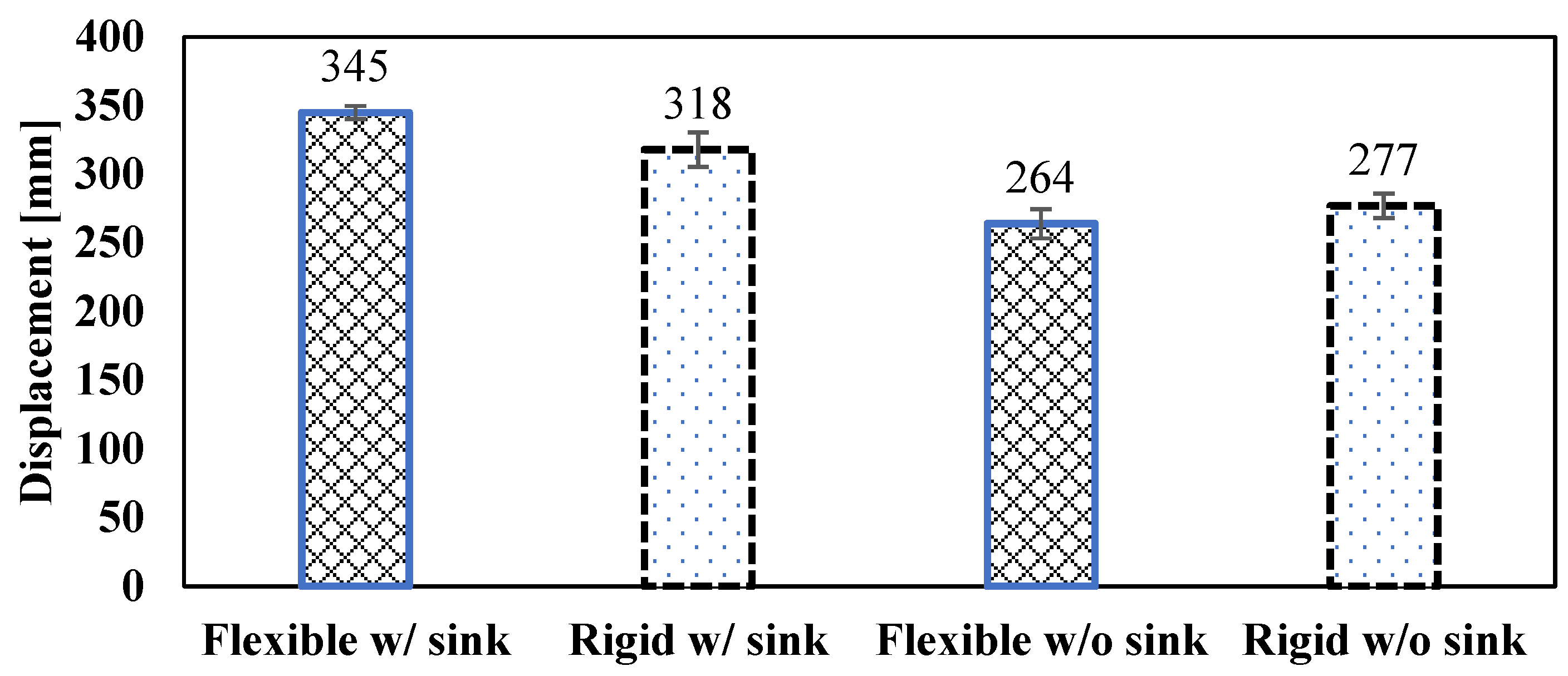
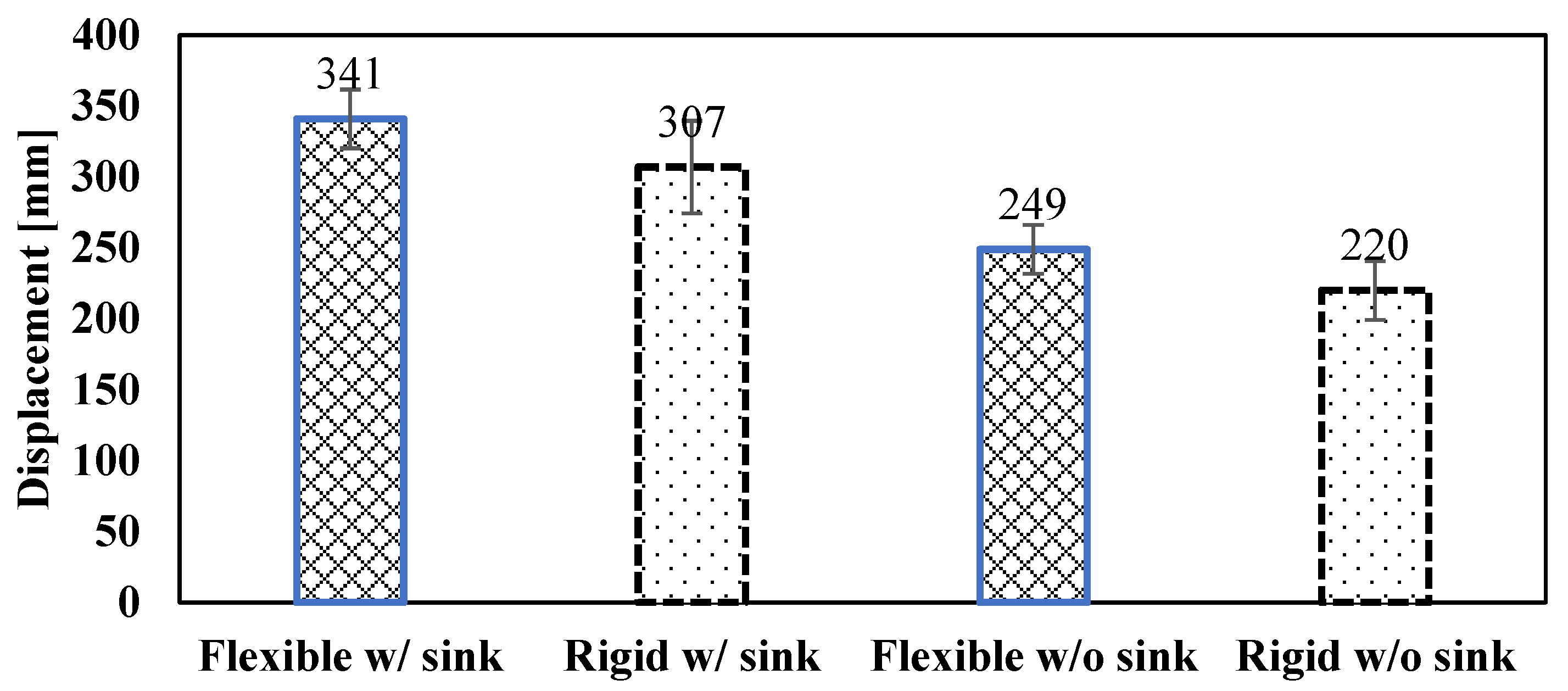
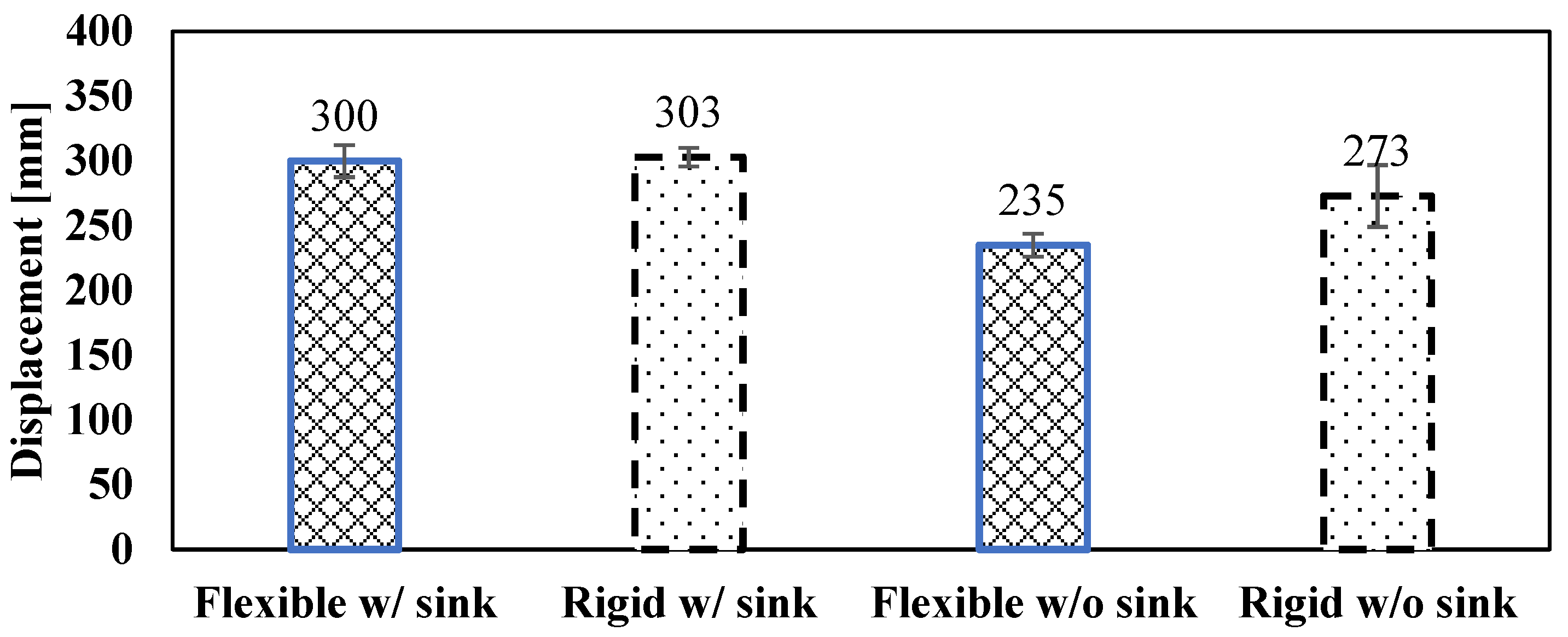
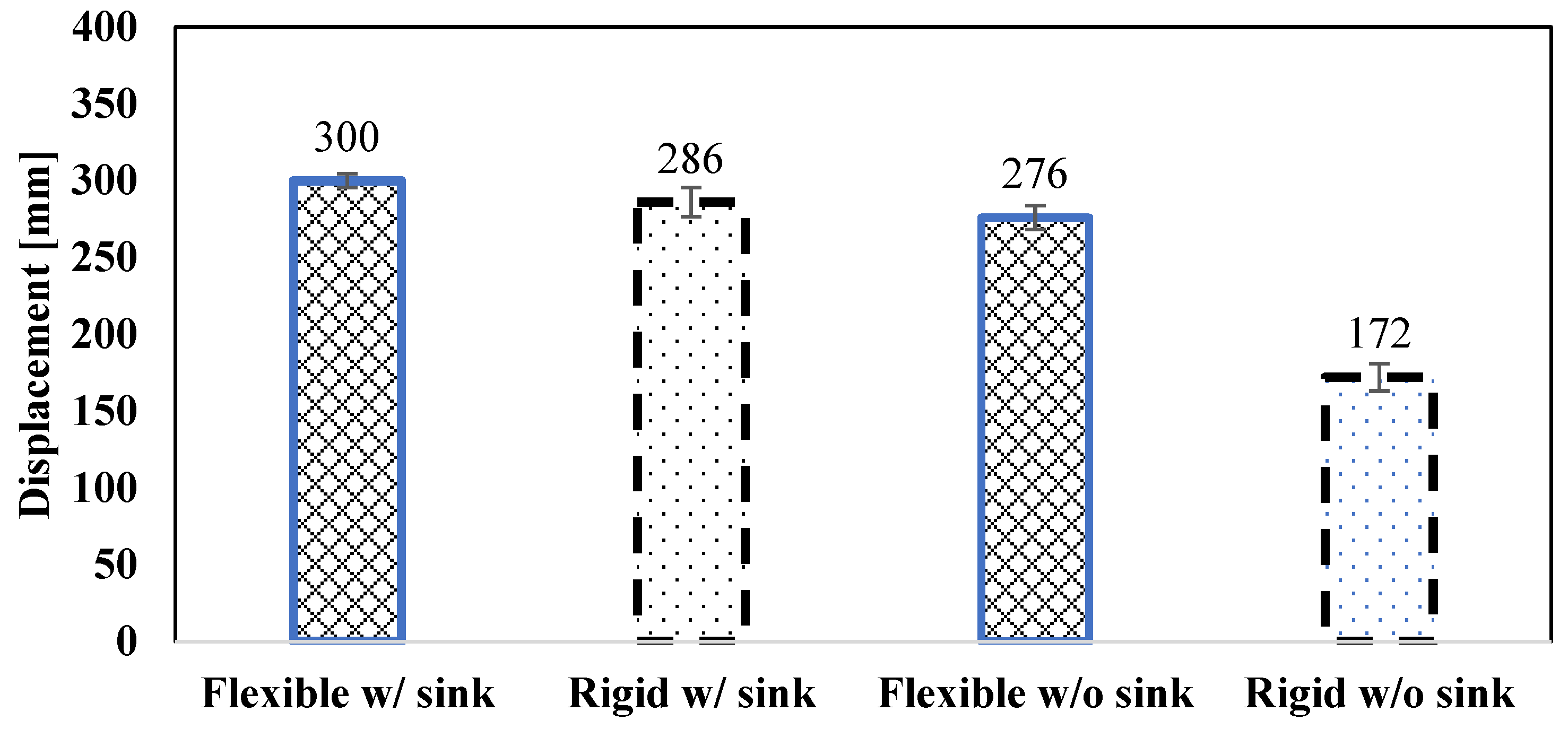
4.2. Results of the Drivability Experiments
5. Conclusions
- As lockable wheels, flexible wheels provide higher support.
- With certain parameters, the use of flexible wheels can replace the sinking action during push–pull locomotion.
- The impact of other parameters of the flexible wheels on driving performance remains to be verified.
Author Contributions
Funding
Data Availability Statement
Conflicts of Interest
References
- Yoshikawa, M.; Kawaguchi, J.; Fujiwara, A.; Tsuchiyama, A. The hayabusa mission. In Sample Return Missions; Elsevier: Amsterdam, The Netherlands, 2021; pp. 123–146. [Google Scholar]
- Maurel, C.; Gattacceca, J.; Uehara, M. Hayabusa 2 returned samples reveal a weak to null magnetic field during aqueous alteration of Ryugu’s parent body. Earth Planet. Sci. Lett. 2024, 627, 118559. [Google Scholar] [CrossRef]
- Kwan, C. A brief review of some interesting Mars rover image enhancement projects. Computers 2021, 10, 111. [Google Scholar] [CrossRef]
- Arvidson, R.E.; Bell, J.F., III; Bellutta, P.; Cabrol, N.A.; Catalano, J.G.; Cohen, J.; Crumpler, L.S.; Des Marais, D.J.; Estlin, T.A.; Farrand, W.H.; et al. Spirit Mars Rover Mission: Overview and selected results from the northern Home Plate Winter Haven to the side of Scamander crater. J. Geophys. Res. Planets 2010, 115, E00F03. [Google Scholar] [CrossRef]
- Bartlett, P.; Wettergreen, D.; Whittaker, W. Design of the Scarab Rover for Mobility & Drilling in the Lunar Cold Traps; Carnegie Mellon University: Pittsburgh, PA, USA, 2008. [Google Scholar]
- Liu, J.; Tan, M.; Zhao, X. Legged robots—An overview. Trans. Inst. Meas. Control. 2007, 29, 185–202. [Google Scholar] [CrossRef]
- Zhang, Y.; Huang, T. Research on a tracked omnidirectional and cross-country vehicle. Mech. Mach. Theory 2015, 87, 18–44. [Google Scholar] [CrossRef]
- Tanaka, T.; Hirose, S. Development of leg-wheel hybrid quadruped “AirHopper” design of powerful light-weight leg with wheel. In Proceedings of the 2008 IEEE/RSJ International Conference on Intelligent Robots and Systems, Nice, France, 22–26 September 2008; IEEE: Piscataway, NJ, USA, 2008; pp. 3890–3895. [Google Scholar]
- Michaud, F.; Letourneau, D.; Arsenault, M.; Bergeron, Y.; Cadrin, R.; Gagnon, F.; Legault, M.-A.; Millette, M.; Pare, J.-F.; Tremblay, M.-C.; et al. AZIMUT, a leg-track-wheel robot. In Proceedings of the 2003 IEEE/RSJ International Conference on Intelligent Robots and Systems (IROS 2003) (Cat. No.03CH37453), Las Vegas, NV, USA, 27–31 October 2003; Volume 3, pp. 2553–2558. [Google Scholar] [CrossRef]
- Creager, C.; Johnson, K.; Plant, M.; Moreland, S.; Skonieczny, K. Push-Pull Locomotion forvehicle extrication. J. Terramechanics 2015, 57, 71–80. [Google Scholar] [CrossRef]
- Fujiwara, D.; Iizuka, K.; Asami, D.; Kawamura, T.; Suzuki, S. Study on Traveling Performance for Variable Wheel-Base Robot Using Subsidence Effect. Int. J. Mech. Eng. Robot. Res. 2019, 8, 233–238. [Google Scholar] [CrossRef]
- Fujiwara, D.; Tsujikawa, N.; Oshima, T.; Iizuka, K. Analysis of a resistance force for the locked-wheel of push-pull locomotion rovers using large subsidence. J. Terramechanics 2021, 94, 1–12. [Google Scholar] [CrossRef]
- Iizuka, K.; Kubota, T. Study on locomotion systems of lunar exploration roverson loose soil. Stud. Sci. Technol. 2012, 1, 49–55. [Google Scholar]


| Description | Unit | Value |
|---|---|---|
| Slope angle | ° | 0 |
| Soil | - | Silica sand No. 5 |
| Load | N | 4.9 |
| Gear motor | - | HPCB 6V |
| 6-axis force sensor | - | SFS0128 |
| Motion capture system | - | OptiTrack |
| Motion capture software | - | Motive (version: 2.2.0) |
| Motion camera | - | Prime 13 |
| Modulus | Value | Unit | Name of Parameters |
|---|---|---|---|
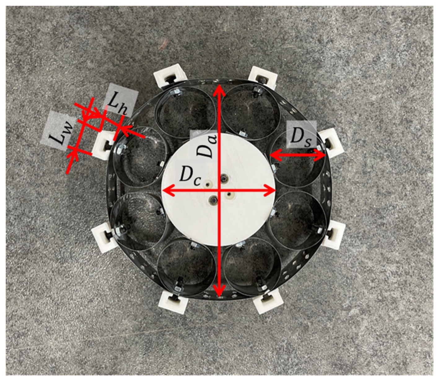
| 120 | mm | Diameter of wheel | |
| 60 | mm | Diameter of center part | |
| 30 | mm | Diameter of spoke | |
| 25 | mm | Width of wheel | |
| 8, 16, 24 | - | Number of lugs | |
| 7, 14 | mm | Width of lug | |
| 9 | mm | Height of lug |
| 8_7 mm(F) | 8_7 mm(R) | 16_7 mm(F) | 16_7 mm(R) | 24_7 mm(F) | 24_7 mm(R) | 8_14 mm(F) | 8_14 mm(R) | |
|---|---|---|---|---|---|---|---|---|
| Force [N] | 8.459 | 7.782 | 8.060 | 7.081 | 6.848 | 7.136 | 7.147 | 7.204 |
| Slope [N] | 0.968 | 0.917 | 1.036 | 0.757 | 0.877 | 0.699 | 1.002 | 0.764 |
| Modulus | Value | Unit | Name of Parameters |
|---|---|---|---|
| (max) | 280 | mm | Maximum wheelbase length |
| (min) | 160 | mm | Minimum wheelbase length |
| 60 | mm | Wheel radius | |
| - | 145 × 420 × 200 | mm | Rover width, length, and height |
| 140 | mm | Length between the center of gravity and front wheel center | |
| 140 | mm | Length between the center of gravity and rear wheel center |
| Description | Unit | Value |
|---|---|---|
| Slope angle | ° | 25 |
| Soil | - | Silica sand No. 5 |
| Motion capture system | - | OptiTrack |
| Motion capture software | - | Motive (version: 2.2.0) |
| Motion camera | - | Prime 13 |
| Calibration wand | - | CW-500 |
| Calibration square | - | CS-200 |
Disclaimer/Publisher’s Note: The statements, opinions and data contained in all publications are solely those of the individual author(s) and contributor(s) and not of MDPI and/or the editor(s). MDPI and/or the editor(s) disclaim responsibility for any injury to people or property resulting from any ideas, methods, instructions or products referred to in the content. |
© 2024 by the authors. Licensee MDPI, Basel, Switzerland. This article is an open access article distributed under the terms and conditions of the Creative Commons Attribution (CC BY) license (https://creativecommons.org/licenses/by/4.0/).
Share and Cite
He, Q.; Fujiwara, D.; Iizuka, K. Experimental Verification of the Flexible Wheels for Planetary Rovers with the Push–Pull Locomotion Function. Aerospace 2024, 11, 1033. https://doi.org/10.3390/aerospace11121033
He Q, Fujiwara D, Iizuka K. Experimental Verification of the Flexible Wheels for Planetary Rovers with the Push–Pull Locomotion Function. Aerospace. 2024; 11(12):1033. https://doi.org/10.3390/aerospace11121033
Chicago/Turabian StyleHe, Qingze, Daisuke Fujiwara, and Kojiro Iizuka. 2024. "Experimental Verification of the Flexible Wheels for Planetary Rovers with the Push–Pull Locomotion Function" Aerospace 11, no. 12: 1033. https://doi.org/10.3390/aerospace11121033
APA StyleHe, Q., Fujiwara, D., & Iizuka, K. (2024). Experimental Verification of the Flexible Wheels for Planetary Rovers with the Push–Pull Locomotion Function. Aerospace, 11(12), 1033. https://doi.org/10.3390/aerospace11121033