1. Introduction
Since the origin of the jet engine, significant effort has been made to enhance engine designs and better understand their flow physics to improve their efficiency, reduce environmental impact, and reduce noise. Initial research performed on the turbomachinery components found in these engines was directed at addressing these important issues. The resulting discoveries helped drive further innovation in instrumentation, manufacturing methods, and computational predictions and influenced the development of more complex turbomachinery designs. As these tools and methods have become more advanced and reliable, research efforts have had to keep pace and evolve to interpret the difficulties associated with more sophisticated designs.
Many complexities arise as modern aero engine designs push towards smaller, more highly loaded compressor cores. For example, tip clearance effects become important to understand and manage as blade size is reduced in these smaller cores. Additionally, decreased axial spacing increases the intensity of blade-row interactions and aeromechanical considerations, further exacerbated by the higher rotational speeds required to deal with higher loading levels. As a result, while low-speed research rigs were once crucial to observing and understanding flow phenomena at relatively low cost and risk, today’s challenges require high-speed research rigs, often incorporating multiple stages and featuring small-core geometry. Furthermore, to help better predict and understand the phenomena associated with these more complex designs, the demand for experimental data has become increasingly valuable as designers seek to validate their computational models to save time, effort, and money.
With few multistage research facilities capable of matching engine representative Reynolds numbers and Mach numbers, the Purdue 3-Stage (P3S) Axial Compressor Research Facility has established a unique niche investigating the previously mentioned research areas. Over the past few decades, the facility has contributed to significant research in the global turbomachinery community by improving and developing research and instrumentation practices performed in an original and realistic flow field environment. Experimental investigations into blade-row interactions, vane clocking effects, tip leakage flows, stator leakage flows, stall-inception, and instrumentation development with the original compressor design (denoted PAX100) have been crucial to building an understanding of the aerodynamic performance and aeromechanical influence associated with the current facility and multistage compressors. Finally, the results from these investigations have also provided an extensive database for validating computational fluid dynamics tools.
In addition to these thoroughly established capabilities and research methods, upgrading the facility for future compressor designs (PAX200) allows for further development in understanding the loss mechanisms found in small-core axial compressors and the validation of novel component designs emphasizing desensitization to large relative tip clearances.
This paper begins with the historical background of the facility as an industry research compressor before transitioning to academic research prior to Purdue University. Next, the transfer of the compressor facility to Purdue University and its early development, including significant growing pains, are described. Important developments and a renovation of the facility, including driveline reversal and increased instrumentation capabilities, are documented, along with descriptions of the research enabled by these improvements. Finally, the challenges and required improvements associated with the nearly five times increase in power requirement of 1400 HP (1 MW) and factor of 1.6 increase in rotational speed are explored.
2. Historical Background (1985–1998)
What is known today as the Purdue 3-Stage (P3S) Compressor Research Facility got its academic start at Iowa State University. The facility began with the donation of a three-stage compressor from Pratt & Whitney/United Technologies Research Center (UTRC) with all components necessary for its successful operation (support structure, driveline, gearbox, motor, etc.). The compressor design supported the UTRC JT-9D engine program in the late 1970s and featured five different blade row configurations incorporating slight geometric alterations in blading and options for shrouded and cantilevered stators. After completing the engine program at UTRC, the compressor design and driveline components were given to Iowa State University’s Turbomachinery Components Research Laboratory, directed by Professor Theodore Okiishi, where it was installed and commissioned in 1985 [
1].
As assembled at Iowa State University [
2] and shown in
Figure 1, the facility was driven from the front by a Westinghouse 500 HP DC Cradle Dynamometer with a speed range of 800 to 3000 RPM. A complete electronic drive system using the MaxPak Plus rectifier/controller, procured from Reliance Electric, powered the drive motor, regulating it to within 0.01% of its maximum speed. Additionally, a Western Gear speed-increasing gearbox (2.51:1) further increased the compressor rotational speed to meet the compressor design speed.
Support brackets were installed to couple the compressor shaft to the gearbox, and bearings were added midway across the four-foot span to increase driveline support and address issues with shaft dynamics. Ambient, outdoor air entered the facility through a duct from the ceiling and passed through a filter. The filtered air then circulated the driveline to enter a bellmouth, followed by a honeycomb and the inlet of the compressor section. At the exit of the compressor, an axially controlled conical throttle regulated the back pressure before the exhaust air passed through an additional air collector and discharge duct and was finally expelled back to ambient conditions through the ceiling.
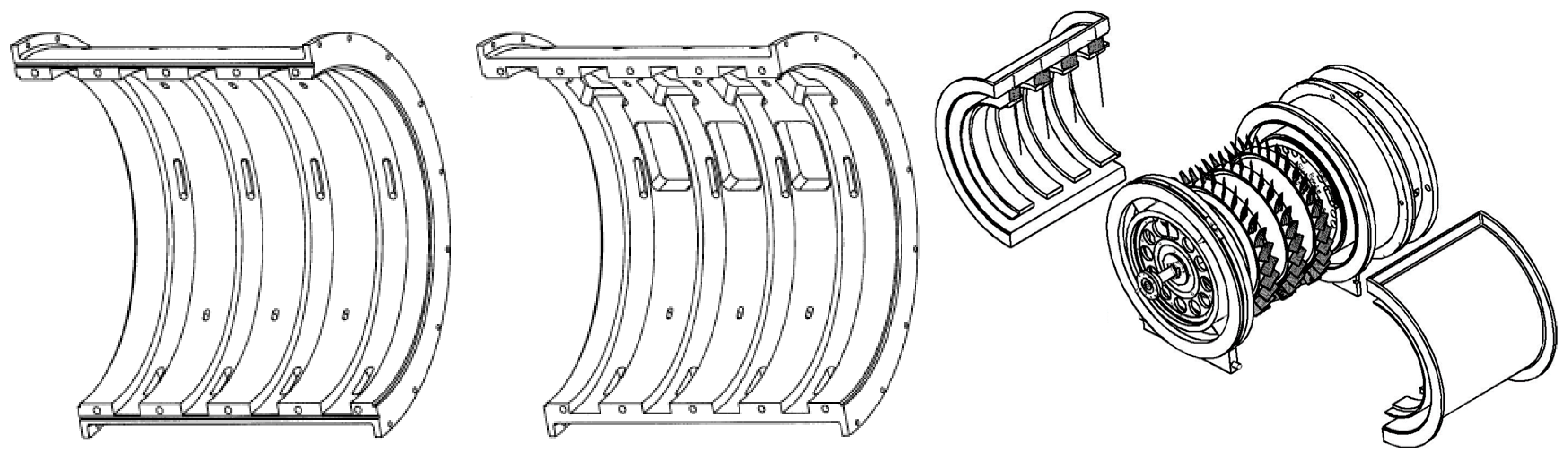
The compressor was assembled vertically by stacking each blade row in sequence and compressed together using four compression rods spanning the length of the compressor. The concentricity of the shaft and rotor drum within the compressed casing was achieved by adjusting the front and rear structural supports containing the bearing housings. The assembled machine was then rotated horizontally and installed in the facility. The primary compressor design featured a hub-shrouded inlet guide vane (IGV) with three stages of adjustably staggered cantilevered blade rows in a converging annulus. The overall compressor design specifications are in
Table 1.
At Iowa State University, under Professor Theodore Okiishi, this compressor was used for detailed aerodynamics studies and to better understand the flow physics observed in high-speed, multistage, axial compressors. For example, one such study researched the effects of compressibility and rotational speed on improving the stall margin of multistage, axial-flow compressors, specifically by varying the stationary blade angles upstream of each rotor [
3].
3. Establishing the P3S Compressor Research Facility
3.1. The Fleeter/Lawless Era (1998–2007)
As Professor Okiishi’s research focus shifted to projects at NASA Glenn Research Center, such as [
4], the Iowa State University facility became less utilized. Knowing Professor Sanford Fleeter and Professor Patrick Lawless had developed a strong research program in experimental compressor work, arrangements were made to transfer the compressor to Purdue University. Their expertise in compressor aerodynamics and aeromechanics investigations provided a perfect opportunity for the Pratt & Whitney compressor to reach its full potential and impact on high-speed, multistage, axial compressor research.
3.2. Move to Purdue University (1998–2000) [5]
While the Pratt & Whitney compressor design and structural components shipped from Iowa State University to Purdue University, many driveline components were left behind as they were too large for the new facility. The search for a replacement drivetrain system resulted in a 2400VAC Siemens induction motor installation capable of delivering 600 HP to the compressor at a constant speed of 1776 RPM. A Transfluid KSL-24 viscous coupling transmitted torque and controlled the shaft speed of the compressor through a Cotta speed-increasing gearbox. With a ratio of 3.46:1, the front-driven compressor could reach speeds of up to 6145 RPM after accounting for the inherent slip of the speed variation in the viscous fluid coupling. A shaft extension separated the compressor from the gearbox to produce a cleaner, more uniform inlet flow, and a structure supporting the extended shaft length was installed. In addition, universal joint couplings were installed at each end of the extension to account for any slight misalignment.
With a viscous coupling and gearbox, cooling systems were necessary to counteract the oil temperature increase associated with the friction and pump work of the facility components used to drive the compressor. A water tower outside the laboratory provided the cooling requirements for the oil-water heat exchangers during compressor operation. Atmospheric air was drawn into the test cell through doors in the building, and wire-reinforced polyester panels filtered the air entering the compressor. The filtered air flowed around the driveline components into the bellmouth and then through the compressor. A new, sliding conical throttle, powered by a Minarak RG500 UA DC controller, closed off the flow path to achieve the desired mass flow rate. After the throttle, the exhaust air passed into a long, steel duct with a perforated plate to fully dissipate the jet of exhaust air into a fully turbulent and symmetric profile to accurately quantify the mass flow rate through a flowmeter before exhausting through the side of the building.
Many instrumentation systems were also added to monitor the health of the compressor and capture aerodynamic measurements. Bearing temperatures were obtained using K-type thermocouples held against the bearing housing, and both pressure and temperature measurements monitored the heat exchanger/cooling systems for the gearbox and viscous coupling. Stagnation temperatures were measured at the inlet to the IGV, exit of S3, and within the exhaust duct. Static pressures distributed throughout the compressor casing and a pitot-static probe in the exhaust provided measurements for determining the mass flow rate. Accelerometers mounted on the compressor casing in both the horizontal and vertical planes monitored vibrations, and a tachometer recorded rotational speed through a 1/rev signal from the gearbox shaft.
Shortly after the commissioning of the compressor at its new home, the facility suffered its first failure, a reminder of the inherent complexities of high-speed, high-power turbomachinery testing. Debris ingested into the compressor inlet damaged the airfoils of all blade rows. An investigation showed that the gearbox had shifted during the initial mechanical checkout tests, creating a misalignment between the viscous coupling and compressor, causing excitation in the shaft. As a result, the shaft contacted the shaft guard, destroying the guard, the shaft extension, universal joint couplings, and needle bearings, with some of the pieces ingested by the inlet of the compressor. The blade rows were destroyed, but the facility was rebuilt using salvaged, undamaged hardware. However, upgrades were still required to fix the driveline elements causing the failure to ensure safe operation and minimize the risk of further damage reoccurring.
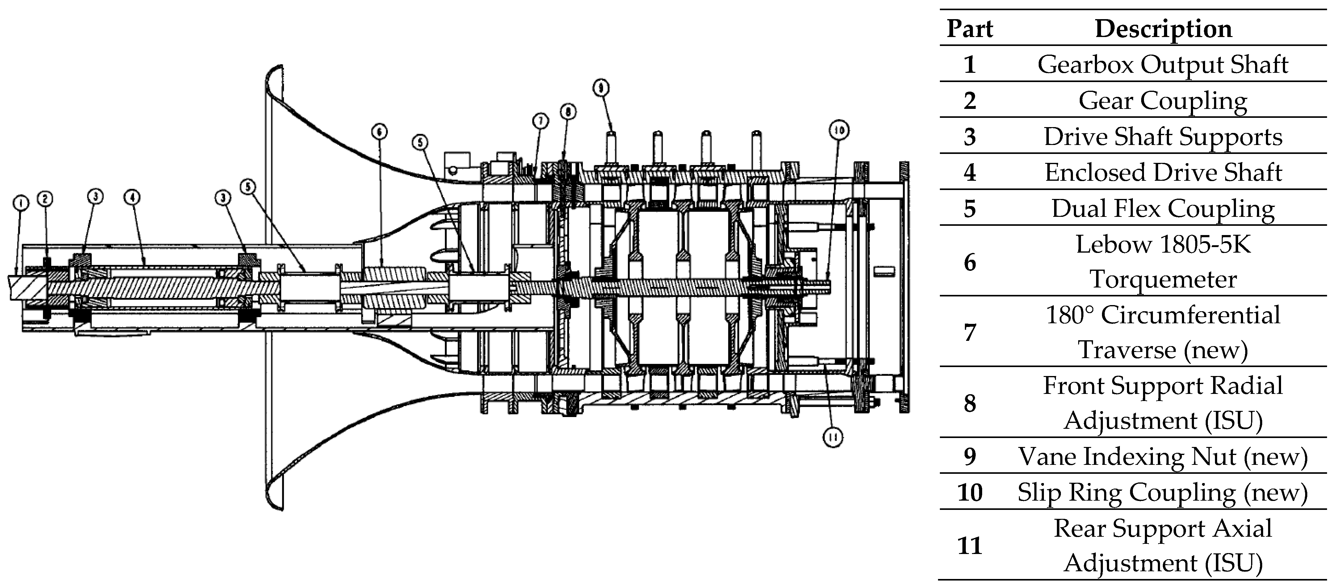
Lovejoy HFS-2 gear couplings replaced the universal joint couplings between the compressor and gearbox in the original driveline to provide smoother power transmission and remove small components susceptible to ingestion. In addition, installing a pneumatically actuated caliper brake and disc prevented sudden accelerations between the viscous fluid coupling and gearbox—an issue prevalent in the old driveline configuration. Other improvements included a coil layer around the shaft guard for further debris containment in case of future failure and the stiffening of the gearbox mounting base to prevent movement. Finally, after realigning the compressor and gearbox shafts, a Lebow 1805-5K torquemeter, mounted to a supporting bridge structure and connected in series with flexible disc couplings, spanned the driveline between the high-speed gearbox shaft and the compressor shaft, resulting in the finished facility in
Figure 2.
3.3. The Beginning of the Purdue University and Rolls-Royce Corporation (2000–2003) [6]
Around the same time as the facility failure and updates to the driveline, Rolls-Royce and Purdue University were awarded a grant through the 21st Century Research and Technology Development Fund—legislation created by the Indiana General Assembly to help stimulate and diversify the state’s economy through investment in advanced technologies. This award allowed the design and manufacturing of a new compressor, designed by Rolls-Royce and later denoted PAX100, to be installed in the P3S facility. The compressor modeled the last three stages of a Rolls-Royce engine core, rescaled to allow integration into the existing facility and provide ample instrumentation access into the flow path for measurements while minimizing blockage. The inlet guide vane and rotor blades consisted of double circular arc (DCA) airfoils, and the stator vanes were NACA 65-series airfoils. The blade row configuration and overall design specifications can be found in
Figure 3 and
Table 2, respectively.
Repurposed structural supports from the original Iowa State University compressor supported the new design. However, a compressor casing was unavailable as each Pratt and Whitney compressor blade row was stacked and fastened from front to back, pulling the entire assembly together. Thus, the design of a new casing was also required. PAX100 featured a split-stator design, prompting the aluminum split-case casing design to follow suit. The new casing design added the capability of circumferentially indexable vane rows during operation, allowing the capture of pitchwise data across one blade passage—a new feature for the facility. Electrically driven linear actuators rotated the stators within the slots in the case. Additional features of the casing and hardware included optical access to rotor passages and vane rows through windows located over each blade row for future research with particle image velocimetry (PIV), as shown in
Figure 4.
Installing a new compressor prompted requirements for many other upgrades for the facility to accommodate the new design, presenting opportunities for planning and expanding instrumentation capability and supporting more detailed measurements useful for future research investigations. For example, a 180° circumferential traverse system was constructed and placed at the aerodynamic interface plane (AIP) directly upstream of the front struts and downstream of the bellmouth, allowing circumferential mapping of the inlet flow and calibration of the bellmouth. Additional instrumentation capabilities were also included, such as a slip ring with a 1/rev sensor for phase-locked measurements in the rotational reference frame, two sets of seven-element Kiel-head rakes instrumented for stagnation pressure and stagnation temperature measurements, respectively, (1st generation rakes) for detailed flow measurements between blade rows (each of the numbered measurement stations identified in
Figure 3), and an LC Smith linear actuator to plunge probes into the flow path for spanwise measurements radially. Some of these discussed improvements are shown in
Figure 5.
Except for these primary upgrades, the facility’s repaired driveline, inlet, and exhaust components remained the same. Just as before, atmospheric air drawn from the test cell flowed around the front-driven driveline elements and through the original contracting bellmouth and delivered into the constant annulus of the compressor, with radii measuring ten and twelve inches at the hub and tip, respectively. A cross-section showing the location of the new and old components is shown in
Figure 6.
3.4. Research Developments (2003–2007)
With the upgrades to the driveline from the rig failure finished and the new Rolls-Royce compressor design installed, the facility was once again operational, with the first spin of PAX100 successfully taking place in March 2003. Many opportunities were now available with the updated instrumentation and casing capabilities added around the new compressor. As a result, much of the research around this period focused on aeromechanics and vane clocking.
The PAX100 compressor design, composed of three integrally bladed rotors (IBRs) secured together in a drum configuration, provided an excellent opportunity to address the computational and experimental challenges of improving quantification and prediction of turbomachinery blade forcing functions and resonant response. The resonant response of IBRs poses a significant problem throughout the gas turbine industry due to inherently unknown mistuning effects and lack of mechanical damping. While computational models have tried to predict the resonant response within a system, it is still necessary to experimentally support and validate these computational predictions to better understand system damping and mistuning.
A non-intrusive stress measurement system (NSMS) was initially built to investigate these aeromechanics issues and used as the primary instrumentation source for measuring the resonant response for each blisk. Three optical probes were equally spaced in a casing window at the leading edge and trailing edge of R2 to monitor blade vibration and resonant response, phased-locked with a 1/rev signal on the shaft [
6]. The new vane clocking capabilities enabled investigations of response effects caused by clocking. The upstream and downstream vane rows were clocked to six different configurations, examining the effects on the first bending (1B) and first torsion (1T) modes of R2 and R3. A new Agilis blade tip-timing system acquired for this research endeavor incorporated eight probes spatially optimized circumferentially around the casing for these blade mode shapes at the rotor trailing edges for both R2 and R3. These results were then compared to FEA models to determine the stress exerted on the blades under the measured tip deflections [
7,
8].
Shortly after this period of focused aeromechanics research, concentrations shifted to compressor aerodynamics. With the new 180° inlet traverse, the bellmouth was calibrated to measure the mass flow rate at the compressor inlet [
9]. Following the bellmouth calibration, experimental investigations of the aerodynamic effects of vane clocking on the embedded stage of PAX100 supported the investigations of aeromechanical effects of vane clocking. Vane clocking significantly affected interactions between upstream wakes and downstream boundary layers, thereby causing further downstream boundary layer separation, rotor wake development, and affected flow conditions such as Reynolds number, turbulence intensity, and pressure gradients [
10,
11,
12,
13,
14]. As part of this investigation, a TSI, Inc. IFA 100 Constant Temperature Anemometer was procured to acquire instantaneous flow angle and velocity measurements using hotwire sensors.
A computational study focused on the embedded stage to understand the complex flow phenomena better was completed. Similar stage efficiencies and trends were observed between the computational and experimental data. However, the computational study allowed for further investigation of the boundary layer on the suction side of the downstream stator, showing that the upstream stator wake played a crucial role in shielding the downstream stator vanes’ boundary layer from the effects of upstream rotor wakes [
15,
16].
4. Key Renovations—The Conversion to an Aft-Driven Facility (2007–2015)
4.1. Upgrades to the Facility (2007–2010) [17]
Many new components and renovations were completed to mitigate the issues of the existing facility and provide better control of the compressor operating conditions, including a new bedplate, motor, gearbox, inlet system, throttle and exhaust assembly, and a complete reversal of the compressor orientation. A summarized list of the major upgraded components is shown in
Figure 7.
The most significant alteration to the facility was the reversal of the orientation of the PAX100 compressor to provide a clean inlet flow path no longer obstructed by the driveline components. This alteration required the expansion of the test cell to accommodate an extended inlet section and the design and manufacture of a new rotor shaft featuring an aft splined coupling—installed into the driveline components during assembly instead of a rigid attachment.
One of the most important upgrades to the facility was the installation of an ABB 1400 HP AC motor, controlled remotely from a control station outside the test cell. A liquid-cooled variable frequency drive was installed to provide power to the motor and maintain it within 0.01% of its intended speed, measured by an optical tachometer with a TTL output encoder. A new speed-increasing Cotta gearbox (5:1 ratio) was installed between the motor and test section. The other driveline components (torquemeter, flexible disc couplings, and shaft support structure) remained unchanged but were adjusted to accommodate the addition of a splined shaft and improve its stability. The remaining Iowa State University pieces, the original bearing housings for the Pratt and Whitney compressor, were also retained in the remodel. These supports are shown in
Figure 8.
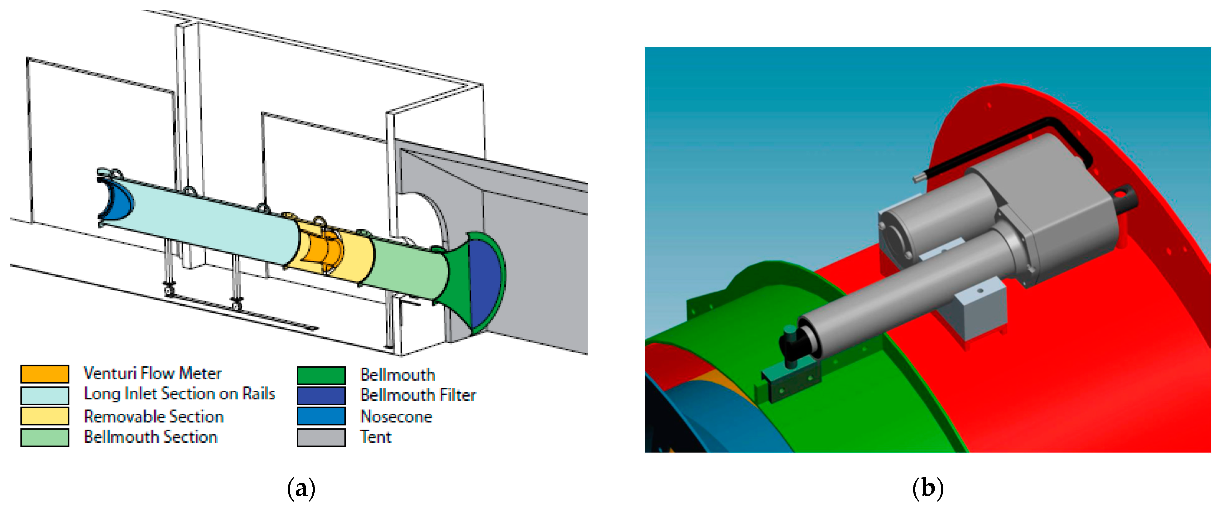
As part of the new inlet system, a large settling chamber, filter, and area-reducing bellmouth were installed just outside the test cell to draw ambient air, as shown in
Figure 9a. This inlet extension was used to ensure a more uniform incoming flow and to isolate unsteadiness effects from crosswinds and gusts. A BT-IP16 Wyatt truncated venturi flowmeter, placed in a removable duct section, was also added to allow for more accurate mass flow rate measurement at the inlet of the compressor. Downstream of the venturi, an insulated circular duct section measuring 2 feet in diameter and 10 feet long dissipated the venturi jet before it reached an elliptical nose cone. This nosecone was installed directly upstream of the compressor to contract the flow area and direct the incoming flow to meet the inner diameter of the flow path. After this contraction, the air passed through the existing 180° AIP traverse.
The change to a rear-driven facility resulted in the loss of the sliding conical throttle and exhaust to keep the exiting air from interacting with the driveline components. A new throttle was designed to back-pressure the system using an annular sliding gate throttle valve at the exit of the compressor, shown in
Figure 9b. After passing through the throttle valve, the air was exhausted from the building, returning to ambient conditions through a new scroll collector and exit ducting. Investments into an orifice plate and flowmeter provided the capability for measuring the bleed flow under the Stator 3 knife seal. The installed flowmeter relates the geometry and differential pressure to a mass flow rate, and additional instrumentation was added to the bearing plate to monitor the cavity pressure and temperature characteristics.
4.2. Baseline Performance/Boundary Condition Characterization (2010–2012)
After mechanical checkout of the facility, a steady-state performance map was established on the original casing at design speed and three off-design speeds across various loading conditions. At each loading condition, the stator vanes were traversed with new seven-element total temperature and total pressure Kiel-head rakes (2nd generation rakes) to obtain detailed pitchwise information at the trailing edge of each stator [
17]. Pressure and temperature measurements comply with ASME PTC 19.2 and ASME PTC 19.3 standards, respectively (
Figure 10).
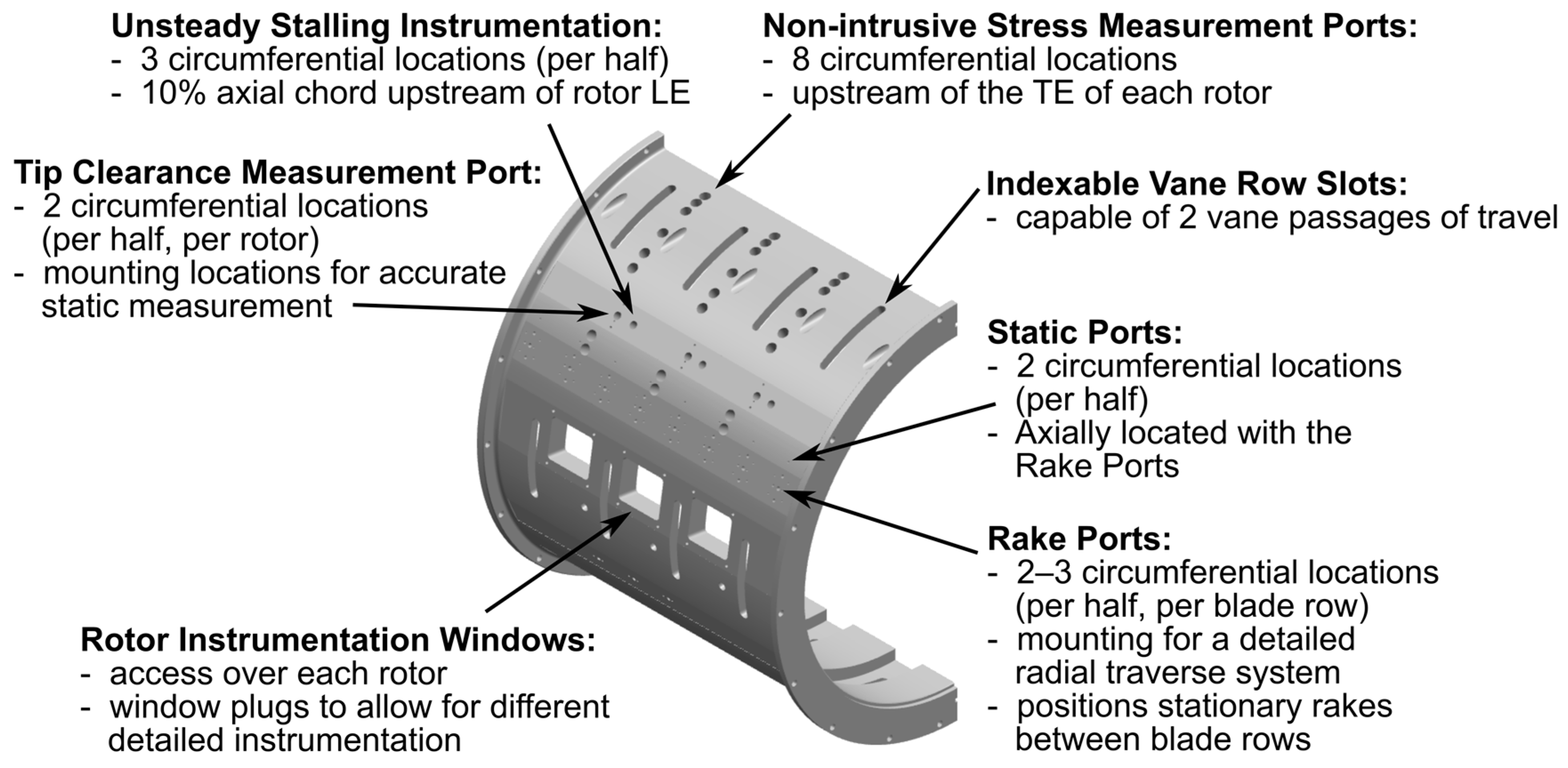
Following this initial performance characterization, a new baseline casing sponsored by Rolls-Royce was designed and manufactured, providing vast improvements in instrumentation access. Central features and capabilities of the new casing design are shown in
Figure 10. Around the same time, the effectiveness of the inlet system was studied. The bellmouth generated additional turbulence near the endwalls since a more controlled experiment was required. Renovations were completed to install an ASME PTC 19.5 standard long-form Venturi mass flowmeter, significantly improving accuracy in mass flow rate measurements of the primary flow path and providing a more uniform flow field in terms of turbulent quantities. An additional 22 feet of inlet ducting was installed [
19] to accommodate the installation requirements of the flowmeter, shown in
Figure 11. This installation moved the settling chamber, area-reducing bellmouth, and flow conditioning upstream, further isolating the inlet flow from crosswinds, gusts, and low-frequency oscillatory effects of local atmospheric conditions. A sensitivity and repeatability analysis was paired with a detailed investigation of the flow field at the compressor AIP using the existing 180° traverse system [
20,
21,
22]. These studies established a baseline inlet total pressure and total temperature profile necessary for calculating key performance metrics (efficiency, TPR, TTR, etc.) and provided accurate boundary conditions for computational efforts.
4.3. Small-Core Research Topics Funded by NASA—Casing and Instrumentation Updates (2011–2015)
Over the last decade, another well-established primary area of research in the P3S facility has included investigations of rotor tip leakage flows [
18,
23,
24]. The industry has continually trended toward a smaller engine core to reduce weight and increase propulsive efficiency, resulting in smaller, high-pressure compressor blading and larger relative tip clearances, particularly in the rear stages. Thus, further investigations working toward a better understanding of rotor tip leakage flow to improve overall gas turbine engine efficiency became important.
In 2011, NASA awarded a grant to Purdue to study the tip leakage flow structure and complex flow field in the representative rear stages of a high-pressure compressor core. The investigation produced detailed experimental data on PAX100, providing a database for comparison with results from computational models to better understand and predict the phenomena involved with various tip clearance designs, particularly in off-design performance and stage matching.
To experimentally characterize the tip leakage trajectory at different operating clearances, two brand-new, nearly identical casings to the original 1.5% baseline casing were designed and manufactured in 2012, with different tip clearance heights: 3.0% and 4.0% of overall annulus height. Compressor performance data were acquired using these three different casing configurations at four corrected speed lines across various loading conditions. In addition to the casings, the NASA funding procured seven-element total pressure and total temperature rakes (3rd generation rakes), used to measure the effects of tip leakage flows on radial profiles and wake shapes throughout the compressor. These data were also used to evaluate various tip clearance effects on compressor efficiency, stall margin, and peak pressure rise capability [
24,
25,
26,
27,
28]. All data were supplemented with dynamic rotor tip clearance measurements from a newly acquired CapaciSense 5-series frequency-modulated (FM) capacitance probe tip clearance measurement system (produced by Pentair Thermal Management, now GadCap Technical Solutions).
High-frequency-response piezoresistive pressure transducers (Kulite Semiconductor Products) installed in instrumentation blocks mounted in the over-rotor windows of the casing, shown in
Figure 12, were also funded by this research endeavor. These embedded Kulite arrays were used to quantify the unsteady endwall pressure fluctuations and trajectories of tip leakage vortices for each rotor blade row while monitoring their development across the passage [
28]. A Precision Filters 28000 signal condition system, installed with Precision 28118 full bridge amplification cards, provided signal conditioning for the transducers.
Thermal anemometry measurements were also acquired to evaluate the unsteady three-dimensional velocity components observed throughout the compressor. A Dantec StreamLine Pro frame featuring a 91C10 constant-temperature anemometer (CTA) bridge provided the signal conditioning for the thermal anemometry measurements. This Dantec system was also applied to investigate the boundary layer development on each stator by developing surface-mounted hot-film anemometry in the facility to derive quasi-shear stress measurements [
29,
30,
31,
32,
33,
34].
A powder-paint flow visualization technique was developed and performed in the facility [
30,
31,
32,
33,
34] to help understand the loss development in the compressor by highlighting secondary flows such as stator corner separations and endwall flow patterns at different loading conditions, clocking configurations, and tip clearances. Vane clocking effects on compressor performance were quantified for nine loading conditions and six clocking configurations, and it was shown that vane clocking effects were small at low loading and near stall conditions but were strong with high loading conditions. Additionally, stator wake profile comparison and flow visualization revealed that total pressure loss changes across the stator were due to a corner separation caused by the interaction between the S1 wake and R2 tip leakage flow. Different clocking configurations heavily influenced this region of corner separation relative unsteadiness and blockage.
Fundamental work on an additively manufactured two-vane passage S2 section provided the foundation for continued research efforts into additive manufacturing of research compressor components [
35]. The section was manufactured using the direct metal laser sintering (DMLS) technique with Stainless Steel PH1. The stator insert featured a vane with leading-edge Kiel heads and corresponding pressure tubulation incorporated directly into the vane for total pressure measurements. Additional static pressure taps and tubulation were integrated into the hub shroud. While the purpose of the S2 section was for proof of concept and experimentation with additive manufacturing, it allowed for measurements to be taken over the knife seals—a challenging area of investigation within the facility and provided avenues for new research. Additional funding from NASA allowed for the modification of S1 and S2 to incorporate high-frequency pressure transducers to provide a method of further investigating the unsteady flow in the shrouded stator cavity region. Computational models were also used to investigate these cavity regions in greater detail [
19,
36]. The stator hub instrumentation is shown in
Figure 13.
Finally, to investigate the three-dimensional flow field non-intrusively on the embedded stage of the PAX100 compressor, PIV was performed in the facility, as shown in
Figure 14, and quartz casing windows were manufactured to gain optical access through the casing. PIV measurements were taken to highlight the tip leakage flow trajectories and compared to the results obtained from the over-rotor, unsteady pressure measurements [
37].
4.4. Aeromechanics Research with the GUIde IV Consortium: New Instrumentation Development (2012–2013)
Another opportunity for instrumentation advancement came from work with the GUIde IV Consortium—an interdisciplinary research consortium composed of industry sponsors, government agencies, and universities to study turbomachinery aeromechanics. Aspects of the unique PAX100 machine—engine-representative speeds and similarity, repeating upstream vane counts, and a reduction of three blades per row for successive rotor blade row counts—provided ideal boundary conditions for the detailed study of forcing functions and forced response of the embedded stage at/near rotor resonant conditions. Funding from the consortium enabled the acquisition of detailed forcing function and response data of the embedded stage to provide an opportunity to calibrate and develop CFD tools for rotor forced-response predictions. This research investigation included measuring the unsteady aerodynamic forcing function using detailed flow field traverses and measuring the rotor response using the NSMS tip timing system from when PAX100 was a front-driven facility.
The embedded rotor stage of the PAX100 compressor was evaluated at the resonant crossing of the 1T vibratory mode using a variety of measurements to create a baseline aerodynamic and aeromechanical dataset. In addition to steady-state compressor performance measurements, NSMS tip-timing, steady pressure probes, high-frequency pressure transducers (embedded in the casing over a downstream rotor and in probes), and cross-film thermal anemometry were all used to characterize the forcing function at these resonant crossings [
38,
39,
40].
An additional segmented stator ring, shown in
Figure 15, was developed for S2 accommodating a 2-passage vane section embedded with high-frequency pressure transducers on the pressure and suction surfaces to measure the unsteady surface pressure on S2 [
32,
38,
41,
42]. This instrumentation focused on capturing the total pressure loss and boundary layer transition resulting from blade row interactions involved with resonant conditions and vane row clocking.
4.5. Humidity Effects and Research Collaborations (2013–2014)
In these initial research projects on the rear-driven facility, it was recognized after performing several data acquisition campaigns and carefully analyzing their results that the compressor performance would change slightly depending on the time of the year that tests were being performed—despite familiar corrections based on ambient temperature and pressure. The ability to ensure repeatability in measurements and record small changes in performance parameters is crucial for experimental research. Incoming, unconditioned ambient air in the Midwest United States is subject to significant fluctuations in humidity over the course of the year. Accounting for these fluctuations proved essential in reconciling measurements taken throughout the year and ensuring performance data was represented correctly during experimental testing. Solely using perfect gas assumptions, error calculations indicated at least a 0.5% deviation in corrected speed on the PAX100 compressor, exceeding the measurement uncertainty range and may misrepresent compressor performance [
43,
44]. Thus, a new approach was introduced by modeling humid air as a real gas and adjusting for changes in sound speed with real-time rotational speed adjustments. This approach provided the first open literature publication experimentally comparing the traditional method of correcting rotational speed based on inlet temperature with a more accurate method that accounts for changes in the speed of sound in humid air. Most importantly, the method collapsed the slight differences in the data, achieving a new level of repeatability across different inlet conditions and enabling long-term studies with unprecedented reliability.
With three different tip-clearance casings and the procurement of the fast-response instrumentation with NASA funding, the effects of rotor tip clearance height and tip-leakage flows on compressor stability were investigated. Ports for high-frequency response Kulite pressure transducers were incorporated into all three new casing designs and located circumferentially slightly upstream of each rotor row to investigate stall inception at different tip clearances. While studies considering tip clearance effects on stability had been primarily limited to low-speed compressors and single-stage machines, these investigations filled a crucial void using an engine-representative, multistage compressor design like PAX100, supplementing the University of Cambridge’s Whittle Laboratory stall inception studies through collaboration [
45].
4.6. GUIde V Consortium: New PAX100 Configurations and Instrumentation (2014–2016)
With the success of the research investigations performed during GUIde IV, further funding came with the next phase of aeromechanics research, known as GUIde V. An extension of GUIde IV, the research topics focused on higher-order modes, isolating the S1 forcing functions from the S2 forcing function and examining inlet distortion effects on the PAX100 compressor.
Much of the instrumentation developed during GUIde IV was used to characterize the higher-order mode response and mode shapes on the embedded stage [
46,
47]. However, new S1 halves were designed to experimentally investigate the implementation of reduced vane count and non-uniform vane spacing (NUVS) to compare and examine the resulting forced response conditions on the R2 1T and 1CWB vibratory modes [
48]. Two additional S1 rings were designed and manufactured: one with a reduced vane count and one with an asymmetric vane count (two halves of different vane counts). With these two additional stator vane configurations, R2 blade vibration amplitudes could be measured again in the same manner, and any differences could be attributed to this change in geometry. An aeroelastic CFD solver was also used to capture the effect of stator asymmetry on select resonant vibrational amplitudes [
49]. These results provided an understanding of the complexities associated with forced response in a multistage compressor and a detailed data set for validating computational prediction tools. Furthermore, these additional stator halves have greatly expanded the number of configurations available to the PAX100 compressor design collection.
Finally, as a further extension of aeromechanics research, a 360° circumferential traverse was designed and manufactured to investigate the influence of inlet distortion on PAX100. This investigation sought to validate and characterize the propagation and attenuation of inlet distortion effects across each stage [
50]. A low-porosity, 120° wedge-shaped screen with a honeycomb support structure was installed in the traverse mechanism upstream of the compressor, shown in
Figure 16, and rotated around the annulus. Stationary instrumentation located at the AIP and each blade row were used to capture the total pressure flow field and turbulence intensity at a high resolution around the annulus.
5. More Power, More Challenges, More Upgrades (2016–Present)
After a demonstrated capability of measuring detailed flow features repeatably, Rolls-Royce sponsored the design and fabrication of new blading compatible with the same casings, which could be easily swapped in and out with the previous hardware to facilitate technology development for their future small-core engines. As a result, an updated Rolls-Royce compressor design, PAX200, was installed in the facility, along with the necessary facility upgrades to accommodate its operation [
46].
The PAX200 compressor design featured more sophisticated blade geometry, representing modern three-dimensional design methods used with axial compressor cores. A hub-shrouded stator baseline model consisted of three new stator vane rows, three new rotor blade rows, and a variable IGV. A technology build was simultaneously designed and manufactured as the baseline model to test new concepts to improve engine efficiency. The technology builds feature additional blade rows interchangeable with components of the baseline model, including proprietary geometry features for mitigating loss associated with rotor tip leakage flow and improving stage stator diffusion and pressure recovery. The baseline blisk spacers incorporate knife-edge seals for shrouded stators and alternate spacer designs, allowing cantilevered stators to replace the shrouded stators. With the anticipation of many compressor configurations and designs, it was imperative to characterize the baseline model first for comparison with all future iterations. The different configurations are shown superimposed in
Figure 17.
In addition to the geometric blade changes, many facility design considerations were implemented in anticipation of the new PAX200 compressor. An ascending hub line replaced the previously constant annulus flow path of the PAX100 compressor with a converging annulus. The fixed outer diameter allowed the previous investments in the three split-half casings of the compressor to be incorporated. Additionally, some of the other existing facility elements were reused, with one of the main features of the redesign incorporating adaptability between future and past compressor designs, including the motor, inlet ducting, and exhaust ducting. However, many additional elements of the current facility required upgrades to accommodate the new compressor requirements of higher temperature, pressure, torque, and power. A new speed-increasing Cotta gearbox with a ratio of 4.586:1 was installed to accommodate the higher torque requirements of the new compressor design. In addition, the gearbox oil heat exchanger was moved to a dedicated structure outside the test cell to handle greater heat generation from the compressor and motor. The new gearbox required adaptations to the gearbox and motor bases to achieve the correct driveline height, and the overall driveline length was shortened to address rotordynamics concerns.
With the shorter driveline and higher torque requirements, a completely new drivetrain was installed in the facility, including a new support structure, flexible disc couplings, and an ET2350 Torquemeter from Torquemeters LTD. Measurements of torque (and power) comply with the ASME PTC 19.8 standard. Previously, isentropic efficiency had been primarily calculated and reported using the enthalpy rise (total temperature increase), although the torque-derived isentropic efficiencies were also calculated from the Lebow 1805-5K. With the new ET2350, the torquemeter-derived isentropic efficiency became the most reliable for the relatively low-temperature rise of the compressors in the facility; however, these efficiency calculations generally align with the enthalpy-rise efficiency calculations, particularly near the design point. The thermal soak in the metal surfaces of the compressors, even with the relatively low temperature rise, influences the measurements input into the enthalpy-rise isentropic efficiency formulation at the near-stall and choke extremes of the speedline. Although these temperatures are monitored during experiments, and a steady state is reached before acquiring data, the effect cannot be fully mitigated. In contrast, the torque-derived isentropic efficiency depends only on the relatively stable inlet temperature and responds nearly instantaneously. The drawback of the torque-derived isentropic efficiency for a multistage machine is the inability to isolate individual stage efficiencies.
After completing all upgrades, the remaining driveline components from the PAX100 facility are the drive motor and its baseplate. Upgrades for the exhaust include substituting a single throttle actuator inside the exhaust plenum to a three-actuator system outside the exhaust plenum to prevent overheating and back-pressure control while adding throttle bypass valves and actuator overrides to provide a fail-safe bypass exhaust path for air in case of power failure (
Figure 18).
The resulting higher power and thermal loads introduced with the new compressor design prompted the most significant upgrades of the structural components of the compressor test section. The only remaining components from the original facility at Iowa State University were finally retired while undertaking a complete redesign of the support mechanisms and driveline. Florida Turbine Technologies was contracted for the redesign, and the new components are shown in
Figure 19. These upgrades were necessary to add structural support and rigidity to accommodate the increased power and torque from the compressor, ease shaft alignment, and provide a means for centerline thermal expansion. The new support system also incorporated extra instrumentation ports and necessary routing ports for additional instrumentation capabilities and the future implementation of a slip ring.
The inlet ducting was retained from the existing facility. However, adaptations were made to support thermal imbalances between outdoor and indoor temperatures and to maintain high-precision alignment during seasonal changes. Sliding constant-spring pipe supports replaced the rigid inlet ducting supports outside the facility to accommodate vertical and horizontal ground shifts caused by frost heaving beneath the supports. Inside the test cell, adjustable legs replaced the non-adjustable rigid legs on the existing inlet ducting pieces to address thermal growth in the vertical and horizontal directions. Finally, a decoupled inlet transition, achieved by a gap with a rubber seal, was implemented into the removable inlet duct section to accommodate thermal growth in the axial direction. A second filter was added to the settling chamber to provide additional filtration with the higher mass flow rate required by the new compressor design. The current version of the P3S facility, as it stands today, is shown in
Figure 20.
New seven-element stagnation pressure and temperature Kiel-head rakes (4th generation rakes) were designed and manufactured to accommodate a converging annulus, and upgrades to the pressure system were made to account for the higher pressures associated with the new design. With multiple blade rows featured in the different configurations of the new PAX200 design, an in-situ calibration method for the capacitance probes was also developed. An air-cooled bearing system was designed and implemented for the front bearing to account for the expected heat generated from thrust loading during operation. Velocity sensors replaced the existing accelerometers, and redundancy was added to bearing outer race thermocouple measurements to ensure accurate monitoring of the bearing temperatures. Finally, modifications were made to the orifice plate flowmeter to accurately measure the mass flow bleed rate under the S3 cavity.
6. Summary
The Purdue 3-Stage Axial Compressor Research Facility has continually evolved over the last few decades to accomplish research goals in compressor performance and aeromechanics. Ivor Day’s recent IGTI scholar lecture [
51] points out the importance of high-speed compressor research in understanding things like stall inception. Low-speed machines face limitations in modeling compressibility effects and blade row interactions experienced in real machines. As other university researchers seek to expand their capabilities into the high-speed regime, the authors hope the Purdue University teams’ lessons learned over the many years can be helpful. This paper, while providing some historical context for the development of the facility into what it is today, also gives some key insights into the complexity of high-speed compressor facilities that fill the mid-TRL gap between fundamental research and real-engine conditions. While the facility has been upgraded to accommodate newer, high-technology blading, all facility changes have been accomplished to ensure that the PAX100 blading—well-published in the open literature and continued to be used by the GUIde Consortium—can still be utilized in the facility. In addition, the flexibility of the facility allows the blading to be swapped out in a few days to accommodate the schedules of different research projects, ensuring different sponsors can utilize the same facility and allowing for both proprietary and government-funded, open-access projects.
Author Contributions
Conceptualization, N.J.K.III, D.R.M. and N.L.K.; investigation, N.J.K.III, D.R.M. and N.L.K.; resources, N.L.K.; data curation, N.J.K.III, D.R.M. and N.L.K.; writing—original draft preparation, N.J.K.III, D.R.M. and N.L.K.; writing—review and editing, N.J.K.III, D.R.M. and N.L.K.; supervision, N.L.K. and A.J.K.; project administration, N.L.K. and A.J.K.; funding acquisition, N.L.K. and A.J.K. All authors have read and agreed to the published version of the manuscript.
Funding
This research was funded by Rolls-Royce Corporation, GUIde Consortium, and the National Aeronautics and Space Administration (NASA) under the ROA-2010 NRA of the Subsonic Fixed Wing project, grant number NNX11AI59A.
Data Availability Statement
The PAX100 compressor is an essentially open geometry, with datasets distributed to members of the GUIde Consortium. The PAX200 compressor is a proprietary geometry wholly owned by Rolls-Royce Corporation, and as such is unavailable for distribution. Requests for access to datasets should be directed to
nkey@purdue.edu.
Acknowledgments
The authors would like to acknowledge Pratt & Whitney/UTRC, Rolls-Royce Corporation, NASA, and the GUIde Consortium for sponsoring and allowing this research to be published over the years and for the numerous investments made to expand this facility and its instrumentation to the point that it is at today. Special thanks to the many students and researchers contributing to the wealth of knowledge and success of the facility during its lifetime. In particular, the authors also wish to take this opportunity to recognize the late Lawless, a kind person, and a wonderful mentor.
Conflicts of Interest
Author Aaron J. King was employed by the company Rolls Royce Corporation. The remaining authors declare that the research was conducted in the absence of any commercial or financial relationships that could be construed as a potential conflict of interest.
References
- Christianson, M.B. Assembly of a P&W Three-Stage Axial-Flow Compressor for Use at Iowa State University; 1985. [Google Scholar]
- Thompson, K.E. The Design and Installation of a Three-Stage, Medium Speed, Axial-Flow Research Compressor Test Rig. Master’s Thesis, Department of Mechanical Engineering, Iowa State University, Ames, IA, USA, 1987. [Google Scholar]
- Rukavina, J.P. Modification of Axial-Flow Compressor Stall Margin by Variation of Stationary Blade Setting Angles. Ph.D. Thesis, Doctor of Philosophy, Department of Mechanical Engineering, Iowa State University, Ames, IA, USA, 1991; p. 6360200. [Google Scholar]
- Wellborn, S.R. Effects of Shrouded Stator Cavity Flows on Multistage Axial Compressor Aerodynamic Performance. Ph.D. Thesis, Department of Mechanical Engineering, Iowa State University, Ames, IA, USA, 1996. [Google Scholar]
- Sharp, E. Development of a Three Stage Axial Compressor Aeromechanics Research Facility. Master’s Thesis, School of Mechanical Engineering, Purdue University, West Lafayette, IN, USA, 2001. [Google Scholar]
- Fulayter, R.D. An Experimental Investigation of Resonant Response of Mistuned Fan and Compressor Rotors Utilizing NSMS. Ph.D. Thesis, School of Mechanical Engineering, Purdue University, West Lafayette, IN, USA, 2004. [Google Scholar]
- Choi, Y.S. Investigation of the Resonant Response of Mistuned Rotors. Ph.D. Thesis, School of Mechanical Engineering, Purdue University, West Lafayette, IN, USA, 2007. [Google Scholar]
- Choi, Y.S.; Key, N.; Fleeter, S. Vane Clocking Effects on the Resonant Response of an Embedded Rotor. J. Propuls. Power 2011, 27, 71–77. [Google Scholar] [CrossRef]
- Allan, D.W. Aerodynamic Performance Characterization of an Advanced Multi-Stage Axial Compressor. Master’s Thesis, School of Mechanical Engineering, Purdue University, West Lafayette, IN, USA, 2005. [Google Scholar]
- Key, N.L. Vane Clocking Effects in an Embedded Compressor Stage. Ph.D. Thesis, School of Mechanical Engineering, Purdue University, West Lafayette, IN, USA, 2007. [Google Scholar]
- Key, N.L.; Lawless, P.B.; Fleeter, S. Vane Clocking in a Three-Stage Compressor: Frequency Domain Data Analysis. J. Propuls. Power 2009, 25, 1100–1107. [Google Scholar] [CrossRef]
- Key, N.L.; Lawless, P.B.; Fleeter, S. An Experimental Study of Vane Clocking Effects on Embedded Compressor Stage Performance. J. Turbomach. 2009, 132, 011018. [Google Scholar] [CrossRef]
- Key, N.L.; Lawless, P.B.; Fleeter, S. Rotor Wake Variability in a Multistage Compressor. J. Propuls. Power 2010, 26, 344–352. [Google Scholar] [CrossRef]
- Key, N.L. Compressor Vane Clocking Effects on Embedded Rotor Performance. J. Propuls. Power 2014, 30, 246–248. [Google Scholar] [CrossRef]
- Salontay, J.R. A Computational Investigation of Vane Clocking Effects on Compressor Forced Response and Performance. Master’s Thesis, School of Mechanical Engineering, Purdue University, West Lafayette, IN, USA, 2010. [Google Scholar]
- Salontay, J.; Key, N.; Fulayter, R. A Computational Investigation of Vane Clocking Effects on Compressor Forced Response. In Proceedings of the 48th AIAA Aerospace Sciences Meeting Including the New Horizons Forum and Aerospace Exposition, Orlando, FL, USA, 4–7 January 2010. [Google Scholar]
- Talalayev, A. On the Renovation of the Three-Stage Axial Compressor Research Facility for Compressor Performance Research. Master’s Thesis, School of Mechanical Engineering, Purdue University, West Lafayette, IN, USA, 2011. [Google Scholar]
- Brossman, J.R. An Investigation of Rotor Tip Leakage Flows in the Rear-Block of a Multistage Compressor. Ph.D. Thesis, School of Mechanical Engineering, Purdue University, West Lafayette, IN, USA, 2012. [Google Scholar]
- Ball, P. An Experimental and Computational Investigation on the Effects of Stator Leakage Flow on Compressor Performance. Master’s Thesis, School of Aeronautics and Astronautics, Purdue University, West Lafayette, IN, USA, 2013. [Google Scholar]
- Brossman, J.; Smith, N.; Talalayev, A.; Key, N. The Development of a Multistage Axial Compressor Research Facility. In Proceedings of the 47th AIAA/ASME/SAE/ASEE Joint Propulsion Conference & Exhibit, San Diego, CA, USA, 31 July–3 August 2011. [Google Scholar]
- Brossman, J.R.; Smith, N.R.; Talalayev, A.; Key, N.L. Tailoring Inlet Flow to Enable High Accuracy Compressor Performance Measurements. Int. J. Turbo Jet Engines 2011, 28, 309–320. [Google Scholar] [CrossRef]
- Brossman, J.; Ball, P.; Smith, N.; Methel, J.; Key, N. The Sensitivity of Multistage Compressor Performance to Inlet Boundary Conditions. In Proceedings of the 48th AIAA/ASME/SAE/ASEE Joint Propulsion Conference & Exhibit, Atlanta, GA, USA, 30 July–1 August 2012; American Institute of Aeronautics and Astronautics: Atlanta, GA, USA, 2012. [Google Scholar]
- Berdanier, R.A. An Experimental Characterization of Tip Leakage Flows and Corresponding Effects on Multistage Compressor Performance. Ph.D. Thesis, School of Mechanical Engineering, Purdue University, West Lafayette, IN, USA, 2015. [Google Scholar]
- Berdanier, R.A.; Key, N.L. An Experimental Investigation of the Flow Physics Associated With End Wall Losses and Large Rotor Tip Clearances as Found in the Rear Stages of a High Pressure Compressor; National Aeronautics and Space Administration, Glenn Research Center: Cleveland, OH, USA, 2015. [Google Scholar]
- Berdanier, R.A.; Key, N.L. Experimental Investigation of Factors Influencing Operating Rotor Tip Clearance in Multistage Compressors. Int. J. Rotating Mach. 2015, 2015, e146272. [Google Scholar] [CrossRef]
- Berdanier, R.A.; Key, N.L. The Effects of Tip Leakage Flow on the Performance of Multistage Compressors Used in Small Core Engine Applications. J. Eng. Gas Turbines Power 2015, 138, 052605. [Google Scholar] [CrossRef]
- Berdanier, R.A.; Key, N.L. A Novel Data Reduction Technique for Single Slanted Hot-Wire Measurements Used to Study Incompressible Compressor Tip Leakage Flows. Exp. Fluids 2016, 57, 29. [Google Scholar] [CrossRef]
- Berdanier, R.A.; Key, N.L. Experimental Characterization of Tip Leakage Flow Trajectories in a Multistage Compressor. J. Propuls. Power 2016, 32, 1022–1032. [Google Scholar] [CrossRef]
- Smith, N.R.; Key, N.L. Unsteady Vane Boundary Layer Response to Rotor–Rotor Interactions in a Multistage Compressor. J. Propuls. Power 2014, 30, 416–425. [Google Scholar] [CrossRef]
- Smith, N.R. An Experimental Study on the Effects of Blade Row Interactions on Aerodynamic Loss Mechanisms in a Multistage Compressor. Ph.D. Thesis, School of Aeronautics and Astronautics, Purdue University, West Lafayette, IN, USA, 2015. [Google Scholar]
- Smith, N.R.; Key, N.L. Vane Clocking Effects on Stator Suction Side Boundary Layers in a Multistage Compressor. Int. J. Rotating Mach. 2016, 2016, 5921463. [Google Scholar] [CrossRef]
- Smith, N.R.; Key, N.L. A Comprehensive Investigation of Blade Row Interaction Effects on Stator Loss Utilizing Vane Clocking. J. Turbomach. 2018, 140, 071004. [Google Scholar] [CrossRef]
- Smith, N.R.; Key, N.L. Vane Clocking Effects on Stator Loss for Different Compressor Loading Conditions. J. Propuls. Power 2015, 31, 519–526. [Google Scholar] [CrossRef]
- Smith, N.R.; Key, N.L. Flow Visualization for Investigating Stator Losses in a Multistage Axial Compressor. Exp. Fluids 2015, 56, 94. [Google Scholar] [CrossRef]
- Berdanier, R.A.; Key, N.L. Toward Understanding Tip Leakage Flows in Small Compressor Cores Including Stator Leakage Flow; National Aeronautics and Space Administration, Glenn Research Center: Cleveland, OH, USA, 2017. [Google Scholar]
- Kamdar, N. Computational Investigation of Cavity Leakage Flow and Windage Within an Axial Compressor Stator Well. Master’s Thesis, School of Mechanical Engineering, Purdue University, West Lafayette, IN, USA, 2018. [Google Scholar]
- Bhattacharya, S.; Berdanier, R.A.; Vlachos, P.P.; Key, N.L. A New Particle Image Velocimetry Technique for Turbomachinery Applications. J. Turbomach. 2016, 138, 124501. [Google Scholar] [CrossRef]
- Murray, W.L., III. Experimental Investigation of a Forced Response Condition in a Multistage Compressor. Master’s Thesis, School of Aeronautics and Astronautics, Purdue University, West Lafayette, IN, USA, 2014. [Google Scholar]
- Murray III, W.L.; Key, N.L. Experimental Investigation of a Forced-Response Condition in a Multistage Compressor. J. Propuls. Power 2015, 31, 1320–1329. [Google Scholar] [CrossRef]
- Murray III, W.L.; Key, N.L. Detection of Rotor Forced Response Vibrations Using Stationary Pressure Transducers in a Multistage Axial Compressor. Int. J. Rotating Mach. 2015, 2015, 198534. [Google Scholar] [CrossRef]
- Smith, N.R.; Murray III, W.L.; Key, N.L. Considerations for Measuring Compressor Aerodynamic Excitations Including Rotor Wakes and Tip Leakage Flows. J. Turbomach. 2015, 138, 031008. [Google Scholar] [CrossRef]
- Smith, N.R.; Key, N.L. Blade-Row Interaction Effects on Unsteady Stator Loading in an Embedded Compressor Stage. J. Propuls. Power 2017, 33, 248–255. [Google Scholar] [CrossRef]
- Smith, N.R.; Berdanier, R.A.; Fabian, J.C.; Key, N.L. Reconciling Compressor Performance Differences for Varying Ambient Inlet Conditions. J. Eng. Gas Turbines Power 2015, 137, 122603. [Google Scholar] [CrossRef]
- Berdanier, R.A.; Smith, N.R.; Fabian, J.C.; Key, N.L. Humidity Effects on Experimental Compressor Performance—Corrected Conditions for Real Gases. J. Turbomach. 2014, 137, 031011. [Google Scholar] [CrossRef]
- Berdanier, R.A.; Smith, N.R.; Young, A.M.; Key, N.L. Effects of Tip Clearance on Stall Inception in a Multistage Compressor. J. Propuls. Power 2017, 34, 308–317. [Google Scholar] [CrossRef]
- Kormanik, N.J., III. Characterization of Aerodynamic Forcing Functions for Embedded Rotor Resonant Response in a Multistage Compressor. Master’s Thesis, School of Aeronautics and Astronautics, Purdue University, West Lafayette, IN, USA, 2017. [Google Scholar]
- Matthews, D.R. Unsteady Aerodynamics and Blade-Row Interactions in the Embedded Stage of an Axial Compressor. Master’s Thesis, School of Aeronautics and Astronautics, Purdue University, West Lafayette, IN, USA, 2017. [Google Scholar]
- Aye-Addo, P.A.N. An Experimental Study of the Effects of Vane Count and Non-Uniform Vane Spacing on Rotor Resonant Response. Master’s Thesis, School of Aeronautics and Astronautics, Purdue University, West Lafayette, IN, USA, 2016. [Google Scholar]
- Monk, D.J.W. A Computational Analysis of the Aerodynamic and Aeromechanical Behavior of the Purdue Multistage Compressor. Master’s Thesis, School of Mechanical Engineering, Purdue University, West Lafayette, IN, USA, 2014. [Google Scholar]
- Rusu, R. Experimental Investigation of Inlet Distortion in a Multistage Axial Compressor. Master’s Thesis, School of Aeronautics and Astronautics, Purdue University, West Lafayette, IN, USA, 2017. [Google Scholar]
- Day, I.J. Stall, Surge, and 75 Years of Research. J. Turbomach. 2015, 138, 011001. [Google Scholar] [CrossRef]
| Disclaimer/Publisher’s Note: The statements, opinions and data contained in all publications are solely those of the individual author(s) and contributor(s) and not of MDPI and/or the editor(s). MDPI and/or the editor(s) disclaim responsibility for any injury to people or property resulting from any ideas, methods, instructions or products referred to in the content. |
© 2024 by the authors. Licensee MDPI, Basel, Switzerland. This article is an open access article distributed under the terms and conditions of the Creative Commons Attribution (CC BY) license (https://creativecommons.org/licenses/by/4.0/).


