Article

Ontological Airspace-Situation Awareness for Decision System Support

by
Carlos C. Insaurralde
1,* and
Erik Blasch
2
1
Bristol Robotics Laboratory, University of the West of England, Bristol BS16 1QY, UK
2
MOVEJ Analytics, Fairborn, OH 45324, USA
*
Author to whom correspondence should be addressed.
Aerospace 2024, 11(11), 942; https://doi.org/10.3390/aerospace11110942
Submission received: 8 July 2024 / Revised: 7 November 2024 / Accepted: 11 November 2024 / Published: 15 November 2024
(This article belongs to the Collection Avionic Systems)

Abstract

:
Air Traffic Management (ATM) has become complicated mainly due to the increase and variety of input information from Communication, Navigation, and Surveillance (CNS) systems as well as the proliferation of Unmanned Aerial Vehicles (UAVs) requiring Unmanned Aerial System Traffic Management (UTM). In response to the UTM challenge, a decision support system (DSS) has been developed to help ATM personnel and aircraft pilots cope with their heavy workloads and challenging airspace situations. The DSS provides airspace situational awareness (ASA) driven by knowledge representation and reasoning from an Avionics Analytics Ontology (AAO), which is an Artificial Intelligence (AI) database that augments humans’ mental processes by means of implementing AI cognition. Ontologies for avionics have also been of interest to the Federal Aviation Administration (FAA) Next Generation Air Transportation System (NextGen) and the Single European Sky ATM Research (SESAR) project, but they have yet to be received by practitioners and industry. This paper presents a decision-making computer tool to support ATM personnel and aviators in deciding on airspace situations. It details the AAO and the analytical AI foundations that support such an ontology. An application example and experimental test results from a UAV AAO (U-AAO) framework prototype are also presented. The AAO-based DSS can provide ASA from outdoor park-testing trials based on downscaled application scenarios that replicate takeoffs where drones play the role of different aircraft, i.e., where a drone represents an airplane that takes off and other drones represent AUVs flying around during the airplane’s takeoff. The resulting ASA is the output of an AI cognitive process, the inputs of which are the aircraft localization based on Automatic Dependent Surveillance–Broadcast (ADS-B) and the classification of airplanes and UAVs (both represented by drones), the proximity between aircraft, and the knowledge of potential hazards from airspace situations involving the aircraft. The ASA outcomes are shown to augment the human ability to make decisions.

1. Introduction

The increasingly growing and varying input information from Communication, Navigation, and Surveillance (CNS) systems [1] along with the proliferation of Unmanned Aerial Vehicles (UAVs) has complicated Air Traffic Management (ATM) operations. The proliferation of the use of drones, aerial robots, and other UAVs has been of great concern for aviation authorities because of safety and security (including cybersecurity). One of the ways to deal with such complexity is by means of a decision support system (DSS) in the form of a software application that has been proposed to help ATM personnel and aircraft pilots cope with their heavy workloads and challenging airspace situations. The fundamental goal is to support air traffic controllers (ATCs) and aviators to make decisions rather than replace them with a DSS. Advancements in DSS technologies are also suitable for Unmanned Aerial System Traffic Management (UTM), promoting an increase in the level of autonomy to assist decisional processes (currently carried out by humans).
An essential component of the DSS is an Avionics Analytics Ontology (AAO) [2] that is the driver for airspace situational awareness (ASA). The AAO is an Artificial Intelligence (AI) database that allows humans to augment their mental processes by means of implementing AI cognition and provides knowledge representation and reasoning (level 1 AI [3]). Ontologies for avionics have also been of interest to the Federal Aviation Administration (FAA) Next Generation Air Transportation System (NextGen) and the Single European Sky ATM Research (SESAR) project [4]. NASA has also been developing an ontology to support aviation. While each agency has shown interest in developing an ontology, a unified approach has yet to be standardized and adopted by the industry, potentially because these ontologies do not deal with airspace situational awareness (ASA) and ultimately human–machine decision-making processes.
This paper presents an AAO computer tool for decision-making support (DSS) in ATM/UTM. Relevant stakeholders such as ATCs and aircraft pilots can make use of the AAO approach to decide on airspace situations. The DSS software application includes an AAO knowledge engine for the ASA process, which has its foundation in AI cognition. The performance of the DSS is demonstrated by means of an application example and experimental test results from a UAV AAO (U-AAO) framework prototype. The AAO-based DSS is demonstrated from park-testing trials emulating downscaled application scenarios that replicate takeoffs where drones play the role of different aircraft in an airspace situation. Thus, conventional small drones play the role of airplanes that take off and land, while drones are AUVs flying around during the airplane’s operation. The ASA provided by the DSS is an AI cognitive process based on inputs from aircraft localization provided by Automatic Dependent Surveillance–Broadcast (ADS-B) devices. The DSS seeks to augment the cognitive abilities of ATCs to make ASA decisions.
The paper is organized as follows. Section 2 discusses related existing technologies and applications. Section 3 presents fundamental principles relevant to the development of cognitive SAW based on ontologies (concepts and their relations). Section 4 presents the details of the framework prototype and application scenarios used for the experiments, the results of which are shown in this paper. Section 5 presents experimental results obtained from the use of the ontological SAW approach (included in the AAO) and the DSS. Section 6 discusses lessons learned from the experiments. Finally, Section 7 provides concluding remarks and the next research steps.

2. Related Works

The use of ontologies in different domains (e.g., medicine, biological sciences, business, etc.) has grown since the advent of the Web Ontology Language (OWL) and has attracted the attention of the aviation community. The main applications of aviation ontology are for ATM and UTM, including aircraft operations and collision avoidance in airspace situations. Mid-air collisions (MACs) are a key risk in airspaces [2]. There are several regulations, case studies [5], reports, and tools (e.g., International Civil Aviation Organization (ICAO) Collision Risk Methodology [6]) to deal with collision risks [7]. Collisions between manned aircraft and UAVs [8,9,10] are of particular interest for the research presented in this paper. The AAO idea is to document elements and characteristics of the airspace in the form of “knowledge” rather than merely information or even data, with the potential to carry out actions based on different ATM/UTM situations.
Aviation regulatory bodies such as the Federal Aviation Administration (FAA) Next Generation Air Transportation System (NextGen) and Eurocontrol by means of the Single European Sky ATM Research (SESAR) [3] initiative have considered the use of ontologies for future airspace systems such as the ATM Information Reference Model (AIRM) ontology [11]. NASA, on the other hand, has proposed the ATM Ontology (ATMOnto) [12] to handle the knowledge of air traffic operations. While Eurocontrol and NASA propose ontological models with a similar purpose, they differ in design due to different regulations from Europe and the USA [13].
Apart from the initiatives from the FAA, Eurocontrol, and NASA, there are some proposals to use ontologies from researchers and practitioners from academia to support ATM/UTM systems [14,15]. Some of these approaches are ontologies to deal with conflicts and collisions of AUVs to support a Collision Avoidance System (CAS) [16,17], the detection of anomalies from ATM system-based ontologies to detect fake ADS-B messages [18], and an ontology for flight safety messages from ATM in order to facilitate the management of a large volume of data and the correct interpretation of them [19]. Other initiatives look at autonomy aspects to be considered in commercial aviation to provide a framework for AUVs that can operate safely in public scenarios [20] and for teaming and collaboration of AUVs [21].
Additionally, there are some proposals to use ontologies to support other areas of the aviation sector. Some of these projects include the use of an ontology to improve customer service in civil aviation [22]. The use of ontologies is also an attractive solution for a description language for aviation scenarios [23]. A language implementation is a discovery mechanism to notate knowledge on avionics maintenance using unsupervised concept learning [24], and more generally, the use of ontologies for aircraft maintenance [25,26] and heterogeneous maintenance records [27]. A project that integrates general aviation data by means of ontologies was developed for the Information Catalyst for Aviation Services (ICARUS) [28]. Also, ontologies have been proposed for the integration of models from the conceptual design of aircraft [29] for eventual manufacturing [30] as well as the prognostic and health management of aircraft [31].
There is a proposal to investigate air crashes by means of the use of ontologies [32] and the fusion of aircraft equipment fault information [33]. Likewise, ontologies for the support of flight desk avionics in aircraft cockpits [34], reconfiguration for Integrated Modular Avionics (IMA) systems [35], resource modeling and a matching framework for avionics systems [36], and an engineering framework for the rapid generation of air vehicle configurations [37]. On the other hand, OntoCommos is a European initiative to use ontology-based demonstrators to support operations of the industrial sector, with which the aerospace industry is involved, with a goal to improve interoperability and data standardization during the design stage [38]. The use of ontologies as part of AI in aviation, including ATM, is also considered by the European Aviation Artificial Intelligence High Level Group and is reported in their FLY AI Report [39].
However, while there are a few cases reported of the use of ontologies in aviation, none of these specifically use ontologies for the artificial cognition required by SAW to support decision-making in ATM, including UAV cyber protection among a swarm of drones. In addition, the AAO-based approach presented in this paper paves the way to exploit key benefits of ontologies as a good technology to amalgam connections between other relevant avionics systems related to flight performance and collision avoidance. For instance, in the Aviation Performance Measuring System (APMS) [40] and the Traffic Collision Avoidance System (TCAS), the outputs from these systems can feed the AAO in an effort to combine information for even more realistic SAW of airspace scenarios.

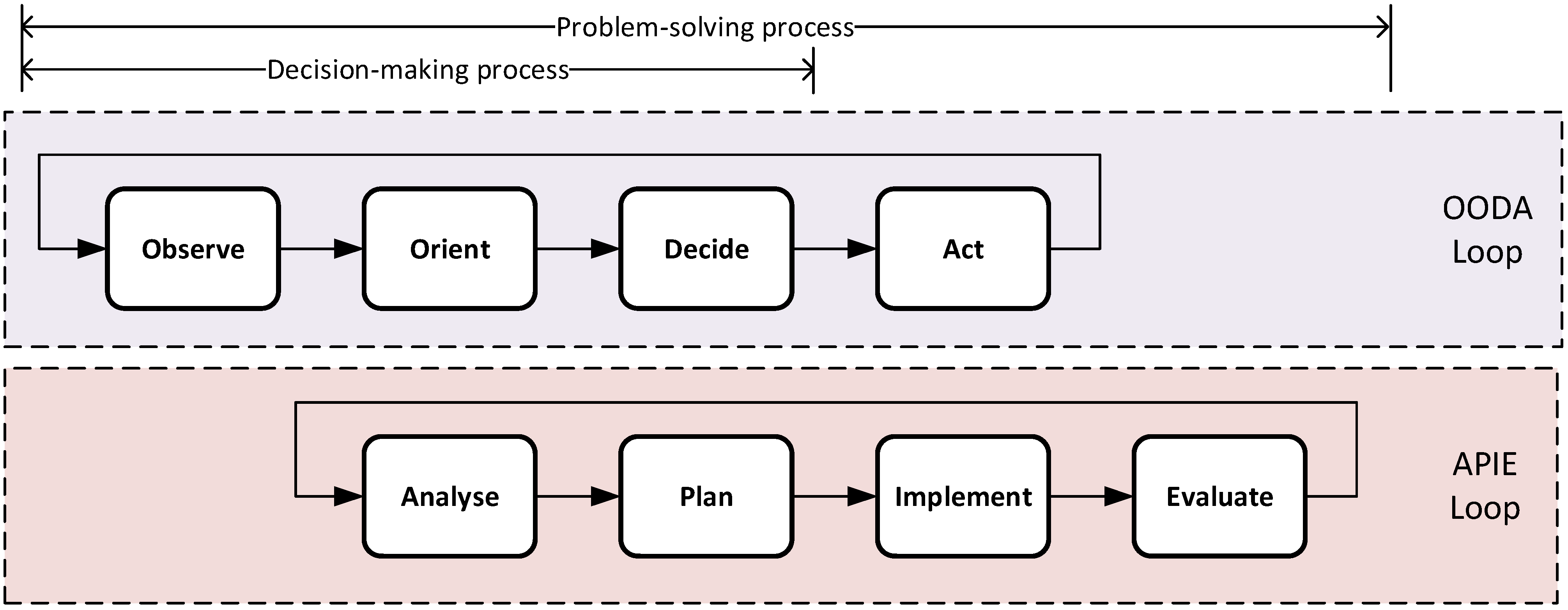
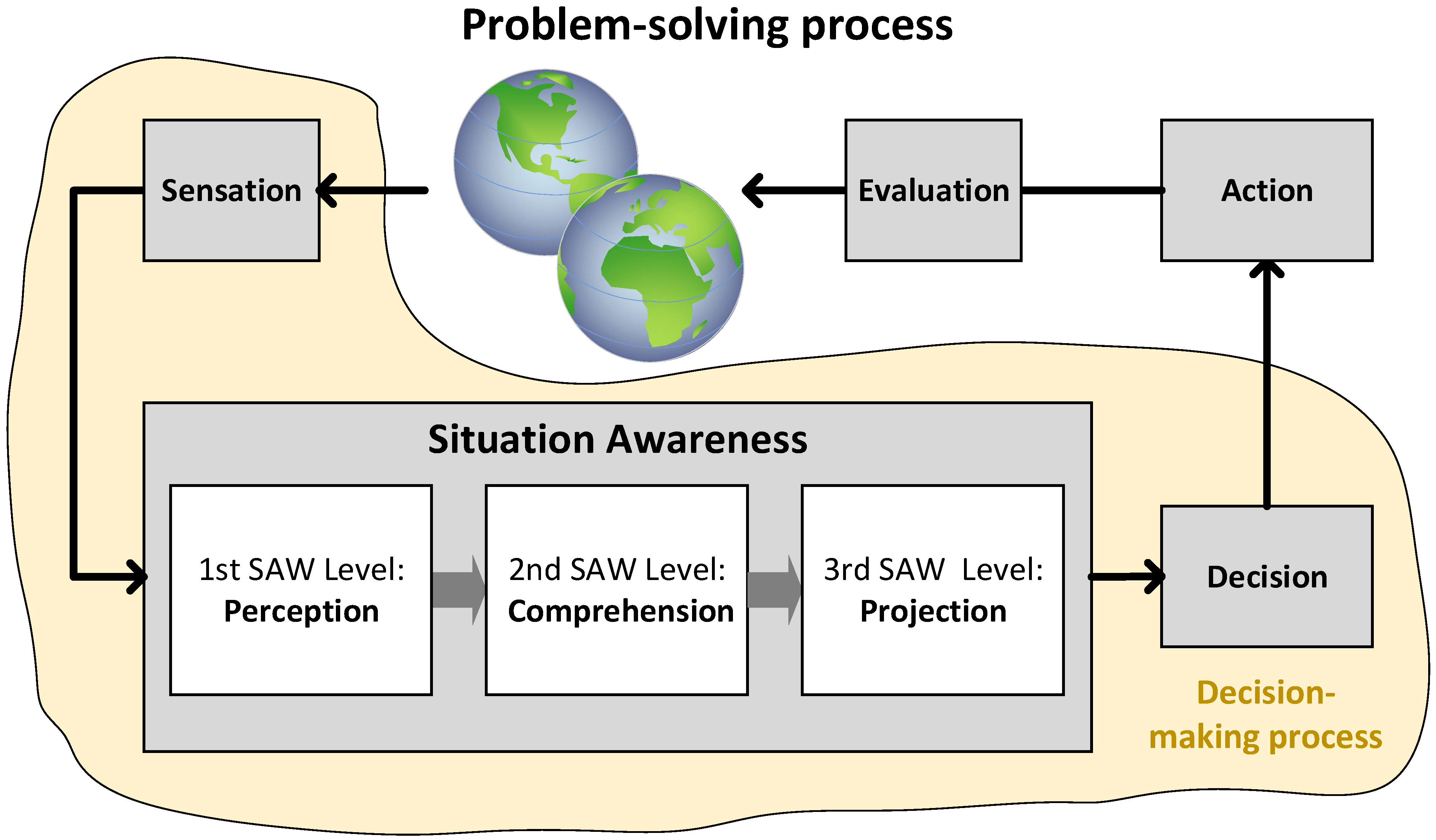
3. Knowledge-Based Situation Awareness

This section presents the foundations of the SAW process based on AI cognition provided by the AAO as the main component to ultimately support decision-making for Air Traffic Management (ATM) situations.

3.1. Air Traffic Situation Awareness

Pilots and air traffic controllers (ATCs) are required to be fully aware of airspace situations to make timely decisions for ATM by utilizing decision support systems (DSSs). DSS performance is essential for the highly sophisticated cognitive tasks they must carry out to realize a potentially hazardous situation and plan further actions to sort out any circumstantial problems. Therefore, the DSS is meant to provide situation awareness (SAW). SAW is the ability to be aware of and understand what is happening in the surroundings, both at the present time and in the future, through prediction. A SAW capability allows human and machine teaming systems to understand dynamic and complex environments and operate with them.
ATCs and pilots exercise mental faculties by performing intelligent tasks to solve airspace situations. Problem-solving is a well-known term and used in AI, which frames the cognitive approach for the DSS as an AI solution. The SAW problem-solving model in Figure 1 organizes the cognitive modeling process for either natural (animal/human) or artificial (machine) cognition. Figure 1 shows a sequential model for problem-solving processes, which is a combination of two models: The Observe–Orient–Decide–Act (OODA) model [41], and the Assess, Plan, Implement, and Evaluate (APIE) model [42]. The OODA model is one of the most popular approaches for decision-making processes in the human factors research community. Likewise, the OODA model was derived based on how pilots decide on what to do to solve problems in an airspace situation. The APIE model is one of the most popular approaches for nursing practice processes in the healthcare arena.
The problem-solving process consists of two main processes: (1) a decision-assessment process (observe, orient) and (2) an action-taking process (decision, action). The former partially entails the OODA loop as it can deal with the above three first capabilities, i.e., “Observe”, “Orient”, and “Decide”, which correspond to the decision-making process, and “Act” corresponds to the enforcement process. The “Evaluate” capability is not considered by the OODA. Thus, the problem-solving process is a decision-making process plus “Act” plus “Evaluate”, i.e., OODA plus “Evaluate” (OODAE). The APIE model considers the evaluation process. For aviation methods, an extension of the OODA includes the cognitive OODA (C-OODA) that includes the evaluation methods in decision-making was applied for pilot decision-making phases [43].
ATM stakeholders in the OODAE problem-solving process observe the airspace situation, orient, decide on what to do for the given situation, act, and evaluate the evolution of the actions taken to check the effectiveness of the action-based solution. The SAW model (widely accepted in the human factors community [43]) is shown in Figure 2. It makes the two first stages (observation and orientation) of the OODAE for a decision to be taken in a typical decision-making process. The DSS makes the decision based on the SAW process. The implementation of the actions and the evaluation of their effectiveness are carried out by the airspace stakeholders (e.g., ATCs and pilots), and the humans-in-the-loop to close the problem-solving process.

3.2. Description Logic

Description Logic (DL) [45] is one way to formally represent knowledge by means of mathematical models. It allows for the definition, specification, and description of data structures and networks that become information elements to ultimately represent knowledge. DL ranges from elemental concepts to more complex concept relations.
Human decision-making in ATM requires intellectual and cognitive capabilities for perception and comprehension of situations and projection of impact and possible consequences of the given situation (e.g., an airspace situation). These general categorizations of mental functions (i.e., perception, comprehension, and projection) required by SAW in a situational decision-making process can be realized by means of DL expressions (mathematical knowledge representation). Using these expressions, a semantic reasoner can infer and surmise conclusions in airspace situations.
Perception: The SAW Perception Block is fed by “sensation” that in turn is fed by data coming from sensors such as Primary Surveillance Radars (PSRs), Secondary Surveillance Radars (SSRs), and ADS-B and sometimes other sensors, such as those producing data signals based on Electro-optical/Infrared (EO/IR) technologies. This paper shows application examples based on SAW for which ADS-B is only used. The DL equations for the perception of the airplanes and quadcopters are in Appendix A.
The perception from the SAW process is provided by the above inference-based computing tasks carried out by the reasoner.
Comprehension: The SAW Comprehension Block is fed by the SAW Perception Block. Perceived objects at the perception SAW level are comprehended in a context defined by the airspace situation. The detection of UAVs in the SAW Perception Block is not enough to conclude whether the unmanned aircraft are a hazard for other aircraft and, in particular, airplanes and helicopters authorized to use the airspace. Thus, the SAW comprehension level helps us to understand the situation context by using internal inputs and external inputs. In the case of collision avoidance between UAVs and aircraft of interest, the relevant UAV information to be considered includes authorization to fly, separation from the targeted aircraft, and avoidance countermeasures. The DL expressions for the comprehension of the UAVs’ information are in Appendix A.
Projection: The SAW Projection Block is fed by the SAW Comprehension Block, which is meant to forecast results for decision-making. The comprehension SAW level is not enough to make any decision on the airspace situation. The SAW projection level envisions what could potentially happen if the situation develops. The DL expressions for the projection of an airspace situation involving airplanes and UAVs are in Appendix A.
The results are the flights that have such a state; e.g., a Fixed-Wing Drone is set for takeoff, and it will be allowed to take off if there is a safe flight.

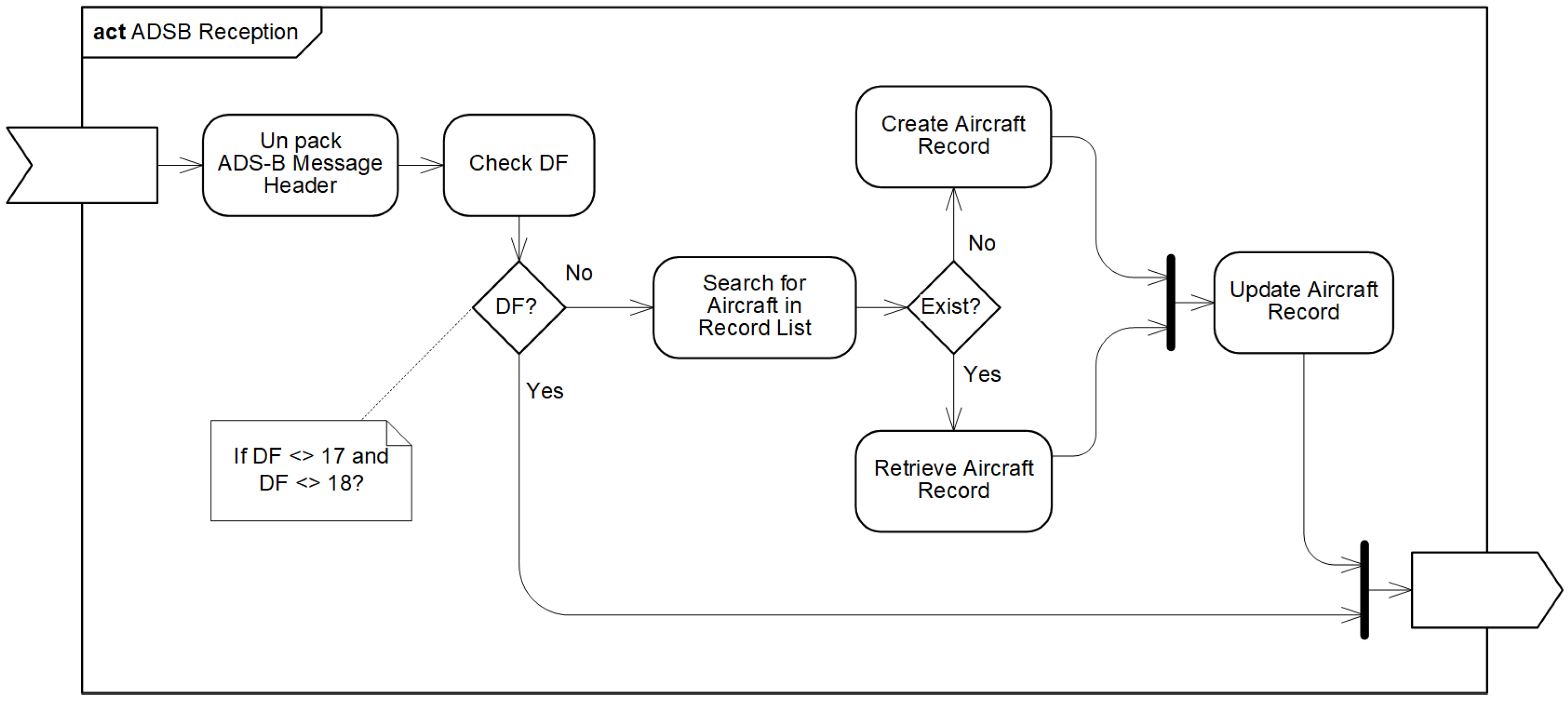
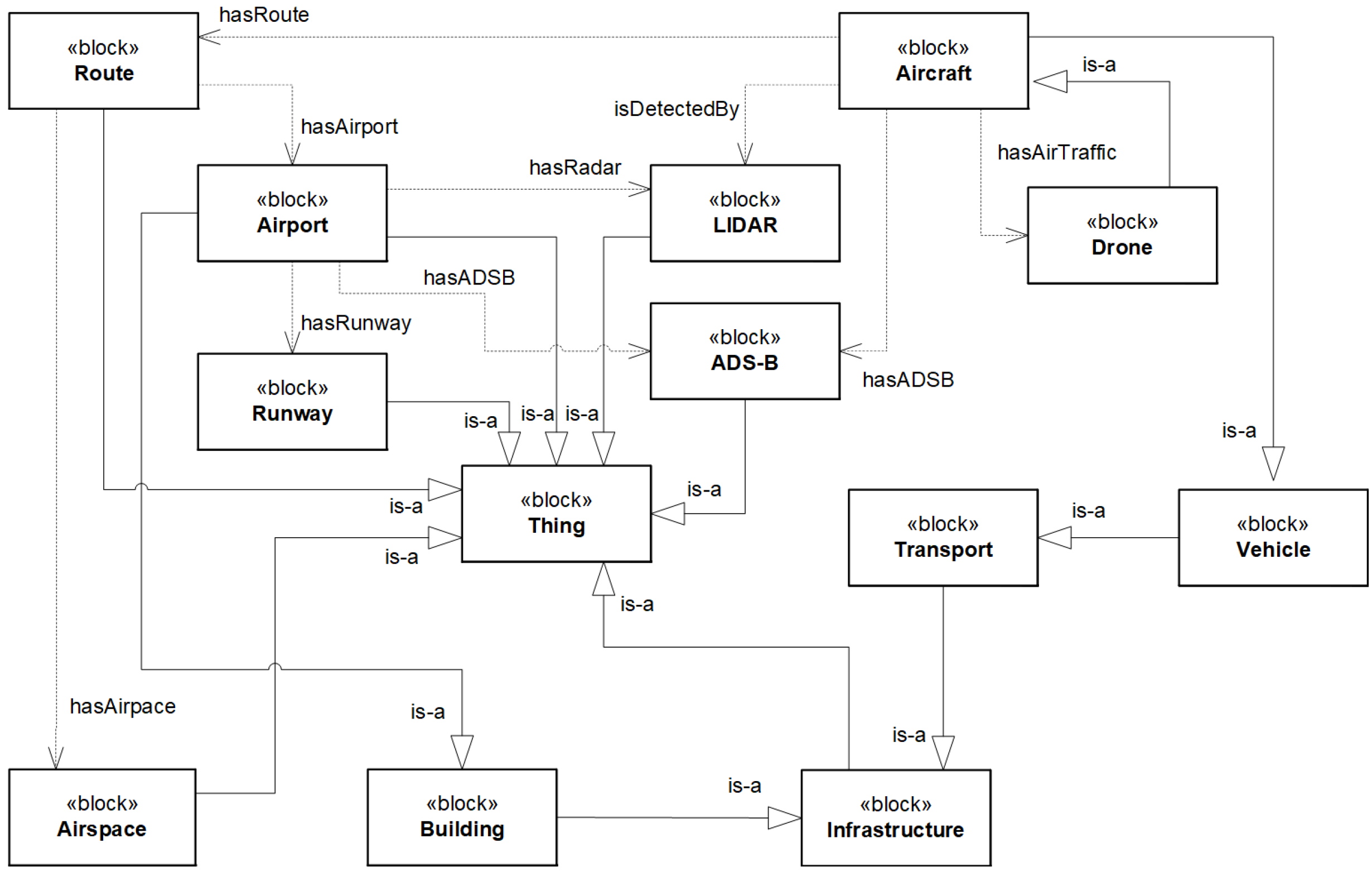
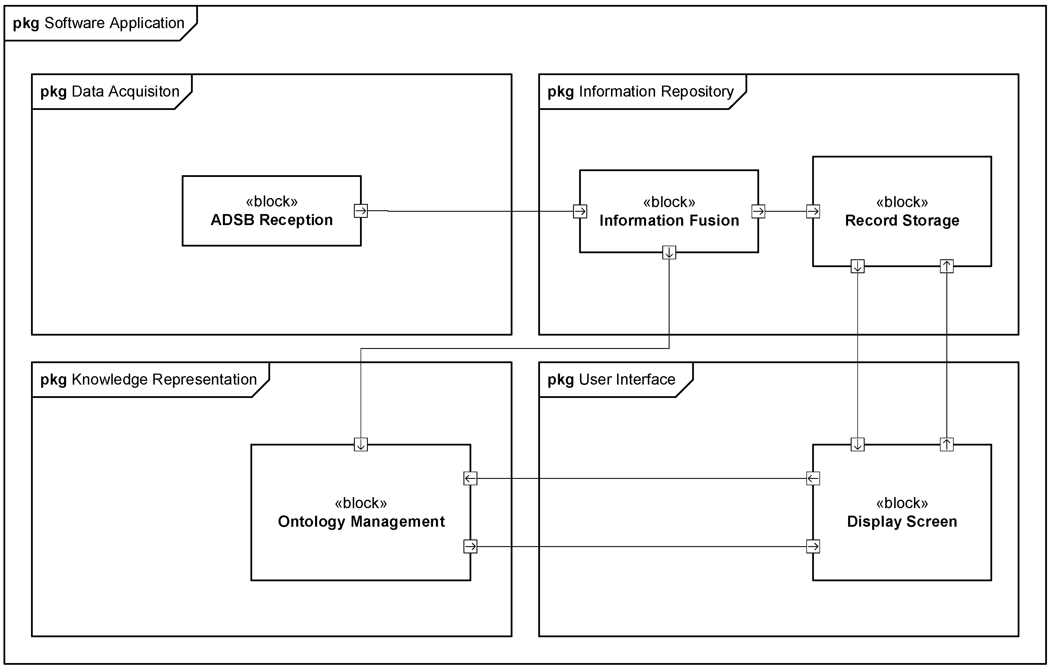
4. Framework Prototype

This section presents the AAO-based DSS framework prototype, including application scenarios used to show the performance of the ontological airspace situational awareness approach for decision system support.

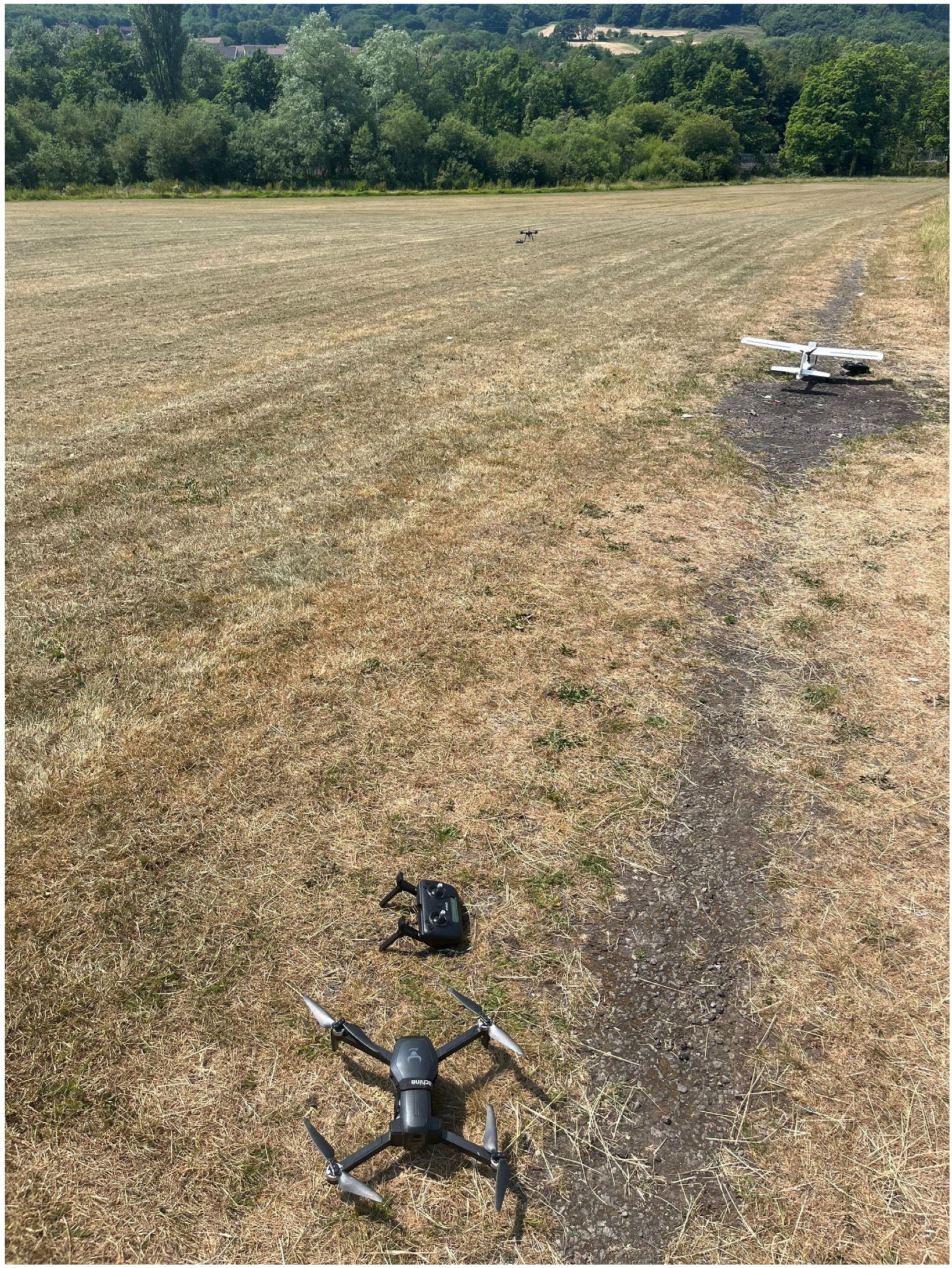
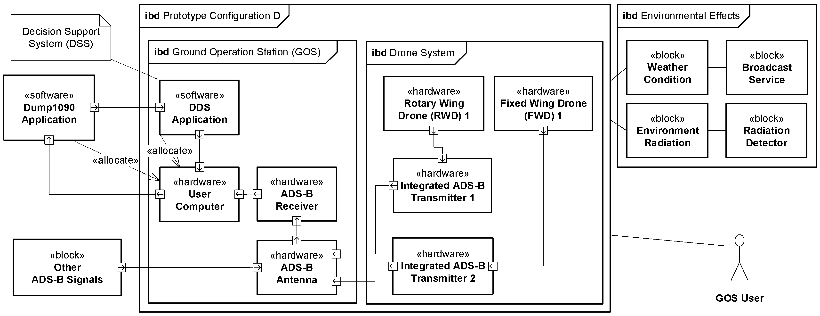
4.1. Hardware Prototype for the Framework

The hardware platform for the framework prototype consists of a laptop computer to run the DSS software application and three small model aircraft that are Radio Control or Remote Control (RC) aircraft (an airplane and two quadcopters). A FlightAware dongle [46] and antenna are used to pick up ADS-B messages from aircraft. The antenna gain allows for the collection of ADS-B messages from any ADSB-equipped aircraft flying nearby (around 50 miles approximately). The UAVs are a Fixed-Wing Drone (FWD) and two Rotary-Wing Drones (RWDs). The FWD plays the role of an airplane that is a Manned Aerial Vehicle (MAV) in specific flight phases, and the RWDs play the role of potential flying intruders (UAVs). The drones (real picture shown in Appendix C) are as follows:
  • FWD1 (RC airplane): Volantex RC Ranger EX [47] equipped with an ADS-B transmitter (uAvionix Echo Sky 2 [48]).
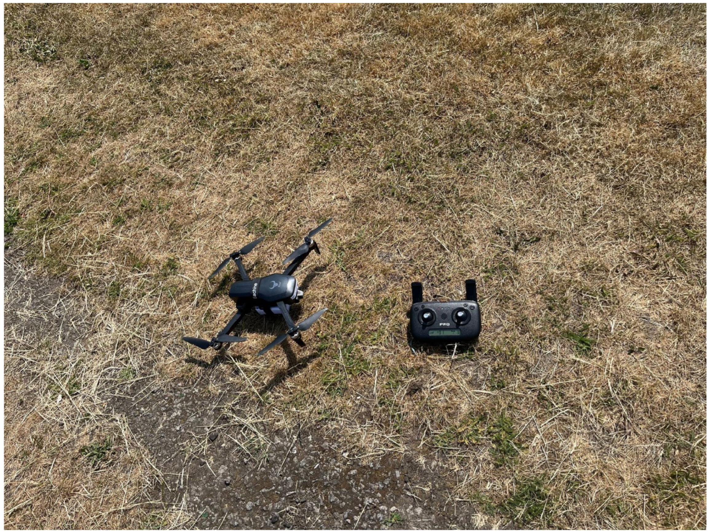
  • RWD1 (RC quadcopter): ZLL SG906 Pro 5G WIFI FPV With 4K HD Camera 2-Axis Gimbal Optical Flow Positioning Brushless RC Drone Quadcopter RTF [49] equipped with an ADS-B transmitter.
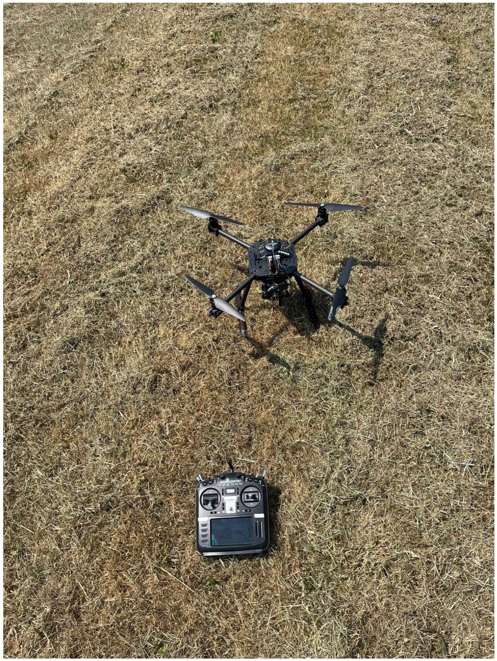
  • RWD2 (RC quadcopter): Holybro X500 Pixhawk 4 Mini 500 mm Wheelbase Frame Kit Combo 2216 880 KV Motor 1045 Propeller for RC Drone [50] equipped with an ADS-B transmitter.
Figure 3 shows a representation of the connections between different modules and elements of the framework prototype.
Figure 3 shows a general connection between aircraft and the GOS; not all the blocks that represent the RC Aircraft block are included. Each of the RC aircraft is equipped as follows:
  • FWD1 (RC airplane; main role: passenger aircraft): ADS-B antenna and transmitter, battery, power manager, flight controller, motor driver, motor, servo driver, and servo.
  • FWD2 (RC airplane; main role: drone): ADS-B antenna and transmitter (optional), battery, power manager, flight controller, motor driver, motor, servo driver, and servo.
  • RWD1 (RC quadcopter; main role drone): battery, power manager, flight controller, motor driver, and motors.
  • RWD2 (RC quadcopter; main role drone): ADS-B antenna and transmitter, battery, power manager, flight controller, motor driver, motors, and telemetry transceiver and antenna.

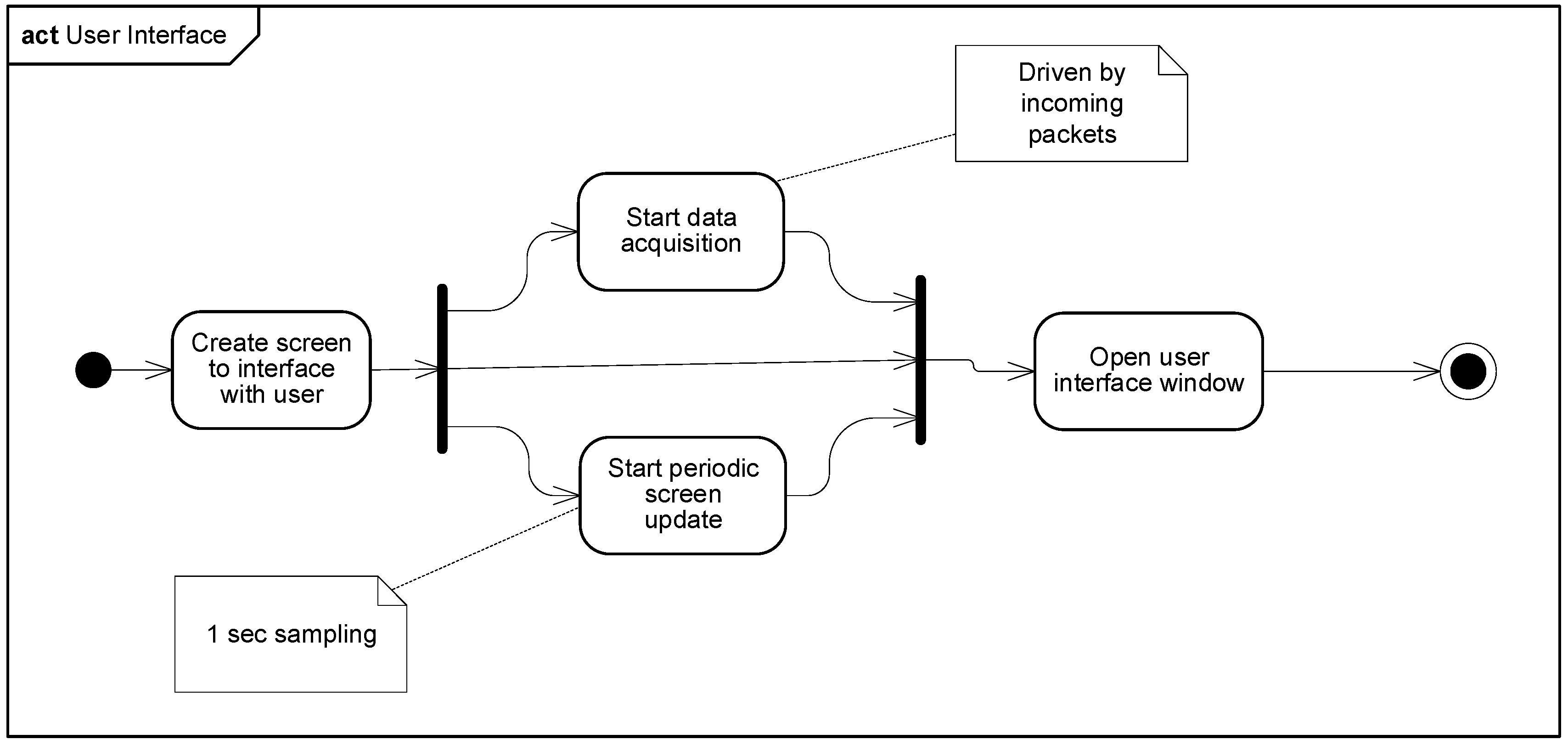
4.2. Software Prototype for the Framework

The software application is developed in the Java programming language, using the Eclipse Integrated Development Environment (IDE). It consists of four Java packages: (1) surveillance data acquisition, (2) a flight information repository, (3) knowledge representation and reasoning, and (4) a user interface.
Figure 4 shows a structural representation of the connections between blocks (classes) that belong to the four software packages. Figure 4 also shows the structure of the relation between packages.
Surveillance data are collected from the ADS-B Reception Block (class) and the LIDAR Sensing Block (class) of the Data Acquisition package. These two blocks feed the Record Storage Block (class) in the information repository package, where records of the aircraft are kept. There is a record for each air vehicle detected. Once the record storage is updated (based on the sampling rate given by the ABS-B package arrival and the LIDAR sampling time), the airspace situation analysis is triggered, and the AAO carries out the cognition required to study potential mid-air collisions. In parallel, information is displayed in the Display Screen block (class) in the user interface package. Results from the AAO analysis are also updated in the Display Screen block so stakeholders are aware of the airspace situation under the radar of the DSS.
Figure 5 shows a behavioral representation of the connections between processes that belong to the user interface package. Figure 5 also helps see the interaction and the relation between processes.
Appendix B shows more details about the data acquisition process and main elements of the AAO.

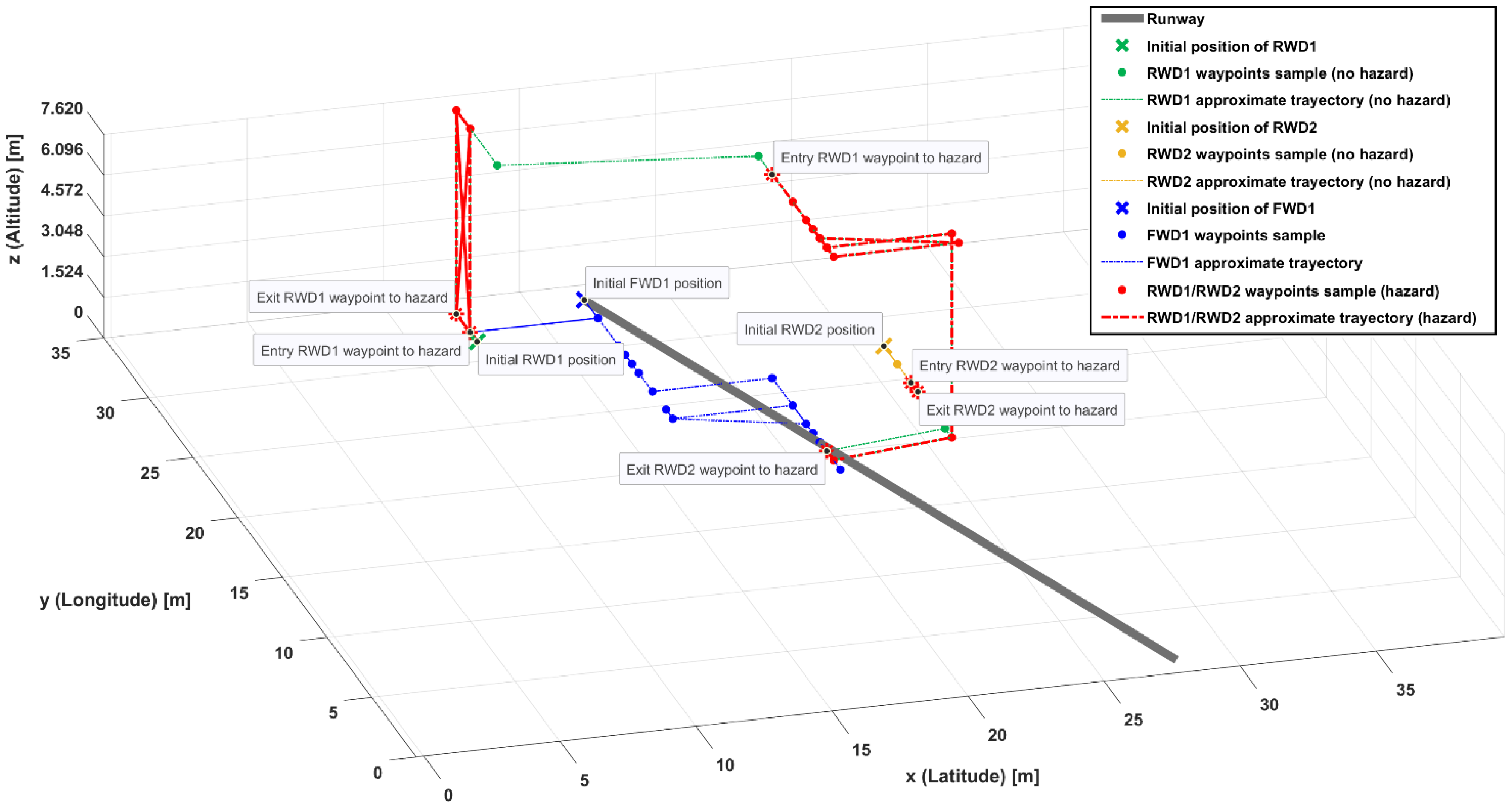
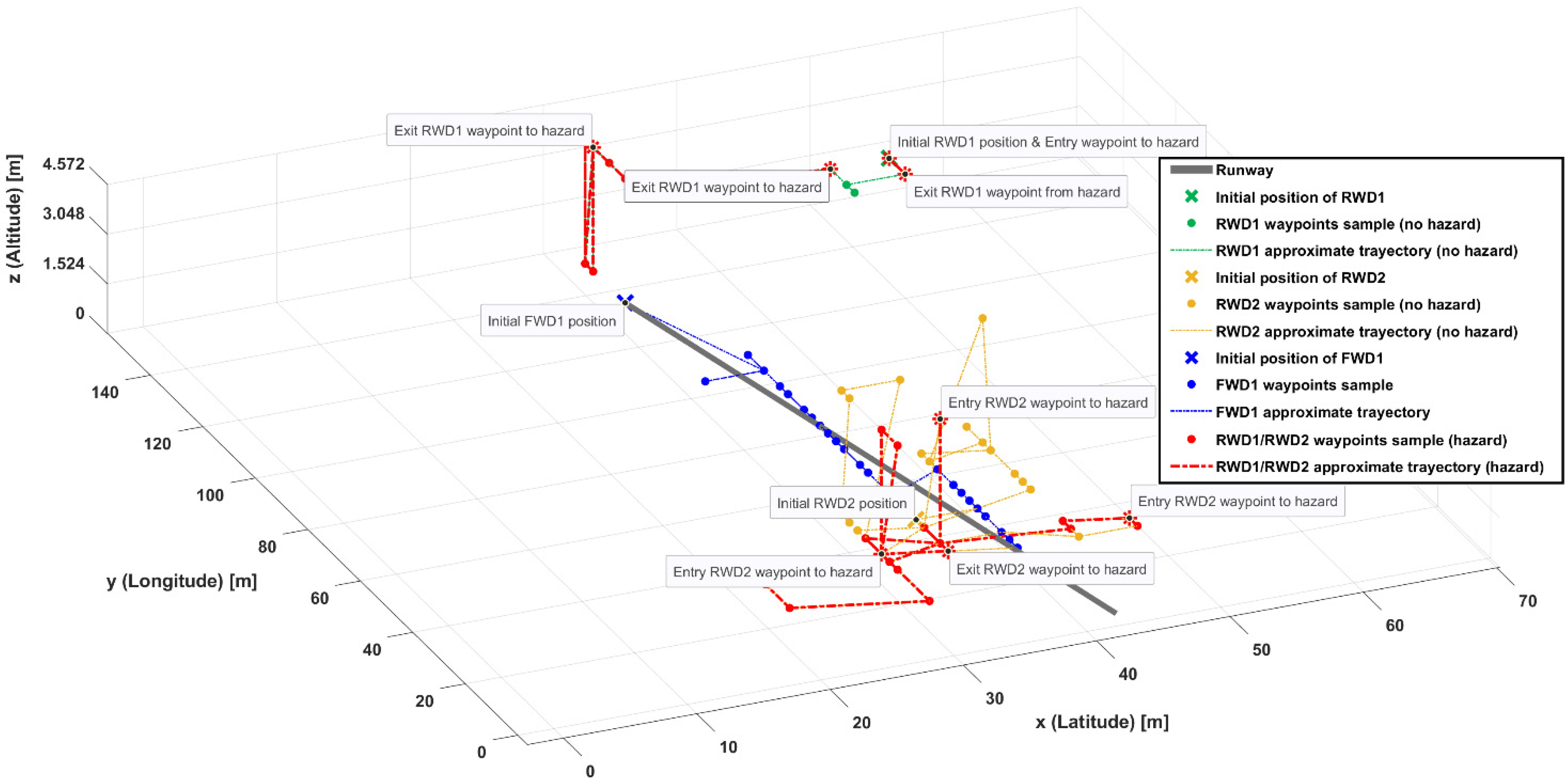
4.3. Air Traffic Scenarios for Experiments

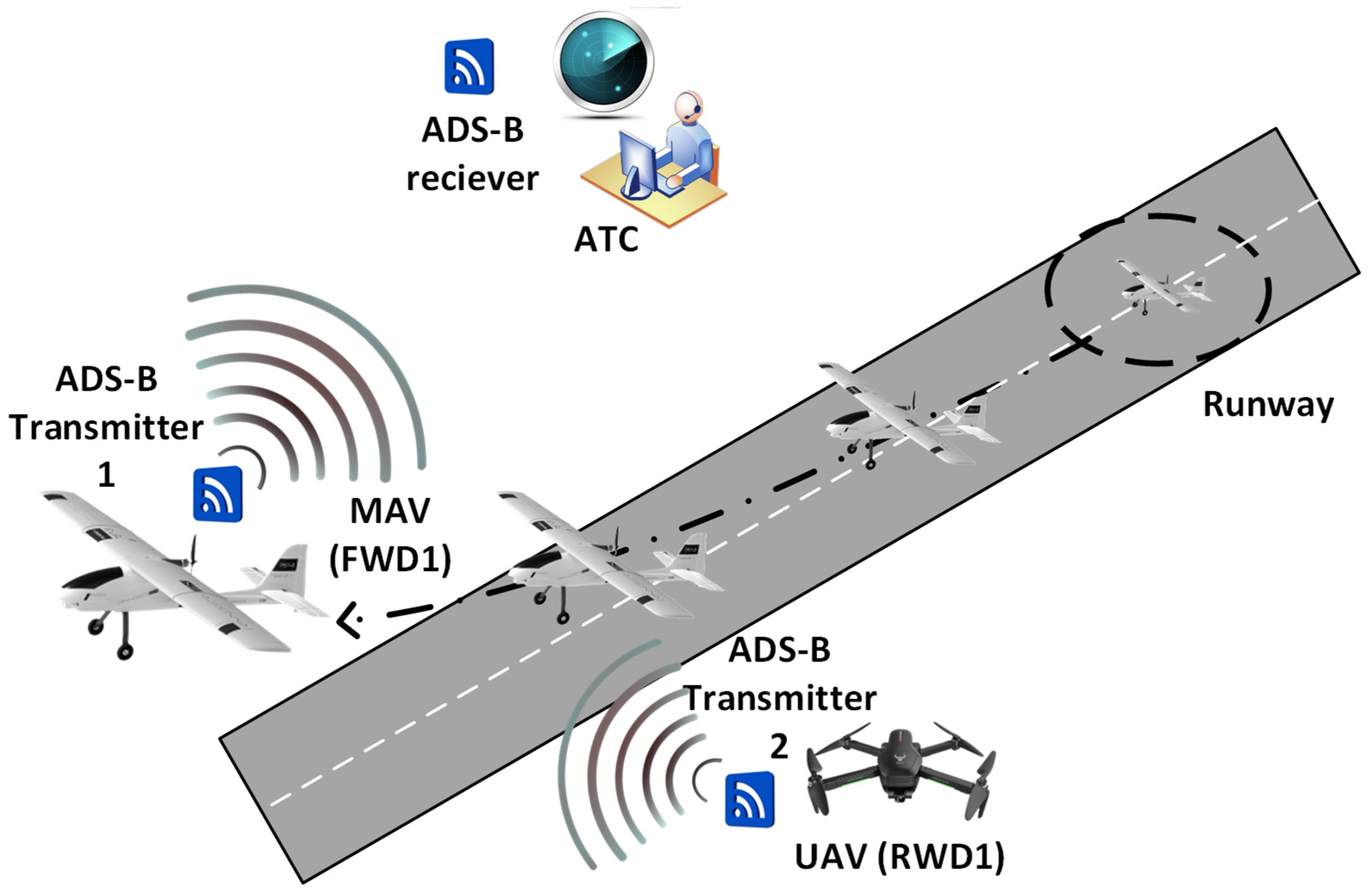
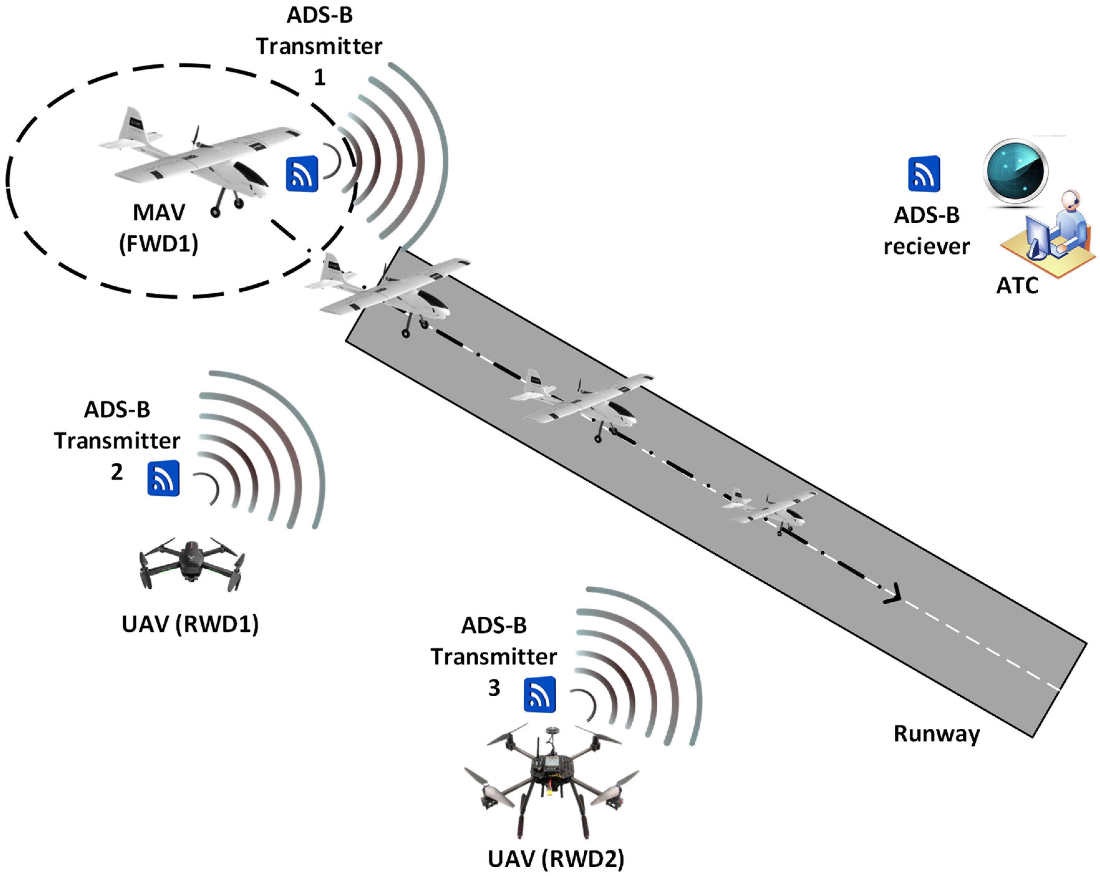
4.3.1. Scenario 1: Airplane Take Off in the Presence of UAVs

The flight phase considered in application Scenario 1 is the takeoff of FWD1 representing a Manned Air Vehicle airplane (MAV) from a runway, while RWD1 represents a UAV flying near the runway with a chance of becoming dangerous for the airplane as the UAV is considered “intruder”. The airplane is assumed to be known as an air vehicle; e.g., it could well represent a commercial aircraft such as a Boeing 737 from an airliner. The drones are recreational quadcopters and a fixed-wing drone. Figure 6 shows application Scenario 1.
One of the three drones has a contactable remote pilot, while the remaining drones have a non-contactable remote pilot. The contactable remote pilot can cooperate with the ATC to avoid collision with the airplane. In addition, the drones that have no pilot contact are equipped with ADS-B. The airplane also has ADS-B as per aviation regulations. The initial position of the airplane is taxied at one end of the runway, and it is ready for takeoff. The drones are initially located as shown in Figure 6.
Aircraft localization is essential for collision avoidance and is carried out by means of surveillance radars and cutting-edge technologies such as ADS-B and LIDAR technology. Surveillance systems based on ADS-B and LIDAR devices (ADSB transmitters/receiver and PSR) are shown in Figure 6.

4.3.2. Scenario 2: Airplane Landing in the Presence of UAVs

The flight phase considered in application Scenario 2 is the landing of FWD1, which represents a MAV approaching a runway, while RWD1 represents a UAV flying near the runway with a chance of the situation becoming dangerous for the airplane, as RWD1 is considered “intruder”. The airplane is assumed to be a known air vehicle; e.g., it could well represent a commercial aircraft such as an Airbus 350 from an airliner. The drones are two recreational quadcopters and a fixed-wing drone. Figure 7 shows the aircraft landing application Scenario 2.
Two of the three drones have a contactable remote pilot, while the remaining drone has a non-contactable remote pilot. The contactable remote pilots can cooperate with the ATC to avoid collision with the airplane. In addition, the drones that have no pilot contact are equipped with ADS-B. The airplane also has ADS-B as per aviation regulations. The initial position of the airplane is approaching the runway, and it is becoming ready for landing. The drones are initially located as shown in Figure 7. Aircraft localization is carried out by means of surveillance radars and cutting-edge technologies such as ADS-B and LIDAR technology. Surveillance systems based on ADS-B and LIDAR devices (ADS-B transmitters/receiver and PSR) are shown in Figure 7.

5. Experimental Application Results

This Section presents the experimental results obtained from outdoor testing trials carried out in a park for two application scenarios.

5.1. Setup of the Application Scenarios

The park-testing trials involve a computer (GOS) running the Dump1090 software and the DSS software application. Application Scenario 1 is carried out by using the framework prototype configuration shown in Figure 8.
Two physical drones, RWD1 and FWD1 (both equipped with ADS-B transmitters), are used in this scenario. FWD1 plays the role of an airplane that is about to take off (e.g., a commercial airplane). RWD1 plays the role of a drone flying near the runway FWD1 takes off from. FWD1 is initially taxied to a location, which is one end of the runway. Then, FWD1 starts its run on the runway (as part of the takeoff operation).
Figure 9 shows details of the interaction between key framework prototype elements from application Scenario 1.
Application Scenario 2 is carried out by using the framework prototype configuration shown in Figure 10.
Two physical drones, RWD1 and FWD1 (both equipped with ADS-B transmitters), are used in Scenario 1. FWD1 plays the role of an airplane that is about to take off (e.g., a commercial airplane). RWD1 plays the role of a drone flying near the runway FWD1 takes off from. FWD1 is initially taxied to a location, which is one end of the runway. Then, FWD1 starts its run on the runway (as part of the takeoff operation).
Figure 11 shows details of the interaction between key framework prototype elements from application Scenario 2.
Three physical drones (RWD1, RWD2, and FWD1, all of them equipped with ADS-B transmitters) are used in application Scenario 2. FWD1 plays the role of an airplane (e.g., a commercial airplane) that is landing. FWD1 has already touched the ground, and it is running on the runway on its way to stop close to one of the ends of the runway. RWD1 and RWD2 play the role of drones flying near the runway where FWD1 is landing.
Table 1 shows some details of environmental aspects from the park-testing trials for both application scenarios.
The separation between aircraft is calculated as the length of the vector defined by the two positions of the aircraft in question. Thus, it is based on geographic point locations by coordinates such as latitude, longitude, and altitude. The downscaled scenarios involve short distances for which conversation to Cartesian coordinates is not required. Therefore, the calculation of the distance between drones and the target airplane (Airplane 1) is calculated by means of the following Formula (1):
d = l a t R W D x l a t F W D 1 2 + l o n g R W D x l o n g F W D 1 2 + a l t R W D x a l t F W D 1 2
The distance d is measured in units and then converted to meters for better understanding when used in figures. Likewise, latitude, longitude, and altitude are plotted in meters. It is used to update the AAO for each of the drones (RWD1 and RWD2) flying near the airplane (FWD1).
The AAO (through the user interface) populates for levels of SAW:
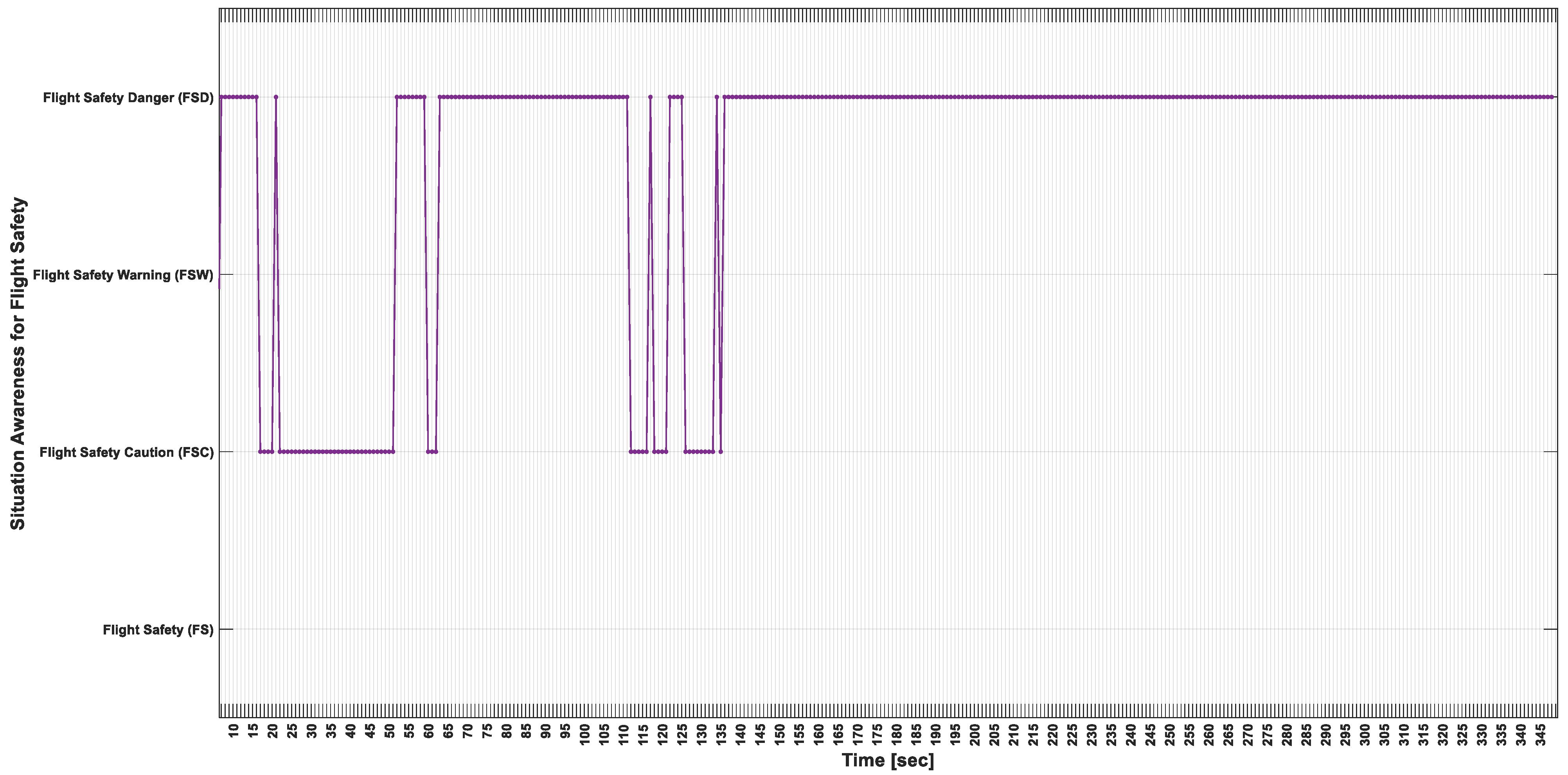
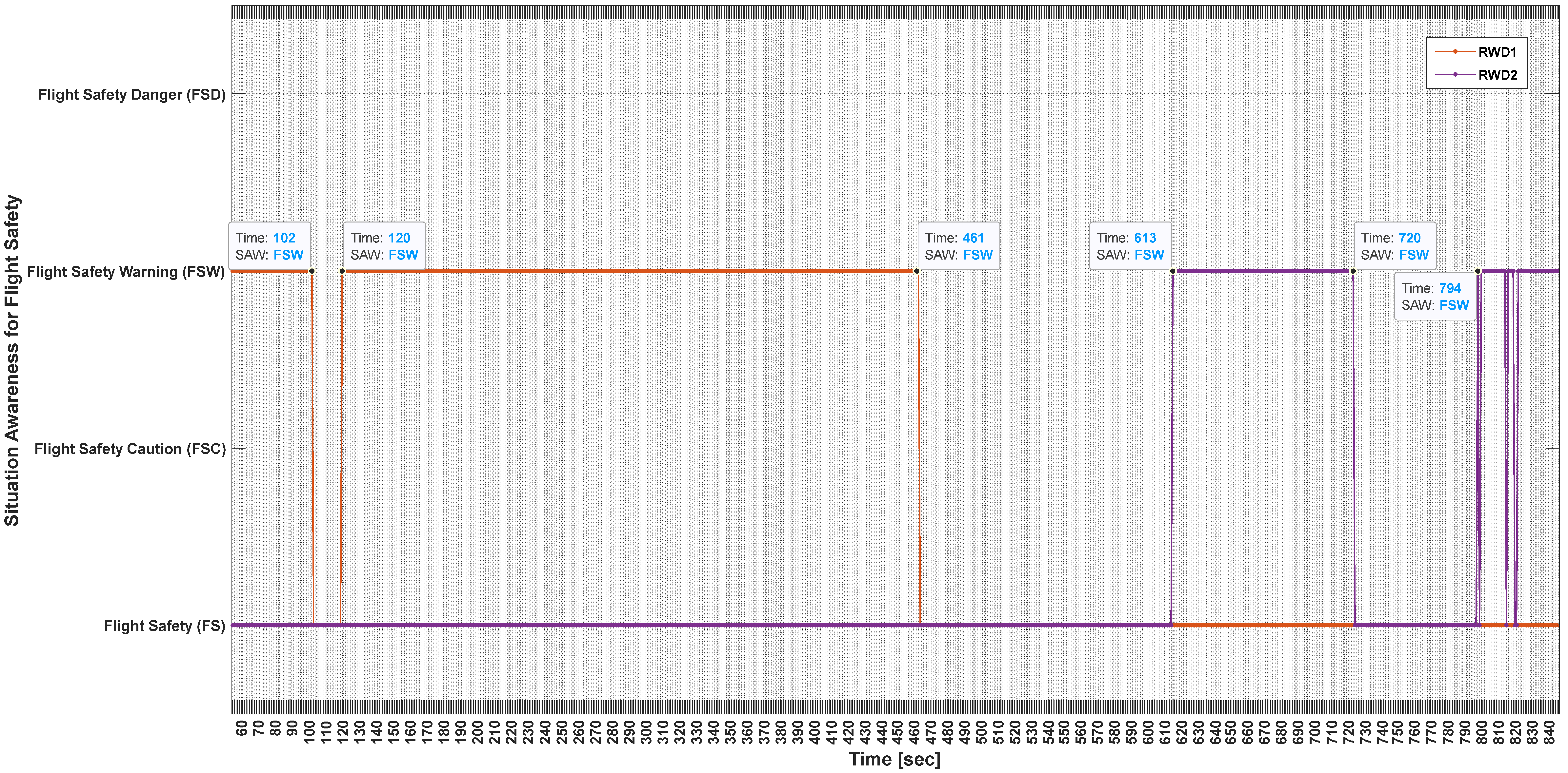
  • Flight Safety Danger (FSD). This SAW is basically triggered and displayed to the user when the RWDs are closer to the FWD1 than is permitted and there is no countermeasure in place to avoid a collision.
  • Flight Safety Warning (FSW). This SAW is basically triggered and displayed to the user when the RWDs are closer to the FWD1 than is permitted and there is some countermeasure in place to avoid collision.
  • Flight Safety Caution (FSC). This SAW is basically triggered and displayed to the user when the RWDs are close to the FWD1 (within the permitted separations) and there is no countermeasure in place to avoid a collision.
  • Flight Safety (FS). This SAW is basically triggered and displayed to the user when the RWDs are close to the FWD1 (within the permitted separations) and there is some countermeasure in place to avoid a collision.
The DSS software application is meant to run on a computer alongside ATCs for the scenarios presented in this paper. However, plans are for it to be implemented on onboard computers installed in airplanes (to be used by pilots) as well as UAVs for autonomous navigation. The point is that the DSS users take into account the outputs from the DSS, i.e., FS, FSC, FSW, and FSD, to make their decisions in airspace situations. The DSS is not initially meant to replace ATCs, pilots, and other relevant users, but it is an option that can be considered in the future.

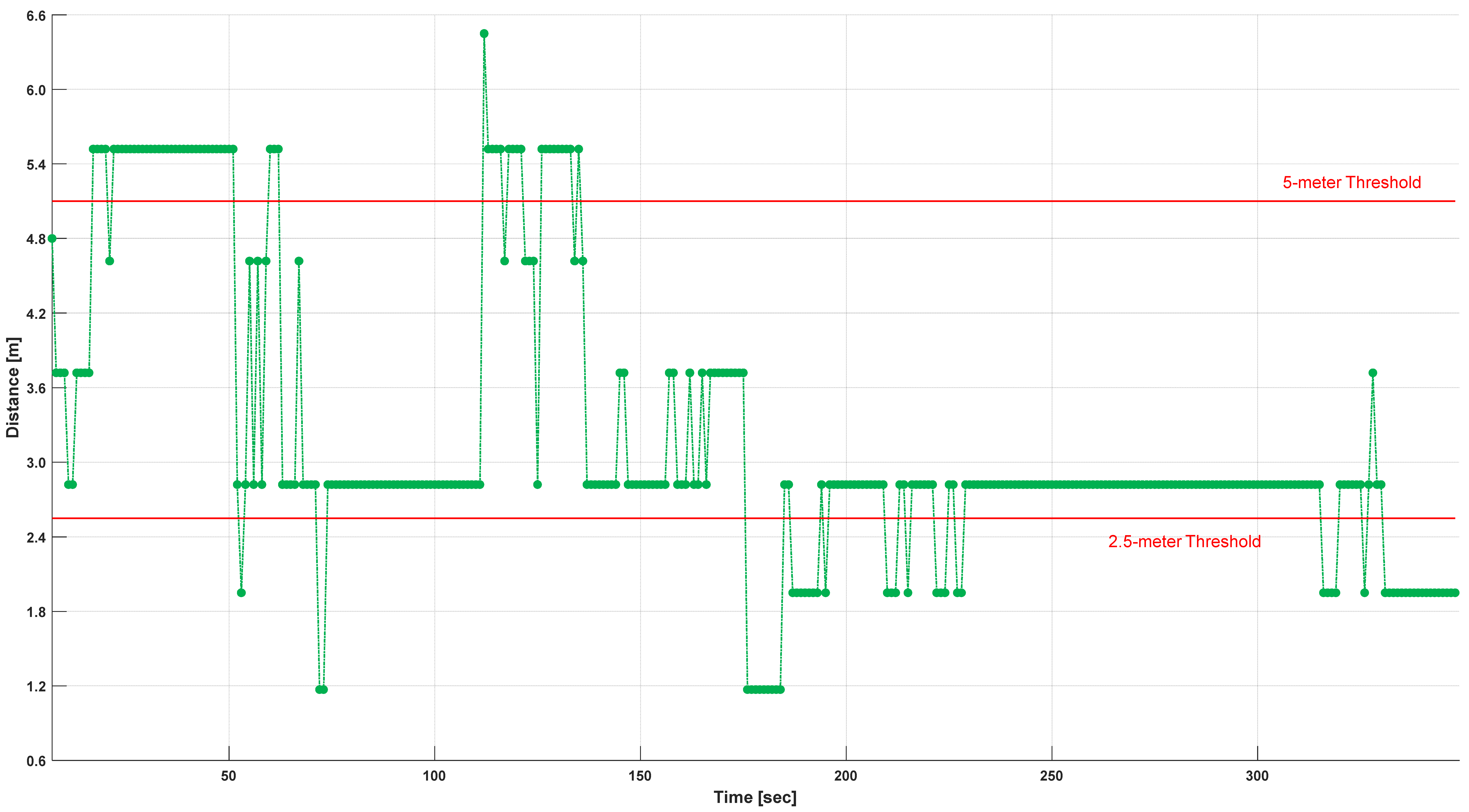
5.2. Scenario 1 Results: Airplane Rolling Out for Takeoff

The operation of the aircraft (RWD1 and FWD1) is meant to replicate (downscale) a real airspace scenario where an airplane (e.g., a commercial airliner represented by FWD1) is taking off while a UAV (represented by RWD1) flies around. FWD1 takes off from one of the ends of the runway.
This Subsection presents the experimental results from application Scenario 1 (takeoff) with real values for latitude, longitude, and altitude. Figure 12 and Figure 13 show flight areas and waypoints, which imply hazards of potential collision between aircraft (RWD1 and FWD1, both real drones). The closest distance that the aircraft can be without becoming a hazard is set at 170 units (~5 m/~15 feet for downscaled aircraft, i.e., drones) for drones in front and in the direction of the airplane (FWD1) and 85 units (~2.5 m/~7.5 feet) for drones behind and not in the direction of the airplane (FWD1). A unit is ~30 cm.
Figure 12 shows the trajectory produced by ADS-B transmitter 1, mounted in RWD1 (in green), with the following setting: aircraft unauthorized to fly, and countermeasure (“PilotContact”, which means the UAV has a remote contactable pilot that can be reached in case of any maneuver required to keep the UAV and the MAV in question properly separated) for a possible mid-air collision. RWD1 is initially located (green cross) at one of the ends of the runway (straight line in dark grey) where FWD1 is taxied (blue cross) and ready to take off at the beginning of the runway, the other end of the runway. The trial’s duration is 307 s (5 min 7 s). Note that, because the small UAVs were used to emulate the test scenario, small variations in the position based on accuracy could appear to violate the actual scenario. Hence, an error of 1 m could make it appear that the UAV was off the runway, while in reality, the 1 m distance is within the margin of error of the test scenario.
RWD1 is initially placed on the opposite side of the runway (green cross), which does not imply a hazard for FWD1 (green line) until its green trajectory line becomes red as RWD1 becomes close to FWD1 (all the red lines along the RWD1 trajectory). Figure 12 is a 3D representation (space coordinates), although it includes a 4th dimension, i.e., the time elapsed in the trial.
Figure 13 shows the distance between RWD1 and FWD1 for each sampling time (every 1 s) in the DSS software application. The distance is calculated as a vectorial difference between the ADSB-based localization of the two drones (RWD1 and FWD1).
If RWD1 is behind FWD1 (opposite to the direction of FWD1), the reference distance to determine whether RWD1’s flight is a hazard for FWD1 is 85 units. If RWD1 is ahead of FWD1 (in the direction of FWD1), the reference distance to determine whether RWD1’s flight is a hazard for FWD1 is 170 units. Both reference distances are highlighted in Figure 13. There is a critical period when the two aircraft (RWD1 and FWD1) become very close (no collision); the current distance calculated is 0 units (177 and 178 s).
Figure 14 shows the SA provided by the DSS software application for the duration of the experiment. The possible outputs for this trial are Flight Safety (FS), where the airplane (FWD1) under consideration is not at risk of collision with the relevant AUV (RWD1), and Flight Safety Warning (FSW), where the airplane (FWD1) under consideration is at considerable risk of collision with the relevant AUV (RWD1).
There are two times (171 s and 199 s) during the transition of the SA states in which values for the SA bounce. This is due to interim changes in the calculation of the distance between aircraft that suggest the threshold given by the limit distance is crossed, and then it is not crossed for a sample period.
In this experiment, the activation (reasoning behind scenes) of knowledge from the ontology is as follows.
Perception: (Description Logic rules in Appendix A)
  • FWD1 is an airplane, which is an aircraft; (A4) and (A1).
  • RWD1 is a quadcopter, which is an aircraft; (A5) and (A1).
  • FWD1 and RWD1 are in Airspace 1; (A15) and (A16); as an airspace having air vehicles, (A3). Hence, RWD1 and FWD1 are in the same airspace (Airspace 1). Thus, RWD1 is part of the air traffic of FWD1 (and vice versa); (A1).
  • Airspace 1 is a controlled airspace; (A17).
  • RWD1 is not authorized to fly in Airspace 1; (A10).
  • RWD1 has a contactable pilot; (A12).
Comprehension:
  • Separation is a requirement; (A23). Aircraft have a requirement for separation; (A24). Then, FWD1 and RWD1 have a requirement of separation.
  • FWD1 requires a separation of 170 units from intruders when intruders are ahead of it and 85 units when intruders are behind it; (A25).
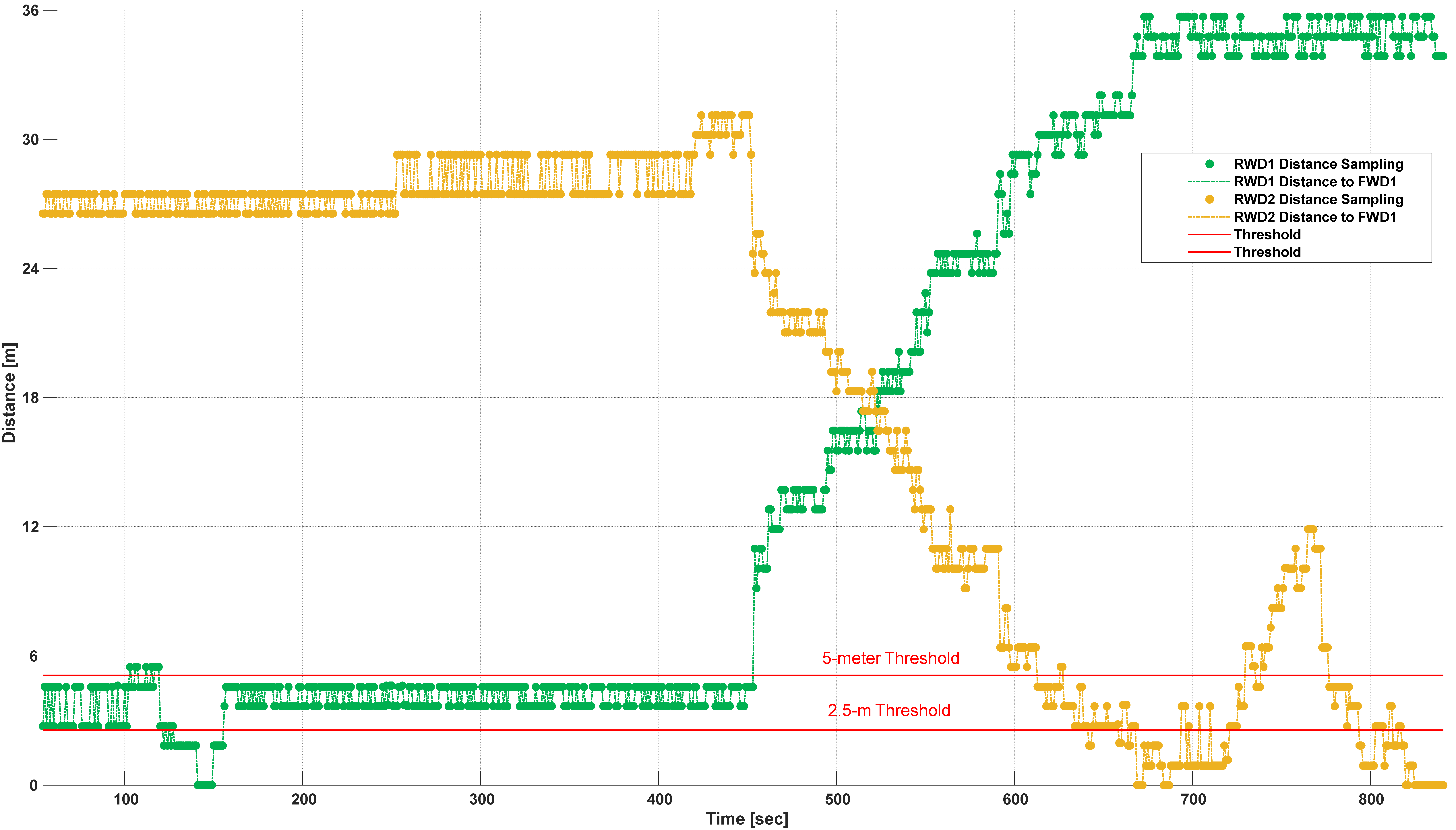
  • RWD1 is at a distance from FWD1 (distance continuously being updated).
  • Proper separation is when RWD1 is further from FWD1 than the separation distance; (A27).
  • Improper separation is when RWD1 is closer to FWD1, less than the separation distance or the opposite of proper separation; (A28).
  • Aircraft have a requirement to have proper separation; (A26). Thus, FWD1 and RWD2 have the same requirement, as they are aircraft.
  • Proper separation can avoid a mid-air collision; (A27).
  • RWD 1 is an intruder; (A29), as it is not authorized to fly in the same airspace as FWD1, as per (A17).
  • Intruders can infringe on safety; (A30), which is a status; (A31).
  • Aircraft have a constraint that is no collision; (A35).
  • Aircraft have safety; (A36).
  • RWD1 has separation from FWD1; (A37).
  • RWD1 has a direction (ahead of FWD1 or behind it); (A38).
  • RWD2 has separation from FWD1; (A39).
  • RWD2 has a direction (ahead of FWD1 or behind it); (A40).
  • Contactable pilot is a counter measure; (A41).
  • None as a countermeasure means no countermeasure; (A42).
  • RWD1 has no countermeasure; (A43).
  • RWD2 has a countermeasure that is a contactable pilot; (A44).
Projection:
  • Flight safety caution is when RWD1 becomes close to FWD1 (further than the required separation; (A56). Queries on this class/concept show the airplane in caution, FWD1 in this case. Caution comes from RWD1 not having a countermeasure (None).
  • What causes a flight safety caution is a UAV near an airplane (FWD1); (A57). Queries on this class/concept show the UAV causing the caution, RWD1 in this case since it does not have countermeasures.
  • Flight safety danger is when RWD1 becomes close to FWD1 (closer than the required separation; (A61). Queries on this class/concept show the airplane in danger, FWD1 in this case. The danger comes from RWD1 not having a countermeasure (None).
  • What causes a flight safety danger is a UAV near an airplane (FWD1); (A62). Queries on this class/concept show the UAV causing the danger, RWD1 in this case since it does not have countermeasures.
Figure 15 shows the trajectory produced by the ADS-B transmitter mounted in RWD1 with the following setting: aircraft unauthorized to fly, with no countermeasure (None) for possible mid-air collision. RWD1 is initially located at the beginning of the runway (straight line in dark grey) near FWD1, which is taxied (blue cross) to be ready to take off. The trial’s duration is 1142 s (19 min 2 s).
RWD1 is initially just ahead of FWD1, which does not imply a hazard for FWD1 (green cross). Then, RWD1 flies around FWD1, moving toward it (red line), which is a hazard for FWD1. As FWD 1 moves forward for takeoff, RWD1 goes behind FWD1 and flies in the opposite direction to FWD1. Thus, RWD1 becomes no hazard for FWD1 (green line). Then, RWD1 flies above FWD1 (y = 0–120), and RWD1 becomes a hazard for FWD1 as they become close again. RWD1 is eventually not a hazard in its final position ~(x = 40, y = 0). Figure 15 is a 3D representation (space coordinates), although it includes a 4th dimension (the time elapsed in the trial).
Figure 16 shows the distance between RWD1 and FWD1 for each sampling time (every 1 s) in the DSS software application for a duration of 342 s. The distance is calculated as a vectorial difference between the ADSB-based localization of the two drones (RWD1 and FWD1).
If RWD1 is behind FWD1 (opposite to the direction of FWD1), the reference distance to determine whether RWD1’s flight is a hazard for FWD1 is 85 units. If RWD1 is ahead of FWD1 (in the direction of FWD1), the reference distance to determine whether RWD1’s flight is a hazard for FWD1 is 170 units. Both reference distances are highlighted in Figure 16.
Figure 17 shows the SAW provided by the DSS software application for the 342 s (from the beginning) of the experiment. The possible outputs for this trial are Flight Safety Caution (FSC), where the airplane (FWD1) under consideration is at moderate risk of collision with the relevant UAV (RWD1), and Flight Safety Danger (FSD), where the airplane (FWD1) under consideration is at high risk of collision with the relevant UAV (RWD1).
RWD1 is ahead of FWD1 in the first 342 s of the experimental trial. There are a few times during the transition of SA states in which values for the SAW switch. This is due to a calculation as discussed in Figure 14.

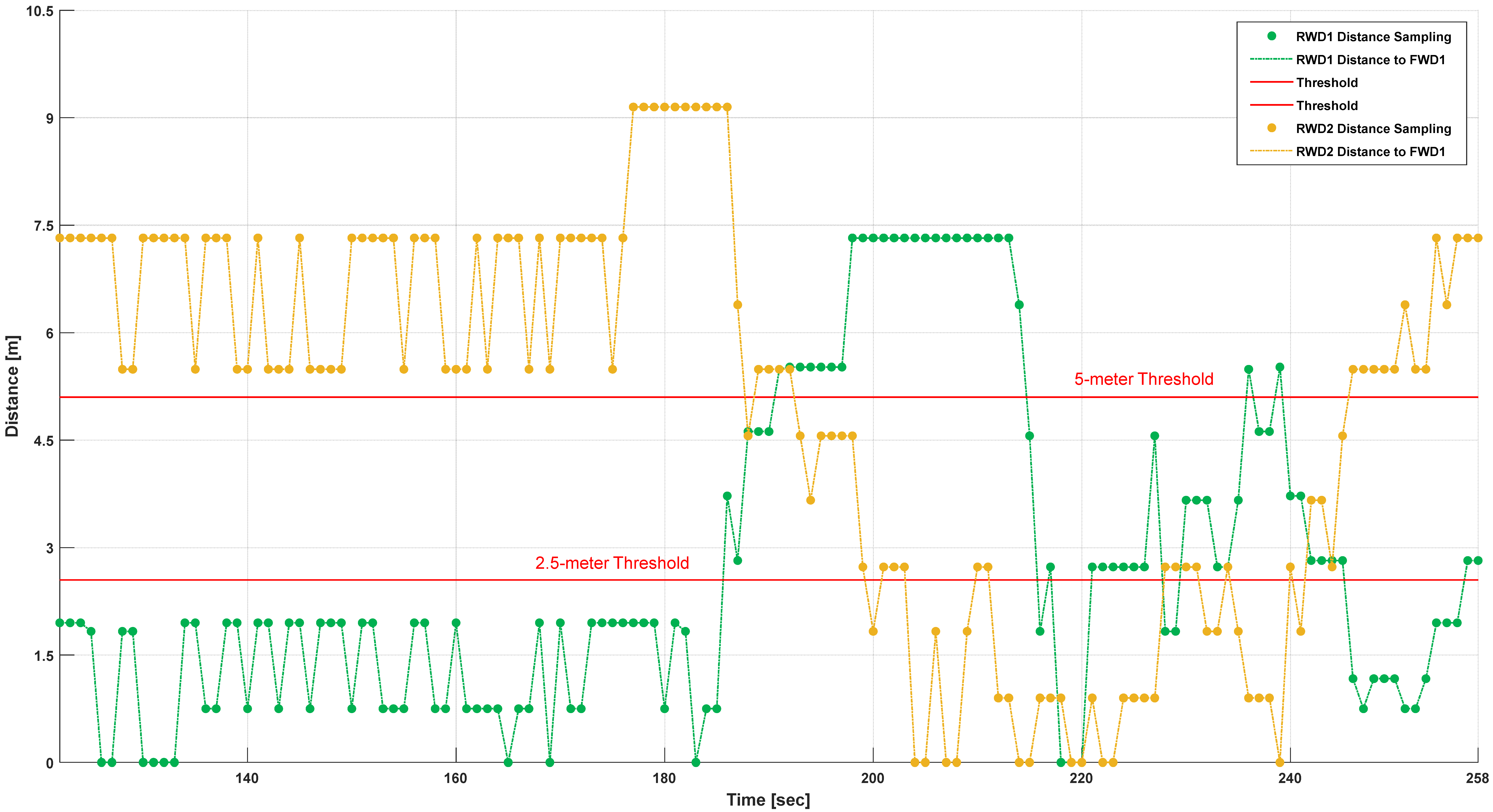
5.3. Scenario 2 Results: Airplane During After-Landing Roll Out

The operation of the aircraft (RWD1, RWD2, and FWD1) is meant to replicate (downscale) a real airspace scenario where an airplane (e.g., a commercial airliner represented by FWD1) is landing while UAVs (represented by RWD1 and RWD2) fly around. FWD1 lands by touching down one of the ends of the runway.
This Subsection presents the experimental results from application Scenario 2 with real values for latitude, longitude, and altitude (not normalized as in the office and garden testing trials). Figure 18 and Figure 19 also show details of areas (flight waypoints) that imply potential collisions between aircraft (RWD1, RWD2, and FWD1; real drones used). The closest distance that the aircraft can be without becoming a hazard is set at 170 units for drones in the front and in the direction of the airplane (FWD1) and 85 units for drones behind and not in the direction of the airplane (FWD1).
Figure 18 shows the trajectory produced by ADS-B transmitter 1, mounted in RWD1 (in green), with the following setting: aircraft unauthorized to fly and no countermeasure (“none”) for possible mid-air collision. It also shows the trajectory produced by ADS-B transmitter 3, mounted in RWD2 (in yellow), with the following setting: aircraft unauthorized to fly and countermeasure (“PilotContact”, which means the UAV has a remote contactable pilot that can be reached in case of any maneuver required to keep the UAV and the MAV in question properly separated) for a possible mid-air collision.
RWD1 is initially located (green cross) at one of the ends of the runway (straight line in dark grey) where FWD1 has just touched down for landing (blue cross), and it is moving from this end of the runway to the other end of the runway. RWD1 does not pose a hazard for FWD1 as it is at a safe distance from FWD1 (green cross and line). For the next sample, RWD1 becomes a hazard for FWD1, given the separation between them for the following samples (red line). Then, RWD1 flies apart from FWD1 (green line) until it becomes close to FWD1 again as they are moving forward along the runway (red line). RWD2 is initially on the other side of the runway (yellow cross), and it flies a bit forward. RWD2 does not pose any hazard for FWD1 until it becomes close enough to FWD1 (y = 20–25; red line), where it is the last sampled position of RWD2. The trial’s duration is 258 s (4 min 18 s). Figure 18 is a 3D representation (space coordinates), although it includes a 4th dimension (the time elapsed in the trial).
Figure 19 shows the distance between RWD1 and FWD1 as well as RWD2 and FWD1 for each sampling time (every 1 s) in the DSS software application. The distance is calculated as a vectorial difference between the ADSB-based localization of the two pairs of drones (RWD1/RWD2 and FWD1).
If RWD1/RWD2 is behind FWD1 (opposite to the direction of FWD1), the reference distance to determine whether the RWD1/RWD2 flight is a hazard for FWD1 is 85 units. If RWD1/RWD2 is ahead of FWD1 (in the direction of FWD1), the reference distance to determine whether RWD1/RWD2 flight is a hazard for FWD1 is 170 units. Both reference distances are highlighted in Figure 13. There is a critical period when the two aircraft (RWD1/RWD2 and FWD1) are very close (no collision) and for which the current distance calculated is 0 units (177 and 178 s).
Figure 20 shows the SAW provided by the DSS software application for the time the three drones were active during the experiment. The possible outputs for this trial for RWD1 are Flight Safety (FS), where the airplane (FWD1) under consideration is not at risk of collision with one of the relevant AUV (i.e., RWD1), and Flight Safety Warning (FSW), where the airplane (FWD1) under consideration is at considerable risk of collision with RWD1. On the other hand, the possible outputs for this trial for RWD2 are Flight Safety Caution (FSC), where the airplane (FWD1) under consideration is not at risk of collision with the other relevant UAV (i.e., RWD2), and Flight Safety Danger (FSD), where the airplane (FWD1) under consideration is at considerable risk of collision with RWD2.
There are some periods of time (187–191 s and 227–242 s) during the transition of the SAW states in which values for the SAW bounce for RWD2. Likewise, there is an isolated change at 239 s during the transition of the SAW states in which values for the SAW bounce for RWD1. Both situations are due to interim changes in the calculation of the distance between aircraft that suggest the threshold given by the limit distance is crossed and then it is not crossed for a sample period. In the case of RWD 1, proximity to FWD1 is affected by the readings from the GPS of its ADS-B transmitter as the distance is borderline (threshold). In the case of RWD2, RWD2 crosses the threshold distance multiple times.
Figure 21 shows the trajectory produced by the ADS-B transmitters mounted in the drones. Both UAVs (RWD1 and RWD2) are set to be aircraft unauthorized to fly, and both have countermeasures (PilotContact) for a possible mid-air collision.
RWD1 is initially located on the right and the back of Figure 21 (where FWD1 has just touched down for landing; blue cross). RWD1 is a hazard for FWD1 for a short while because of its initial position (y = 120–140; red line), and then RWD1 becomes no hazard (green line), but then it is a hazard again (red line). RWD2 initially lands ahead of the runway. RWD2 is not a hazard for FWD1 (yellow line) until it reaches x = ~ 30, y = ~40, x = ~ 50, and y = ~40 (red line). The trial’s duration is 841 s (14 min 1 s). Figure 21 is a 3D representation (space coordinates), although it includes a 4th dimension (the time elapsed in the trial).
Figure 22 shows the distance between RWD1 and FWD1 as well as RWD2 and FWD1 for each sampling time (every 1 s) in the DSS software application. The distance is calculated as a vectorial difference between the ADSB-based localization of the two pairs of drones (RWD1/RWD2 and FWD1).
If RWD1/RWD2 is behind FWD1 (opposite to the direction of FWD1), the reference distance to determine whether the RWD1/RWD2 flight is a hazard for FWD1 is 85 units. If RWD1/RWD2 is ahead of FWD1 (in the direction of FWD1), the reference distance to determine whether the RWD1/RWD2 flight is a hazard for FWD1 is 170 units. Both reference distances are highlighted in Figure 16.
Figure 23 shows the SAW provided by the DSS software application for the time the experiment computes the SAW for the two drones (i.e., RWD1 and RWD2). The possible outputs for this trial are Flight Safety (FS), where the airplane (FWD1) under consideration has no risk of collision with the relevant AUVs (RWD1 and RWD2), and Flight Safety Warning (FSW), where the airplane (FWD1) under consideration is at considerable risk of collision with the relevant UAVs (RWD1 and RWD2).
When FWD1 touches the runway for landing, RWD1 is ahead of it (first 102 s of the experimental trial). Then, RWD1 is behind FWD1, so distance restrictions relax a bit (from 170 units down to 85 units). Hence, with the distance separation in landing, RWD1 is not a problem and has Flight Safety (FS) from 103 s to 119 s. RWD1 becomes closer than 85 units at 120 s. This matches distances for RWD1 in Figure 22 that go below the threshold (85 units) for the given time segment. RWD1 is no longer a threat beginning at 462 s, and RWD1 is further behind FWD1, as it has moved forward in the runways, decreasing its speed to finish landing.
RWD2 becomes a concern beginning at 613 s, and it is ahead of FWD1 until 720 s (by this time, RWD2 is behind FWD1, so 85 units distance restrictions are applied. There are a few times during the transition of SAW states when values for the SAW switch for RWD2, which was also shown in Figure 14.
Scenario 2 was also tested when RWD1 and RWD2 both had no countermeasures. Figure 24 shows the user interface of the DSS that allows for interaction between the AI AAO and the user (e.g., ATC) and the interpretation of AAO results.
A similar analysis of the activation (reasoning behind the scenes) of knowledge from the ontology (like the one completed for application Scenario 1) can be completed for application Scenario 2.

6. Discussion

The application of the AAO was shown to support multiple UAVs with ADS-B receivers, which could emulate aircraft with different vehicle ratings. The results demonstrate real-time communication, aircraft separation, ontological rules for flight safety, aircraft types, and semantic threat analysis—all of which can aid ATCs in aerospace SAW.
Three assumptions from the analysis include the following: (1) UAVs with ASB-D are active, (2) UAVs move into the airspace, and (3) UAVs are non-communicative with ATCs. Hence, the scenarios represent situations in which the unauthorized UAVs are “intruders” in the airspace. The ontological reasoning supports the concepts to determine whether the intruder was accidental (hobbyist) or pre-determined (unauthorized planned). Other measures could be in place to restrict the UAVs from entering the airspace.
When compared with the indoor-testing trials and garden-testing trials (as already published [51]), ADS-B transmitters were mounted on the drones (i.e., RWD1, RWD2, and FWD1) for the experimental results presented in this paper, and the ADS-B devices were moved by hand in the above previous trials. Park-testing trials are not only more realistic because of environmental conditions but also because of the use of ADS-B on all aircraft. The drones equipped with ADS-B technology onboard emulate real aircraft, and the avionics results are subjected to possible interferences from different sources.
Additionally, there are some technical aspects to be considered when using physical drones:
  • The battery of RWD1 (Beast RC quadcopter) must be at least 50% charged for the drone to take off and fly properly. This requirement is due to the payload (ADS-B transmitter) attached to it.
  • The calibration of the inertial unit of RWD1 with a payload (ADS-B transmitter) must be completed slowly for the sensors (compass, accelerometer, etc.). Otherwise, the calibration is not properly completed, and RWD1 becomes unstable to control and fly.
  • The results from the calculation of the distance between aircraft (RWD1 and FWD1) have improved when compared with previous trials, as there is more space to operate the drones and, therefore, to fly them in different locations. However, there is still a reasonable fluctuation when the separation threshold is crossed. The selection of the threshold has an impact (similar fluctuations) on the SAW provided by the DSS software application.
  • The latitude, longitude, and altitude are real measures provided by the ADS-B devices. The scenarios are downscaled and not too sensitive to detect considerable changes in the above parameters sometimes. While the ±1 m error in the GPS should be appreciated, any small delay can affect the measurement, as the drones fly fast. Likewise, the altitude readings only change by around 7 feet (a bit more than 2 m).
While our approach focuses on scenarios with drones as potential AUV intruders, it does not implement techniques for UTM as such with current operational systems. Cooperation between pilots and designated ATCs can be completed verbally, but it would be limited in the case of drones without a remote pilot. Hence, to support scenarios with drones as autonomous agents, an intruder “alert” would be helpful to airspace management. The scenarios are meant to test the SAW coming from the AAO as part of the DSS, which could be replicated in a UTM with a related ontology. To that end, using the ontology with a semantic understanding of types of alerts could be combined with standing queries for question/answering AI tools that send an alert when UAVs are near a possible collision distance. Any further improvement will be considered for the next version of the approach to leverage current tools for natural language processing.

7. Conclusions

The experimental results from the outdoor park-testing trials of the AAO confirm the effective performance of the ontology-based DSS proposed to support airspace situational awareness. While detection and tracking of aircraft (in particular, the UAV drones) is only through ADS-B devices, the DSS software application (driven by the AAO) is able to classify different airspace situations. The results demonstrate that the ontology supports the analysis of safety concern levels for aerospace situations, such as warnings and cautions that the ATC can use to support pilots when taking off and landing at airports where unauthorized UAVs could possibly enter the airport vicinity.
The experiments presented in this paper provide encouraging results, and the next level of experiments is to be carried out in the field (field-testing trials) with larger aircraft. For further research, the aircraft type, size, and numbers would be increased as well as the consideration of spatial and temporal uncertainties in the evaluation of the drones’ positions.

Author Contributions

Conceptualization, C.C.I. and E.B.; methodology, C.C.I. and E.B.; software, C.C.I.; validation, C.C.I.; formal analysis, C.C.I.; investigation, C.C.I. and E.B.; resources, C.C.I.; data curation, C.C.I.; writing—original draft preparation, C.C.I.; writing—review and editing, C.C.I. and E.B.; visualization, C.C.I.; supervision, C.C.I. and E.B.; project administration, C.C.I.; funding acquisition, C.C.I. All authors have read and agreed to the published version of the manuscript.

Funding

This material is based upon work supported by grant number FA9550-19-1-7038.

Data Availability Statement

Please state the DAS for research articles as The data presented in this study are available on request from the corresponding author.

Acknowledgments

We appreciate the reviewers’ suggestions to improve the manuscript’s clarity. The views and conclusions contained herein are those of the authors and should not be interpreted as necessarily representing the official policies, either expressed or implied, of the U.K. or U.S. Government.

Conflicts of Interest

The authors declare no conflict of interest.

Appendix A

The DL equations for the perception of the airplanes and quadcopters are as follows:
(Airplane ⊔ Quadcopter) ⊑ Aircraft ⊑ Vehicle,
which states airplanes and (⊔) quadcopters are (⊑) both aircraft and that aircraft are vehicles.
Airplane ⊑ ∃hasTraffic.Quadcopter
states airplanes have air traffic, including UAVs (∃—when detected and localized).
Airspace ⊑ ∃hasAirVehicle.Aircraft
Airplane(FWD1)
Quadcopter(RWD1)
Quadcopter(RWD2)
〈RWD1, true〉:isUnmanned
〈RWD2, true〉:isUnmanned
〈FWD1, true〉:isAuthorized
〈RWD1, false〉:isAuthorized
〈RWD2, false〉:isAuthorized
〈RWD1, true〉:hasContactablePilot
〈RWD2, false〉:hasContactablePilot
〈FWD1, Airspace1〉:hasAirspace
〈RWD1, Airspace1〉:hasAirspace
〈RWD2, Airspace1〉:hasAirspace
〈Airspace1, true〉:isControlled
(A3) states that the airspace includes air vehicles such as aircraft. (A4) states that FWD1 (Fixed-Wing Drone 1) is an airplane. (A5) states that RWD1 (Rotary-Wing Drone 1) is a quadcopter. (A6) states that RWD2 (Rotary-Wing Drone 2) is a quadcopter. While FWD1, RWD1, and RWD2 are all UAVs, FWD1 plays the role of an airplane, and RWD1 and RWD2 are quadcopters.
For (A1), the semantic reasoner must prove (⊨) the following (where K is the DL representation of the AAO):
K ⊨airplane:FWD1 ⇔ K ⊓ {airplane:(FWD1)}
K ⊨quadcopter:RWD1 ⇔ K ⊓ {quadcopter:(RWD1)}
K ⊨quadcopter:RWD2 ⇔ K ⊓ {quadcopter:(RWD2)}
If (A18) is satisfiable, then FWD1 is perceived as an airplane. If so, FWD1 is a type of airplane; i.e., it is an airplane. Then, FWD1 is an individual created from the concept “airplane”. If (A19) is satisfiable, then RWD1 is perceived as a quadcopter. If so, RWD1 is a type of quadcopter; i.e., it is a quadcopter. Then, RWD1 is an individual created from the concept “quadcopter”. If (A20) is satisfiable, then RWD2 is perceived as a quadcopter. If so, RWD2 is a type of quadcopter; i.e., it is a quadcopter. Then, RWD2 is an individual created from the concept “quadcopter”.
For (A2), the semantic reasoner must prove the following:
K ⊨ Airplane ⊑ ∃hasTraffic.quadcopter ⇔ K ⊓ {airplane:(Airplane ⊔∃hasTraffic)}
If (A21) is satisfiable, then the airplane has quadcopter traffic. If RWD1 and RW2 are detected and localized near FWD1, then the two above rotary drones are part of the traffic for FWD1.
For (A3), the semantic reasoner must prove the following:
K ⊨Airspace ⊑ ∃hasAirVehicle.Aircraft ⇔ K ⊓ {airspace:(Airspace ⊔ ∃hasAirVehicle)}
If (A22) is satisfiable, then the airspace has an aircraft. If so, any airspace is type “Airspace” and has an aircraft.
The DL expressions for the comprehension of the UAVs’ information are as follows:
Separation ⊑ Requirement
Aircraft ⊓ ∃hasRequirement.Separation
ProperSeparation ≡ (∃hasDistance.{>”170”} ⊓ ∃hasDirection.{”4”}) ⊔
(∃hasDistance.{>”85”} ⊓ ∃hasDirection.{”6”})
Aircraft ⊑ ∃hasRequirement.ProperSeparation
ProperSeparation ⊑ ∃canAvoid.Collision
InproperSeparation ¬ ProperSeparation
Intruder ≡ Aircraft ⊓ ∃isAuthorized.{false}
Intruder ⊑ Aircraft ⊓ ∃canInfringe.Airspace
Safety ⊑ Status
Intruder ⊑ Aircraft ⊓ ∃canThreat.safety
isAirTrafficOf≡hasAirTraffic
isUnmmanned≡isManned
Aircraft ⊑ ∃hasConstraint¬Collision
Aircraft ⊑ ∃hasEntailment.Safety
〈RWD1, “FWD1-RWD1 separation”〉:hasDistance
〈RWD1, “4/6”〉:hasDirection
〈RWD2, “FWD1-RWD2 separation”〉:hasDistance
〈RWD2, “4/6”〉:hasDirection
Countermeasure(PilotContact)
Countermeasure(None)
〈RWD1, PilotContact〉:hasCountermeasure
〈RWD2, None〉:hasCountermeasure
A reasoner can infer and conclude the following (based on the above DL knowledge representation for comprehension):
  • There is a proper distance between the aircraft (airplanes and drones) given by airspace regulations (value given by “MandatorySeparation”) that must be the minimum distance between the drones (RWD1 and RWD2) that they are allowed to be from FWD1.
  • Proper separation can avoid collisions between airplanes and drones in the airspace.
  • Improper separation complements (i.e., is the opposite) proper separation.
The DL expressions for the projection of an airspace situation involving airplanes and UAVs are as follows:
ISCAirpace ⊔ uISCAirspace ⊔ uIuSCAirpace ⊔ uIuSuCAirspace ⊑ Airspace
IuSCAirpace ⊔ ISuCAirspace ⊔ IuSuCAirpace ⊔ uISuCAirspace ⊑ Airspace
ISCAirpace ≡ ProperSeparation ⊓ ∃isAirtrafficOf.Aircraft ⊓ ∃hasCountermeasure.{PilotContact} ⊓ ∃isAuthorized.{false}
uISCAirpace ≡ ProperSeparation ⊓ ∃isAirtrafficOf.Aircraft ⊓ ∃hasCountermeasure.{PilotContact} ⊓ ∃isAuthorized.{true}
IuSCAirpace ≡ InproperSeparation ⊓ ∃isAirtrafficOf.Aircraft ⊓ ∃hasCountermeasure.{PilotContact} ⊓ ∃isAuthorized.{false}
uIuSCAirpace ≡ InproperSeparation ⊓ ∃isAirtrafficOf.Aircraft ⊓ ∃hasCountermeasure.{PilotContact} ⊓ ∃isAuthorized.{true}
ISuCAirpace ≡ ProperSeparation ⊓ ∃isAirtrafficOf.Aircraft ⊓ ∃hasCountermeasure.{None} ⊓ ∃isAuthorized.{false}
uISuCAirpace ≡ ImproperSeparation ⊓ ∃isAirtrafficOf.Aircraft ⊓ ∃hasCountermeasure.{None} ⊓ ∃isAuthorized.{false}
IuSuCAirpace ≡ ProperSeparation ⊓ ∃isAirtrafficOf.Aircraft ⊓ ∃hasCountermeasure.{PilotContact} ⊓ ∃isAuthorized.{false}
uIuSuCAirpace ≡ ImproperSeparation ⊓ ∃isAirtrafficOf.Aircraft ⊓ ∃hasCountermeasure.{PilotContact} ⊓ ∃isAuthorized.{true}
FlightlSafety ≡ (∃hasAirTraffic.ISCAirspace⊔ (∃hasAirTraffic.uISCAirspace) ⊓ SafetyEntailment ⊓ ∃hasDistance.{value}
FlightlSafetyCause ≡ (ISCAirspace ⊔ uISCAirspace) ⊓ SafetyEntailment ⊓ ∃hasDistance.{value}
FlightlSafetyCaution ≡ ∃hasAirTraffic.ISuCAirspace ⊓ SafetyEntailment ⊓ ∃hasDistance.{value}
FlightlSafetyCautionCause ≡ ISuCAirspace ⊓ SafetyEntailment ⊓ ∃hasDistance.{value}
FlightlSafetyWarning ≡ ∃hasAirTraffic.IuSCAirspace ⊓ SafetyEntailment ⊓ ∃hasDistance.{value}
FlightlSafetyWarningCause ≡ IuSCAirspace ⊓ SafetyEntailment ⊓ ∃hasDistance.{value}
FlightlSafetyDanger≡ ∃hasAirTraffic.IuSuCAirspace ⊓ SafetyEntailment ⊓ ∃hasDistance.{value}
FlightlSafetyDangerCause ≡ IuSuCAirspace ⊓ SafetyEntailment ⊓ ∃hasDistance.{value}
The semantic reasoner can infer and conclude the following (based on the above DL knowledge representation for comprehension):
  • FWD1 (e.g., a commercial airplane) can have a safe flight (concept “FlightSafety”) if the distance to the RWD1 and RWD2 is larger than the “value” defined to be the threshold as permitted separation. The reasoned result is the airplane, i.e., FWD1.
  • RWD1 or RWD2 are the cause (concept “FlightSafetyCause”) that FWD1 has a safe flight if the above logic is satisfied.
Equations (A44)–(A61) can be either defined as concepts or be a DL query. Further concepts (or DL queries) can be defined to check the flight state at different flight phases. For instance,
For takeoff, allowed takeoff (“ImmientTakeoff”)
ImminentTakeoff ≡ FlightSafety ⊓ ∃hasFlightPhase.Takeoff

Appendix B

Appendix B.1. ADS-B Data Collection

The surveillance data used by the AAO-based DSS come from two main sources: (1) UAV ADS-B collections and (2) the simulation of ADS-B communication between some drones, the airplane, and the Ground Operation Station (GOS). The ADS-B messages have the AVR (Audio-visual Receiver) format, which is one of two raw data output formats supported by the Mode-S Beast from Jetvision. Additionally, the AVR format uses the Multilateration (MLAT) switch enabled. Data packets have the 112-bit format shown in Table 1, with the addition of 48 bits for the time stamp. For instance, a sample message is “@000075A50B468D406D7958BB65DF172AB9AD4652;”, where it starts with a “@” character and ends with a “;” character. In this packet, the message segments are as follows (from left to right):
  • 48 bits: “000075A50B46” or 0x000075A50B46 is for the time stamp.
  • 5 bits: first 5 bits on the left from “8D” or 0b10001101, i.e., 0b10001 for the DF.
  • 3 bits: following 3 bits to the right from “8D”, i.e., 0b101 for the CA.
  • 24 bits: “406D79” or 0x010000000110110101111001 for the ICAO address.
  • 56 bits: “58BB65DF172AB9” for the ME (Extended Squitter Message).
  • 24 bits: “AD4652” for the PI (Parity/Interrogator ID).
Figure A1 shows an activity diagram to describe the control and data flow of the above ADS-B functionality.
Figure A1. The behavior of the ADS-B data acquisition software module (Java package).
Aerospace 11 00942 g0a1
Data (including ADS-B packets) modulated (by aircraft transponder) at 1090 MHz are collected from the FlightAware dongle using the Dump1090 software decoder (version 9.0) [27], which forwards the data through a server in port 30002. A client in the software application retrieves the data.

Appendix B.2. Ontological Knowledge Representation

Figure A2 shows the semantic relations of the AAO concepts to build the knowledge representation and allow for situational reasoning.
Figure A2. Ontological model for avionics knowledge and reasoning.
Aerospace 11 00942 g0a2
From Figure A2, everything is ultimately a “Thing”. On the top right, a “Drone” is an “Aircraft”, which in turn is a “Vehicle”. A “Vehicle” means “Transport”, which in turn is “Infrastructure”. A “Building” is also “Infrastructure”, and so on. Also, relations between concepts such as “Aircraft” have a “Route” (airways) and have an ADS-B device installed (as it is mandatory for commercial flights). Figure 7 presents a semantic way to describe knowledge for its representation, which matches the DL equations presented in Section 3.2.

Appendix C

Figure A3. FWD1 ([47]).
Aerospace 11 00942 g0a3
Figure A4. RWD1 ([49]).
Aerospace 11 00942 g0a4
Figure A5. RWD2 ([50]).
Aerospace 11 00942 g0a5
Figure A6. FWD1, RWD1, and RWD2 in park trials.
Aerospace 11 00942 g0a6

References

  1. CNS/ATM Systems. Available online: https://www.icao.int/Meetings/AMC/MA/1998/rio/EXECSUM.pdf (accessed on 10 November 2024).
  2. Mid Air Collision—Our Safety Plan, UK Civil Aviation Authority (CAA). Available online: https://www.caa.co.uk/safety-initiatives-and-resources/how-we-regulate/safety-plan/mitigating-key-safety-risks/mid-air-collision/ (accessed on 10 November 2024).
  3. Artificial Intelligence Roadmap 2.0. 2003. Available online: http://easa.europa.eu/ai (accessed on 10 November 2024).
  4. Single European Sky ATM Research Joint Undertaking. Available online: www.sesarju.eu (accessed on 10 November 2024).
  5. Dy, L.R.I.; Mott, J.H. Airspace Saturation and Midair Collision Risk: A Case Study at a Class D Airport. Int. J. Aviat. Aeronaut. Aerosp. 2024, 10, 4. Available online: https://commons.erau.edu/cgi/viewcontent.cgi?article=1882&context=ijaaa (accessed on 10 November 2024). [CrossRef]
  6. ICAO. Manual on Airspace Planning Methodology for the Determination of Separation Minima, 1st ed.; International Civil Aviation Organization: Montreal, QC, Canada, 1998. Available online: https://www.icao.int/Meetings/anconf12/Document%20Archive/9689_cons_en.pdf (accessed on 10 November 2024).
  7. Aircraft ASE and RVSM Collision Risk Analyses, Federal Aviation Administration (FAA). 2017. Available online: https://www.faa.gov/sites/faa.gov/files/air_traffic/separation_standards/ase/3.1_RVSM_Safety_and_ASE.pdf (accessed on 10 November 2024).
  8. Civil Aviation Authority (CAA), Drone Safety Risk: An assessment, CAP 1627. 2018. Available online: https://www.caa.co.uk/publication/download/16315 (accessed on 10 November 2024).
  9. European Union Aviation Safety Agency, EASA Research project ‘Vulnerability of Manned Aircraft to Drone Strikes’. 2023. Available online: https://www.easa.europa.eu/en/newsroom-and-events/events/vulnerability-manned-aircraft-drone-strikes#:~:text=In%20particular%2C%20regarding%20the%20risk,means%20of%20compliance%20(AMC) (accessed on 10 November 2024).
  10. Insaurralde, C.C.; Blasch, E. Ontological Knowledge Representation for Avionics Decision-Making Support. In Proceedings of the 35th Digital Avionics Systems Conference (DASC), Sacramento, CA, USA, 25–29 September 2016. [Google Scholar]
  11. Wilson, S.; Suzic, R.; Van der Stricht, S. The SESAR ATM information reference model within the new ATM system. In Proceedings of the Integrated Communications, Navigation and Surveillance Conference (ICNS), Herndon, VA, USA, 8–10 April 2014. [Google Scholar]
  12. Keller, R.M. The NASA Air Traffic Management Ontology; Technical Documentation, NASA/TM-2017-219526; NASA: Washington, DC, USA, 2017. [Google Scholar]
  13. Vennesland, A.; Keller, R.M.; Schuetz, C.G.; Gringinger, E.; Neumayr, B. Matching Ontologies for Air Traffic Management: A Comparison and Reference Alignment of the AIRM and NASA ATM Ontologies. In Proceedings of the CEUR Workshop Proceedings, Auckland, New Zealand, 26–30 October 2019. [Google Scholar]
  14. Aghdam, M.; Tabbakh, S.; Chabok, S.; Kheyrabadi, M. A New Ontology-Based Multi-Agent System Model for Air Traffic Management. Int. J. Transp. Eng. 2022, 10, 1055–1068. [Google Scholar]
  15. Kabashkin, I.; Tikanashvili, N. Ontology-Based Approach for Human Competency Gap Analysis in Air Traffic Management. Transp. Telecommun. 2019, 20, 279–285. [Google Scholar] [CrossRef]
  16. Insaurralde, C.C.; Blasch, E.P.; Costa, P.C.G.; Sampigethaya, K. Uncertainty-Driven Ontology for Decision Support System in Air Transport. Electronics 2022, 11, 362. [Google Scholar] [CrossRef]
  17. Martin-Lammerding, D.; Astrain, J.; Cordoba, A.; Villadangos, J. An ontology-based system to avoid UAS flight conflicts and collisions in dense traffic scenarios. Expert Syst. Appl. 2023, 215, 119027. [Google Scholar] [CrossRef]
  18. Neal, C.; De Miceli, J.-Y.; Barrera, D.; Fernandez, J. Ontology-Based Anomaly Detection for Air Traffic Control Systems. arXiv 2022, arXiv:2207.00637. [Google Scholar]
  19. Aghdam, M.; Tabbakh, S.; Chabok, S.; Kheyrabadi, M. Ontology generation for flight safety messages in air traffic management. J. Big Data 2021, 8, 61. [Google Scholar] [CrossRef]
  20. Chevallier, J. Enabling Autonomy in Commercial Aviation: An Ontology and Framework for Automating Unmanned Aircraft Systems (UAS). Master’s Thesis, Massachusetts Institute of Technology, Cambridge, MA, USA, 2021. [Google Scholar]
  21. Kasmier, D.; Merrell, E.; Kelly, R.; Smith, B.; Heisey, C.; Maki, D.E.; Brittain, M.; Ankner, R.; Bush, K. Ontology of PlaysforAutonomous Teaming and Collaboration. In Proceedings of the XIV Seminar on Ontology Research, Bolzano, Italy, 13–17 September 2021. [Google Scholar]
  22. Lv, M.; Cao, X.; Wu, T.; Li, Y. A Civil Aviation Customer Service Ontology and Its Applications. Data Intell. 2023, 5, 1063–1081. [Google Scholar] [CrossRef]
  23. Jafer, S.; Chava, B.; Updegrove, J.; Durak, U. Schema-based Ontological Representations of a Domain-Specific Scenario Modeling Language. J. Simul. Eng. 2019, 1, 2:1–2:15. [Google Scholar]
  24. Palacios-Medinacelli, L. Knowledge Discovery for Avionics Maintenance: An Unsupervised Concept Learning Approach. Ph.D. Thesis, Université Paris Saclay, Orsay, France, 2019. Available online: https://tel.archives-ouvertes.fr/tel-02285443/ (accessed on 10 November 2024).
  25. Verhagen, W.J.C.; Curran, R. An Ontology-Based Approach for Aircraft Maintenance Task Support. In Proceedings of the 20th ISPE International Conference on Concurrent Engineering, Melbourne, Australia, 2–6 September 2013; pp. 494–506. [Google Scholar] [CrossRef]
  26. Grof, C.; Kamtsiuris, A. Ontology-based Process Reengineering to Support Digitalization Of MRO Operations: Application To An Aviation Industry Case. Procedia CIRP 2021, 104, 1322–1327. [Google Scholar] [CrossRef]
  27. Abdallah, A.; Fan, I.-S. Towards Building Ontology-Based Applications for Integrating Heterogeneous Aircraft Maintenance Records. In Proceedings of the IEEE 20th International Conference on Industrial Informatics (INDIN), Perth, Australia, 25–28 July 2022. [Google Scholar]
  28. The ICARUS Ontology: An Ontology for the Representation of the Knowledge of the Aviation Sector. Available online: https://www.icarus2020.aero/the-icarus-ontology-an-ontology-for-the-representation-of-the-knowledge-of-the-aviation-sector (accessed on 10 November 2024).
  29. Glas, M. Ontology-based Model Integration for the Conceptual Design of Aircraft. Technische Universität München, Munich, Germany, 2013. Available online: https://d-nb.info/1035274477/34 (accessed on 10 November 2024).
  30. Arista, R.; Zheng, X.; Lu, J.; Mas, F. An Ontology-based Engineering system to support aircraft manufacturing system design. J. Manuf. Syst. 2023, 68, 270–288. [Google Scholar]
  31. Chen, J.; Chen, Y.; Hu, Z.; Lu, J.; Zheng, X.; Zhang, H.; Kiritsis, D. A Semantic Ontology-Based Approach to Support Model-Based Systems Engineering Design for an Aircraft Prognostic Health Management System. Front. Manuf. Technol. 2022, 2, 886518. [Google Scholar] [CrossRef]
  32. Shobowale, K.O.; Mohammed, A.; Ibrahim, B.G.; Suleiman, A.A.; Muhammad, B.B.; Ubadike, O. Impact of Ontology in Aviation Incident and Accident Knowledge Repository. J. Sci. Technol. Educ. 2021, 9, 255–267. [Google Scholar]
  33. Wang, Y.; Li, Q.; Sun, Y.; Chen, J. Aviation Equipment Fault Information Fusion Based on Ontology. In Proceedings of the International Conference on Computer, Communications and Information Technology, Beijing, China, 16–17 January 2014. [Google Scholar]
  34. Ahang, X.; Sun, Y.; Zhang, Y. Ontology modelling of intelligent HCI in aircraft cockpit. Aircr. Eng. Aerosp. Technol. 2021, 93, 794–808. [Google Scholar]
  35. Qasim, L.; Hein, A.; Olaru, S.; Jankovic, M.; Garnier, J.-L. An Ontology for System Reconfiguration: Integrated Modular Avionics IMA Case Study. In Recent Trends and Advances in Model Based Systems Engineering; Springer: Berlin/Heidelberg, Germany, 2022; pp. 189–198. [Google Scholar]
  36. Du, X.; Du, C.; Chen, J.; Dong, C.; Liu, Y. Ontology-Based Resource Modeling and Matching Framework in Avionics Systems. Int. J. Aerosp. Eng. 2022, 2022, 8284857. [Google Scholar] [CrossRef]
  37. Zamboni, J.; Zamfir, A.; Moerland, E.; Nagel, B. A Semantic Knowledge Based Engineering Framework for The Rapid Generation Of Novel Air Vehicle Configurations. In Proceedings of the 33rd Congress of the International Council of the Aeronautical Sciences, Stockholm, Sweden, 4–9 September 2022. [Google Scholar]
  38. OntoCommons Original 11 Demonstrators, Airbus Design and Manufacturing. Available online: https://ontocommons.eu/ontocommons-demonstrators#OntoCommons%20Demonstrators (accessed on 10 November 2024).
  39. The FLY AI Report, Demystifying and Accelerating AI in Aviation/ATM, European Aviation Artificial Intelligence High Level Group, 2020. Available online: https://www.eurocontrol.int/sites/default/files/2020-03/eurocontrol-fly-ai-report-032020.pdf (accessed on 10 November 2024).
  40. Aviation Performance Measuring System (APMS), SKYbrary. Available online: https://skybrary.aero/articles/aviation-performance-measuring-system-apms (accessed on 10 November 2024).
  41. McIntosh, S.E. The Wingman-Philosopher of MiG Alley: Boyd and the OODA Loop. Air Power Hist. 2011, 58, 24–33. [Google Scholar]
  42. Yura, H.; Walsh, M.B. The Nursing Process: Assessing, Planning, Implementing, and Evaluating, Proceedings of the Continuing Education Series Conducted at the Catholic University of America; Catholic University of America Press: New York, NY, USA, 1967. [Google Scholar]
  43. Blasch, E.; Paces, P.; Leuchter, J. Pilot Timeliness of Safety Decisions Using Information Situation Awareness. In Proceedings of the IEEE/AIAA Digital Avionics Systems Conference, Springs, CO, USA, 5–9 October 2014. [Google Scholar]
  44. Endsley, M.R. Toward a Theory of Situation Awareness in Dynamic Systems. Hum. Factors J. 1995, 37, 32–64. [Google Scholar] [CrossRef]
  45. Baader, F. (Ed.) The Description Logic Handbook—Theory, Implementation and Applications; Cambridge University Press: Cambridge, UK, 2003. [Google Scholar]
  46. FlightAware Pro Stick and Pro Stick Plus—High Performance USB SDR ADS-B Receivers. Available online: https://uk.flightaware.com/adsb/prostick (accessed on 10 November 2024).
  47. Volantex RC Ranger EX, Professional FPV Platform. Available online: http://myosuploads3.banggood.com/products/20210506/20210506214624VolantexRangerExManual.pdf (accessed on 10 November 2024).
  48. Sky Echo II Manual. Available online: https://uavionix.com/products/skyecho/ (accessed on 10 November 2024).
  49. ZLL SG906 Pro 5G WIFI FPV, Specification. Available online: http://myosuploads3.banggood.com/products/20201022/20201022030844SG906PRO1.jpg (accessed on 10 November 2024).
  50. Holybro X500 Pixhawk 4 Mini 500 mm Wheelbase Frame Kit Combo 2216 880 KV Motor 1045 Propeller for RC Drone, Assembly Guide. Available online: https://www.3dxr.co.uk/multirotor-c3/multirotor-frames-c97/holybro-x500-frame-kit-with-pixhawk-4-mini-motors-and-escs-p3605 (accessed on 10 November 2024).
  51. Insaurralde, C.C.; Blasch, E. Avionics Analytics Ontology: Preliminary Flight Test Results for Decision Support. In Proceedings of the Integrated Communications, Navigation and Surveillance (ICNS) Conference, Washington, DC, USA, 23–25 April 2024. [Google Scholar]
Figure 1. Problem-solving models.
Aerospace 11 00942 g001
Figure 2. Situation awareness model [44] as a key part of the problem-solving process.
Aerospace 11 00942 g002
Figure 3. Connections of the RC aircraft and the Ground Operation Station (GOS).
Aerospace 11 00942 g003
Figure 4. Interconnection between blocks (Java classes) of the software application.
Aerospace 11 00942 g004
Figure 5. Behavior of the user interface software module (Java package).
Aerospace 11 00942 g005
Figure 6. Airspace situation in aircraft takeoff application Scenario 1.
Aerospace 11 00942 g006
Figure 7. Airspace situation in aircraft landing application Scenario 2.
Aerospace 11 00942 g007
Figure 8. System context in application Scenario 1 (airplane takeoff).
Aerospace 11 00942 g008
Figure 9. Application Scenario 1 (airplane takeoff) interaction.
Aerospace 11 00942 g009
Figure 10. System context in application Scenario 2 (airplane landing).
Aerospace 11 00942 g010
Figure 11. Application Scenario 2 (airplane landing) interaction.
Aerospace 11 00942 g011
Figure 12. ADSB-based localization for SA of RWD1 with countermeasure. Green points are UAV safe distances, red points are UAV waypoints of significant risk, and blue points are locations of FWD1.
Aerospace 11 00942 g012
Figure 13. ADSB-based distance between RWD1 and FWD1 (with countermeasure).
Aerospace 11 00942 g013
Figure 14. ADSB-based SAW of RWD1 with countermeasure.
Aerospace 11 00942 g014
Figure 15. ADSB-based localization for SAW of RWD1 without countermeasure in OTR1. Green points are UAV safe distances, red points are UAV waypoints of significant risk, and blue points are locations of FWD1.
Aerospace 11 00942 g015
Figure 16. ADSB-based distance between RWD1 and FWD1 (without countermeasure).
Aerospace 11 00942 g016
Figure 17. ADSB-based SA of RWD1 without countermeasure.
Aerospace 11 00942 g017
Figure 18. ADSB-based localization for SAW of RWD1 with countermeasure and RWD2 without it. Green points are UAV safe distances, red points are UAV waypoints of significant risk, and blue points are locations of FWD1.
Aerospace 11 00942 g018
Figure 19. ADSB-based distance between RWD1 and FWD1 and RWD2 and FWD1.
Aerospace 11 00942 g019
Figure 20. ADSB-based SA of RWD1 with countermeasure and RWD2 without it.
Aerospace 11 00942 g020
Figure 21. ADSB-based localization for SAW of RWD1 and RWD2 with countermeasures. Green points are UAV safe distances, red points are UAV waypoints of significant risk, and blue points are locations of FWD1.
Aerospace 11 00942 g021
Figure 22. ADSB-based distance between RWD1/RWD2 and FWD1 (RWDs with countermeasures).
Aerospace 11 00942 g022
Figure 23. ADSB-based SAW of RWD1 without countermeasure.
Aerospace 11 00942 g023
Figure 24. DSS user interface (RWD1 and RWD2 without countermeasure).
Aerospace 11 00942 g024
Table 1. Environmental aspects of the application scenarios.
Environmental AspectDescription
Weather Condition *
  • Slightly clouded
  • Temperature: 16 °C
  • Pressure: 1032.00 mb
  • Humidity: 52%
  • Wind: 16 km/h
  • Visibility: 10 km
Environment RadiationThe following measures are with the ADS-B transmitter(s) and remote controllers on:
  • Electro-Magnetic Field (EMF): 0.2–0.4 mG
  • Electric Field (EF): 1 V/m
  • Radio Frequency (RF): 0.500–8.502 mW/m2
Disclaimer/Publisher’s Note: The statements, opinions and data contained in all publications are solely those of the individual author(s) and contributor(s) and not of MDPI and/or the editor(s). MDPI and/or the editor(s) disclaim responsibility for any injury to people or property resulting from any ideas, methods, instructions or products referred to in the content.

