Abstract
This study considers a relative orbit estimation problem wherein an observing spacecraft navigates with respect to a target space object at a large separation distance (several kilometers) using only the bearing angles obtained by a single onboard camera. Generally, the extended Kalman filter (EKF), which is based on linear relative motion equations such as the Clohessy–Wiltshire equation, is used for the relative navigation of satellites. The EKF linearizes the estimation error around the current estimate and applies the Kalman filter equations to this linearized system. However, it has been shown that nonlinearities of the orbit determination problem can make the linearization assumption insufficient to represent the actual uncertainty. Therefore, an analytical second-order extended Kalman filter (ASEKF) for relative orbit estimation is proposed in this study. The ASEKF, to sequentially estimate the relative states of satellites and their associated uncertainties, is formulated based on a second-order analytic relative-motion equation under J2-perturbtation, which can overcome the deficiencies of existing approaches that mainly focus on applications in two-body, near-circular, and linearized orbit dynamics. Numerical results show that the proposed method provides superior robustness and mean-square error performance compared to linear estimators under the conditions considered.
1. Introduction
Future space missions involve the interaction of multiple satellites, which presents increasing requirements on satellite relative navigation that uses limited onboard resources. The advantages of optical angles-only space-based measurements have been realized since the early 1960s []. Weight and power requirements may exclude radar or ranging devices from being implemented onboard. Optical cameras, from which angles-only measurements can be extracted, are relatively cheap, lightweight, and do not require significant power. Accordingly, angles-only navigation represents a clear enabling technology for a variety of advanced space missions, including autonomous rendezvous and docking [], improved space situational awareness [], and on-orbit servicing of non-cooperative spacecraft []. This study denotes the observing spacecraft as “the chief” and treats its orbit as the reference about which to describe the relative orbital motion of the deputy spacecraft.
Angles-only relative orbit estimation can provide an inherently passive, robust, and high-dynamic range capability; thus, it has been widely studied [,,,]. For the problem of angles-only initial relative orbit determination (IROD), Woffinden and Geller [] showed that the angles-only navigation problem is not fully observable due to a lack of explicit range information. To overcome this range-observability problem, Schmidt et al. [] introduced a method that executes a nominal or special purpose translational maneuver; Newman et al. [] applied second-order relative motion models to solve it; Gaias et al. [] considered the relative effects of J2-perturbation to provide observability, using a relative orbital element (ROE)-based description for the relative motion; Du et al. [] also established a nonlinear relative motion model based on ROE, and found the optimal solution with dichotomy or Newton iteration. To address the range ambiguity issue, Willis and Simone [] developed a method by modeling nonlinear effects with a novel second-order mapping from ROE to relative position coordinates. Geller and Klein [] explored relative-position/-velocity observability when a single camera is offset from the vehicle center of mass, and LeGrand et al. [] proposed a method to resolve the range ambiguity characteristic by including a second optical sensor at a known baseline distance on the observing spacecraft. Gong et al. [] evaluated the performance of Geller’s study by using covariance analysis and developed a more compact solution for the problem with augmented state; Gong et al. also considered a method of hybrid dynamics with the concept of virtual formation to find the closed-form solution [] and developed an IROD algorithm with the cylindrical dynamics based on differential evolution [].
The solution of the IROD can provide an initial guess for sequential relative orbit estimation to further improve the relative orbit determination. For sequential spacecraft relative orbit estimation, the classical Kalman filter or extended Kalman filter (EKF) that is based on linear relative motion equations such as the C-W equation [], the T-H equation [], or the Gim–Alfriend equation [], are usually employed. The EKF linearizes the estimation error around the most current estimate and applies the Kalman filter equations to this linearized system []. Chang et al. [] used a stereo camera to obtain the feature points of non-cooperative spacecraft and used EKF to update the measurements. The multiple-step, randomly delayed, dynamic-covariance-scaling cubature Kalman filter (MRD-DCSCKF) was proposed to address the shortcomings of the classical Kalman filter in the face of random delay measurements and outliers []. Consensus extended Kalman filter (CEKF), which uses multiple chiefs to cooperatively estimate the state of a deputy with angles-only measurements, was proposed to further improve the filtering performance by excluding ambiguous orbits [].
It has been shown, however, that nonlinearities of the orbit determination problem can make the linearization assumption insufficient to represent the actual uncertainty []. An alternative to linearization around the mean is stochastic linearization in the so-called unscented Kalman filter (UKF) []. The UKF is typically more robust than the EKF because it can better handle the effects of nonlinearities in the dynamics and the measurements. The Square-root unscented Kalman filter (SRUKF) was used to design the filtering scheme of angles-only navigation, and the accuracy of the estimation can be at least second order [].
Particularly, the EKF can be generalized into the so-called high-order extended Kalman filters (HEKF) based on the usage of Taylor expansions [,]. Recently, Francesco et al. analyzed a HEKF based on differential algebra (DA) [] and developed a DA-based UKF to limit the computational burden []; Servadio and Zanetti [] developed a high-order differential algebra Kalman filter for high-order polynomial estimation of nonlinear dynamical systems; and Simone et al. [] proposed a new technique about Koopman Operator filter (KOF) by using the KO theory. Both of their numerical examples show that the proposed filter provides superior robustness and/or mean-square error performance as compared to linear estimators. These filters enable the extraction of more nonlinear information from the dynamical and measurement models, thus providing better performance, especially in the case of sparse measurement frequencies and poor initial state guesses. However, their computational burden is very heavy due to the calculation of the so-called state transition tensors (STTs) because the analytical solution is usually not available in most cases.
In this study, an analytical second-order extended Kalman filter (ASEKF) is developed for the estimation of spacecraft relative motion using only bearing angles by using a set of analytic J2-perturbed relative motion equations that were previously proposed by the authors [,]. First, the analytic STTs that truncated to the second-order nonlinear terms of the relative orbit dynamics are introduced, which can be used to analytically propagate the state mean and covariance in the prediction step of ASEKF. Second, a second-order nonlinear mapping from relative state to angles-only measurements is derived, which can be used to analytically transform the predicted state mean and covariance in the update step of ASEKF. Finally, the ASEKF to sequentially estimate satellite relative states and their associated uncertainties is formulated. The performance of ASEKF is compared with a linear relative orbit estimator, and numerical results show that better mean-square error performance and convergence are obtained.
2. Relative Orbit Estimation Problem
The angles-only relative orbit estimation problem studied here involves estimating the relative state of a deputy satellite with respect to an observing chief satellite using only bearing-angle measurements from a camera sensor onboard the chief spacecraft. While it is assumed that the initial relative state is unknown, there may be coarse priori information available to initialize the navigation procedure. The estimation problem is completely posed by the measurements received. The relative orbital dynamics and measurement equations for angles-only relative orbit estimation are introduced in this section.
2.1. Nonlinear Estimation Problem
A sequential estimation problem consists of a dynamics model and a measurement model with zero-mean Gaussian process and measurement noise. The general system model in discrete form can be expressed as
where is the real satellite state at time , is the solution flow that propagates the satellite state from to , denotes the process noise perturbing the satellite dynamics, is the actual measurement, is the measurement function, and is the measurement noise characterizing the observation error. The process noise and measurement noise are assumed to be non-correlated, zero-mean Gaussian white noise processes:
where represents the Dirac delta function for all discrete time indexes and . is the process noise covariance matrix, while is the measurement noise covariance matrix.
Specifically, for the problem of satellite relative orbit estimation, the dynamic model and the measurement model are described in the following subsections.
2.2. Relative Orbital Dynamics
Consider two spacecraft orbiting around the Earth, referred to as the chief and the deputy. Generally, two reference frames, the Earth-centered inertial (ECI) frame and the local vertical, local horizontal (LVLH) frame, are used to describe the satellite motion, as shown in Figure 1. The ECI frame is used to describe the absolute orbit motion of the chief or the deputy, and the LVLH frame is used to describe the relative motion of the deputy with respect to the chief. The ECI frame has its origin at the center of the Earth, the X-axis is directed from the Earth’s center to the vernal equinox, the Z-axis is along the north polar axis, and the Y-axis completes the right-handed system. The LVLH frame has its origin at the chief’s mass centroid with an x-axis along the radius vector from the Earth’s center to the satellite, the z-axis is along the orbit normal, and the y-axis completes the right-handed system.
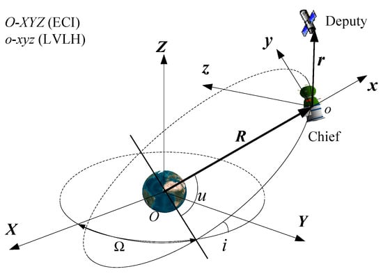
Figure 1.
Illustration of ECI and LVLH frames.
As the LVLH frame is attached to the chief’s mass centroid, the chief’s absolute state () should be known in order to sequentially estimate the deputy’s relative state, where represents the absolute position vector and represents the absolute velocity vector. In the ECI frame, the chief’s absolute motion can be described using the following dynamic model []:
where μ is the central body’s gravitational constant, , denotes the Euclidean norm of a vector, is the sum of acceleration, and is the perturbation acceleration. In this paper, only J2-perturbation is considered in because the dynamics of the non-conservative forces are not modeled accurately enough, and the associated analytical solutions cannot be accurately obtained. is the thrust acceleration vector, which is not considered in this study.
The six-dimensional state is used to denote the deputy’s real relative state to the chief in the chief’s LVLH frame, where represents the relative position vector and represents the relative velocity vector. The real relative state , which can also be denoted as , contains an error and remains to be estimated. A vector named nominal relative state is given and represent a known reference orbit without error, whose expectation satisfies . The difference between and is the estimation error , which is regarded as a random realization of the deputy’s relative state uncertainty. can be expressed as follows:
The relative orbital dynamics can be derived by differentiating the deputy’s and chief’s absolute orbital dynamics of Equation (3). Considering the central body’s J2-perturbation only, the relative motion of the deputy satisfies the following equations []:
where and are the chief’s angular velocity and angular acceleration, respectively, is the J2-perturbation described in the chief’s LVLH frame. Because of the non-linearized central field force, the equations in Equation (5) are nonlinear, which means they are fundamentally different from linear equations such as the C-W equation [] and the T-H equation []. It is worth notice that the model of Equation (5) applies equally to both and .
For a given initial condition , the solution of Equation (5) can be implicitly written as
Considering that there is an initial relative state error , by applying the order Taylor series expansion to Equation (6), the deviation of the current relative state from a nominal trajectory can be represented as follows:
where the second summation with the superscript is over all permutation of with by using the Einstein summation convention, is the maximum Taylor expansion order, and are the STTs from to . After the STTs are computed along the nominal trajectory, a random realization of the current relative state deviation can be computed as an analytic function of the random initial relative state error . However, the STTs has no analytical solution unless some approximations are assumed.
Specifically, Yang et al. [] developed a second-order analytic solution for Equation (5) by using a geometric method. The core dynamics of this solution consist of a second-order state transition of the mean relative orbital elements (ROEs) that includes the secular effects of J2 perturbation and a second-order transformation from the osculating ROE to the rectilinear relative state . With the help of a first-order transformation from mean ROE to osculating ROE that is derived by Gim and Alfriend [], the second-order analytical propagation of the time-dependent rectilinear relative state under J2 perturbation was formulated by Yang et al. [], which can be expressed as follows:
where denotes the Kronecker product, denotes the element of state vector , and the summation with the superscript is over all permutation of . The state transition tensors and can be calculated using the chief’s quasi-nonsingular elements or equivalently using its absolute state in the ECI frame; their expressions are presented in [].
In order to nonlinearly propagate the satellite’s relative state uncertainty, we need to obtain a nonlinear mapping of the relative state error . Equation (8) gives an analytic, second-order state transition of relative state in J2-perturbed, elliptic orbits. By linearizing the relative motion and considering the first-order term only in Equation (8), i.e., , it can be easily observed that the propagation of relative state is consistent with the propagation of relative state error , i.e., , as it satisfies . However, for a nonlinear relative motion such as Equation (8), the first-order state transition matrix (STM) for propagating the relative state deviation will be different from the STM for propagating the relative state , and the specific derivation process is shown below.
According to Equation (4), it satisfies at , and substituting this equation into Equation (8), we obtain
where , , and . Comparing Equation (9) with the propagation of using Equation (8), the propagation of the relative state error can be expressed as
where and are the STTs for propagating the relative state error [].
Comparing Equation (10) with the second-order solution in Equation (8), the propagation of relative state error depends on both the relative state error and the nominal relative state , and a correction on the first-order STT is required to propagate the relative state error when the second-order term is considered.
The analytic relative motion equations of Equations (8) and (10) are the second-order approximation solutions to the relative orbit dynamics, which will be employed to construct a second-order sequential filter in Section 3 by substituting Equations (8) and (10) into Equation (1).
2.3. Angle Measurements
As shown in Figure 2, the available measurements are bearing angles, here denoted as the azimuth, , and elevation, . In order to simplify the problem of relative orbit estimation, the measurement coordinates of the optical camera are set to coincide with the chief’s LVLH orbital coordinates. Therefore, the nonlinear measurement model that expresses the bearing angles as functions of the relative camera frame position is given as
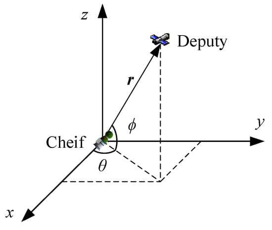
Figure 2.
Angle measurements in the chief LVLH frame.
Similarly to Equation (7), assuming that there is a relative state error existing on the nominal relative state , i.e., , by applying the order Taylor series expansion on Equation (11), the real angle measurements can be expressed as
where , denotes the element of vector , and the second summation with the superscript is the overall permutation of with , and are the STTs transforming the relative state to the angle measurements.
Truncating Equation (12) to the second order, the real angle measurements and their errors satisfy
where are the nominal measurements corresponding to the nominal relative state , and and are the STTs of the measurement equation.
For a linear approximation of the measurement equation, the Jacobian matrix can be expressed as
where the elements of satisfy the following equations []:
When the second-order nonlinear term is added, the non-zero elements of can be derived as
where [].
Note that Equation (13) denotes that the measurement function is evaluated at time , as a function of the solution flow . Substituting Equation (10) into Equation (13), a direct solution flow from to can be obtained as
The computation of STTs and can be given as
where and .
Equation (15) is the second-order analytic solution of angle measurements, which transforms the relative state error at time to the measurement errors at time . It can be used to construct a second-order sequential filter in Section 3 by substituting Equation (15) into Equation (1).
3. Nonlinear Sequential Filter Design
For estimation problems, the linear Kalman filter is probably the most well-known filtering technique; however, it can only be used for linear systems and, in general, cannot be used for trajectory estimation. In conventional spacecraft trajectory estimation, the extended Kalman filter (EKF) is usually implemented.
3.1. Extended Kalman Filter
The EKF, which is based on the Kalman filter algorithm, implicitly assumes that the real trajectory is within the boundary where the linear approximation about a reference trajectory can sufficiently model the trajectory dynamics and its statistics. Under this assumption, the mean trajectory is propagated according to the deterministic solution flow, the covariance matrix is linearly mapped assuming Gaussian statistics, and the deviation of the real trajectory from the best estimate is a zero-mean Gaussian process, which can be well-represented by the covariance centered on the best estimate. The EKF has mainly two steps: predict and update, they are presented as follows.
3.1.1. Prediction Equations of EKF
First, given an initial relative state and its associated uncertainty, which is usually described by a mean vector and a covariance matrix under Gaussian distribution. Here is the specific process of initialization:
where is the expectation operator, is the estimated mean trajectory at time , is the mean vector of initial error, and is the initial covariance matrix. In general, , which leads to . And the value of is set by users. For the filtering algorithm, the calculation can be performed when the initial value is known.
Second, propagate the mean and covariance matrix through the dynamics, and compute the estimated measurements.
where , and is the maximal number of iterations, which is determined by the precision required for the result. at time satisfies . is the measurement function evaluated at as a function of .
3.1.2. Update Equations of EKF
First, compute the Kalman gain as follows:
Second, update the mean and covariance:
It is worth notice that both and are used in Equation (20). The reason is that needs to be iteratively corrected with the difference of , so that the overall deviations of the final simulation results from the real measurements can be minimized.
3.2. Analytic Second-Order Extended Kalman Filter
Based on Equations (8)–(10), the local relative trajectory motion can be mapped analytically over the time interval while incorporating the second-order nonlinear effects, and the same analogy applies when mapping the trajectory statistics. The mean and covariance matrix of the relative dynamics at can be mapped analytically to as functions of the probability distribution at based on Equation (10) and a covariance analysis technique.
Following the EKF algorithm, the ASEKF algorithm is presented as follows.
3.2.1. Prediction Equations of ASEKF
First, the process of initialization is consistent with Equation (17). Calculations of variables of interest are given as
where . According to Equations (21)–(23), even if the relative state at time is Gaussian, the mapped trajectory distribution is no longer Gaussian due to system nonlinearity, and, hence, exact computation requires the computation of the higher-order moments. As shown in Equations (21)–(23), the highest order required for the computation in this study is fourth order, , and the different original moments can be computed using methods in [].
Let be the real relative trajectory to be estimated for ASEKF, and the second-order prediction equations are
where denotes that the measurement function is evaluated at as a function of the solution flow .
3.2.2. Update Equations of ASEKF
The second-order update equations are
Then, the posteriori mean vector and covariance can be given as
The full flow of the ASEKF is summarized in a compact form as Algorithm 1:
| Algorithm 1: Analytical Second-Order Extended Kalman Filter | ||
| Input: initial mean relative state , covariance matrix | ||
| Output: final mean relative state and covariance matrix | ||
| 1. | for do | |
| 2. | Calculate and according to Equation (29) from Ref. []; | |
| 3. | Calculate and according to equations of their elements after Equation (14); | |
| 4. | Calculate , and according to Equations (21)–(23) in this paper; | |
| 5. | Calculate , and according to Equations (24)–(26) in this paper; | |
| 6. | Calculate and according to Equations (27) and (28) in this paper; | |
| 7. | Calculate , and according to Equation (29) in this paper | |
| 8. | end for | |
| 9. | return and | |
When the real trajectory is within the convergence radius of the reference trajectory, we shall see later that the ASEKF can provide a more accurate solution and faster convergence than the EKF.
4. Simulation Results
To illustrate the effectiveness of the proposed ASEKF algorithm based on the second-order analytic relative orbital motion equation, two conditions were considered: (1) the perfect observation condition, which means that the target spacecraft could be observed throughout the whole simulation process; (2) the imperfect observation condition, which means that the observation condition is limited and there exist unobservable periods. The orbital elements of the observing spacecraft used in the simulations are listed in Table 1.

Table 1.
The Initial orbital elements of observing spacecraft.
Assuming that only the angle information can be obtained by the spacecraft. The standard deviations of measurement noise are set as , and the measurement noise covariance matrix is set as . In the same vein, the standard deviations of process noise are set as and , while the covariance of the process noise is set as . The filters are initialized as , and the sampling step is 10 s. Finally, the performance of the proposed algorithm is compared with EKF based on the first-order linear relative-motion equation.
4.1. Relative Orbit Determination with Perfect Measurement
This condition is divided into different cases. In Case 1, the initial relative state of the target spacecraft is set as , , which means the initial distance between the chief and deputy is 55,000 m apart. In Case 2, the initial distance is set as 25,000 m, which leads to , .
4.1.1. Result of Case 1
Figure 3, Figure 4 and Figure 5 show the filtering performance of EKF and ASEKF in Case 1. The left-side column in Figure 3 represents the position error in three components, while the right-side column represents the velocity error. The error is evaluated as the difference between the estimated state and the real state. Figure 3 shows the filtering performance of the EKF algorithm, as shown after a continuous observation of about 0.5 h, the estimated uncertainty beyond the scale depicted (shown with values). Figure 4 shows the filtering performance of the ASEKF algorithm. During the entire simulation process, the estimated value is always within the range depicted by the estimated covariance. The results of Monte Carlo analysis with 100 runs demonstrated that the ASEKF algorithm proposed in this study has better performance as compared to the linear estimator, and it can be noted that the predicted covariance (blue dashed line) of ASEKF provides good agreement with the sample trajectories of Monte Carlo simulation. Moreover, Figure 5 shows the RMS position and velocity simulation errors of EKF and ASEKF algorithms with 100 Monte Carlo runs, which shows that the RMS position and velocity errors of the ASEKF algorithm are much smaller than those of the EKF algorithm.
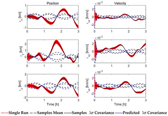
Figure 3.
Simulation results of EKF with perfect measurement (100 Monte Carlo runs).
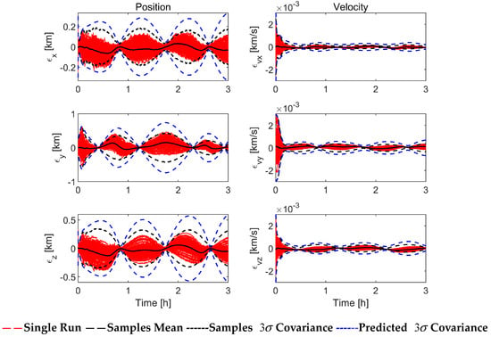
Figure 4.
Simulation results of ASEKF with perfect measurement (100 Monte Carlo runs).
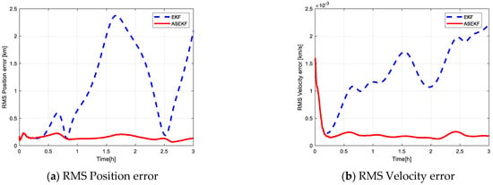
Figure 5.
Comparison of state estimation accuracy with perfect measurement (100 Monte Carlo runs).
4.1.2. Result of Case 2
Figure 6, Figure 7 and Figure 8 show the filtering performance of EKF and ASEKF in Case 2. Referring to Figure 6 and Figure 7, the performances of EKF and ASEKF are basically the same because the estimated value is always within the range depicted by the estimated covariance during the whole simulation process. As for the RMS errors with 100 Monte Carlo runs in Figure 8, although EKF also performs well, ASEKF still holds a slight advantage.
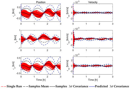
Figure 6.
Simulation results of EKF with perfect measurement (100 Monte Carlo runs).
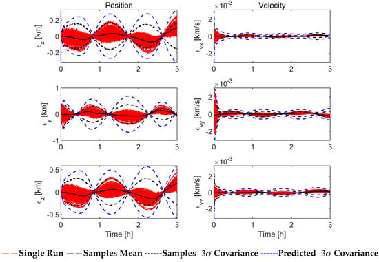
Figure 7.
Simulation results of ASEKF with perfect measurement (100 Monte Carlo runs).
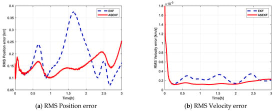
Figure 8.
Comparison of state estimation accuracy with perfect measurement (100 Monte Carlo runs).
Comparing Case 1 with Case 2, the advantage of ASEKF is more obvious when the initial relative position is further. It also shows that ASEKF provides superior robustness. In fact, the main scope of application of ASEKF is the case where the initial relative distance is 50,000 m or more. As a result, the EKF performs too poorly in Case 1 because it is not sufficient for such a working condition where the initial relative distance is far away, which is an important reason for the development of ASEKF.
4.2. Relative Orbit Determination with Imperfect Measurement
This condition is also divided into two different cases named Case 3 and Case 4, which are both based on Case 2. The initial distance is set as 25,000 m, and the half cone angle of the onboard camera is limited to 60° so that there exist unobservable periods. The difference between Case 3 and Case 4 is the visible period of the target satellite. The former has observation information in the initial stage of simulation, while the latter is located outside the field of view at first.
4.2.1. Result of Case 3
Figure 9 shows the visible period of the observing satellite to the target satellite during the simulation, in which the value “1” represents observable while “0” represents unobservable. Figure 10, Figure 11 and Figure 12 show the filtering performance of EKF and ASEKF under imperfect observations. In the initial stage of simulation, both EKF and ASEKF algorithms perform well until there is no input of observation information. Large estimation errors start to appear and increase as the target spacecraft is located outside the field of view. However, the ASEKF rapidly converges once the measurement is available before 1.5 h, which indicates good tracking capability. In contrast, EKF performs poorly.

Figure 9.
Visible period of the target satellite.
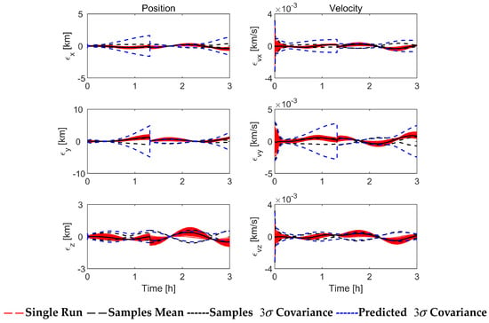
Figure 10.
Simulation results of EKF with imperfect measurement (100 Monte Carlo runs).
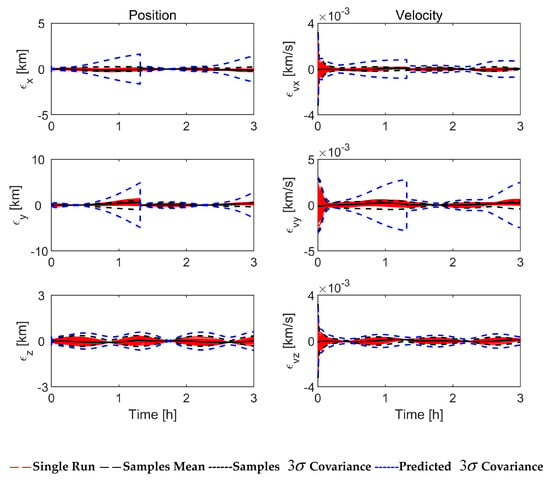
Figure 11.
Simulation results of ASEKF with imperfect measurement (100 Monte Carlo runs).
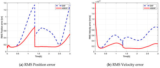
Figure 12.
Comparison of state estimation accuracy with imperfect measurement (100 Monte Carlo runs).
4.2.2. Result of Case 4
Similarly to Case 3, Figure 13 shows the visible period of the observing satellite to the target spacecraft under imperfect observations. Figure 14, Figure 15 and Figure 16 show the filtering performance of EKF and ASEKF in Case 4. Within the first half hour of the simulation, both EKF and ASEKF algorithms have large estimation errors due to the loss of observation information. EKF still maintains the divergence even with new measurement information. On the contrary, the ASEKF rapidly converges once the measurement is available, which indicates its relatively low dependence on observation.

Figure 13.
Visible period of the target satellite.
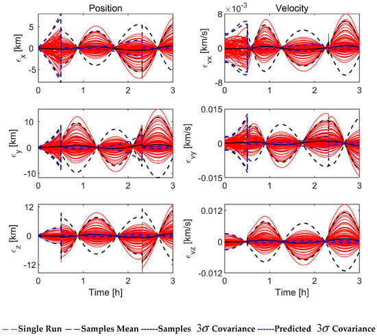
Figure 14.
Simulation results of EKF with imperfect measurement (100 Monte Carlo runs).
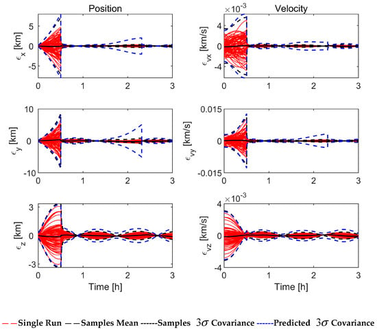
Figure 15.
Simulation results of ASEKF with imperfect measurement (100 Monte Carlo runs).
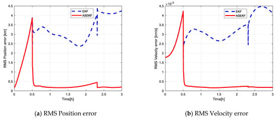
Figure 16.
Comparison of state estimation accuracy with imperfect measurement (100 Monte Carlo runs).
Comparing Case 3 with Case 2, the advantage of ASEKF is more obvious than EKF when there exist unobservable periods. It is shown that ASEKF is relatively less dependent on information and has higher robustness. According to Case 4, ASEKF still performs brilliantly even when observations are started after many rounds of iterations. In actual space missions, unobservable situations frequently occur, which is another important reason for the proposal of ASEKF.
5. Conclusions
Although several higher-order extended Kalman filters have been studied for state estimation of nonlinear dynamical systems, numerical integrations are required to compute the higher-order state transition tensors (STTs), which imposes a heavy computational burden. In this study, an analytical second-order extended Kalman filter (ASEKF) is proposed for satellite relative orbit estimation with space-based angles-only measurements. First, the analytic STTs that truncated to the second-order nonlinear terms of the J2-perturbed relative orbit dynamics are introduced, which is used to analytically propagate the state mean and covariance in the prediction step of ASEKF. Second, a second-order nonlinear mapping from relative state to angles-only measurements is derived, which is used to analytically transform the predicted state mean and covariance in the update step of ASEKF. Finally, the ASEKF is formulated to sequentially estimate the relative states of the satellites and their associated uncertainties. Numerical results show that the proposed ASEKF algorithm provides superior robustness and mean-square error performance compared to linear estimators under the conditions considered.
It also should be noted that the premise of this work is the second-order analytical equation of , then STTs and measurement equations could be used to complete the calculation of ASEKF. As for some simple aerodynamics, for example, the dynamical models used to fit the atmospheric drag are not precise enough at this stage, especially the complex change rule of the atmospheric density in the low orbit. The related analysis is usually approximated using numerical solutions, which leads to the fact that the second-order analytic solution of the atmospheric drag perturbation is unknown, and only the J2-perturbation is considered in this study. Therefore, in subsequent research, the influence of other parts of perturbation acceleration should be considered.
Author Contributions
Conceptualization, Z.Y.; methodology, Z.Y. and M.S.; software, Z.Y., M.S. and J.Y.; validation, M.S. and J.Y.; formal analysis, M.S. and J.Y.; investigation, M.S.; resources, Z.Y. and M.S.; data curation, M.S.; writing—original draft preparation, Z.Y. and M.S.; writing—review and editing, M.S.; visualization, M.S.; supervision, Z.Y.; project administration, Z.Y.; funding acquisition, Z.Y. All authors have read and agreed to the published version of the manuscript.
Funding
This work was supported by the National Natural Science Foundation of China (12372052, 12125207); the Young Elite Scientists Sponsorship Program (2021-JCJQ-QT-047); and the Natural Science Foundation of Hunan Province (2023JJ20047). This article is a revised and expanded version of a paper entitled (Second-Order Analytic Extended Kalman Filter for Angles-Only Relative Orbit Navigation), which was presented at the 8th International Conference on Vibration Engineering, Shanghai, 24–26 July 2021.
Data Availability Statement
The data presented in this study are available on request from the corresponding author.
Conflicts of Interest
The authors declare no conflict of interest.
Abbreviations
| IROD | Initial relative orbit determination |
| ROE | Relative orbital element |
| EKF | Extended Kalman filter |
| MRD-DCSCKF | multiple-step, randomly delayed, dynamic-covariance-scaling cubature Kalman filter |
| CEKF | Consensus extended Kalman filter |
| UKF | Unscented Kalman filter |
| SRUKF | Square-root unscented Kalman filter |
| HEKF | High-order extended Kalman filter |
| DA | Differential algebra |
| KOF | Koopman Operator filter |
| STTs | State transition tensors |
| ASEKF | Analytical second-order extended Kalman filter |
| ECI | Earth-centered inertial |
| LVLH | Local vertical, local horizontal |
| STM | State transition matrix |
References
- Aldrin, B.E. Line-of-Sight Guidance Techniques for Manned Orbital Rendezvous. Ph.D. Thesis, Massachusetts Institute of Technology, Cambridge, MA, USA, 1963. [Google Scholar]
- D’Amico, S.; Ardaens, J.-S.; Gaias, G.; Benninghoff, H.; Schlepp, B.; Jørgensen, J.L. Noncooperative rendezvous using angles-only optical navigation: System design and flight results. J. Guid. Control. Dyn. 2013, 36, 1576–1595. [Google Scholar] [CrossRef]
- Gaias, G.; Ardaens, J.-S.; D’Amico, S. The autonomous vision approach navigation and target identification (AVANTI) experiment: Objectives and design. In Proceedings of the GNC 2014 9th International ESA Conference on Guidance, Navigation and Control Systems, Porto, Portugal, 2–6 June 2014. [Google Scholar]
- Sellmaier, F.; Boge, T.; Spurmann, J.; Gully, S.; Rupp, T.; Huber, F. On-Orbit Servicing Missions: Challenges and Solutions for Spacecraft Operations. In Proceedings of the AIAA, Orlando, FL, USA, 4–7 January 2010; pp. 2010–2159. [Google Scholar]
- Alfriend, K.T.; Vadali, S.R.; Gurfil, P.; How, J.P.; Breger, L. Spacecraft Formation Flying: Dynamics, Control and Navigation; Butterworth-Heinemann: Oxford, UK, 2010. [Google Scholar]
- Woffinden, D.C.; Geller, D.K. Observability Criteria for Angles-Only Navigation. IEEE Trans. Aerosp. Electron. Syst. 2009, 45, 1194–1208. [Google Scholar] [CrossRef]
- Schmidt, J.; Geller, D.; Chavez, F.R. Viability of Angles-only Navigation for Orbital Rendezvous Operation. In Proceedings of the AIAA Guidance, Navigation, and Control Conference, Toronto, ON, Canada, 2–5 August 2010. [Google Scholar]
- Newman, B.; Lovell, A.; Pratt, E. Second Order Nonlinear Initial Orbit Determination for Relative Motion Using Volterra Theory. Adv. Astronaut. Sci. 2014, 152, 1253–1272. [Google Scholar]
- Gaias, G.; D’Amico, S.; Ardaens, J.S. Angles-Only navigation to a noncooperative satellite using relative orbital elements. J. Guid. Control. Dyn. 2014, 37, 439–451. [Google Scholar] [CrossRef][Green Version]
- Du, R.; Zhang, X.; Liao, W. Fast initial relative orbit determination method of angles-only relative navigation. Syst. Eng. Electron. 2021, 43, 1057–1068. [Google Scholar]
- Willis, M.; D’Amico, S. Fast Angles-Only Relative Navigation Using Polynomial Dynamics. Adv. Space Res. 2023, 73, 5484–5500. [Google Scholar] [CrossRef]
- Geller, D.K.; Klein, I. Angles-only navigation state observability during orbital proximity operations. J. Guid. Control. Dyn. 2014, 37, 1976–1983. [Google Scholar] [CrossRef]
- LeGrand, K.A.; DeMars, K.J.; Pernicka, H.J. Bearings-only initial relative orbit determination. J. Guid. Control. Dyn. 2015, 38, 1699–1713. [Google Scholar] [CrossRef]
- Gong, B.; Wang, S.; Li, S.; Li, X. Review of space relative navigation based on angles-only measurements. Astrodynamics 2023, 7, 131–152. [Google Scholar] [CrossRef]
- Gong, B.; Li, S.; Zheng, L.; Feng, J. Analytic Initial Relative Orbit Solution for Angles-Only Space Rendezvous Using Hybrid Dynamics Method. Comput. Model. Eng. Sci. 2020, 122, 221–234. [Google Scholar] [CrossRef]
- Dai, C.; Qiang, H.; Zhang, D.; Hu, S.; Gong, B. Relative Orbit Determination Algorithm of Space Targets with Passive Observation. J. Syst. Eng. Electron. 2024, 35, 793–804. [Google Scholar] [CrossRef]
- Clohessy, W.H.; Wiltshire, R.S. Terminal guidance system for satellite rendezvous. J. Aerosp. Sci. 1960, 27, 653–658. [Google Scholar] [CrossRef]
- Tschauner, J.; Hempel, P. Rendezvous zu einem in elliptischer bahn umlaufenden ziel. Astronaut. Acta 1965, 11, 312–321. [Google Scholar]
- Gim, D.W.; Alfriend, K.T. State transition matrix of relative motion for the perturbed noncircular reference orbit. J. Guid. Control. Dyn. 2003, 26, 956–971. [Google Scholar] [CrossRef]
- Gelb, A. Applied Optimal Estimation; MIT Press: Cambridge, MA, USA, 1974. [Google Scholar]
- Chang, L.; Liu, J.; Chen, Z.; Bai, J.; Shu, L. Stereo Vision-Based Relative Position and Attitude Estimation of Non-Cooperative Spacecraft. Aerospace 2021, 8, 230. [Google Scholar] [CrossRef]
- Mu, R.; Chu, Y.; Zhang, H.; Liang, H. A Multiple-Step, Randomly Delayed, Robust Cubature Kalman Filter for Spacecraft-Relative Navigation. Aerospace 2023, 10, 289. [Google Scholar] [CrossRef]
- Wang, J.; Butcher, E.A.; Tansel, Y. Space-based relative orbit estimation using information sharing and the consensus Kalman filter. J. Guid. Control. Dyn. 2019, 42, 491–507. [Google Scholar] [CrossRef]
- Junkins, J.; Singla, P. How Nonlinear Is It? A Tutorial on Nonlinearity of Orbit and Attitude Dynamics. J. Astronaut. Sci. 2004, 52, 7–60. [Google Scholar] [CrossRef]
- Julier, S.J.; Uhlmann, J.K. Unscented Filtering and Nonlinear Estimation. Proc. IEEE 2004, 92, 401–422. [Google Scholar] [CrossRef]
- Du, R.; Liao, W.; Zhang, X. Feasibility analysis of angles-only navigation algorithm with multisensor data fusion for spacecraft noncooperative rendezvous. Astrodynamics 2023, 7, 179–196. [Google Scholar] [CrossRef]
- Park, R.S.; Scheeres, D.J. Nonlinear Semi Analytic Methods for Trajectory Estimation. J. Guid. Control. Dyn. 2007, 30, 1668–1676. [Google Scholar] [CrossRef]
- Majji, M.; Junkins, J.; Turner, J. A High Order Method for Estimation of Dynamic Systems. J. Astronaut. Sci. 2008, 56, 401–440. [Google Scholar] [CrossRef]
- Cavenago, F.; Di Lizia, P.; Massari, M.; Wittig, A. On-board spacecraft relative pose estimation with high-order extended Kalman filter. Astronaut. Acta 2019, 158, 55–67. [Google Scholar] [CrossRef]
- Servadio, S.; Cavenago, F.; Di Lizia, P.; Massari, M. Nonlinear Prediction in Marker-Based Spacecraft Pose Estimation with Polynomial Transition Maps. J. Spacecr. Rocket. 2022, 59, 511–523. [Google Scholar] [CrossRef]
- Servadio, S.; Zanetti, R. Recursive Polynomial Minimum Mean-Square Error Estimation with Applications to Orbit Determination. J. Guid. Control. Dyn. 2020, 43, 939–954. [Google Scholar] [CrossRef]
- Servadio, S.; Parker, W.; Linares, R. Uncertainty Propagation and Filtering via the Koopman Operator in Astrodynamics. J. Spacecr. Rocket. 2023, 60, 1639–1655. [Google Scholar] [CrossRef]
- Yang, Z.; Luo, Y.; Zhang, J. Second-order Analytical Solution of Relative Motion in J2-Perturbed Elliptic Orbits. J. Guid. Control. Dyn. 2018, 41, 2257–2269. [Google Scholar] [CrossRef]
- Yang, Z.; Luo, Y.; Zhang, J.; Li, H. Nonlinear Analytic Solution for Perturbed Relative Motion Using Differential Equinoctial Elements. Celest. Mech. Dyn. Astron. 2018, 130, 1–33. [Google Scholar] [CrossRef]
- Vallado, D.A. Fundamentals of Astrodynamics and Applications, 3rd ed.; Microcosm Press: Portland, OR, USA, 2007. [Google Scholar]
- Sullivan, J.; Grimberg, S.; D’Amico, S. Comprehensive Survey and Assessment of Spacecraft Relative Motion Dynamics Models. J. Guid. Control. Dyn. 2017, 40, 1837–1859. [Google Scholar] [CrossRef]
- Yang, Z.; Yin, J.; Shu, P.; Luo, Y. Second-Order Analytic Extended Kalman Filter for Angles-Only Relative Orbit Navigation. In Proceedings of the 8th International Conference on Vibration Engineering, Shanghai, China, 24–26 July 2021. [Google Scholar]
- Yang, Z.; Luo, Y.; Lappas, V.; Tsourdos, A. Nonlinear Analytical Uncertainty Propagation for Relative Motion near J2-Perturbed Elliptic Orbits. J. Guid. Control. Dyn. 2018, 41, 888–903. [Google Scholar] [CrossRef]
Disclaimer/Publisher’s Note: The statements, opinions and data contained in all publications are solely those of the individual author(s) and contributor(s) and not of MDPI and/or the editor(s). MDPI and/or the editor(s) disclaim responsibility for any injury to people or property resulting from any ideas, methods, instructions or products referred to in the content. |
© 2024 by the authors. Licensee MDPI, Basel, Switzerland. This article is an open access article distributed under the terms and conditions of the Creative Commons Attribution (CC BY) license (https://creativecommons.org/licenses/by/4.0/).