
Switching Logic for a Direct Hybrid Electric Powertrain


Abstract
1. Introduction
2. Materials and Methods
2.1. Direct Hybrid Powertrain of a Fuel Cell and a Battery
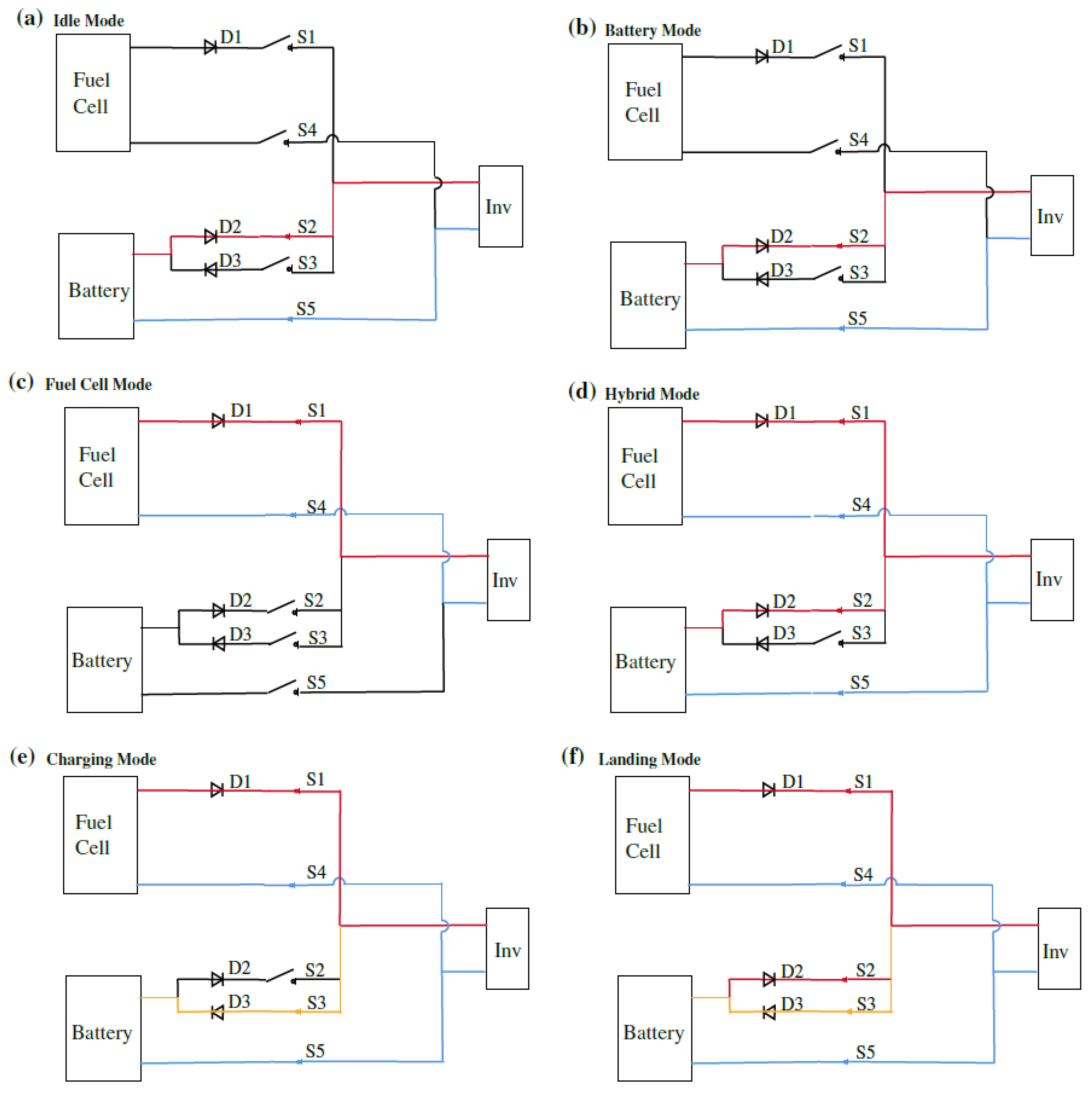
- In Idle Mode, all switches are open (Figure 4a). This is the situation before starting the system. In this mode, all sub-systems, the 24 V supplies of the components, the communication and the cooling of the system can be checked and tested before starting up.
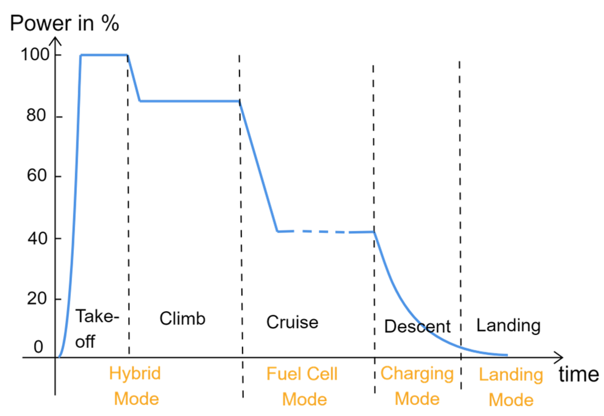
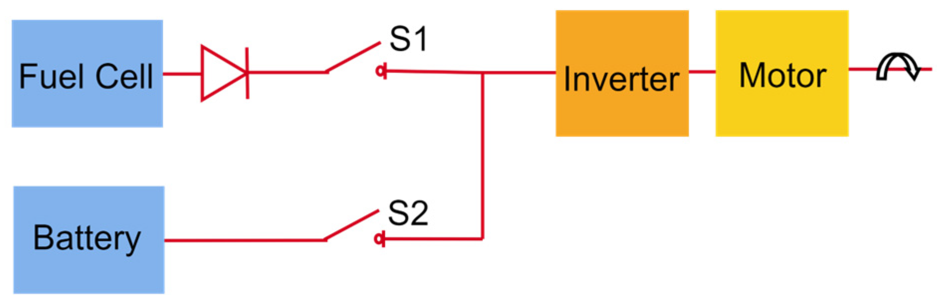
- Fuel Cell Mode is the mode that is used for the longest duration during a flight. For a correctly dimensioned fuel cell, this mode delivers the required power during the cruise phase. The power flow in Fuel Cell Mode is shown in Figure 4c and it can be seen that switches S1 on the positive path (red line) and S4 on the negative path (blue line) are closed [14].
- Hybrid Mode is the mode of choice for take-off and climb phases that require the most power. If the power required by the motor for propulsion exceeds the power output of the fuel cell, the battery can provide additional power for a certain period of time. In Hybrid Mode, switches S1 and S2 on the positive path (red line) and S4 and S5 on the negative path (blue line) are closed [14], enabling a power flow as shown in Figure 4d.
- Battery Mode is not meant to occur during normal operation. It is, however, exclusively dedicated for emergencies situations. In case the fuel cell fails, the battery can supply power on its own for a certain period of time. In this mode, only the battery is connected to the inverter via switches S2 in the positive path (red line) and S4 in the negative path (blue line). The resulting power flow in Battery Mode is shown in Figure 4b.
- Charging Mode can be used in the descent phase, when the fuel cell can provide more power than the motor requires. This additional power can be used to charge the battery if the DC bus voltage generated by the fuel cell is higher than the battery voltage and the battery is not already fully charged (SOC < 100%). The charging path from the fuel cell is shown as a red and yellow line in Figure 4e. In Charging Mode, switches S1 and S4 are closed and current can flow from the fuel cell to the battery by switch S3.
- Landing Mode is required during approach and landing. To enable a go-around in case of an aborted landing attempt, the fuel cell as well as the battery have to be connected. At the same time, energy that is recuperated from the motor/generator has to be able to flow into the battery. Therefore, all switches (S1 to S5) are closed in this mode.
2.2. Mode Transitions in a Direct Hybrid Powertrain
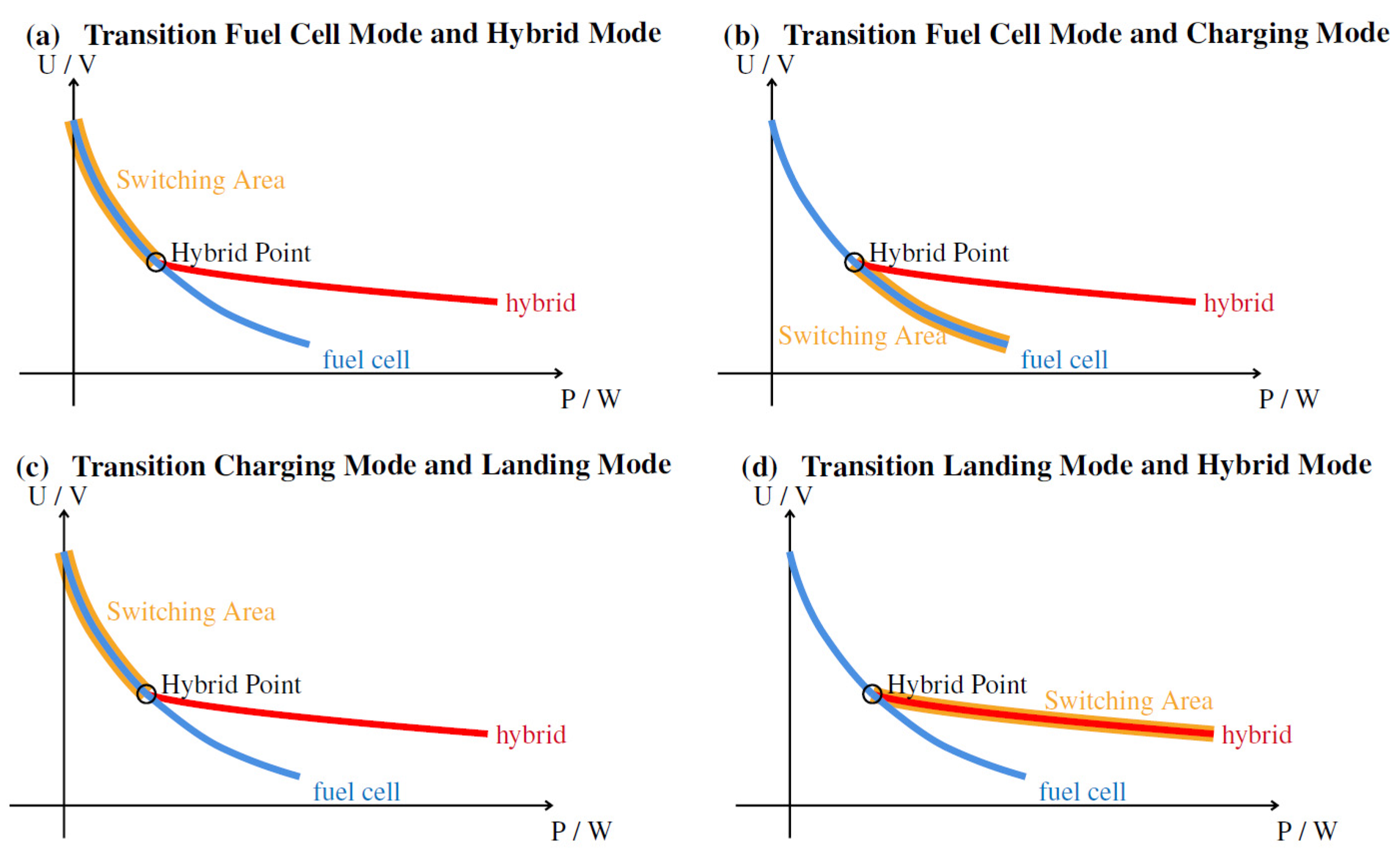
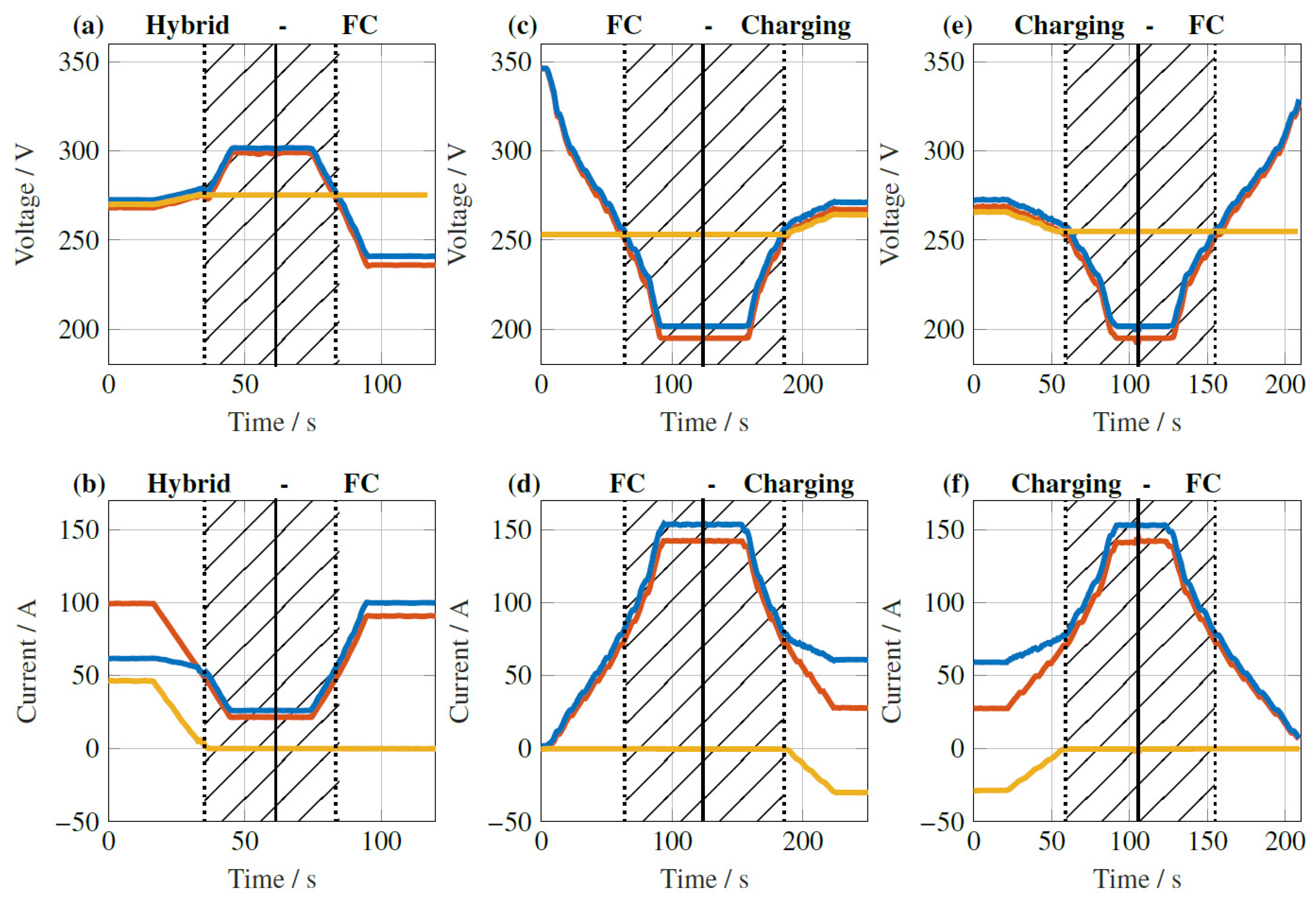
2.2.1. Switching between Fuel Cell Mode and Hybrid Mode
2.2.2. Switching between Fuel Cell Mode and Charging Mode
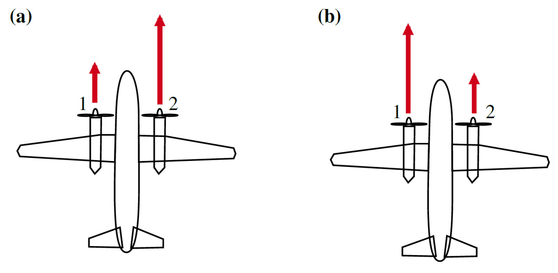
2.2.3. Switching into Landing Mode
3. Results and Discussion
3.1. Experimental Verification
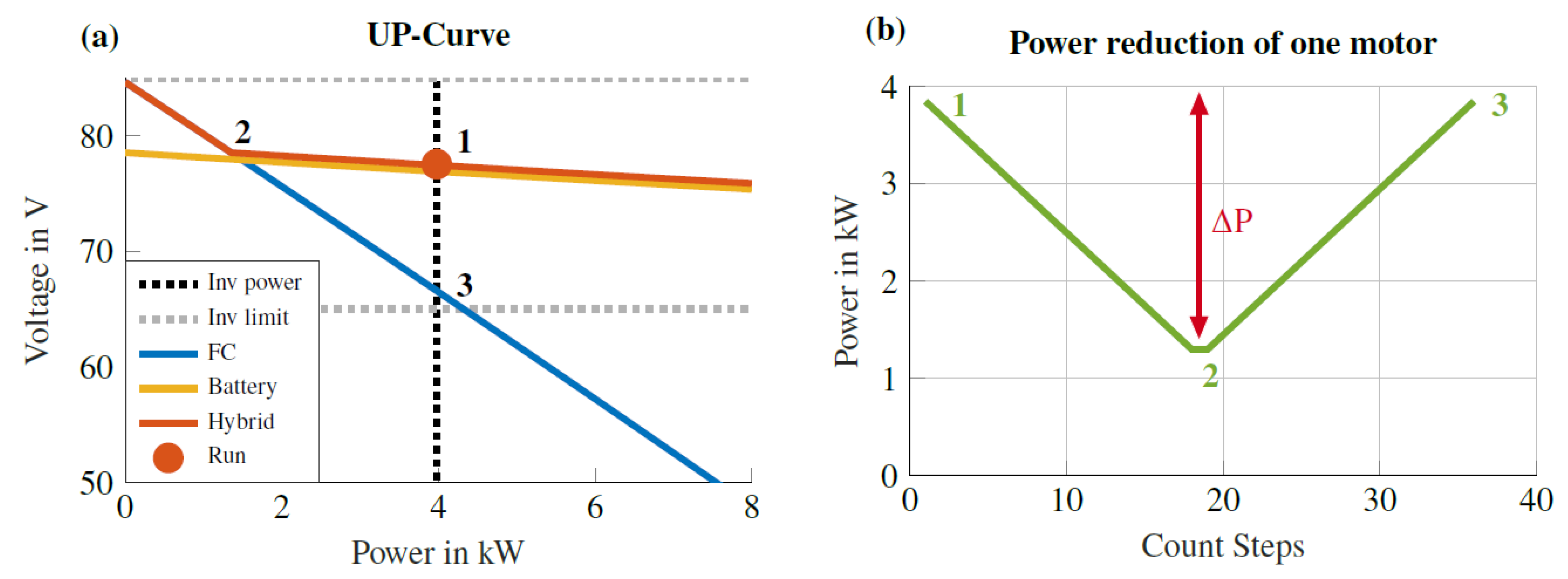
3.2. Power Reduction during Switching
4. Conclusions
Author Contributions
Funding
Data Availability Statement
Conflicts of Interest
Abbreviations
| DC | Direct current |
| Inv | Inverter |
| IBat | Current of a battery in A |
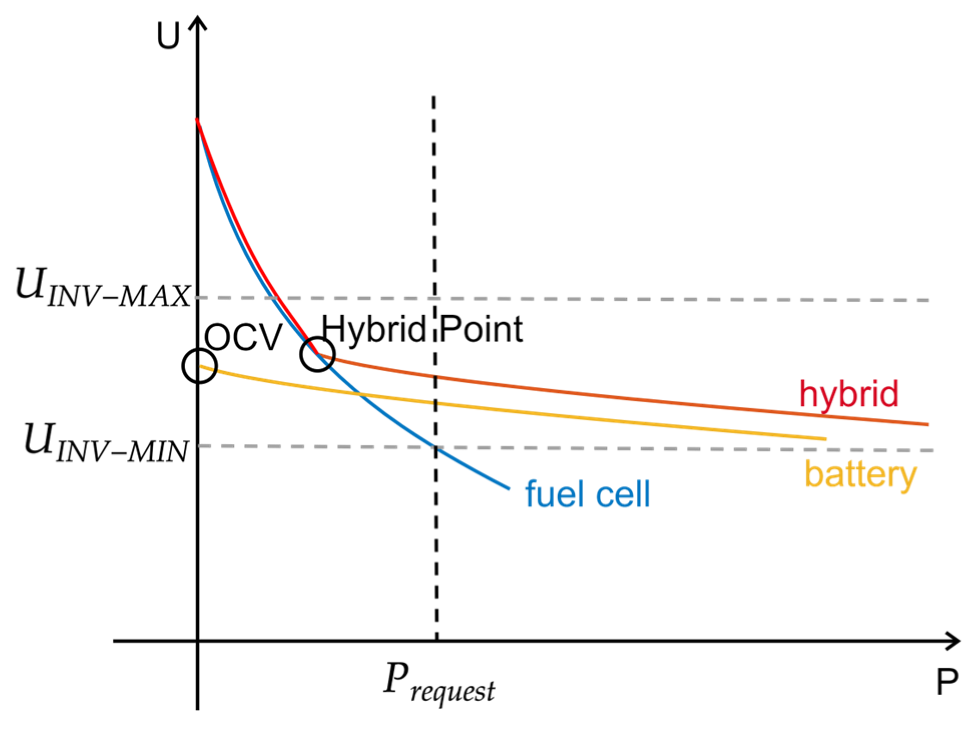
| OCV | Open circuit voltage |
| PMS | Power management system |
| P | Power in W |
| PEM | Polymer electrolyte membrane |
| Prequest | Power demand of the propulsion system in W |
| SOC | State of charge |
| Uinv_max | Max. voltage of the inverter in V |
| Uinv_min | Min. voltage of the inverter in V |
| VFC | Voltage of a fuel cell in V |
| VBat | Voltage of a battery in V |
References
- Gössling, S.; Humpe, A. The Global Scale, Distribution and Growth of Aviation: Implications for Climate Change. Glob. Environ. Chang. 2020, 65, 102194. [Google Scholar] [CrossRef] [PubMed]
- Ansell, P.J. Hydrogen-Electric Aircraft Technologies and Integration: Enabling an environmentally sustainable aviation future. IEEE Electrif. Mag. 2022, 10, 6–16. [Google Scholar] [CrossRef]
- Terrenoire, E.; Hauglustaine, D.A.; Gasser, T.; Penanhoat, O. The Contribution of Carbon Dioxide Emissions from the Aviation Sector to Future Climate Change. Environ. Res. Lett. 2019, 14, 084019. [Google Scholar] [CrossRef]
- Olsthoorn, X. Carbon Dioxide Emissions from International Aviation: 1950–2050. J. Air Transp. Manag. 2001, 7, 87–93. [Google Scholar] [CrossRef]
- Anger, A.; Köhler, J. Including aviation emissions in the EU ETS: Much ado about nothing? A review. Transp. Policy 2010, 17, 38–46. [Google Scholar] [CrossRef]
- Huete, J.; Nalianda, D.; Zaghari, B.; Pilidis, P. A Strategy to Decarbonize Civil Aviation: A Phased Innovation Approach to Hydrogen Technologies. IEEE Electrif. Mag. 2022, 10, 27–33. [Google Scholar] [CrossRef]
- Su-ungkavatin, P.; Tiruta-Barna, L.; Hamelin, L. Biofuels, electrofuels, electric or hydrogen?: A review of current and emerging sustainable aviation systems. Prog. Energy Combust. Sci. 2023, 96, 101073. [Google Scholar] [CrossRef]
- Gao, Y.; Jausseme, C.; Huang, Z.; Yang, T. Hydrogen-Powered Aircraft: Hydrogen–electric hybrid propulsion for aviation. IEEE Electrif. Mag. 2022, 10, 17–26. [Google Scholar] [CrossRef]
- Brinner, A.; Philipps, F. Hydrogen as the Fuel of the Future—Production; Purification; Storage. In Proceedings of the Conference Proceeding of Motor & Umwelt 2001, Graz, Austria, 6–7 September 2001. [Google Scholar]
- Møller, K.T.; Jensen, T.R.; Akiba, E.; Li, H.W. Hydrogen—A sustainable energy carrier. Prog. Nat. Sci. Mater. Int. 2017, 27, 34–40. [Google Scholar] [CrossRef]
- Massaro, M.C.; Biga, R.; Kolisnichenko, A.; Marocco, P.; Monteverde, A.H.A.; Santarelli, M. Potential and technical challenges of on-board hydrogen storage technologies coupled with fuel cell systems for aircraft electrification. J. Power Sources 2023, 555, 232397. [Google Scholar] [CrossRef]
- Burschyk, T.; Cabac, Y.; Silberhorn, D.; Boden, B.; Nagel, B. Liquid hydrogen storage design trades for a short-range aircraft concept. CEAS Aeronaut. J. 2023, 14, 879–893. [Google Scholar] [CrossRef]
- Schefer, H.; Fauth, L.; Kopp, T.H.; Mallwitz, R.; Friebe, J.; Kurrat, M. Discussion on Electric Power Supply Systems for All Electric Aircraft. IEEE Access 2020, 8, 84188–84216. [Google Scholar] [CrossRef]
- Hoenicke, P.; Ghosh, D.; Muhandes, A.; Bhattacharya, S.; Bauer, C.; Kallo, J.; Willich, C. Power Management Control and Delivery Module for a Hybrid Electric Aircraft using Fuel Cell and Battery. Energy Convers. Manag. 2021, 244, 114445. [Google Scholar] [CrossRef]
- Howroyd, S.; Chen, R. Powerpath Controller for Fuel Cell & Battery Hybridisation. Int. J. Hydrogen Energy 2016, 41, 4229–4238. [Google Scholar] [CrossRef]
- Ng, W.; Datta, A. Hydrogen fuel cells and batteries for electric-vertical takeoff and landing aircraft. J. Aircr. 2019, 56, 1765–1782. [Google Scholar] [CrossRef]
- Lapeña-Rey, N.; Mosquera, J.; Bataller, E.; Ortí, F. First fuel-cell manned aircraft. J. Aircr. 2010, 47, 1825–1835. [Google Scholar] [CrossRef]
- Benzaquen, J.; He, J.; Mirafzal, B. Toward more electric powertrains in aircraft: Technical challenges and advancements. CES Trans. Electr. Mach. Syst. 2021, 5, 177–193. [Google Scholar] [CrossRef]
- Bhattacharya, S.; Anagnostou, D.; Schwane, P.; Bauer, C.; Kallo, J.; Willich, C. A Flexible DC-DC Converter with Multi-Directional Power Flow Capabilities for Power Management and Delivery Module in a Hybrid Electric Aircraft. Energies 2022, 15, 5495. [Google Scholar] [CrossRef]
- Bataller-Planes, E.; Lapena-Rey, N.; Mosquera, J.; Ortí, F.; Oliver, J.Á.; GarcÍa, Ó.; Moreno, F.; Portilla, J.; Torroja, Y.; Vasic, M.; et al. Power Balance of a Hybrid Power Source in a Power Plant for a Small Propulsion Aircraft. IEEE Trans. Power Electron. 2009, 24, 2856–2866. [Google Scholar] [CrossRef]
- Nishizawa, A.; Kallo, J.; Garrot, O.; Weiss-Ungethüm, J. Fuel Cell and Li-ion Battery Direct Hybridization System for Aircraft Applications. J. Power Sources 2013, 222, 294–300. [Google Scholar] [CrossRef]
- Lu, B.; Sharma, S.K. A literature review of IGBT fault diagnostic and protection methods for power inverters. IEEE Trans. Ind. Appl. 2009, 45, 1770–1777. [Google Scholar] [CrossRef]
- Costa, L.F.; Liserre, M. Failure analysis of the DC-DC converter: A comprehensive survey of faults and solutions for improving reliability. IEEE Power Electron. Mag. 2018, 5, 42–51. [Google Scholar] [CrossRef]
- Ji, B.; Pickert, V.; Cao, W.; Zahawi, B. In situ diagnostics and prognostics of wire bonding faults in IGBT modules for electric vehicle drives. IEEE Trans. Power Electron. 2013, 28, 5568–5577. [Google Scholar] [CrossRef]
- Graf, T.; Fonk, R.; Schröter, J.; Hoenicke, P.; Bauer, C.; Kallo, J.; Willich, C. Investigation of a Fuel Cell Hybrid System with a new Modular Test Bench Approach for All Electric Hybrid Power Train Systems. J. Energy Storage 2022, 56, 105999. [Google Scholar] [CrossRef]
- Graf, T.; Fonk, R.; Paessler, S.; Bauer, C.; Kallo, J.; Willich, C. Low Pressure Influence on a Direct Fuel Cell Battery Hybrid System for Aviation. Int. J. Hydrogen Energy 2024, 50, 672–681. [Google Scholar] [CrossRef]
- Graf, T.; Fonk, R.; Bauer, C.; Willich, C. Dimensioning of a direct fuel cell battery hybrid system for an all-electric aircraft. In Proceedings of the AIAA AVIATION 2023 Forum, San Diego, CA, USA, 12–16 June 2023; p. 4536. [Google Scholar] [CrossRef]
- Kallo, J. DLR leads HY4 project for four-seater fuel cell aircraft. Fuel Cells Bull. 2015, 2015, 13. [Google Scholar] [CrossRef]
- Air Accidents Investigation Branch. AAIB Investigation to Piper PA-46-350P (Modified), G-HYZA - Propulsion System Failure and Forced Landing, One Mile North of Cranfield Airport, 29 April 2021. Available online: https://www.gov.uk/aaib-reports/aaib-investigation-to-piper-pa-46-350p-modified-g-hyza (accessed on 11 January 2024).
- Epstein, A.H.; O’Flarity, S.M. Considerations for reducing aviation’s CO2 with aircraft electric propulsion. J. Propuls. Power 2019, 35, 572–582. [Google Scholar] [CrossRef]
- Pratt, J.W.; Brouwer, J.; Samuelsen, G.S. Performance of Proton Exchange Membrane Fuel Cell at High-Altitude Conditions. J. Propuls. Power 2007, 23, 437–444. [Google Scholar] [CrossRef]
- Hoenicke, P.; Willich, C.; Bauer, C.; Osama, M.; Kallo, J. Simulation Model of Lithium Ion Battery Cells for Electrical Aircraft Applications Considering Electrical and Thermal Behavior. ECS Meet. Abstr. 2021, MA2021–02, 417. [Google Scholar] [CrossRef]
- Fonk, R.; Graf, T.; Paeßler, S.; Bauer, C.; Willich, C. Control logic for a direct hybrid-electric powertrain on a integrated modular avionics device. In Proceedings of the AIAA AVIATION 2023 Forum, San Diego, CA, USA, 12–16 June 2023; p. 4535. [Google Scholar] [CrossRef]
- Simms, J.; Johnson, G. Protective Relaying Methods for Reducing Arc Flash Energy. IEEE Trans. Ind. Appl. 2013, 49, 803–813. [Google Scholar] [CrossRef]
- Bo, K.; Zhou, X.; Zhai, G. Investigation on Arc Dwell and Restriking Characteristics in DC High-Power Relay. IEEE Trans. Plasma Sci. 2017, 45, 1032–1042. [Google Scholar] [CrossRef]
- Yang, G. Life Cycle Reliability Engineering; John Wiley & Sons: Hoboken, NJ, USA, 2007. [Google Scholar] [CrossRef]
- Borst, C.; Sjer, F.A.; Mulder, M.; Van Paassen, M.M.; Mulder, J.A. Ecological approach to support pilot terrain awareness after total engine failure. J. Aircr. 2008, 45, 159–171. [Google Scholar] [CrossRef]
- Filippone, A. Data and performances of selected aircraft and rotorcraft. Prog. Aerosp. Sci. 2000, 36, 629–654. [Google Scholar] [CrossRef]
- Federal Aviation Administration. Pilot’s Handbook of Aeronautical Knowledge; United States Department of Transportation: Oklahoma City, OK, USA, 2016.
- Sarlioglu, B.; Morris, C.T. More Electric Aircraft: Review, Challenges, and Opportunities for Commercial Transport Aircraft. IEEE Trans. Transp. Electrif. 2015, 1, 54–64. [Google Scholar] [CrossRef]
- Hoogreef, M.; Soikkeli, J. Flight dynamics and control assessment for differential thrust aircraft in engine inoperative conditions including aero-propulsive effects. CEAS Aeronaut. J. 2022, 13, 739–762. [Google Scholar] [CrossRef]
- Zenith, F.; Skogestad, S. Control of fuel cell power output. J. Process Control 2007, 17, 333–347. [Google Scholar] [CrossRef]
- Li, X.; Han, K.; Song, Y. Dynamic behaviors of PEM fuel cells under load changes. Int. J. Hydrogen Energy 2020, 45, 20312–20320. [Google Scholar] [CrossRef]


| Actual Mode | Next Mode | Condition | |
|---|---|---|---|
| Fuel Cell Mode | Idle Mode | Torque = 0 | |
| Battery Mode | Emergency | ||
| Hybrid Mode | VBat < VFC | ||
| Charging Mode | VBat > VFC | ||
| Landing Mode | No direct transition possible Transition via Hybrid Mode or Charging Mode | ||
| Hybrid Mode | Idle Mode | Torque = 0 | |
| Fuel Cell Mode | VBat < VFC | (IBat = 0) | |
| Battery Mode | Emergency | ||
| Charging Mode | No direct transition possible Transition via Fuel Cell Mode or Landing Mode | ||
| Landing Mode | VBat/OCV > VFC | (IBat > 0) | |
| Charging Mode | Idle Mode | Torque = 0 | |
| Fuel Cell Mode | VBat > VFC | (IBat = 0) | |
| Battery Mode | Emergency | ||
| Hybrid Mode | No direct transition possible Transition via Fuel Cell Mode or Landing Mode | ||
| Landing Mode | VBat/OCV < VFC | (IBat < 0) | |
| Landing Mode | Idle Mode | Torque = 0 | |
| Fuel Cell Mode | No direct transition possible Transition via Hybrid Mode or Charging Mode | ||
| Battery Mode | Emergency | ||
| Hybrid Mode | VBat/OCV > VFC | (IBat > 0) | |
| Charging Mode | VBat/OCV < VFC | (IBat < 0) | |
| Idle Mode | Fuel Cell Mode | Torque = 0 | |
| Battery Mode | Torque = 0 | ||
| Hybrid Mode | Torque = 0 | ||
| Charging Mode | No direct transition possible Transition via Fuel Cell Mode | ||
| Landing Mode | No direct transition possible Transition via Hybrid Mode | ||
| Battery Mode (Emergency) | Idle Mode | Torque = 0 | |
| Fuel Cell Mode | After fault removal | ||
| Hybrid Mode | After fault removal | ||
| Charging Mode | After fault removal | ||
| Landing Mode | Emergency Only modified Landing Mode (FC still disconnected) allowed | ||
Disclaimer/Publisher’s Note: The statements, opinions and data contained in all publications are solely those of the individual author(s) and contributor(s) and not of MDPI and/or the editor(s). MDPI and/or the editor(s) disclaim responsibility for any injury to people or property resulting from any ideas, methods, instructions or products referred to in the content. |
© 2024 by the authors. Licensee MDPI, Basel, Switzerland. This article is an open access article distributed under the terms and conditions of the Creative Commons Attribution (CC BY) license (https://creativecommons.org/licenses/by/4.0/).
Share and Cite
Fonk, R.; Graf, T.; Paeßler, S.; Bauer, C.; Kallo, J.; Willich, C. Switching Logic for a Direct Hybrid Electric Powertrain. Aerospace 2024, 11, 71. https://doi.org/10.3390/aerospace11010071
Fonk R, Graf T, Paeßler S, Bauer C, Kallo J, Willich C. Switching Logic for a Direct Hybrid Electric Powertrain. Aerospace. 2024; 11(1):71. https://doi.org/10.3390/aerospace11010071
Chicago/Turabian StyleFonk, Robin, Tobias Graf, Sven Paeßler, Christiane Bauer, Josef Kallo, and Caroline Willich. 2024. "Switching Logic for a Direct Hybrid Electric Powertrain" Aerospace 11, no. 1: 71. https://doi.org/10.3390/aerospace11010071
APA StyleFonk, R., Graf, T., Paeßler, S., Bauer, C., Kallo, J., & Willich, C. (2024). Switching Logic for a Direct Hybrid Electric Powertrain. Aerospace, 11(1), 71. https://doi.org/10.3390/aerospace11010071