1. Introduction
The upset state is an unexpected flight state, which is characterized by an unintentional deviation from normal operating parameters [
1]. The upset state may involve pitch and roll deviations and an inconsistent airspeed, which often leads to the loss of control (LOC) of the aircraft, which is the most dangerous unsafe event encountered in flight. In the last several decades, more than 50% of aviation accidents have been caused by LOC due to upset [
2]. Due to the sudden occurrence of upset and many inducing factors, it is difficult to correctly control the aircraft in an upset state, even for experienced pilots. Therefore, it is necessary to study the recovery strategy of an aircraft after entering the upset state, as well as to enhance the pilot’s ability to predict, identify, and avoid the aircraft entering the upset state, and recovering from the upset state.
To solve the problem of upset prevention, identification, and recovery, NASA carried out the research work “Aviation Safety Program” [
3]. A training course on upset prevention and recovery of civil aircraft was formed. The Flight Safety Foundation (FSF), Airbus, Boeing, and other industry experts formed an industry team that has developed the Airplane Upset Prevention and Recovery Training Aid (AURTA) [
4]. The Federal Aviation Administration (FAA) [
5] and the Civil Aviation Administration of China (CAAC) [
6] have also issued related advisory circulars.
In addition to the industrial and regulatory sectors, a great deal of research has been done in academia. Wilborn [
7] proposed a quantitative method for the assessment of aircraft LOC, and five safety envelope definitions and boundaries were given. Tekles [
8] proposed a real-time method for predicting LOC safety margins as the aircraft gets close to the edge of the safe envelope of operation and provided flight-deck cues to the pilot for preventing LOC. Schuet [
9] proposed a method for estimating the safe aircraft trim and maneuvering envelopes from sensor information in real time. Zheng [
10] proposed an envelope protection method for aircraft encountering an upset condition based on dynamic envelope enlargement. Engelbrecht [
11] proposed a sequential upset recovery strategy based on multiple linear controllers, which can perform angular rate recovery and aerodynamic envelope recovery. Dongmo [
12] proposed an LOC recovery scheme that combines feedback linearization and high-order sliding mode control. Yildiz [
13] proposed a switching control architecture with parametric optimization for aircraft upset recovery. Richards [
14] proposed an upset recovery architecture that is applicable to both piloted and autonomous recoveries. In addition, nonlinear dynamic inversion [
15], adaptive control [
16,
17], and other control methods are also applied to upset recovery.
However, the flight safety envelope currently studied is usually aimed at the normal flight stage of the aircraft, focusing on the aerodynamic characteristics below the stall angle of attack, and the envelopes are often too conservative, while there is no research on the safe recovery envelope after the aircraft has entered the upset state, such as a high angle of attack and large attitude angle. In addition, the traditional linear control recovery method may not be able to restore the aircraft to normal in the highly dangerous and highly uncertain upset state [
18], and the current recovery methods involve mostly autonomous recovery after isolating the pilot’s authority, which has the problem of a trust crisis in real applications.
The reinforcement learning method transforms the problem into a sequential decision-making problem and conducts self-play through continuous interaction with the upset environment, the actions and rewards are combined, and long-term rewards are considered, which has become a hot topic in decision-making research [
19]. Mainstream algorithms, such as DQN [
20], DDPG [
21], TD3 [
22], and PPO [
23], have been widely applied. By designing the reward function, multiple constraints are added to the control strategy, which can improve the effectiveness of the decision-making strategy and have high robustness. This method has certain advantages in solving the problem of highly dangerous upset state recovery [
18], and can comprehensively consider and optimize the flight state parameters concerned by pilots, such as the angle of attack, attitude angle, overload, and triaxial angular rate.
In order to form the upset recovery safety envelopes, improve the recovery success rate and effect of aircraft in the upset state, and reduce the handling burden of the pilot, an upset recovery strategy and pilot assistance system (PAS) based on reinforcement learning is proposed. The man–machine closed-loop system was established and the upset state, such as the high angle of attack and large attitude angle, was induced. The Markov decision model of upset recovery was established by taking the deflection change of the control surface as the action, and the proximal policy optimization (PPO) algorithm was selected for strategy training. The pilot model and the reinforcement learning method proposed in this paper were used to make the aircraft recover from the upset state. Based on the correspondence between the flight state, the recovery method, and the recovery result, the aircraft upset recovery safety envelopes were formed, and the four-level upset recovery pilot assistance system (URPAS) with alarm warning, coordinated control, and autonomous recovery modes was constructed. The results of digital virtual flight simulation and ground flight test show the effectiveness and superiority of the aircraft upset recovery strategy and the PAS established in this study.
2. Man–Machine Closed-Loop Model
The high-angle-of-attack aerodynamic model with high accuracy is the basis for the study of upset recovery. The AURTA requires the aerodynamic model to be extended to ten degrees behind the stall angle of attack [
4]. NASA Langley Research Center (LaRC) developed a full-scale and open commercial transport aircraft model, where the full-scale simulation is referred to as the Transport Class Model (TCM) [
24,
25], which is widely used in the study of aircraft upset prevention, recovery, and training. The angle of attack range of TCM aircraft aerodynamic data extends from −5 to 85 degrees, and the range of sideslip angle extends across ±45 degrees. The research in this study was based on this TCM aircraft.
2.1. Aircraft Motion Equation
The aircraft nonlinear equations are standard, which can be written as follows in Equations (1)–(4).
where
m is the aircraft mass;
g is the gravitational acceleration;
u,
v, and
w are respectively the axial, lateral, and normal velocity components in the body-axis;
p,
q, and
r are respectively the roll, pitch, and yaw angular rates in the body-axis;
q0,
q1,
q2, and
q3 are the quaternions used to calculate the attitude;
X,
Y, and
Z are respectively the axial, lateral, and normal aerodynamic forces in the body-axis;
L,
M, and
N are respectively the rolling, pitching, and yawing aerodynamic torque moment in the body-axis;
Ix,
Iy,
Iz, and
Izx are the inertia moments and inertia product; and
x,
y, and
z are respectively the axial, lateral, and normal positions in the ground axis. The superscript points represent the differentiation.
The equation for the aircraft speed, angle of attack, and sideslip angle are shown in Equation (5).
where
V,
α, and
β are respectively the aircraft speed, angle of attack, and sideslip angle.
The relationship between the quaternions and the aircraft attitude angle is shown in Equation (6).
where
ϕ,
θ, and
ψ are respectively the roll, pitch, and yaw angle in the body-axis.
2.2. Flight Control Law Model
The flight control law of large civil aircraft generally includes three kinds: normal flight control law, standby flight control law, and direct flight control law [
26]. The normal flight control law provides five kinds of protection: pitch angle protection, overload protection, roll angle protection, high-speed protection, and angle of attack protection. The standby flight control law has only basic control functions and provides overload protection. When the direct flight control law is applied, the displacement of the joystick and pedals is directly related to the deflection angle of the elevator, aileron, and rudder.
When the normal flight control law works, it is difficult for the aircraft to enter the upset state. Therefore, the object studied in this paper was an aircraft where the normal flight control law could not work, and only the standby flight control law with overload protection or the direct flight control law could be used.
2.2.1. Standby Flight Control Law
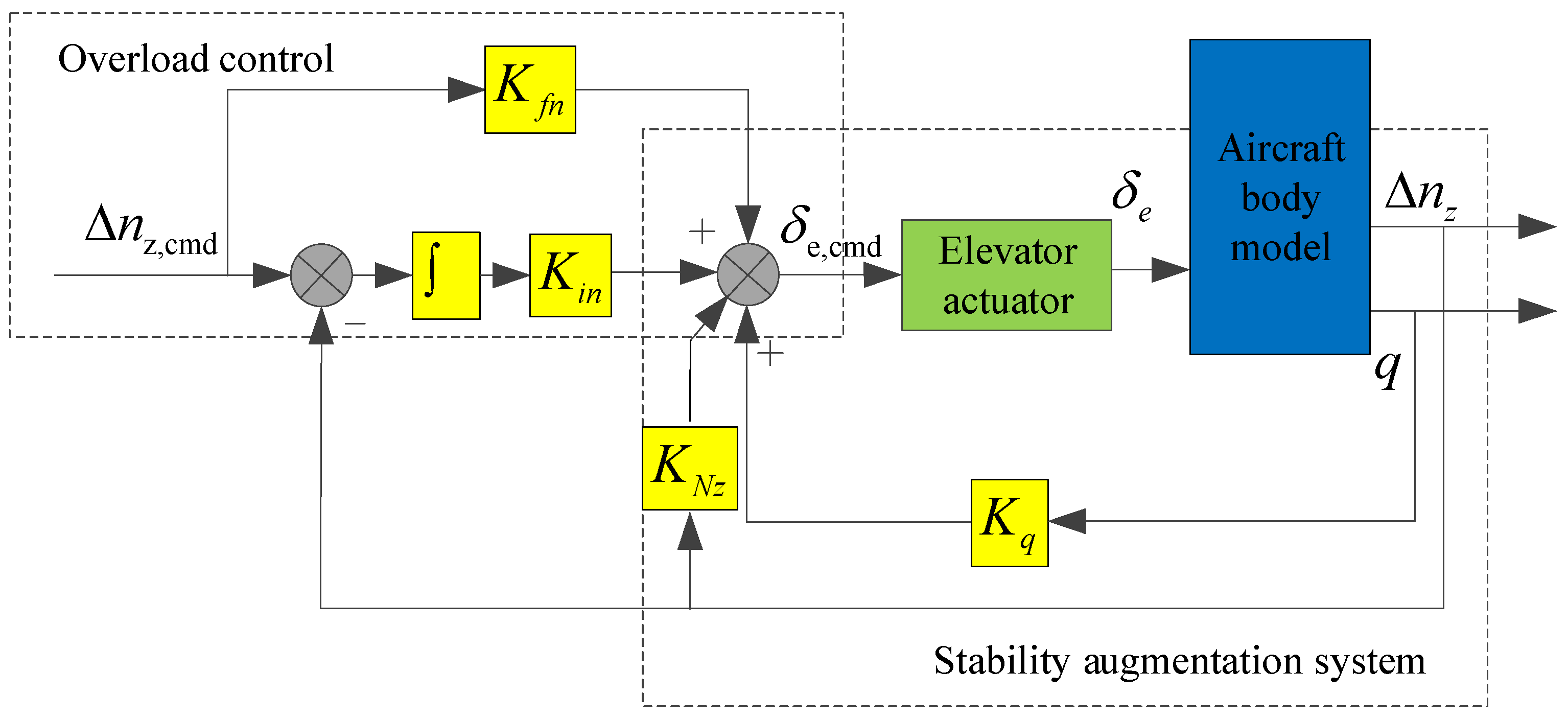
The structure of the longitudinal flight control law is shown in
Figure 1. The longitudinal flight control law consists of the inner loop and the outer loop. In the inner loop, the pitch angular rate
q and overload increment Δ
nz are fed back to improve the longitudinal model characteristics of the aircraft. In the outer loop, the overload increment Δ
nz is used as the control command, that is, the longitudinal displacement of the joystick corresponds to the overload increment command.
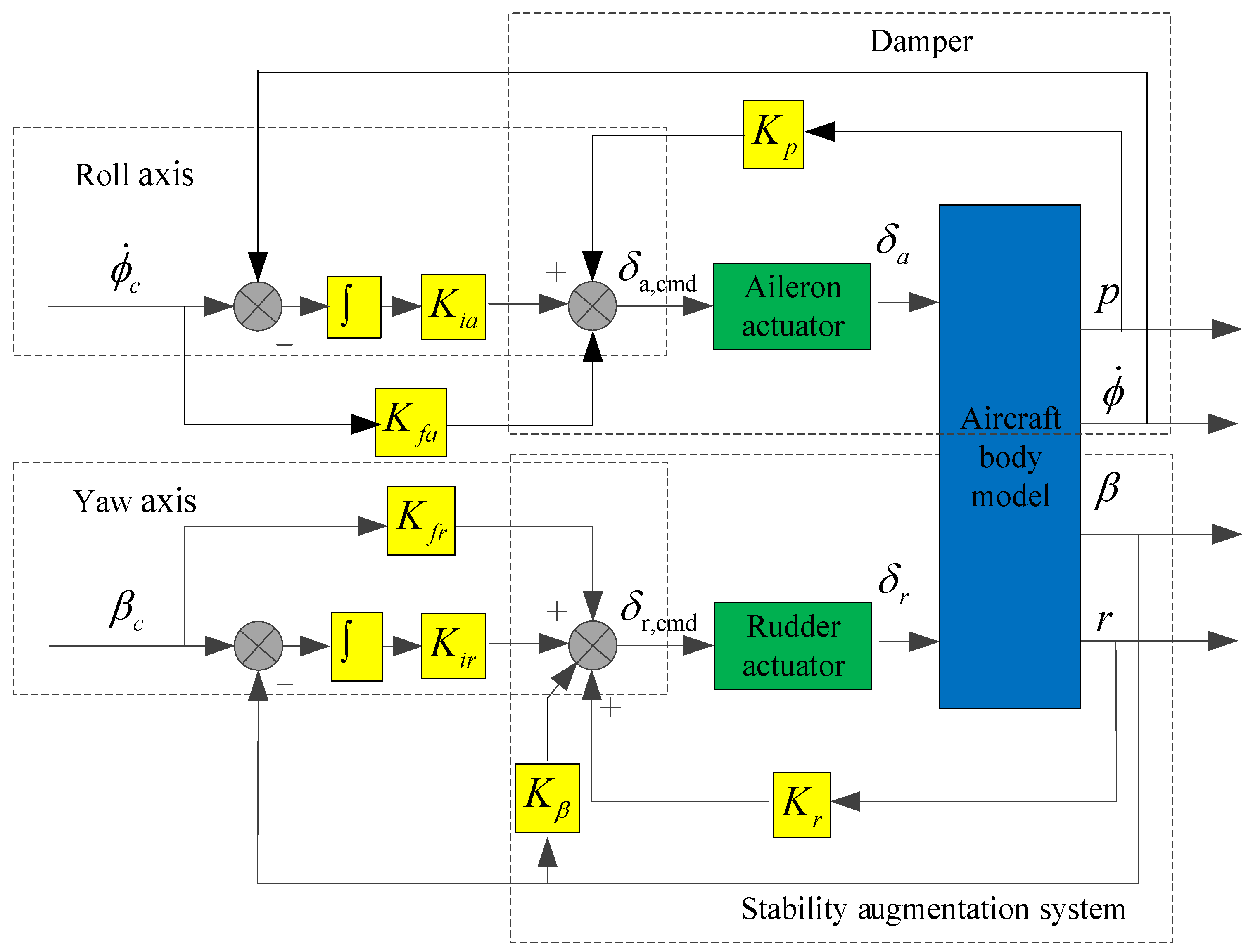
The structure of the lateral–directional flight control law is shown in
Figure 2, including the roll angle control law and the sideslip angle control law, both of which are divided into inner and outer loops. In the inner loop of the roll axis, the roll angular rate
p is fed back to improve the damping characteristics, and in the outer loop of the roll axis, the roll angle rate
is used as the control command, that is, the lateral displacement of the joystick corresponds to the roll angle rate command. In the inner loop of the yaw axis, the yaw angular rate
r and sideslip angle
β are fed back to improve the directional model characteristics of the aircraft, and in the outer loop of the yaw axis, the sideslip angle
β is used as the control command, that is, the displacement of the pedal corresponds to the sideslip angle command.
The parameters of the standby flight control law designed in this study were as follows: Kfn = −0.1, Kin = −0.16, KNz = 0.8, Kq = 0.4, Kfa = −1, Kia = −0.05, Kfr = 1.2, Kir = 1.5, Kβ = 0.8, Kp = 0.4, and Kr = 0.3.
2.2.2. Direct Flight Control Law
The structure of the direct flight control law is shown in
Figure 3, the displacements of the joystick and pedals are directly related to the deflection angle of the elevator, aileron, and rudder. The damper still exists, and the values of its parameters remain unchanged.
The dynamics model of the control surface system can be described as a first-order inertial element, as shown in Equation (7).
where
i =
a,
e, and
r respectively represent the elevator, aileron, and rudder;
T is the control surface response time; the superscript
cmd represents the command; and the
s represents the complex frequency in the Laplace transformation.
The position limits, rate limits, and response time constants of the control surface are shown in
Table 1.
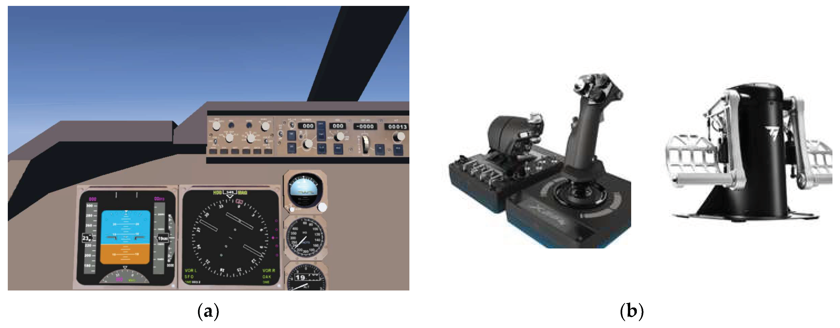
2.3. Joystick, Pedals, and Throttle Model
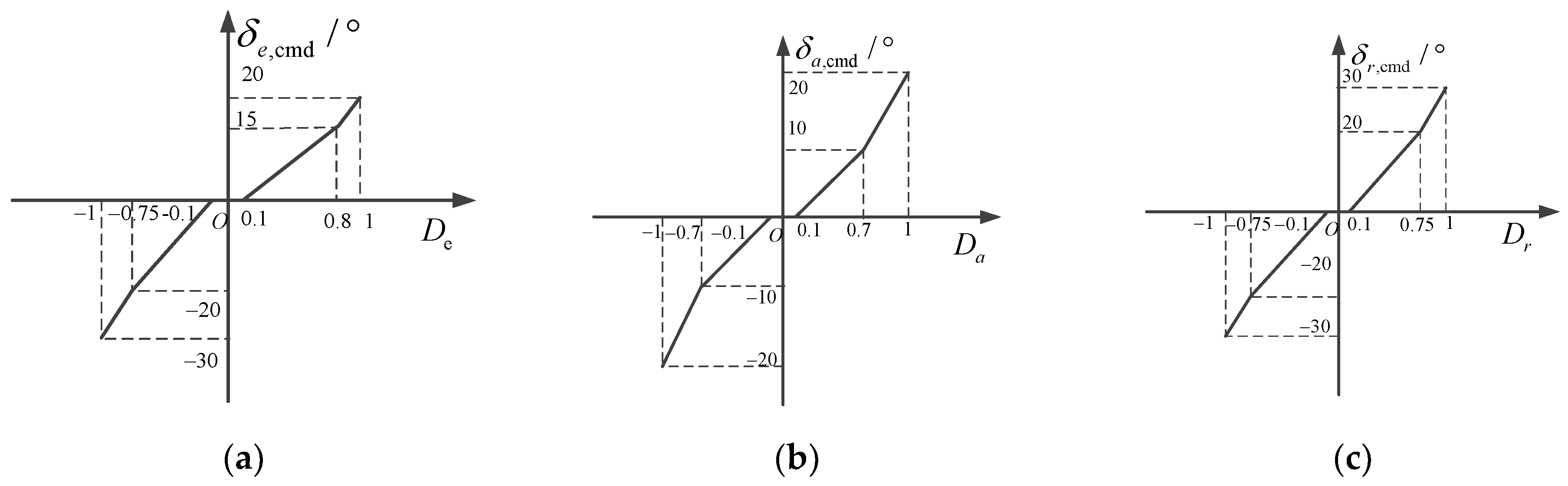
Near the neutral positions of the joystick and pedals, the displacement gradient should be small to meet the needs of the pilot’s accurate control [
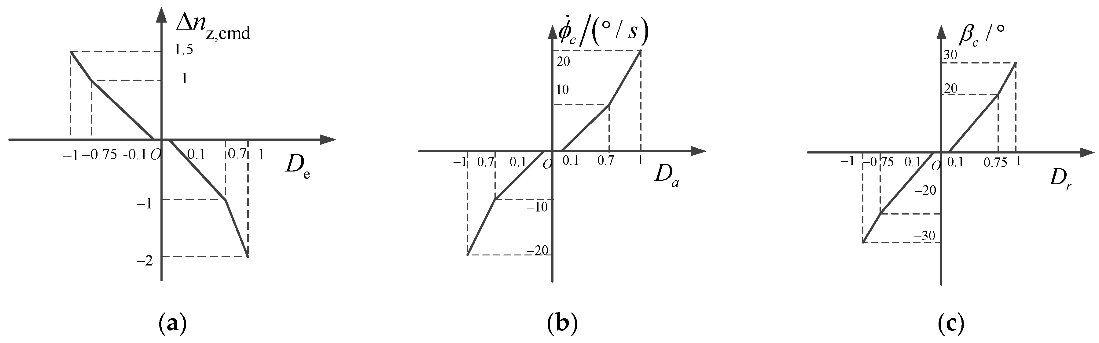
27]. To avoid the pilot’s unconscious manipulation and accidental interference, the displacement dead zone should also be set near the neutral position. When the displacement of the joystick and pedals is large, the displacement gradient should be increased to meet the needs of the pilot for larger amplitude maneuvering. Therefore, it is generally necessary to design the displacement characteristics of the joystick and pedals in segments. The displacement characteristics of the joystick and pedal models under different types of flight control laws are determined as shown in
Figure 4 and
Figure 5.
When the standby flight control law was adopted, the longitudinal control of the joystick corresponded to the overload change between [−2, 1.5], that is, the overload command was between [−1, 2.5], the maximum roll angle rate command was 20°/s, and the maximum sideslip angle command was 30°.
The throttle uses a linear model, that is, when the throttle position is the lowest, the thrust is the minimum, and when the throttle position is at the top, the thrust is the maximum.
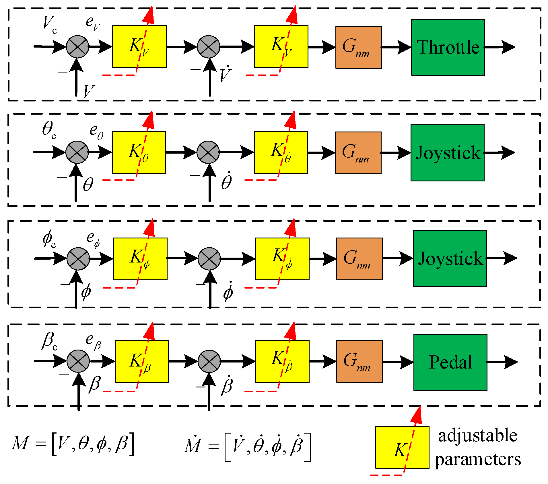
2.4. Adaptive Pilot Model
The pilot model provides a basic framework for understanding the pilot’s maneuvering behavior. To date, a variety of pilot models have been proposed according to different assumptions, including the static and dynamic characteristics of the pilot. Hess proposed a multi-axis pilot model, which controls the aircraft with a combination of output-rate feedback and output-error feedback, and also considers the pilot’s nerve and muscle model [
28]. Based on this theory, the adaptive pilot model of the upset recovery task is established, as shown in
Figure 6.
In
Figure 6,
and
represent the output and output rate of the controlled response variables, where the controlled response variable
M includes speed, pitch angle, roll angle, and sideslip angle.
e is the command tracking error.
Gnm represents a simplified neural and muscular model of the pilot, as shown in Equation (8).
The selection rules of parameters in the multi-axis pilot model were as follows [
29]:
The parameters of the inner loop were selected so that the minimum damping ratio of the inner loop under any oscillation mode was 0.15.
The parameters of the outer loop were selected to make the crossing frequency of the man–machine open-loop model 2 rad/s.
Based on the above rules, the basic parameters for the multi-axis adaptive pilot model were as follows: 1, 12.5, 0.2, 0.44, 8, 1.2, 1.5, and 2.
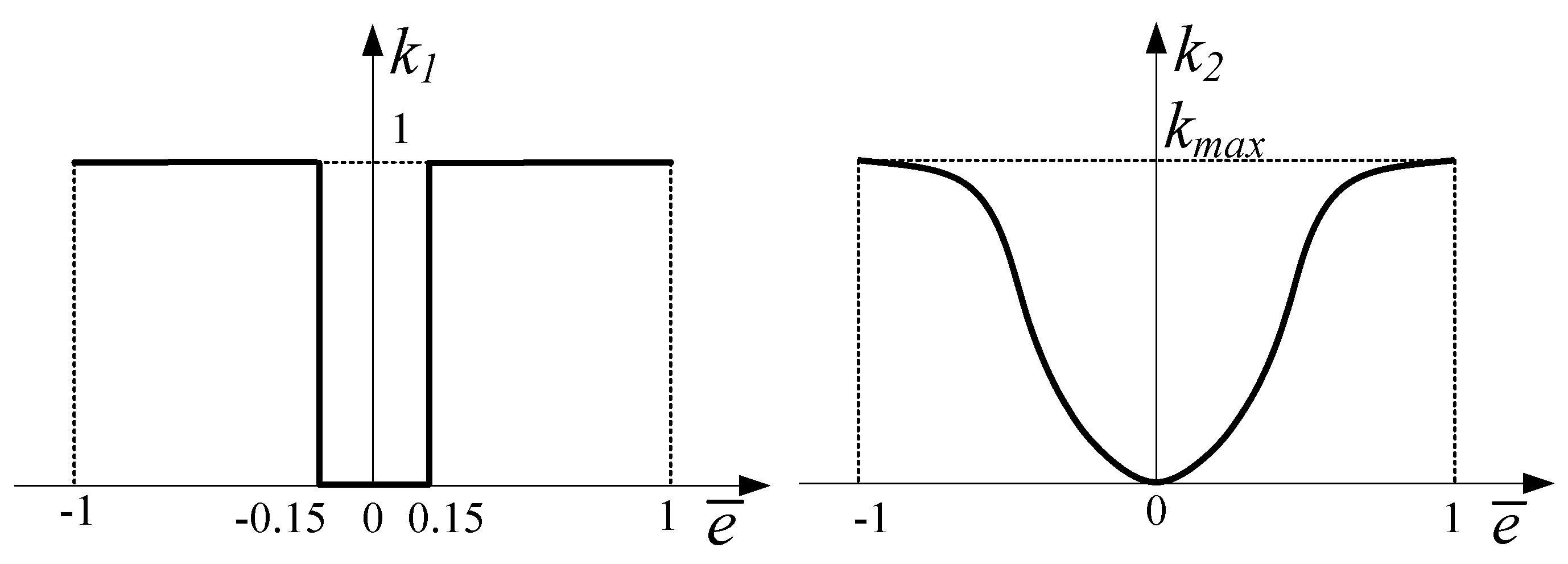
The adaptive pilot model can intelligently adjust the control amplitude according to the deviation between the aircraft state and its command value to make the aircraft smoothly and safely recover from an upset state. In the stages of upset state recovery, the pilot should exercise caution and control the amplitude to be smaller than normal. The adaptive regulation rules were as follows:
where
k1 is the induced adjustment coefficient, which determines whether to adjust, and
k2 is the proportional adjustment coefficient, which determines the size of the adjustment parameters. The sizes of
k1 and
k2 depend on the error between the command and the actual response, as shown in
Figure 7;
is the normalized value of the error; and
kmax determines the size of the pilot’s adaptive ability. In this study,
kmax = 0.5
.
2.5. Upset State Induction
Before 2017, the upset state was often defined by reaching at least one of the following parameter values [
1]:
- a.
Pitch angle greater than 25 degrees;
- b.
Pitch angle less than −10 degrees;
- c.
Roll angle greater than 45 degrees;
- d.
The attitude angles are within the range of the above parameters, but the speed is not consistent with the flight state.
After 2017, the definition of upset was modified so that the definition is no longer limited to specific pitch and roll attitude and velocity parameters [
4]. The aircraft is also considered to enter an upset state when the angle of attack approaches or exceeds the stalling angle of attack. The earlier research on the aircraft aerodynamic model used in this study indicated an angle-of-attack exceedance when 12° or greater is seen [
30]. Therefore, when the angle of attack was greater than 12°, the aircraft was also considered to be in the upset state in this study.
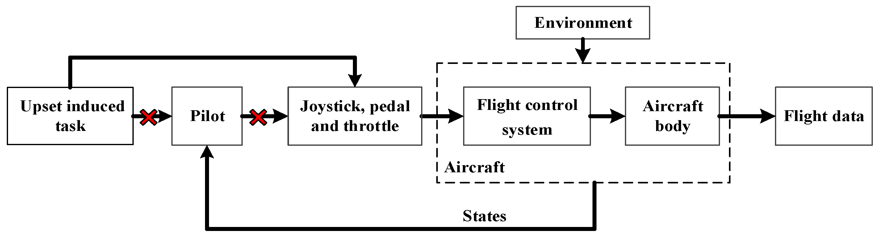
Based on the aircraft body dynamics model; flight control system model; joystick, pedals, and throttle model; pilot model; and atmospheric environment model, the man–machine closed-loop models were established. The overall model disconnects the pilot model and directly applies a gradient of joystick displacement with different speeds and directions to the joystick model to induce the airplane to enter the upset state, as shown in
Figure 8. The initial speed and altitude of the aircraft are given randomly, and the simulation time is given randomly. The specific parameters for the aircraft to perform the induced task are shown in Equation (10).
where
H0 is the initial altitude,
V0 is the initial speed,
T is the simulation time, and
Jp is the longitudinal displacement of the joystick.
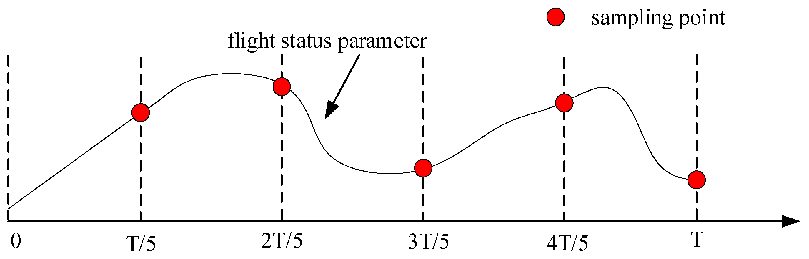
Considering that the maximum overload that the real aircraft can withstand is limited by the structure, and the aircraft cannot safely recover from an upset state at too low of an altitude, the simulation was stopped when the normal overload of the aircraft was greater than 3 or less than −1.5, or the altitude was less than 1000 m. After obtaining 2000 flight data sets based on the Monte Carlo simulation, the flight data was sampled, and five flight status points were selected for each simulation. The sampling rule is shown in
Figure 9.
After obtaining a total of 10,000 flight state points, 4196 points that satisfied the definition of the aircraft in an upset state were screened in terms of the definition of an upset state, that is, meeting any of the above conditions a, b, c, and d or meeting the angle of attack being greater than 20° requirement, and these points were used as the initial value of the aircraft recovery from the upset state. The aircraft flight state parameters contained in each point are shown in Equation (11).
where
nx,
ny, and
nz are respectively the axial, lateral, and normal overload in the body-axis;
δp is the throttle position;
δs is the horizontal stabilizer position; and the subscript 0 represents the initial value.
3. Upset Recovery Strategy Based on Reinforcement Learning
3.1. Markov Decision Model
Markov modeling is the basis of upset recovery via reinforcement learning. It is necessary to determine the state, action, reward function, and termination condition of the Markov decision model.
3.1.1. States
According to the definition of an upset state and the initial values of the aircraft recovery from the upset state, the continuous state variable adopted in this study is shown in Equation (12).
It is worth noting that at the initial moment of simulation, the initial state of the aircraft is not the trim value, but the initial value of the aircraft recovery from the upset state given at random, as shown in Equation (11).
3.1.2. Actions
The actions directly affect the training effect of strategies. To quickly change the aircraft state at the initial stage of upset recovery and precisely adjust the aircraft state at the later stage of upset recovery, the action adopted in this study was the deflection change value of the control surface, as shown in Equation (13), where the number of actions was 27, and the thrust was set to 0 to prevent speed exceeding the limit or height loss [
17].
where Δ
δe is the command for the elevator deflection change value, Δ
δa is the command for the aileron deflection change value, and Δ
δr is the command for the rudder deflection change value.
3.1.3. Reward
The design of the reward function directly affects the training effect of the strategy. The reward in the process of upset recovery includes the situational reward and immediate reward.
The function for the situational reward can be expressed as
where
rα,
rβ,
rϕ,
rθ,
rp,
rq,
rr, and
rNz represent the advantage function of the angle of attack, sideslip angle, roll angle, pitch angle, roll angular rate, pitch angular rate, yaw angular rate, and normal overload, respectively.
kα,
kβ,
kϕ,
kθ,
kp,
kq,
kr, and
kNz are used to modulate the weight of the single advantage function in the situational reward function.
θ0 and
Nz0 are the expected aircraft pitch angle and normal overload.
ωαngle,
ωpalstance, and
ωNz are used to modulate the weight of the angle advantage function, the angular rate advantage function, and the normal overland advantage function in the situation reward function. In this study,
kα,
kβ,
kϕ, and
kθ were 0.25 pi;
kp,
kq, and
kr were 0.15 pi;
kNz was 3;
θ0 was 0.08 (about 4.5°);
Nz0 was 1; and
ωαngle,
ωpalstance, and
ωNz were 1/3.
The function for the immediate reward value can be expressed as
It is difficult for the aircraft to directly recover the steady and level flight state because the selected actions are the deflection change value of the control surface. Therefore, when the angle of attack, sideslip angle, and attitude angle of the aircraft are all small, for example, the angle of attack and the pitch angle are less than 12° and greater than −5°, the absolute value of roll angle is within 10°, the absolute value of the sideslip angle is within 5°, and the absolute values of the angular rates are within 5°, the aircraft is considered to enter the normal and safe state. The pilot can smoothly and easily control the aircraft to recover a steady and level flight state.
The function of the total reward value can be expressed as
3.1.4. Termination Condition
The single training was terminated when the aircraft was in a normal state and the immediate reward was obtained. In addition, to reduce the strategy training time and improve the convergence efficiency, the single training was terminated when the aircraft state deviated too much from the normal condition, that is, the aircraft angle of attack was greater than 85°, the normal overload was greater than 3.25 or less than −1.75, the absolute value of roll angle was greater than 90°, the absolute value of the sideslip angle was greater than 45°, the absolute value of the triaxial angular rate was greater than 60°/s, and the aircraft height was less than 500 m. The termination conditions are shown in Equation (17).
3.2. Training Algorithm
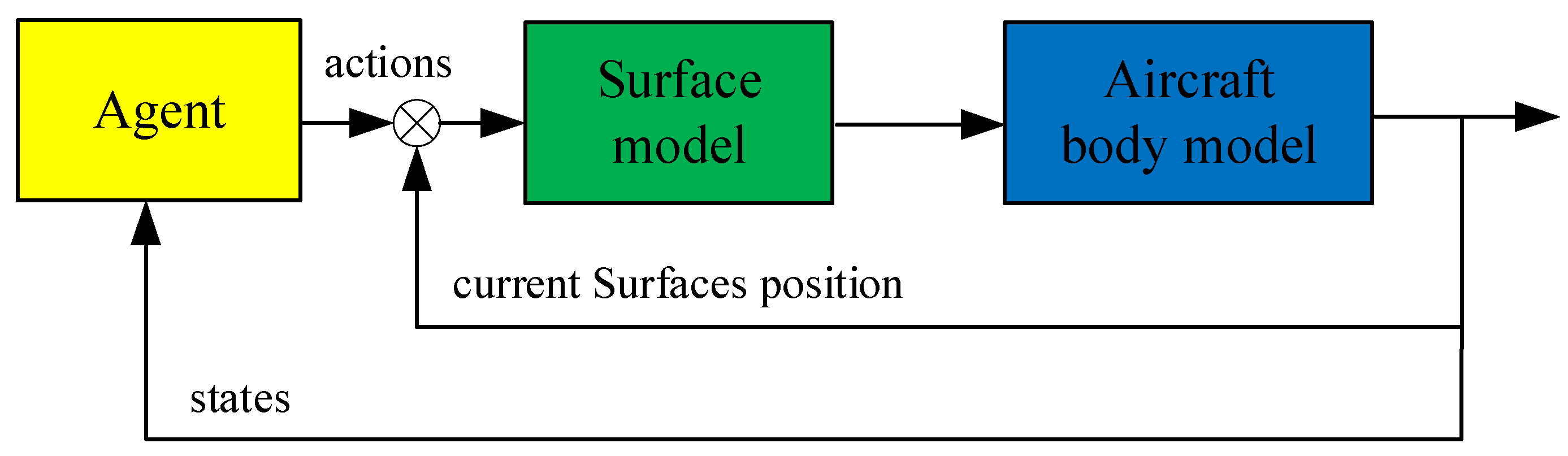
The interaction process of the agent and environment is shown in
Figure 10. The actions of the agent are the deflection change value of the control surface and the control surface commands are the superposition of the actions and the current surface position.
The PPO is a random strategy algorithm with strong robustness and displays excellent sampling efficiency and algorithm performance. It is the preferred algorithm of Open AL. Therefore, the PPO was applied to train the upset recovery strategy. The process of PPO is shown in Algorithm 1 [
18].
| Algorithm 1: PPO. |
| for iteration = 1, 2, …, do |
| for actor = 1, 2, …, N do |
| Run policy πθold in the environment for T timesteps |
| Compute advantage estimate , ⋯, ; |
| end for |
| Optimize surrogate L wrt θ, with K epochs and minibatch size M < NT |
| θold ← θ |
| end for |
Here, N is the number of parallel actors, t is the sampling time, K is the number of epochs, M is the minibatch size, πθ is the stochastic policy, is the estimation of the advantage function at timestep t, L is the surrogate objective, and θ is the vector of policy parameters.
The values of the parameters in the PPO algorithm are shown in
Table 2.
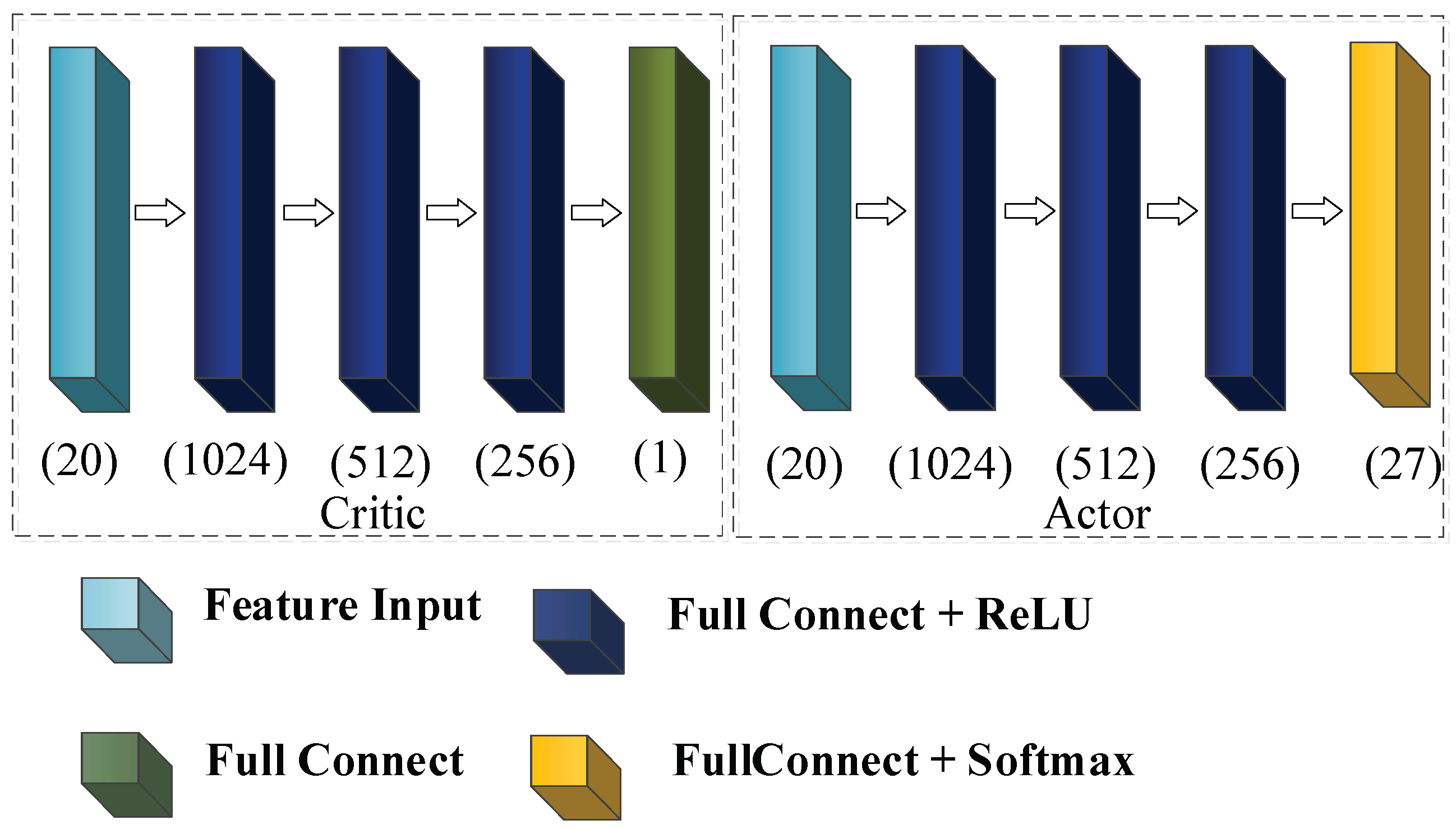
The structure of the network in the PPO algorithm is shown in
Figure 11.
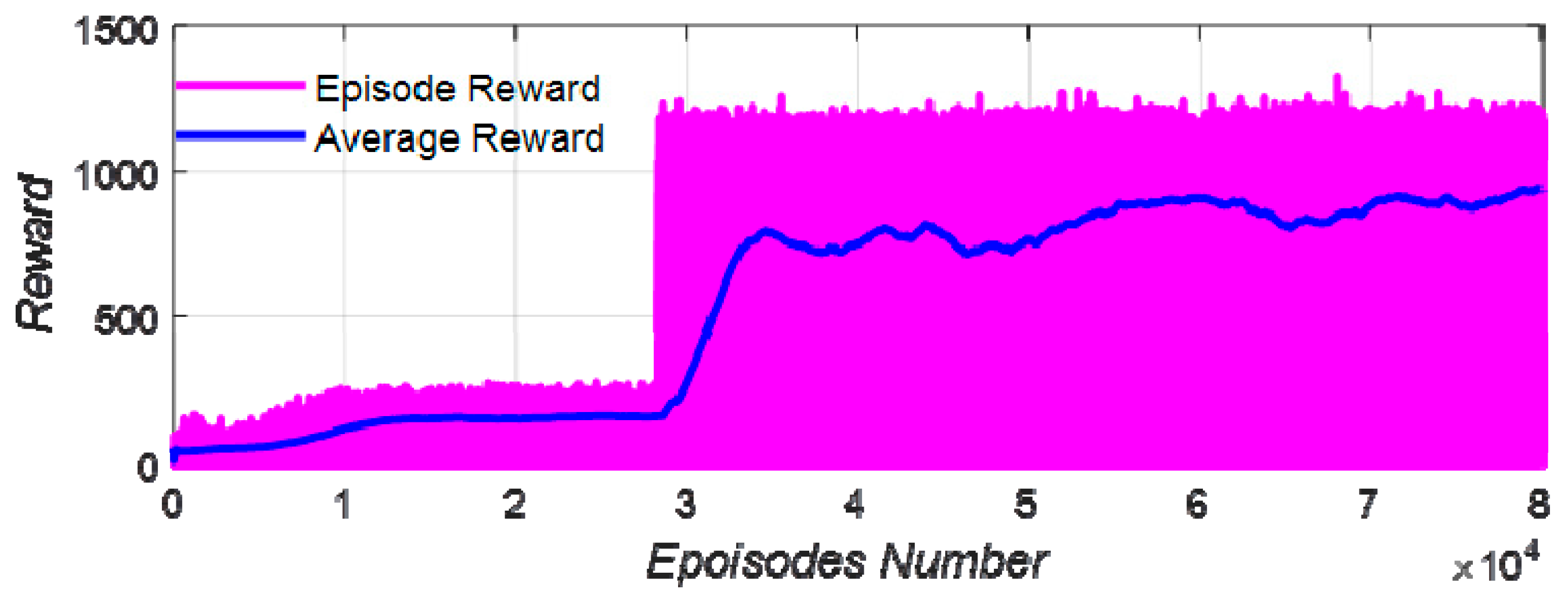
The computer configuration used for training was as follows: CPU—I7-12700 and GPU—RTX2060. The training time was 2.75 × 10
5 s, and the training results are shown in
Figure 12.
According to the training results, after 35,000 iterations, the strategy converged and the average reward was stable at about 800. It was shown that the training of the upset recovery strategy was successful.
3.3. Monte Carlo Mathematical Simulation
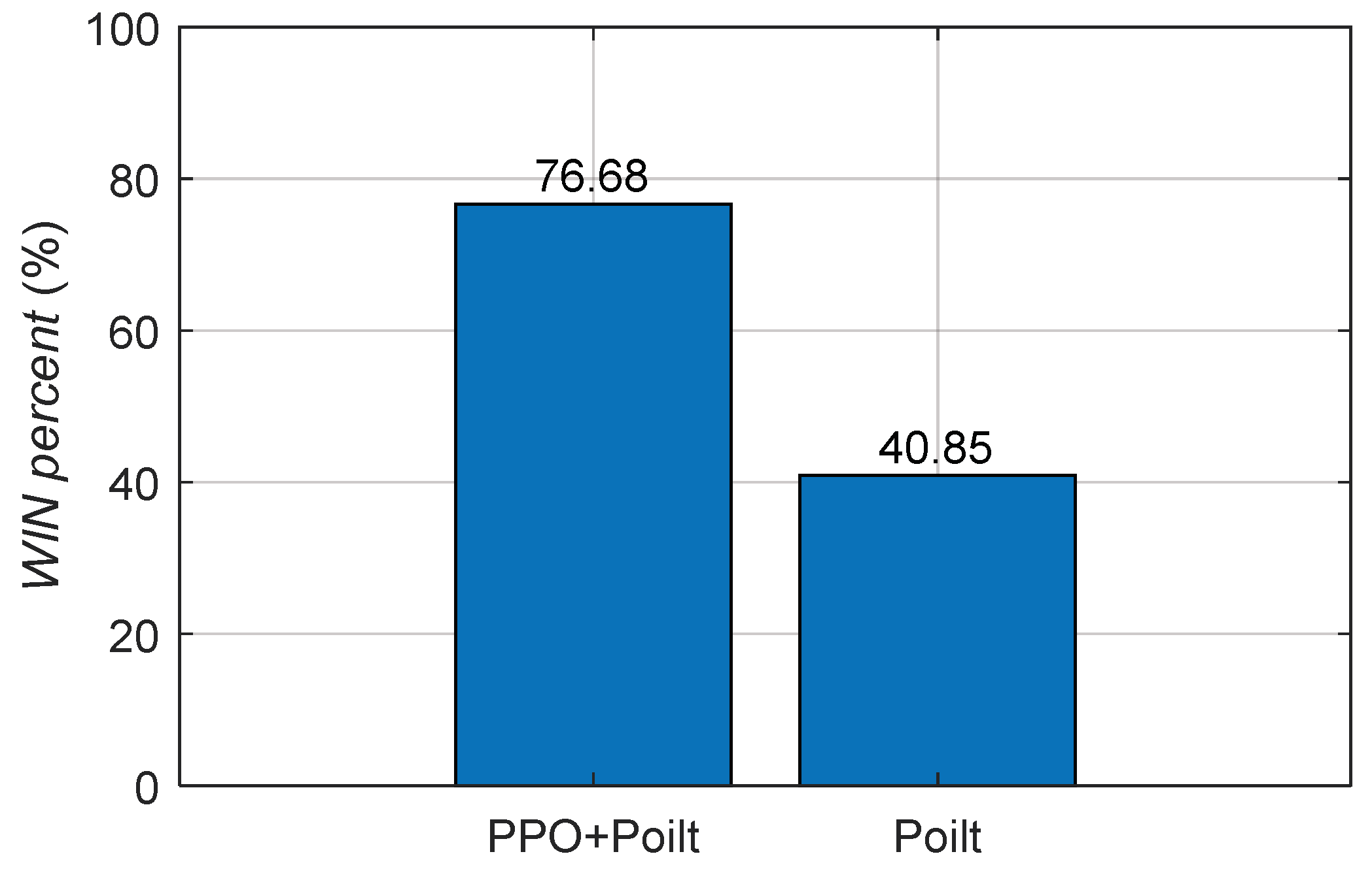
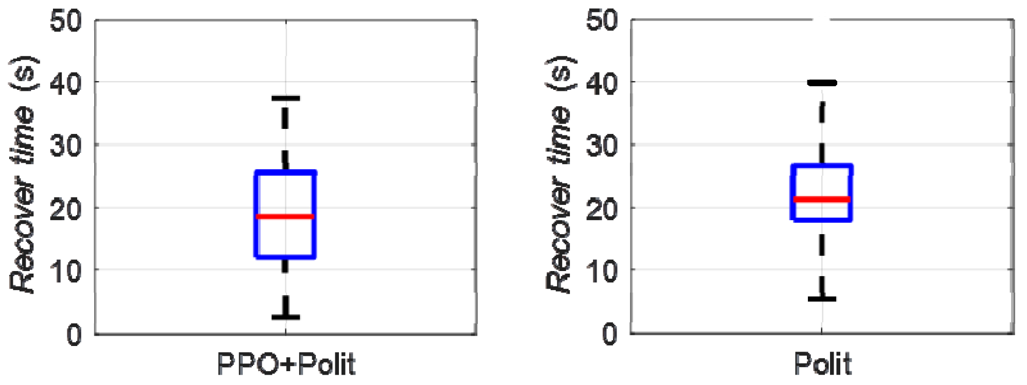
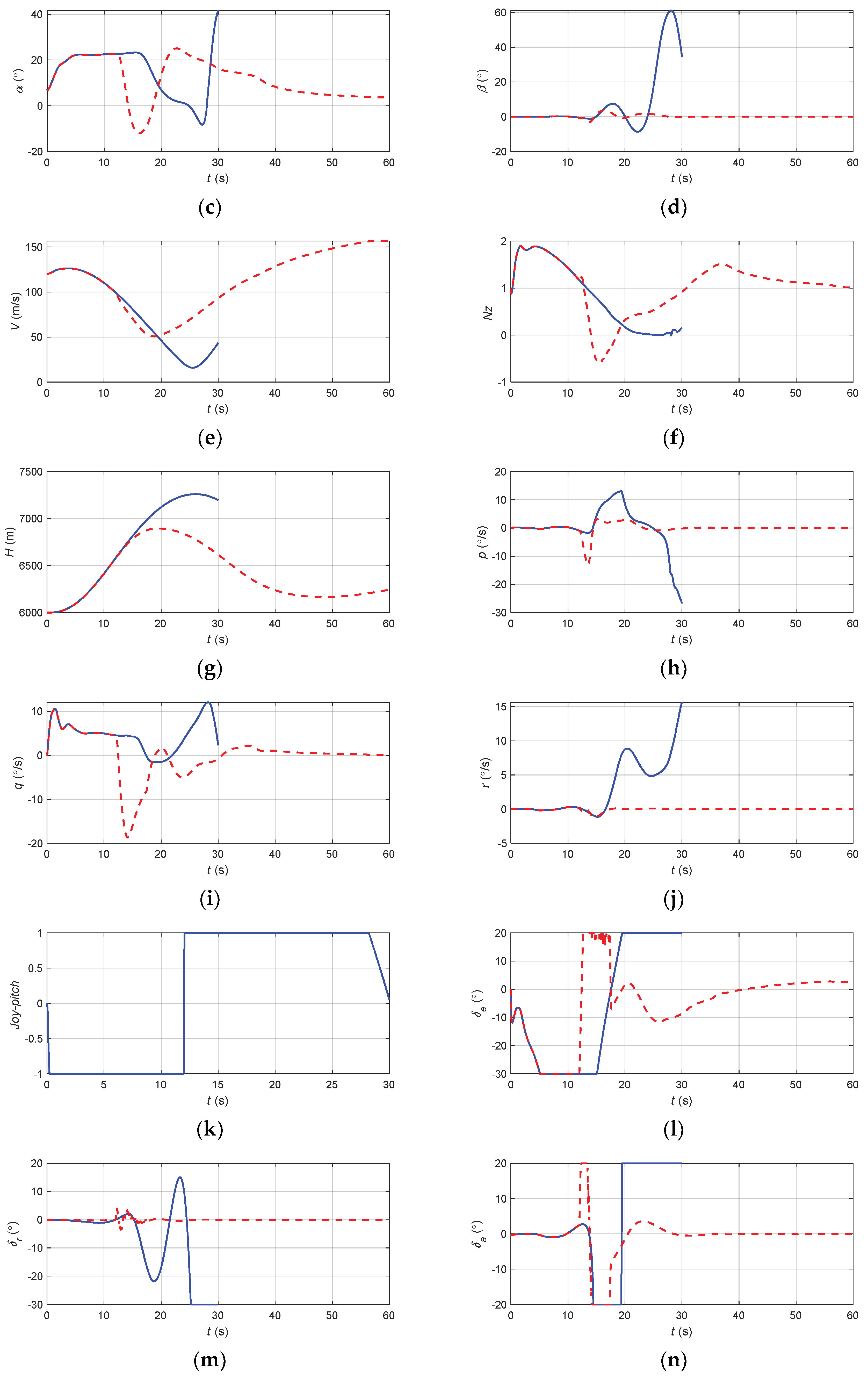
The Monte Carlo mathematical simulation method was used to carry out multiple digital virtual simulations of upset recovery. The difference between the reinforcement learning method based on PPO and the single pilot control method was evaluated quantitatively using the success rate and the time of upset recovery, as shown in
Figure 13 and
Figure 14.
When the pilot control method was applied, the success rate of upset recovery was 40.85%, the median time for the aircraft to recover from the upset state to steady and level flight was 21.4 s, the upper quantile was 27.8 s, while the lower quantile was 17.8 s; when the reinforcement learning strategy based on PPO was applied, the success rate of upset recovery was significantly increased to 76.88%, the median time for the aircraft to recover from the upset state to steady and level flight was reduced to 18.5 s, the upper quantile was reduced to 25.6 s, while the lower quantile was 12.1 s. The success rate of upset recovery was obviously improved, and the time was significantly reduced.
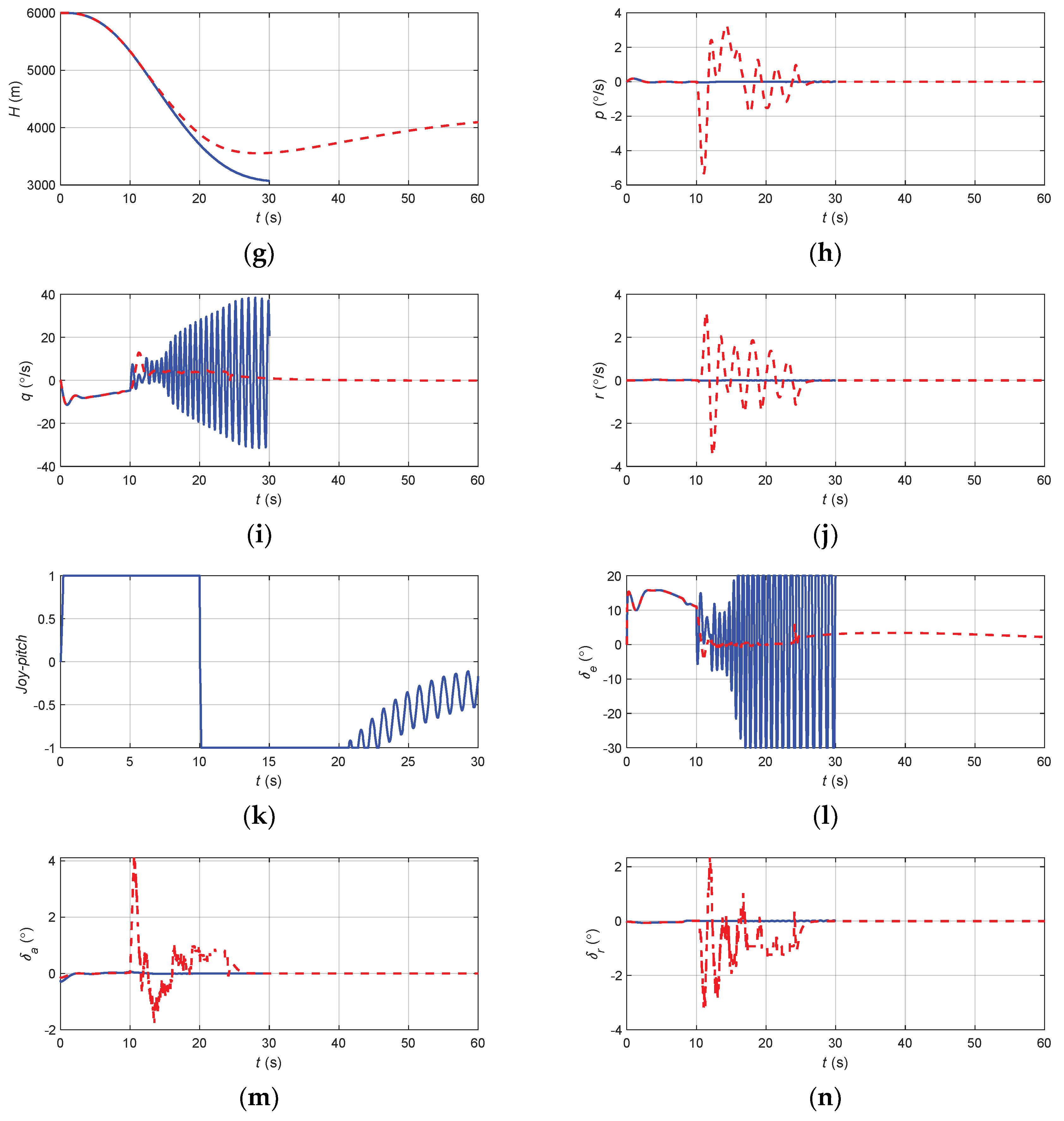
The results of the typical upset recovery effect and Monte Carlo simulation show the effectiveness and superiority of the upset recovery strategy based on reinforcement learning.
4. Pilot Assistance System
4.1. Upset Recovery Safety Envelopes
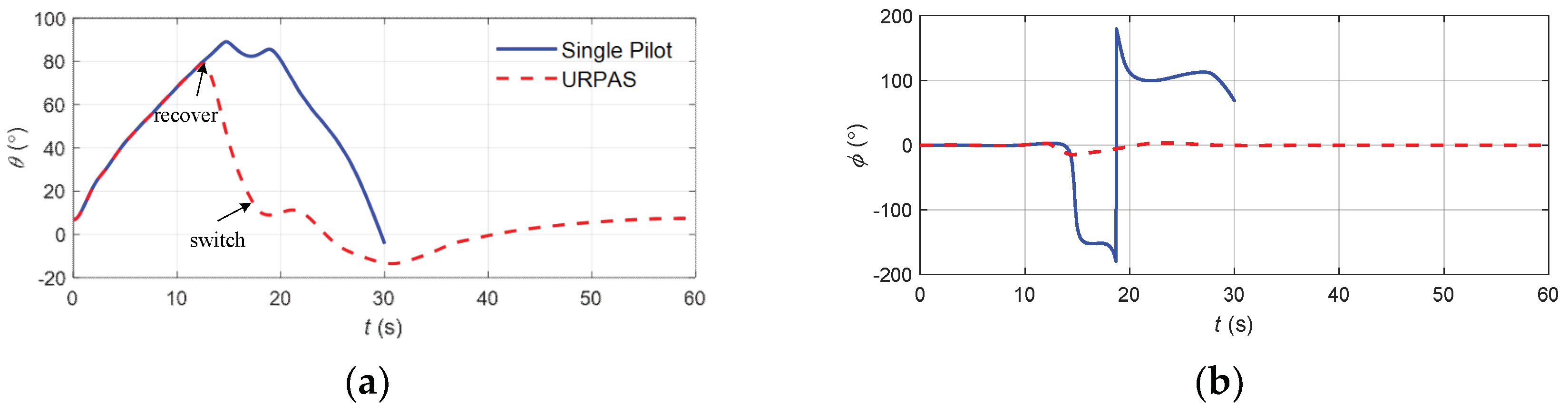
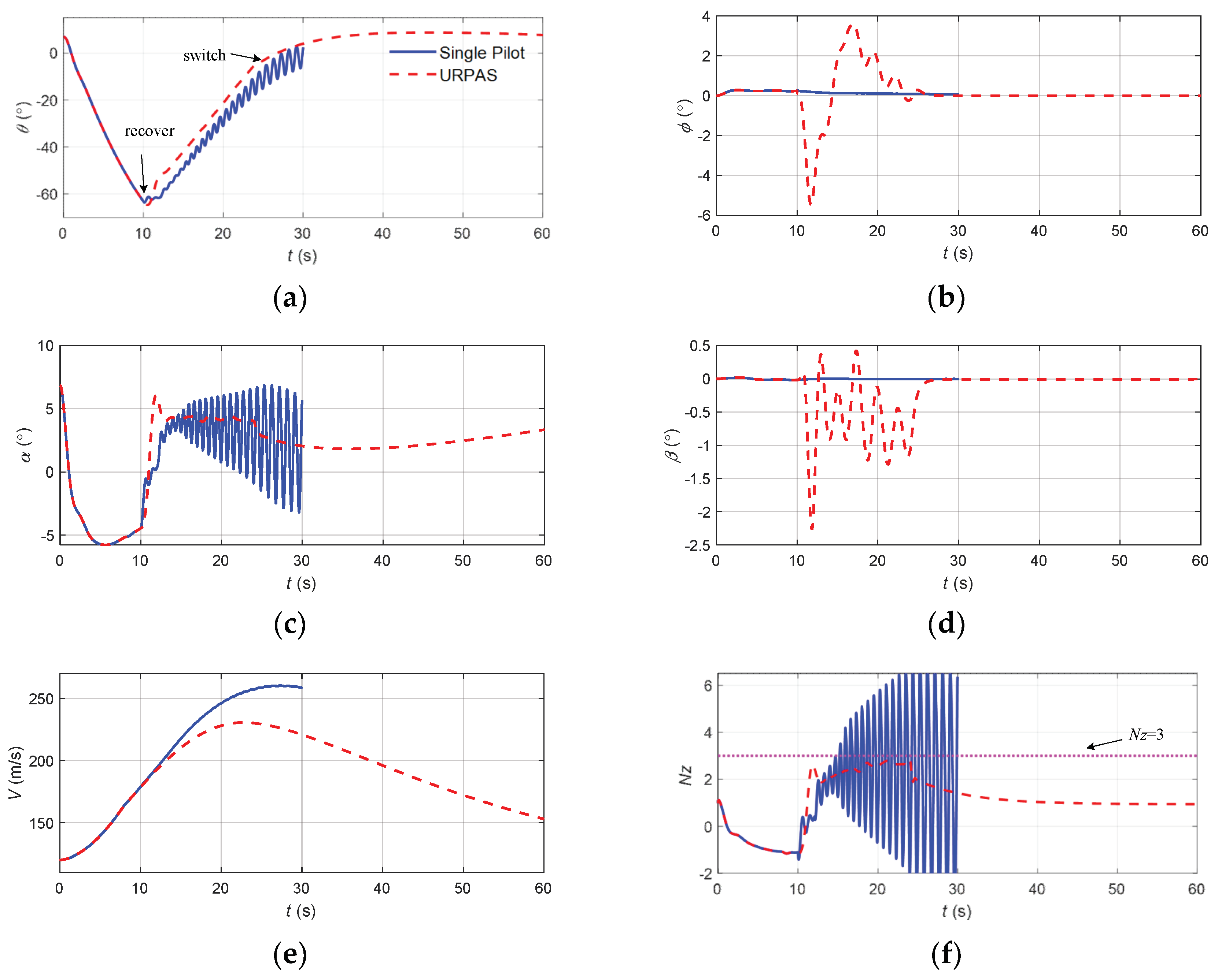
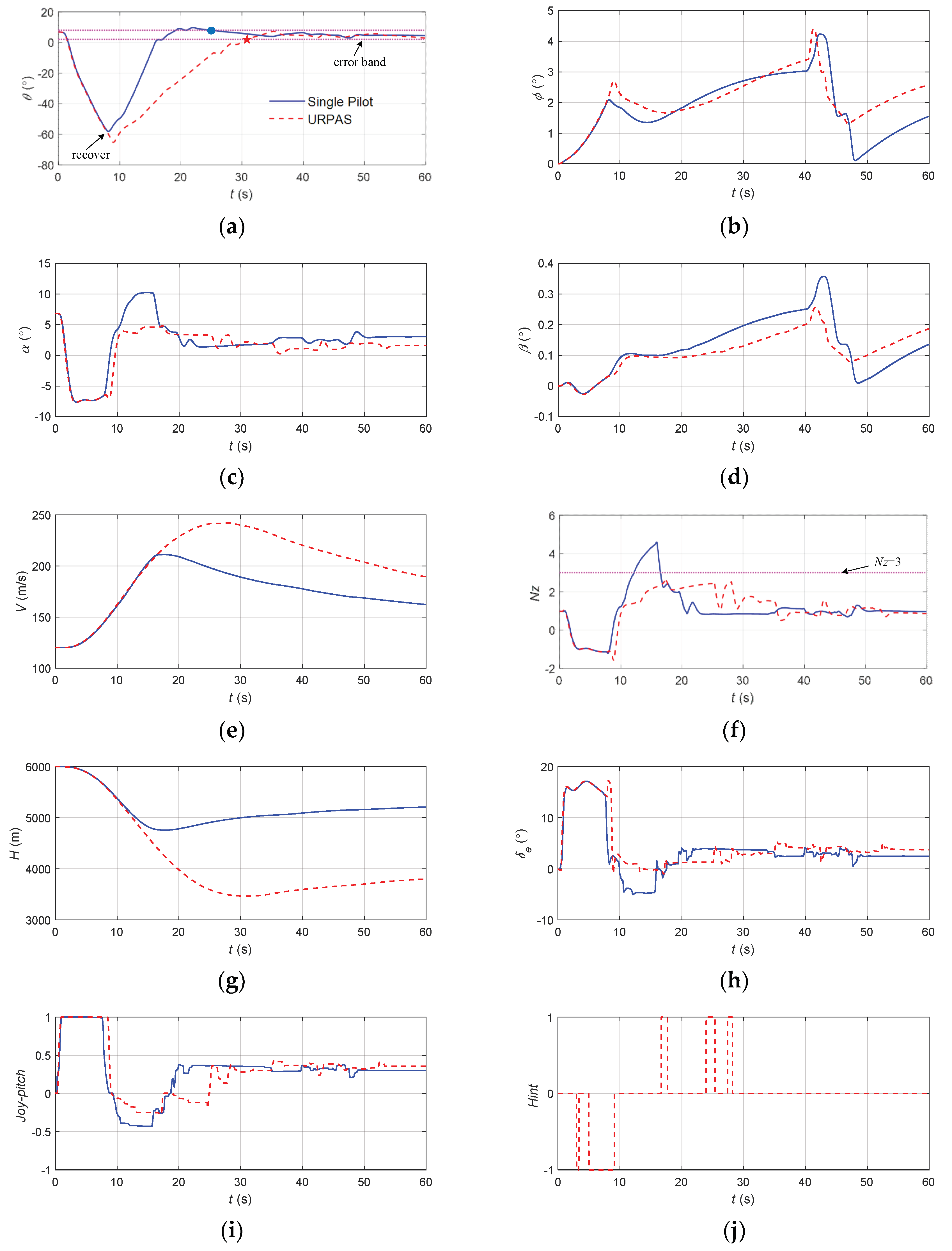
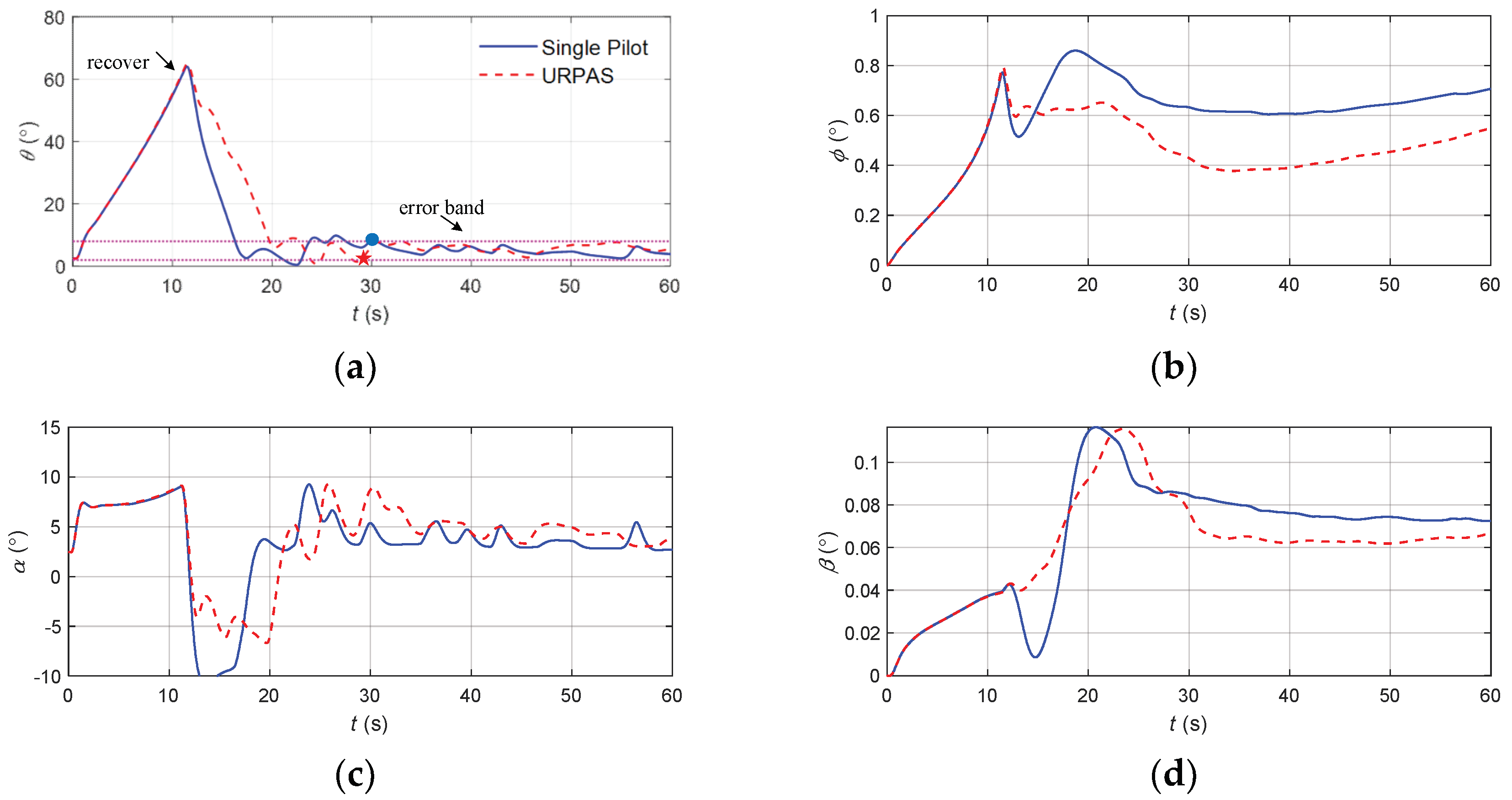
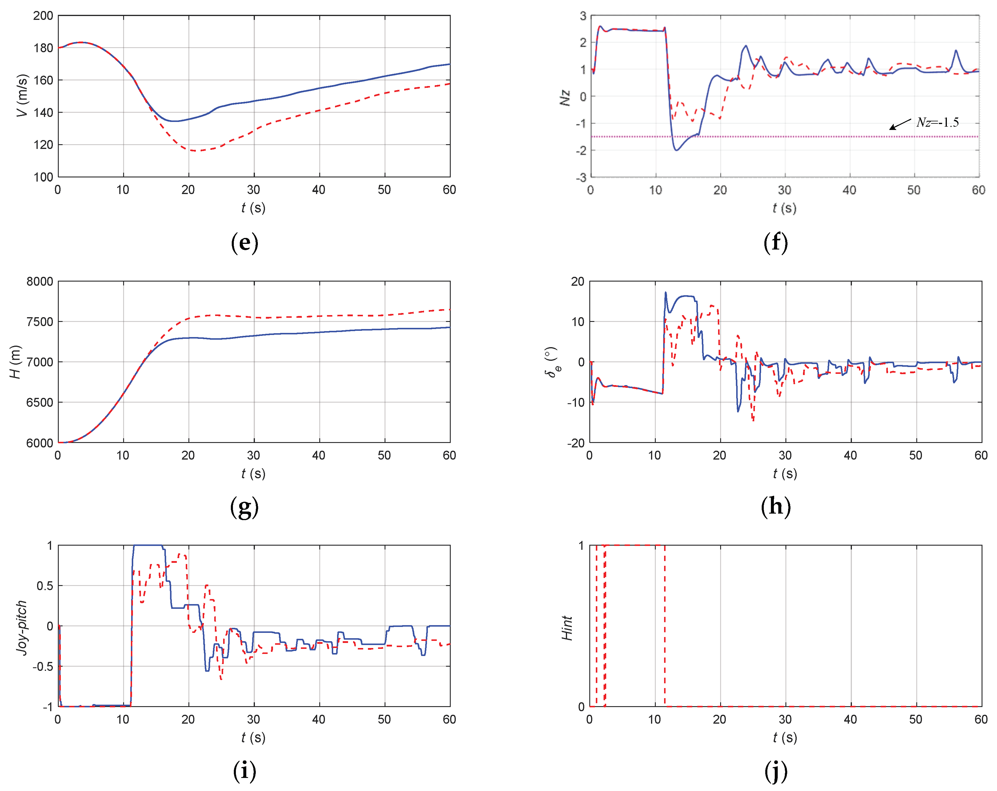
The results of the two upset recovery strategies and the flight state parameters at the initial time are plotted in
Figure 15.
According to
Figure 14, the angle of attack, pitch angle, and speed directly affected the result of the upset recovery, and the dividing line was clear. The altitude, sideslip angle, roll angle, and other flight state parameters had no obvious influence on the result of the upset recovery.
If the angle of attack and pitch angle met Equation (18), the reinforcement learning method could be used to make the aircraft safely recover from the upset state. If these parameters met Equation (19), the pilot could safely control the aircraft to recover from the upset state without the reinforcement learning strategy.
When the speed was above 78 m/s (about the stall speed), the aircraft could be safely recovered from the upset state; when the speed was below 40 m/s, no matter what kind of recovery strategy was used, the aircraft could not safely recover from the upset state.
4.2. System Operating Mode
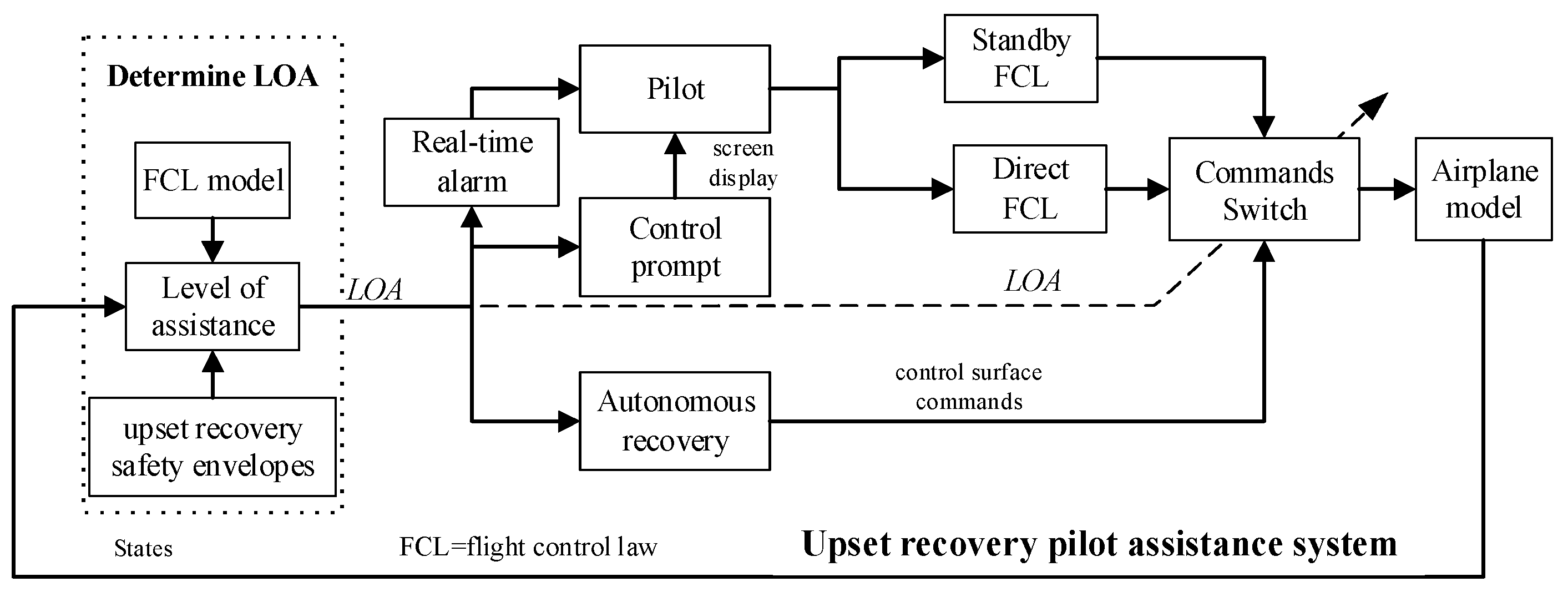
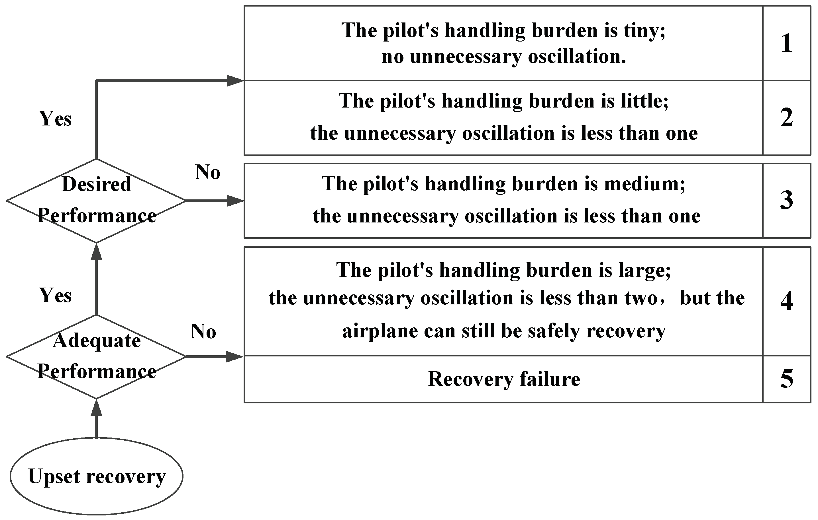
Aiming at the upset state of large angle of attack and large attitude angle, the operating mode of URPAS was designed, as shown in
Figure 16, including the upset real-time alarm module, control prompt module, and autonomous recovery module. The level of assistance (LOA) was divided into four levels: 0, 1, 2, and 3, corresponding to the three operating modes of the URPAS: “no assistance”, “alarm warning”, “cooperative control”, and “autonomous recovery”.
The detailed operating mode of URPAS is as follows:
(1) Determine the level of assistance based on the upset recovery safety envelopes established in
Section 4.1 and the existing flight control law model to determine the LOA.
(2) When the aircraft flight states are within the normal safety envelopes [
3], as shown in Equation (20), it is determined that the aircraft has not entered the upset state at this time, the LOA is 0, the operating mode of “no assistance” is adopted, and the pilot has full control of the aircraft.
(3) When the aircraft flight states are outside the normal safety envelopes, but still within the upset recovery safety envelopes of the pilot, it is determined that the aircraft has entered the upset state at this time. If the flight control law mode has an overload protection function, the LOA is 1, the operating mode of “alarm warning” is adopted, the URPAS sends a sound alarm signal to the pilot, and the pilot has full control of the aircraft.
(4) When the aircraft flight states are outside the upset recovery safety envelopes of the pilot, it is determined that the aircraft has entered the upset state at this time. If the pilot still wishes to manually control the aircraft, the flight control law can be switched to the direct flight control law, the operating mode of “cooperative control” is adopted, and the LOA is 2. The URPAS sends an alarm signal to the pilot, immediately starts the control prompt module, and displays the maneuvering action suggestions through the screen. Under the premise of retaining the pilot’s control authority, the recovery success rate is improved and the pilot’s control burden is reduced.
The maneuvering action suggestions are based on the actions of the reinforcement learning strategy, that is, the deflection change commands of the control surface. For example, if the deflection change command of the elevator is 0°, the maneuvering action suggestion is 0 and the pilot is advised to maintain the existing strategy for small and stable control. If the deflection change command of the elevator is +2°, the maneuvering action suggestion is +1 and the pilot is advised to push the joystick appropriately. If the deflection change command of the elevator is −2°, the maneuvering action suggestion is −1 and the pilot is advised to pull the joystick appropriately.
(5) When the aircraft flight states are outside the upset recovery safety envelopes of the pilot, it is determined that the aircraft has entered the serious upset state at this time. If the pilot does not want to manually control the aircraft, the operating mode of “autonomous recovery” is adopted and the LOA is 3. The control surface commands are changed from the pilot’s control to the reinforcement learning strategy, the URPAS temporarily takes over the aircraft and automatically controls the aircraft to recover from the upset state. When the aircraft enters a safe state, as shown in Equation (21), the control strategy is switched to the pilot control.
6. Conclusions
In order to form the upset recovery safety envelopes, improve the recovery success rate and effect of aircraft in the upset state, and reduce the handling burden of the pilot, we proposed an upset recovery strategy and pilot assistance system (PAS) based on reinforcement learning. Compared with traditional pilot control, the success rate of upset recovery based on reinforcement learning was obviously improved from 40.85% to 76.88%, and the median time for the aircraft to recover from the upset state to steady and level flight was significantly reduced from 21.4 to 18.5 s. The aircraft upset recovery safety envelopes were formed based on the correspondence between the flight state, the recovery method, and the recovery result. The normal safety envelope boundaries were −5° < α < 20° and −10° < θ < 25°. The upset recovery safety envelope boundaries of the pilot were α < 45°, α < 0.57θ + 45°, α < −0.45θ + 45°, −35° < θ < 60°, and V > 78 m/s. The upset recovery safety envelope boundaries of the PPO were α < 75°, α −2.25θ + 210°, θ < 80°, and V > 40 m/s. The level of assistance (LOA) of the upset recovery pilot assistance system (URPAS) was divided into four levels: 0, 1, 2, and 3, corresponding to the three operating modes of the URPAS: “no assistance”, “alarm warning”, “cooperative control”, and “autonomous recovery”. The results of the digital virtual flight simulation and ground flight test show the effectiveness and superiority of the aircraft upset recovery strategy and the PAS established in this study.


