Abstract
The use of film cooling technology is one of the most effective ways to minimize the damage to wall materials caused by the high-temperature environment in a ramjet. Optimization of the design to achieve the highest film cooling efficiency on the hot wall is the focus of current research. Due to the large number of parameters affecting the film cooling efficiency and the interactions between them, an improved orthogonal design-of-experiments method is chosen to investigate the contribution of different parameters. Flat plate film cooling and transverse groove film cooling are simulated numerically. The results indicated that the contribution of each parameter is ranked as hole spacing (S/D) > incidence angle > blowing ratio for flat plate film cooling; hole spacing > transverse groove depth > blowing ratio > incidence angle for transverse groove film cooling. The film cooling efficiency is inversely proportional to the size of the flow field area affected by the vortex ring and directly proportional to the size of the vortex intensity. Transverse groove film cooling forms a more complete film in most cases, which is better than flat plate film cooling. Within the scope of this study, a complete film at S/D > 2.0 cannot be generated on the flat plate, which should not be used in ramjet.
1. Introduction
The ramjet is a cutting-edge aerospace science and technology for high-speed flight [1,2]. As the flight speed of ramjet engines increases, there are a series of complex problems that need to be studied and solved [3,4,5]. The first requirement is to solve the thermal barrier problem, where excessive thermal stresses can lead to wall cracking. Film cooling technology can be applied to the design of combustion chamber thermal protection for ramjet engines to improve their combustion stability [6,7,8]. In the ramjet, the velocity of the air entering the combustion chamber is required to be subsonic and compatible with the velocity of flame propagation. However, the ramjet generally operates at supersonic flight conditions. Therefore, it is necessary to decelerate and pressurize the air in the inlet channel with a series of shock waves or cross-sectional changes in inner channels [9,10,11].
Film cooling provides thermal protection to the blade metal wall and downstream of the hole by injecting colder air on the outer surface, forming an insulating layer between the hot main flow and also the surface to be cooled, thereby reducing heat transfer to the surface [12,13,14]. Film cooling technology has been widely used in various fields, such as aerospace, and optimizing gas-film cooling systems is mainly focused on in the investigations. The criteria for evaluating a film cooling system are to provide sufficiently good protection while consuming the least amount of coolant. The cooling effect is usually evaluated in studies based on data on the cooling efficiency of the flow field walls.
For the study of film cooling with transverse grooves, a triangular design of the groove at the jet exit was designed by Khalatov et al. [15], and the three corners were chamfered. The permanent increase of the average spatial film cooling efficiency with the increase of the blowing ratio was proved by the numerical calculations. The film cooling performance of transverse groove film cooling and plate film cooling at blowing ratios of 0.5 and 1.0 was investigated by Hou et al. [16] using large eddy simulation. The simulation results showed that the presence of the transverse groove enhanced the spreading momentum of the coolant, which led to a wider transverse diffusion on the wall surface. At the same time, the formation of a counter-rotating vortex pair (CRVP) [17] was suppressed, which reduced its diffusion ability in the normal direction and allowed it to adhere to the wall better, forming a good protective film. Bunker et al. [18] proposed a film hole structure called a cratered film hole, in which a circular hole enters a shallow right circular cup or depression in the surface. Flat plate tests showed an improvement of about 50% over the round hole at blowing ratio (BR) = 1 and a greater increase as the blowing ratio increases. Due to the “blocking” effect of the transverse trough in film cooling applications, it produces good results [19,20,21,22,23] in most operating conditions.
The use of expanding holes to increase the efficiency of air film cooling has been investigated in many studies, including not only numerical simulations [24,25,26] but also experimental studies [27,28,29]. However, air film holes do not exist individually but are manufactured in one row of dozens of holes arranged (or even in two [30,31] or three [32] rows) in the engineering practice. This makes the application of transverse grooves much less difficult to engineer than the application of expanded holes [33], which is an advantage of transverse groove film cooling.
In addition to the design of the film holes, the parameters within the flow field also have a significant effect on the film cooling efficiency. The vortex chamber model with film holes was established by Fan et al. [34] to investigate the effect of film holes on vortex cooling at the leading edge of a gas turbine blade. The conclusion that the mainstream velocity, the average pressure coefficient, and the global average Nusselt number will decrease as the mass flow of film holes increases was proved. When the density ratio (DR) increases, the value of pressure inside film holes gradually becomes the same as the value of pressure at the bottom. When BR increases, the velocity of the mainstream decreases, and the overall streamline deflects more obliquely downward in the vortex chamber. The effect of film cooling of dilated holes on a flat plate using large eddy simulation at two different free Mach numbers was studied by Oliver et al. [35]. The results showed that the Mach number effect had a substantial effect on the cooling efficiency of dilated holes compared to cylindrical holes.
From the above, we can assume that there are various parameters affecting the film cooling efficiency. The parameters are influenced by each other. Orthogonal experimental design is a widely used multi-parameterial experimental method [36]. The key to this method is making an orthogonal design table based on the reasonable and representative levels of the investigated parameters. It has been successfully applied to many fields and saves a large amount of time in acquiring the optimum level group. In the research on the cooling and aging rate of the battery, the effect of four parameters on the cooling effect of a certain type of liquid-cooled battery thermal management model was analyzed using an orthogonal experiment method by E et al. [37]. Seven principal parameters of capacity fading in lithium-ion cells are systematically examined using the orthogonal design of experiments by Su et al. [38]. In the research of the biochemical field, an orthogonal experimental design approach combined with quantitative analysis of small-angle X-ray scattering patterns was applied by Ji et al. [39] to optimize the synthesis of bioactive glasses with highly ordered mesoporous structures. In the Optimization method for green SrAl2O4 [40], the synthesis conditions were optimized by orthogonal experiments to obtain the best technical parameters. It also has efficient applications in the field of numerical simulation, using the orthogonal experimental design approach in order to reduce the simulation effort in the fire incident reconstruction simulation proposed by Yang et al. [41].
Flat plate film cooling and transverse groove film cooling are numerically simulated in this paper using a modified orthogonal test method. Firstly, the physical model of the computational domain is established, and the method’s accuracy is verified. Then, 16 groups of cases were designed for each of the two film cooling structures using the orthogonal method. The cooling film for each case and the area-averaged film cooling efficiency are analyzed. The optimal level of each factor through the modified orthogonal experimental method is used as the parameter setting for simulation to obtain the optim-case. Finally, the flow field structure is analyzed for the optim-case and the case with the highest and lowest efficiency among the 16 groups of cases.
2. Physical Model and Calculation Method
The flow field model used in the simulation and the method used in the numerical calculation process are shown in this section. Finally, the correctness of the method is verified.
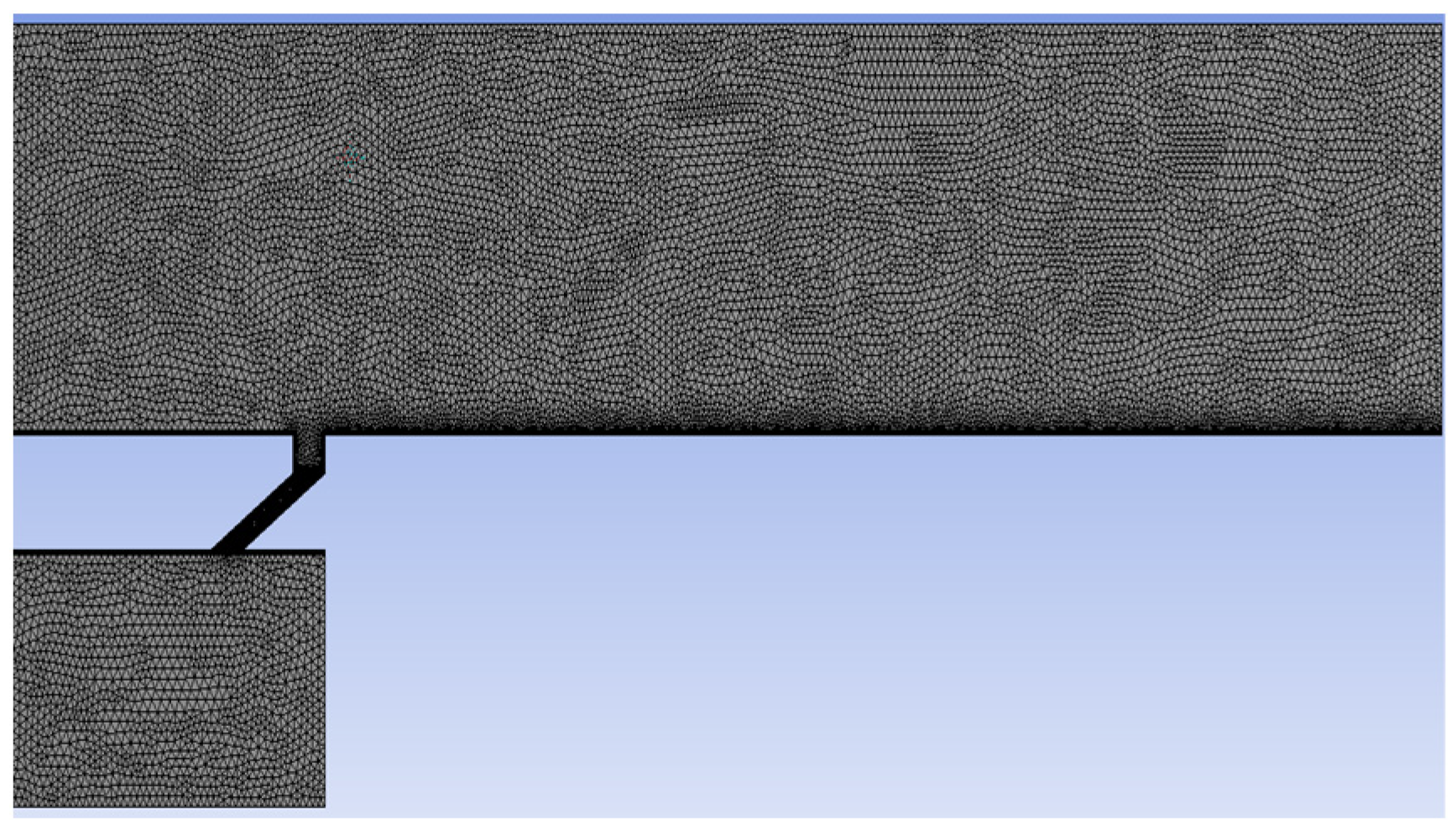
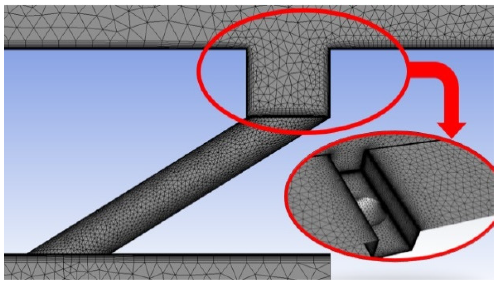
2.1. Flow Field Domain and Grid
Figure 1 shows the physical model of the computational domain. The axial, normal, and spreading (X × Y × Z) dimensions of the main flow channel are 45 D × 8 D × 3 D, and the axial, normal, and spreading (X × Y × Z) dimensions of the compressor are 10 D × 5 D × 3 D. The ramjet only works effectively once the vehicle reaches a certain flight speed, and the compressor is added to the model to provide a steady stream of continuous coolant to the main flow channel. The origin of the coordinates is set at the center of the intersection line between the exit of the transverse channel and the wall in the exit direction. Also, to reduce the influence of the outlet environment on the fluid near the gas film orifice, the distance between the orifice and the transverse mainstream inlet along the X direction is set to 9 D.
Figure 1.
Schematic diagram of the physical model in the computing domain.
The schematic diagrams of the film aperture and transverse groove models are shown in Figure 2. The details of film hole and transverse groove are film hole length L/D = 3.0, film hole incidence angle α = 30°, transverse groove depth H/D = 0.75, transverse groove width W/D = 1.0, and film hole spacing S/D = 3.0, respectively.
Figure 2.
Model diagram of film hole and transverse groove.
The gird structure diagram is shown in Figure 3 and Figure 4, using both tetrahedral mesh and structural mesh. Since the focus of this study is the cooling film on the wall surface. The structural mesh is chosen to be used in two places: the bottom surface of the main flow channel, i.e., the wall surface where the cooling film is mainly generated, and the upper wall surface of the compressor.
Figure 3.
Front view of the mesh model.
Figure 4.
Encrypted grid diagram of transverse grooves.
The y+ value of the boundary layer is about 1 to meet the requirement of the enhanced wall function, which can simulate the flow heat transfer process more accurately. The other areas in the flow field are divided using the tetrahedral mesh method. Due to the complexity of the flow near the gas film hole and the exit of the transverse groove, the locations near the gas film hole and near the boundary of the transverse groove are locally encrypted.
2.2. Governing Equation and Turbulence Model
In this study, the fluid in the flow field in the film cooling channel is treated as an incompressible fluid, and its control equations are simplified to the incompressible Navier-Stokes equations. In addition, mass, momentum, and energy are conserved and assumed. The Realizable k-ε model is chosen for the turbulence model with reference to the numerical simulations performed by Zhang et al. [42]. The volume of fluid (VOF) model is chosen to simulate two different gas incidences due to the different densities of the mainstream and the coolant. The interface between multiple mutually incompatible fluids can be obtained by the VOF model, which is more adapted to the present conditions.
2.3. Parameter Definition
The blowing ratio is the key thermal parameter affecting the performance of film cooling, which is defined as Equation (1):
where ρ is the fluid density, u is the fluid velocity, and the subscripts “c” and “m” indicate the coolant and the mainstream.
For the density ratio is defined as Equation (2):
where ρc is the density of the coolant, and ρm is the density of the mainstream, respectively.
Cooling efficiency is one of the important indicators to evaluate the performance of film cooling, and its calculation formula is as Equation (3):
where Tm is the mainstream temperature, Tc is the coolant temperature, and Tp is the wall temperature.
In addition, the Average Film Cooling Efficiency (AFCE) is the average along the Z-direction, which is obtained by Equation (4).
The area-averaged film cooling efficiency is also defined as the average cooling efficiency over the entire wall, which can be used directly to measure the cooling performance and is calculated as Equation (5).
2.4. Boundary Condition
The numerical simulations refer to the study of Zhang et al. [42] for the boundary condition settings, as shown in Table 1. The BR is calculated based on the main flow velocity and the average velocity at the hole entrance and is between 0.5 and 2.0. The boundary of the whole model is the adiabatic wall boundary under non-slip conditions. The outlet is a pressure outlet of 1 atmosphere. The sidewall surface of the main flow channel is set as a periodic boundary condition, which is due to the fact that in practical engineering situations, the gas film holes are often present in multiple side-by-side rows. A pressure-based solver is used, using the steady calculation method, and the residual level is set to less than 10−3 for all calculated cases.
Table 1.
Boundary condition setting of calculation domain.
2.5. Accuracy Verification
The numerical results of the average film cooling efficiency in this study are compared with Lu et al. [28] and Zhang et al. [42] to verify the accuracy of the method. The details of Zhang’s parameter settings are shown in Table 2, and it can be observed that the parameter settings in this study are the same as theirs. Figure 5 shows the results of the three numerical simulations when BR = 1.0, and the results show that the three fitted curves are in good agreement. Therefore, the physical model and calculation method used in this study is proved to be accurate for the next study.
Table 2.
Parameter setting.
Figure 5.
Algorithm accuracy verification results [28,42].
2.6. Modified Orthogonal Design of Experiments Method
A comprehensive study of the effect of four levels of four different parameters on the film cooling efficiency using the controlled variable method requires 44 = 256 experiments, which is a huge workload to complete [43]. Therefore, this study employs a modified orthogonal experimental design method to select two typical film cooling structures for investigation: flat plate film cooling and transverse groove film cooling. The selection process is outlined in the following procedure. This method can help us to select representative cases to lower the number of test cases.
- Controllable influence parameters, as well as output characteristic values, are determined;
- The table of levels of the parameters and the orthogonal table of the parameter design are determined;
- By numerical simulation, the average film cooling efficiency is calculated for each operating condition;
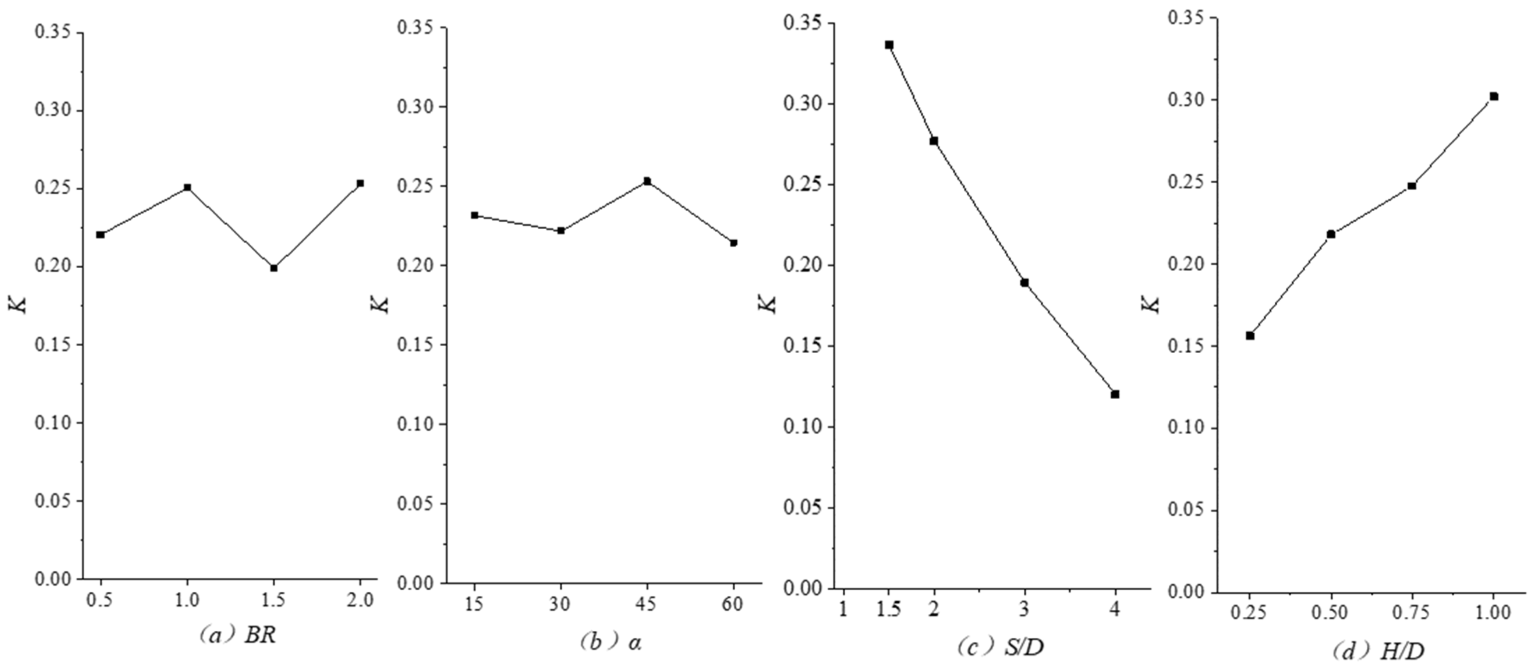
- The average of each level of each parameter is analyzed, denoted as Kij.
- The extreme difference of each parameter, denoted as Rj, is calculated by Equation (6). The contribution rate CRj is calculated by Equation (7);
- The optimal combination is determined (noted as optim-case): the three parameters determined by the three Kj,max is selected to form the optim-case.
3. Results and Discussion
3.1. Design of Numerical Simulation Parameter
3.1.1. Flat Plate Film Cooling
A modified orthogonal design of the experiment’s method is used to design the experiments for flat plate film cooling. The film cooling efficiency under the influence of three parameters, namely BR, α, and S/D, is analyzed. The experimental design process is as follows:
- BR, α, and S/D were identified as controllable influencing parameters with output characteristic values of ;
- Table 3 was identified as the level table of each parameter, and Table 4 was identified as the orthogonal table for the experimental parameter design;
Table 3. Simulation parameter level of flat plate film cooling.
Table 4. Orthogonal table of flat plate film cooling simulation. - The for each case was calculated by numerical simulation according to the parameter design table;
- The K value for each level of each parameter, the R-value for each parameter, and the CRj were calculated separately;
- The optimal combination is determined (optim-case).
The principle of the design of the simulation scheme using orthogonal tables is that each level of each factor is combined only once with any one level of another remaining factor in a group of 16 cases. For example, there are four combinations of BR = 0.5 selected in the 16 sets of cases, and the α and S/D parameters selected in these four cases must correspond to the levels of four different α and S/D. The number of numerical calculations can be reduced by using the modified orthogonal experimental method. Table 4 shows the L16 orthogonal table and the calculated results.
The value of K is the average of the calculated results for each parameter at each level. That is, Kij is the average of the of all four cases that take the parameter in row i and column j of the level table. For example, K32 of flat plate film cooling simulation is the average of the of case3, case7, case11, and case15, i.e., the four cases with α = 45° among the 16 cases. Due to the design principle of the orthogonal table, the 12 Kij exactly correspond to the parameters in Table 3 one by one. Therefore, we can predict the trend of the factor at the four levels by the trend of the Kij value in the same column. For example, the trend of BR can be predicted by K11, K12, K13, and K14.
The extreme difference of each parameter, denoted as Rj, is calculated by Equation (6). where Kj,max represents the maximum value of K1j, K2j, K3j, and K4j. Similarly, Kj,min represents the minimum value of K1j, K2j, K3j, and K4j. R indicates the difference between the maximum and minimum values, and the degree of influence of each parameter on the results can be judged according to the value of R.
Comparing the of 16 cases, case16 is the best, and case10 is the worst. Case16 is 21.68 times better than case10 from Table 4. The CR magnitudes of the three parameters calculated from Equation (7) are ranked as S/D > α > BR. From the values of the contributions, it can be concluded that there is the greatest influence on the cooling efficiency of the flat plate film for S/D, and BR and α have a smaller influence.
Figure 6 shows the trend of K for the three parameters. The results show that the K decreases with increasing BR as well as S/D. When α > 30°, the K increases with the increase of α. According to the selection principle of the parameters of the optim-case, the values of each parameter of the optim-case are BR = 0.5, α = 60°, and S/D = 1.5 in the study range of this study.
Figure 6.
Variation trend of K under three different parameters.
3.1.2. Transverse Groove Film Cooling
In the simulation of film cooling with transverse slots, there are four parameters that affect its cooling efficiency, namely BR, α, S/D, and H/D. The simulation scheme design process is basically the same as that of flat plate film cooling in Section 3.1.1.
Table 5 was identified as the level table of each parameter, and Table 6 was identified as the orthogonal table for the experimental parameter design.
Table 5.
Simulation parameter level of film cooling with a transverse groove.
Table 6.
Orthogonal table of film cooling simulation with transverse groove.
Table 6 shows the results of the L16 orthogonal table and calculations. Case14 has the best , and case10 has the worst . Case14 is 8.5 times better than case10. By comparing R with CR, it is concluded that there is a stronger influence on film cooling efficiency with transverse grooves for hole spacing and transverse groove depth and blowing ratio and incidence angle have a weaker influence on film cooling efficiency.
The four parameters ranked the magnitude of CR on : S/D > H/D > BR > α. This is different from the ranking of the contribution of flat plate film cooling. There is the least effect on the film cooling efficiency for the incidence angle. The presence of the transverse groove has a “blocking” effect on the injected coolant, so the effect of the incidence angle is weakened. Summarizing the above studies, it is concluded that the structural parameters of the transverse groove contribute much more to the cooling efficiency of the gas film than the coolant-related parameters.
Figure 7 represents the trend of K for different parameters. The results show that the K values decrease with increasing hole spacing and increase with increasing transverse groove depth. According to the selection principle of the parameters of the optim-case, the values of each parameter of the optim-case are taken as BR = 2.0, α = 45°, S/D = 1.5, and H/D = 1.0 within the research range of this study.
Figure 7.
Variation trend of K under four different parameters.
3.2. Flat Plate Film Cooling
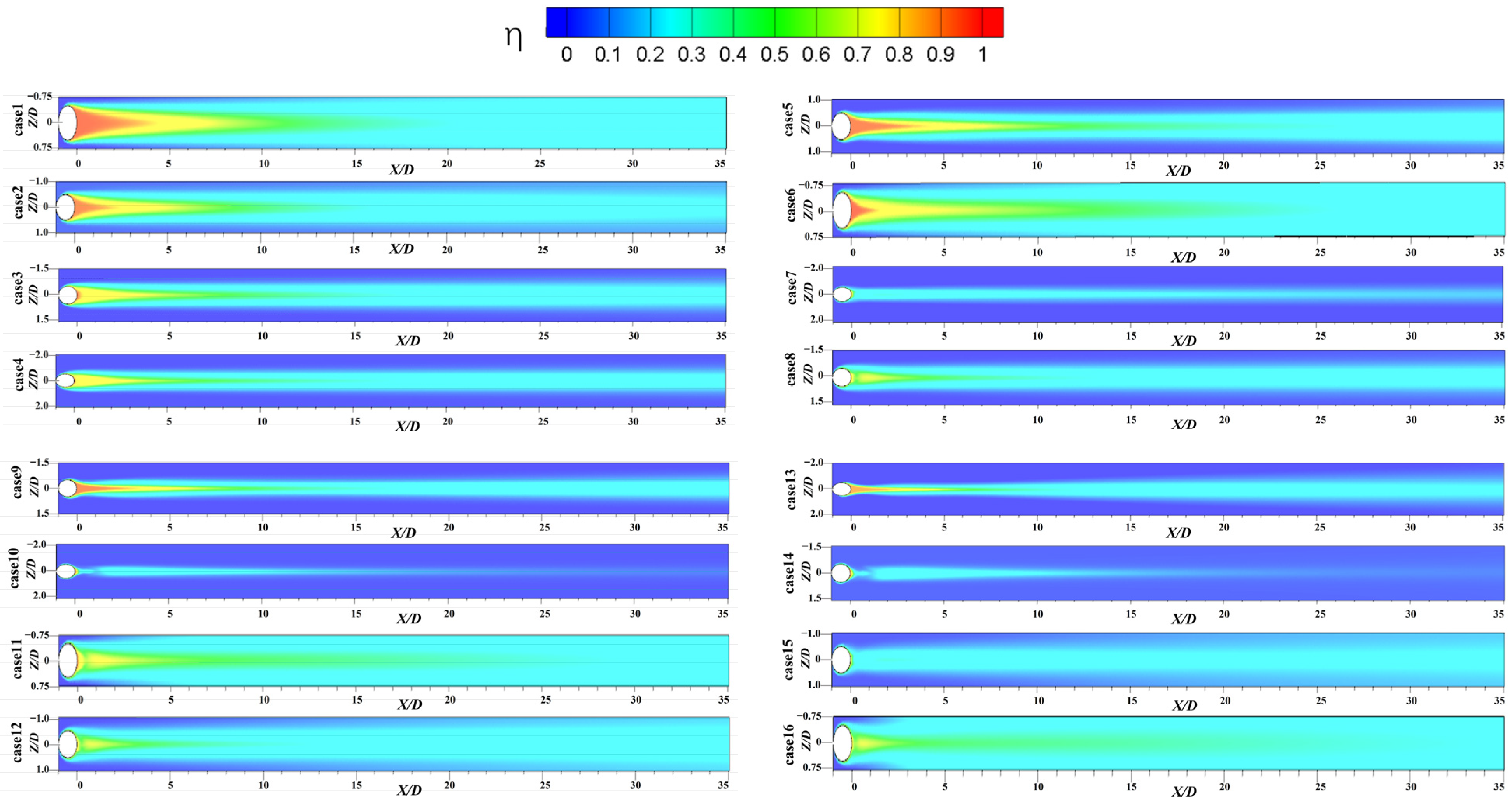
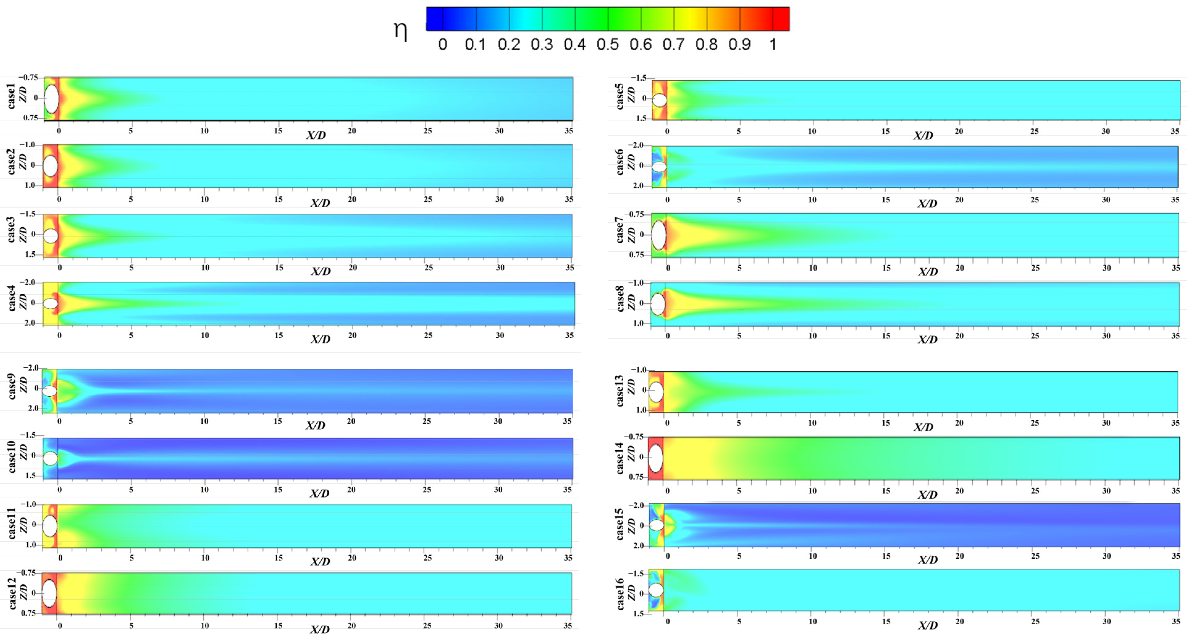
3.2.1. Display of Film Cooling Efficiency Results
Figure 8 shows the film cooling efficiency contour of the XY section with Z/D = 0 for 16 cases, which can be divided into two categories. If the area of the wall with a cooling efficiency greater than 0.2 is 70% or more, it is in the first category; otherwise, it is classified in the second category.
Figure 8.
Contours of flat plate film cooling efficiency.
The first category is case1, case2, case6, case11, case12, case15, and case16, a more complete film on the cooling wall surface is generated among all of which basically. The common point of the first category is that the hole spacing S/D = 1.5 or S/D = 2.0. the second category is case3, case4, case5, case7, case8, case9, case10, case13, case14. This group of cases only appears as a striped film on the wall surface and does not completely cover the wall surface. The common point is that, except for case5, the hole spacing is S/D = 3.0 or S/D = 4.0. Therefore, it can be found that there is the most intuitive effect on the cooling of the flat film for the hole spacing. When designing the ramjet, the film hole spacing should be less than 2.0 to prevent breakage due to overheating on the wall.
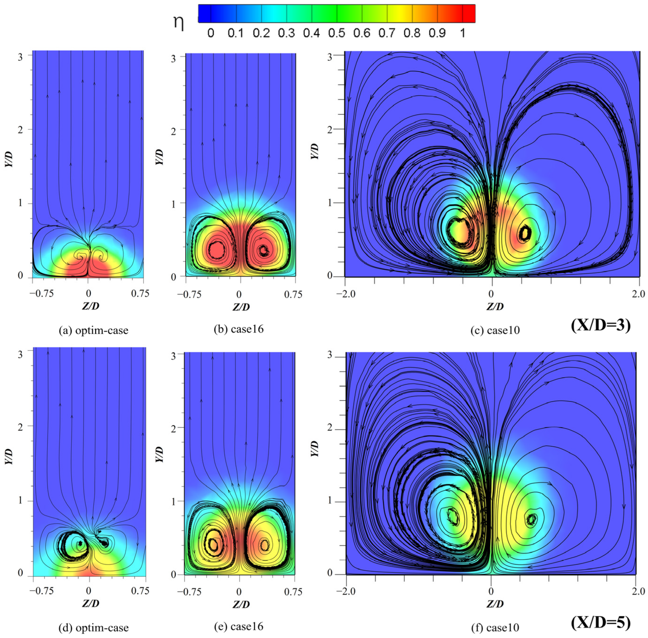
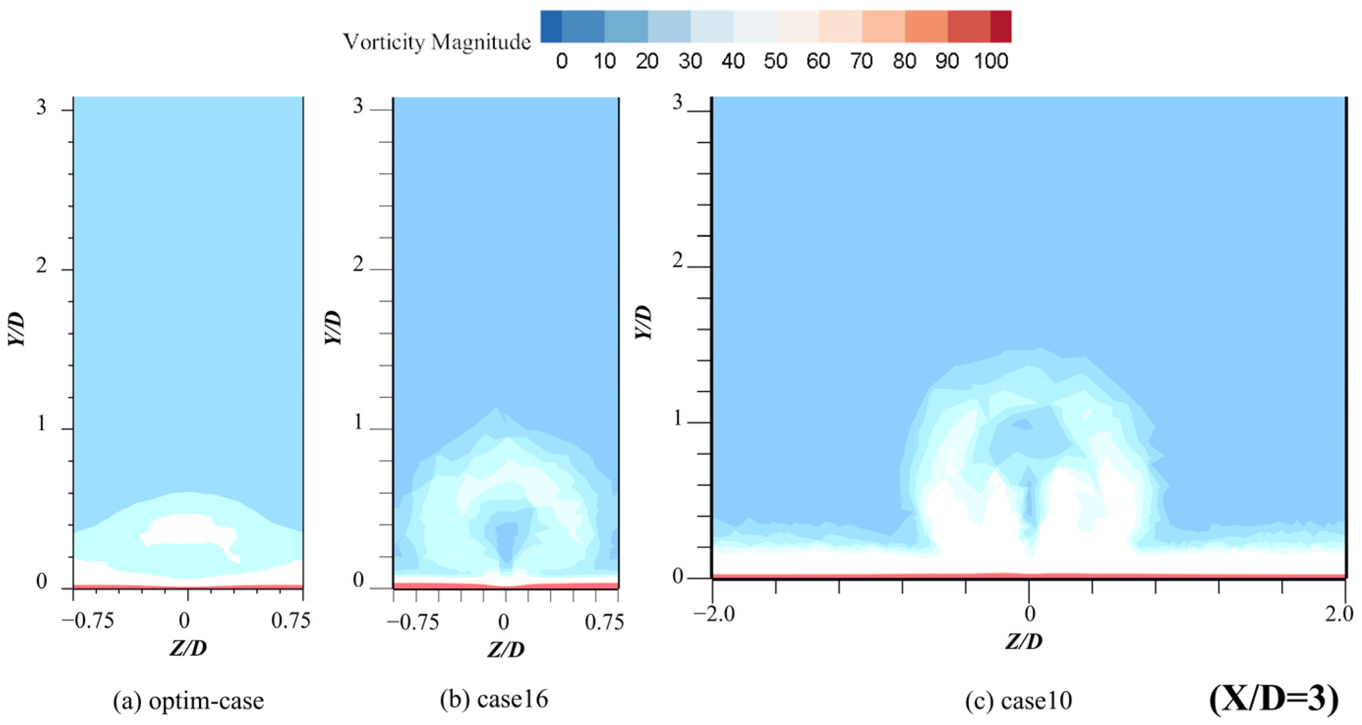
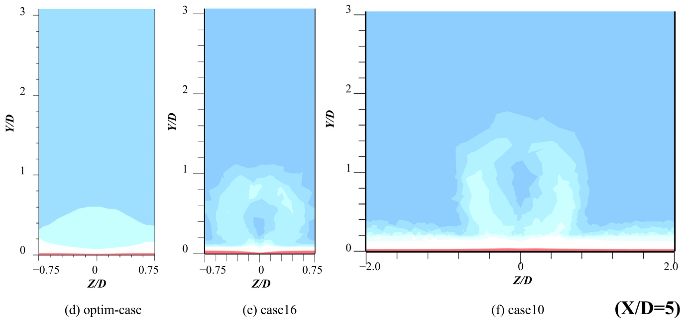
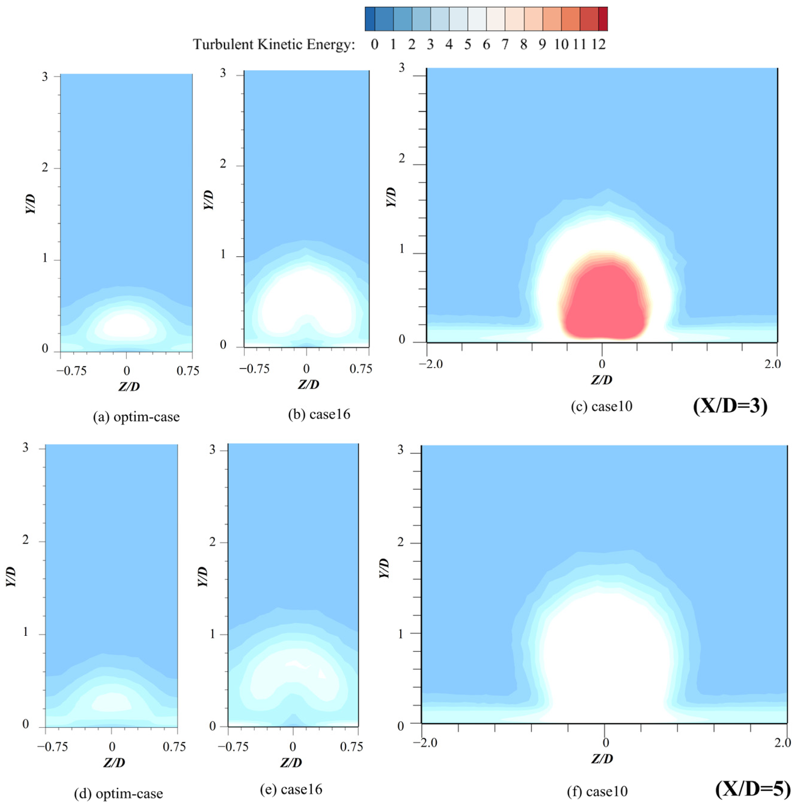
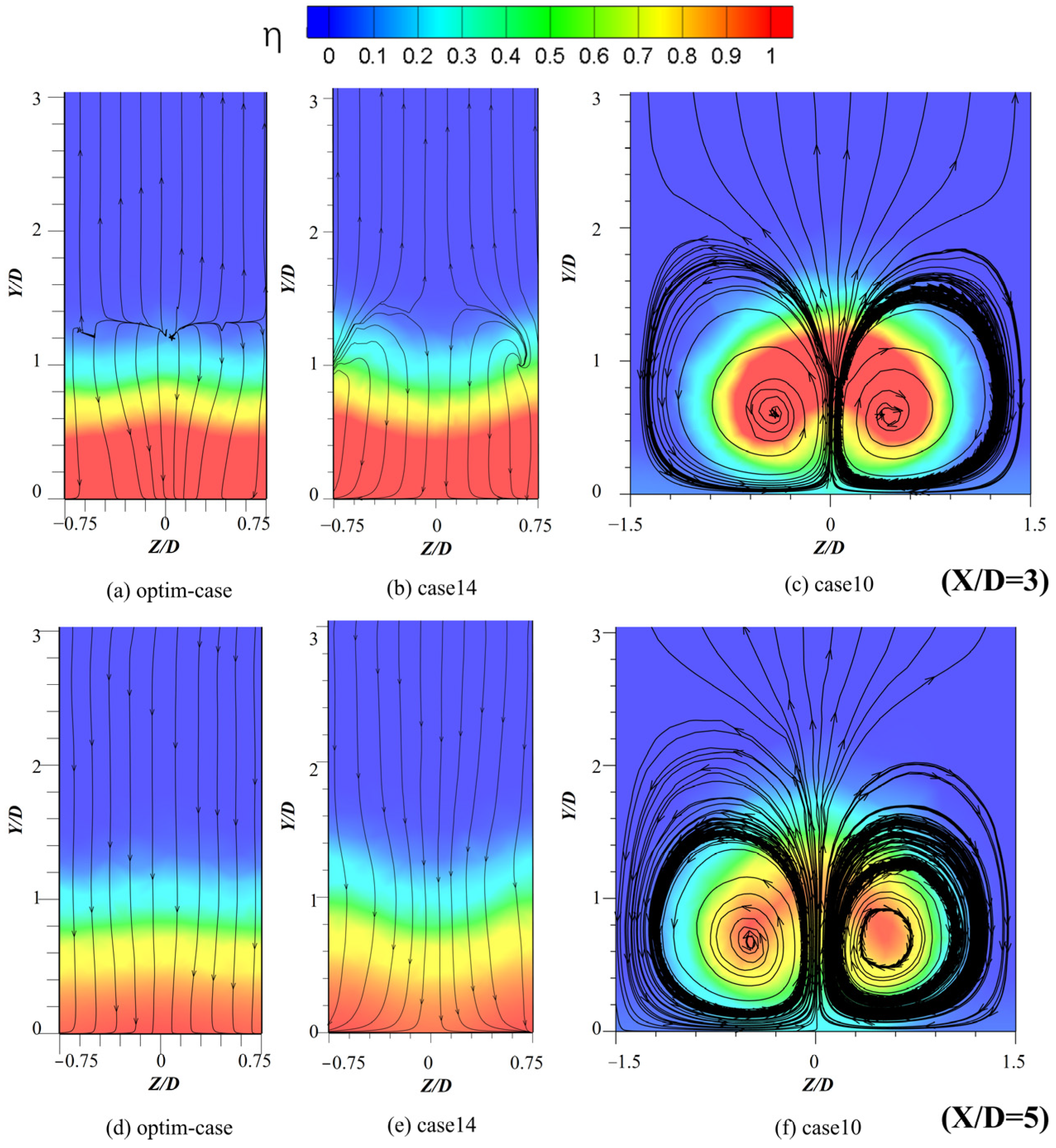
3.2.2. Flow Field Structure Analysis
The flow field cases of optim-case are derived by numerical simulation, and the flow field structures of these three special cases (optim-case, case16, and case10) are compared to analyze the cooling mechanism of flat plate film cooling. From Table 7, it can be seen that the magnitude of for the three cases is ranked as case16 > optim-case > case10. Thus, the optim-case that takes each parameter individually to the optimal level yields is not necessarily the case with the highest . It is further proved that the parameters affect each other.
Table 7.
Comparison of area average film cooling efficiency for flat plate film cooling.
Figure 9, Figure 10 and Figure 11 show the streamline diagrams, the vorticity diagrams, and the turbulent kinetic energy diagram of the YZ section with X/D = 3 and X/D = 5 for the three special cases of flat plate film cooling. From Figure 9, it can be seen that a CRVP is generated in all three cases, but the flow field affected by the vortex rings is not the same, and the largest affected area appears in the flow field of case10.
Figure 9.
Streamline diagram of YZ section with X/D = 3 and X/D = 5 for flat plate film cooling.

Figure 10.
Vorticity diagram of YZ section with X/D = 3 and X/D = 5 for flat plate film cooling.
Figure 11.
Turbulent kinetic energy diagram of YZ section with X/D = 3 and X/D = 5 for flat plate film cooling.
From Figure 10 and Figure 11, we find that case10 produces a much larger CRVP than the remaining two cases. And case10 has the worst cooling efficiency, which indicates that CRVP is the most important factor affecting the film cooling efficiency. Comparing the vorticity and turbulent kinetic energy of case16 and optim-case, most of the regions affected by CRVP in both are below Y/D = 1, so they have better efficiency.
The center region of Z/D = 0 in case16 is hardly affected by the vortex ring, and the region of Y/D = 0 is less affected by the vortex ring as the flow field develops. Compared to the optim-case, case16 has a greater ability to diffuse the air film over the entire wall. We predict a reason why the of case16 is greater than that of the optim-case.
Analyzing the contour of the YZ section for X/D = 3 and X/D = 5, we found that both the vortex volume and the turbulent kinetic energy are gradually smaller with the X direction. Since the X-direction is the main flow direction of the flow field, this means that the turbulent kinetic energy of the flow field is gradually dissipated as the flow field develops. Therefore, it can be concluded that as the flow field develops, the effect of CRVP is gradually weakened, and the cooling film is more likely to diffuse laterally in the region where X/D is larger.
3.3. Transverse Groove Film Cooling
3.3.1. Display of Film Cooling Efficiency Results
Figure 12 shows the XZ plane film cooling efficiency contours for 16 cases. The overall analysis of the 16 cases can be divided into three categories. The first category is the 10 cases with a protective film formed on the whole wall surface, including case1, case2, case5, case7, case8, case11, case12, case13, case14, and case16. The film cooling efficiency is uniform in the downstream region of X, which reaches 0.2 and above. The best ductility of Case14 in the X and Z direction can be clearly observed.
Figure 12.
Contours of film cooling efficiency with transverse grooves.
The second type is the three cases with a “strip-like film” on the wall, including case3, case4, and case6. This “strip-like film” is characterized by high efficiency in the middle and low efficiency on both sides along the Z-direction, similar to the strip-like film. Case4 is the most typical case. The third type of cases formed striped gas film, including case9, case10, and case15. In the center line of the Z-direction, a strip-shaped film is generated, while the sides are basically not covered by the film. Its film cooling efficiency is lower than other cases, and the degree of protection for the wall is poor, and it can only produce protection for the central region.
Comparing the second and third types of cases, the following conclusions can be obtained. As BR is small, the cooling jet can still extend in the Z-direction, and a film with low cooling efficiency will be formed on both sides. While BR is larger, the ductility of the cooling jet in the Z-direction is weakened, and there will still be a large momentum in the normal direction. This leads to the fact that only the central area on the wall is covered, while the sides are largely unprotected. Comparing the film-cooling efficiency contours of the two structures, it can be found that the film-cooling structure with transverse grooves outperforms the flat film-cooling structure in most cases.
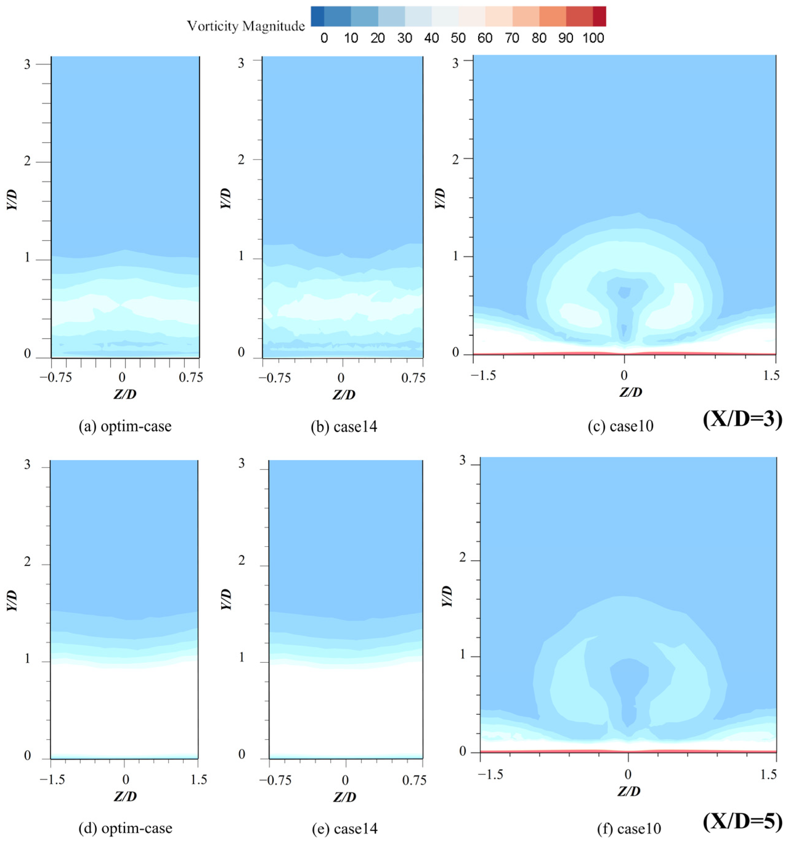
3.3.2. Flow Field Structure Analysis
This section analyzes the cooling mechanism of film cooling with transverse grooves by comparing the flow field structures of three special cases (optim-case, case14, case10). Firstly, the flow field of the optim-case is obtained through numerical simulation, and the cooling mechanism of film cooling with transverse grooves is analyzed by comparing three special cases. It can be seen from Table 8 that the cooling efficiency of the three cases is ranked as optim-case > case14 > case10. Here, the optim-case is obtained by taking the optimal level of each parameter separately. This is the case with the optimal cooling efficiency, which is different from the conclusion obtained in Section 3.2.2. The optim-case that takes each parameter individually to the optimal level yields is not the case with the highest in Section 3.2.2.
Table 8.
Comparison of area average film cooling efficiency for transverse groove film cooling.
Figure 13, Figure 14 and Figure 15 show the streamline diagrams, the vorticity diagrams, and the turbulent kinetic energy diagram of the YZ section with X/D = 3 and X/D = 5. Firstly, it is obvious that the CRVP is generated in case10, which causes the coolant in case10 to be “sucked” in the central area, while the walls on both sides are basically uncovered. Because of the presence of CRVP, the film cooling efficiency is the lowest. On the contrary, the vorticity and turbulent kinetic energy of both the optim-case and case14 are more uniformly distributed in the Z-direction, and the flow lines are basically uniformly distributed along the opposite direction of the Y-direction. The cooling jets are better adsorbed on the wall surface, resulting in higher cooling efficiency.
Figure 13.
Streamline diagram of YZ section with X/D = 3 and X/D = 5 for transverse groove film cooling.
Figure 14.
Vorticity diagram of YZ section with X/D = 3 and X/D = 5 for transverse groove film cooling.

Figure 15.
Turbulent Kinetic Energy of YZ section with X/D = 3 and X/D = 5 for transverse groove film cooling.
Further comparison of the vorticity diagrams and turbulent kinetic energy diagram of case14 and optim-case shows that there is a greater range of action in the Y-direction for the vorticity in case14. This indicates that the normal momentum of the cooling jet in case14 is greater and is more likely to break away from the wall compared to the optim-case. Such is the reason why the of the optim-case is slightly higher than that of case14.
4. Conclusions
Flat plates and air film cooling with transverse slots are tentatively attempted in ramjet. Due to the low velocity setting of the mainstream, it may provide a reference for the design of the preburner chamber in ramjet. By using an improved orthogonal experimental design approach, the numerical simulation process is optimized and the number of computational cases is reduced. The following conclusions are drawn.
- By comparing the K, R, and CR of each parameter, it is concluded that in flat plate film cooling, the magnitude of the contribution of three parameters to the efficiency of flat plate film cooling is ranked as S/D > α > BR. At transverse groove film cooling, the magnitude of the contribution of four parameters to the efficiency of gas film cooling is ranked as S/D > H/D > BR > α;
- When flat plate film cooling is adopted, and the wall hole spacing is S/D > 2.0, a strip of film will be formed on the wall, which will cause the metal wall surface to overheat. When using transverse groove film cooling for larger S/D, the cooling jet can still expand in the Z-direction when the BR is small, and a less efficient film is formed on both sides. When the BR is large, both sides of the wall are basically unprotected;
- Comparing the film cooling efficiency contours of the two structures, it can be found that a more complete film in most cases in the transverse groove film cooling is generated, which is better than the flat plate film cooling;
- By analyzing and comparing the Streamline diagrams and Vorticity diagrams of the YZ cross-section, it can be obtained that CRVP is the most important factor affecting the film cooling efficiency. Without CRVP, in the case where the influence range of the vortex in the normal direction is larger, the cooling flow will be more likely to break away from the wall, resulting in a lower film cooling efficiency.
Author Contributions
X.D. (First Author): Conceptualization, Data curation, Formal analysis, Methodology, Software, Investigation, Formal Analysis, Writing—Original Draft; J.C.: (Corresponding author): Supervision, Methodology, Writing—Original Draft; G.C.: Project administration, Funding acquisition, Resources; T.L.: Resources, Validation; H.M.: Software, Visualization. All authors have read and agreed to the published version of the manuscript.
Funding
This research was funded by the National Natural Science Foundation of China grant number [U2141246].
Data Availability Statement
The data used to support the findings of this study are available from the corresponding author (changjianlong1989@126.com) upon request.
Conflicts of Interest
The authors declare that there are no conflicts of interest regarding the publication of this paper.
Nomenclature
| AFCE | Average Film Cooling Efficiency |
| BR | Blowing ratio |
| CR | Contribution rate |
| CRVP | Counter-rotating vortex pair |
| D | Hole diameter |
| DR | Density ratio |
| FCE | Film Cooling efficiency |
| H/D | Transverse groove depth |
| K | The average of each level of each parameter |
| L/D | Film hole length |
| R | The extreme difference of each parameter |
| S/D | Film hole spacing |
| T | Temperature |
| u | Flow velocity |
| VOF | Volume of Fluid |
| W/D | Transverse groove width |
| X | Positive direction of flow |
| Y | Normal flow direction |
| Z | Lateral flow direction |
| α | Angle of incidence |
| Fluid density | |
| The area-averaged film cooling efficiency |
References
- Fry, R.S. A Century of Ramjet Propulsion Technology Evolution. J. Propuls. Power 2004, 20, 27–58. [Google Scholar] [CrossRef]
- Hewitt, P. Status of Ramjet Programs in the United States. In Proceedings of the 44th AIAA/ASME/SAE/ASEE Joint Propulsion Conference & Exhibit, Hartford, CT, USA, 21–23 July 2008; American Institute of Aeronautics and Astronautics: Reston, VA, USA, 2008. [Google Scholar]
- Ma, W.; Yin, Z.; Pan, C.; Li, B.; Zhang, H. Thermodynamics Cycle Analysis of a One-Dimensional Scramjet Model in Different Combustion Modes. In Proceedings of the 21st AIAA International Space Planes and Hypersonics Technologies Conference; American Institute of Aeronautics and Astronautics, Xiamen, China, 6 March 2017; American Institute of Aeronautics and Astronautics: Reston, VA, USA, 2017. [Google Scholar]
- Roux, J.; Tiruveedula, L. Constant Velocity Combustion Scramjet Cycle Analysis for Non-Ideal Mass Flow Rate. Therm. Sci. Eng. Prog. 2017, 2, 8–14. [Google Scholar] [CrossRef]
- Wang, J.; Wen, Y.; Zha, B.; Xu, Z.; Zhang, T. Effects of the Air Inlet Angle on the Combustion and Ablation Environment of a Hybrid Powder-Solid Ramjet. Int. J. Aerosp. Eng. 2022, 2022, 8091927. [Google Scholar] [CrossRef]
- Jing, T.; Xu, Z.; Xu, J.; Qin, F.; He, G.; Liu, B. Characteristics of Gaseous Film Cooling with Hydrocarbon Fuel in Supersonic Combustion Chamber. Acta Astronaut. 2022, 190, 74–82. [Google Scholar] [CrossRef]
- Kanda, T.; Masuya, G.; Ono, F.; Wakamatsu, Y. Effect of Film Cooling/Regenerative Cooling on Scramjet Engine Performances. J. Propuls. Power 1994, 10, 618–624. [Google Scholar] [CrossRef]
- Park, K.H.; Yang, K.M.; Lee, K.W.; Cho, H.H.; Ham, H.C.; Hwang, K.Y. Effects of Injection Type on Slot Film Cooling for a Ramjet Combustor. J. Mech. Sci. Technol. 2009, 23, 1852–1857. [Google Scholar] [CrossRef]
- Zhang, T.; Zhao, H.; He, L.; Wang, T. Study on the Combustion Process of the Ramjet Combustion Chamber. J. Phys. Conf. Ser. 2023, 2489, 012010. [Google Scholar] [CrossRef]
- Mahoney, J. Inlets for Supersonic Missiles; AIAA Education Series; American Institute of Aeronautics and Astronautics: Reston, VA, USA, 1990. [Google Scholar]
- Oh, J.Y.; Ma, F.; Hsieh, S.-Y.; Yang, V. Interactions between Shock and Acoustic Waves in a Supersonic Inlet Diffuser. J. Propuls. Power 2005, 21, 3. [Google Scholar] [CrossRef]
- Chang, J.; Duan, X.; Du, Y.; Guo, B.; Pan, Y. Investigations on the Effect of Different Influencing Factors on Film Cooling Effectiveness under the Injection of Synthetic Coolant. Sci. Rep. 2021, 11, 3408. [Google Scholar] [CrossRef]
- Bontempo, R.; Manna, M. Work and Efficiency Optimization of Advanced Gas Turbine Cycles. Energy Convers. Manag. 2019, 195, 1255–1279. [Google Scholar] [CrossRef]
- Masci, R.; Sciubba, E. A Lumped Thermodynamic Model of Gas Turbine Blade Cooling: Prediction of First-Stage Blades Temperature and Cooling Flow Rates. J. Energy Resour. Technol. 2018, 140, 020901. [Google Scholar] [CrossRef]
- Khalatov, A.; Shi-Ju, E.; Wang, D.; Borisov, I. Film Cooling Evaluation of a Single Array of Triangular Craters. Int. J. Heat Mass Transf. 2020, 159, 120055. [Google Scholar] [CrossRef]
- Hou, R.; Wen, F.; Luo, Y.; Tang, X.; Wang, S. Large Eddy Simulation of Film Cooling Flow from Round and Trenched Holes. Int. J. Heat Mass Transf. 2019, 144, 118631. [Google Scholar] [CrossRef]
- Chang, J.; Du, Y.; Zheng, S.; Duan, X.; Liu, Y. Performance Analysis of Different Influencing Factors on Film Cooling and the Internal Relations with Vortex Structures. AIP Adv. 2019, 9, 070701. [Google Scholar] [CrossRef]
- Bunker, R.S.; Bailey, J.C.; Lee, C.; Abuaf, N. Method for Improving the Cooling Effectiveness of a Gaseous Coolant Stream, and Related Articles of Manufacture. U.S. Patent 6234755 B1, 22 May 2001. [Google Scholar]
- Wei, J.; Zhu, H.; Liu, C.; Song, H.; Liu, C.; Meng, T. Experimental Study on the Film Cooling Characteristics of the Cylindrical Holes Embedded in Sine-Wave Shaped Trench. J. Eng. Gas Turbines Power 2016. [Google Scholar] [CrossRef]
- Waye, S.; Bogard, D. High-Resolution Film Cooling Effectiveness Measurements of Axial Holes Embedded in a Transverse Trench With Various Trench Configurations. J. Turbomach.-Trans. ASME 2007, 129, 294–302. [Google Scholar] [CrossRef]
- Li, J.; Ren, J.; Jiang, H. Film Cooling Performance of the Embedded Holes in Trenches with Compound Angles. In Proceedings of the Volume 4: Heat Transfer, Parts A and B, Glasgow, UK, 10 October 2010; pp. 1415–1424. [Google Scholar]
- Lu, Y.; Nasir, H.; Ekkad, S.V. Film Cooling From a Row of Holes Embedded in Transverse Slots. In Proceedings of the Volume 3: Turbo Expo 2005, Parts A and B, Reno, NV, USA, 1 January 2005; pp. 585–592. [Google Scholar]
- Bunker, R.S. Film Cooling Effectiveness Due to Discrete Holes Within a Transverse Surface Slot. In Turbo Expo: Power for Land, Sea, and Air; American Society of Mechanical Engineers Digital Collection: Amsterdam, The Netherlands, 2009; pp. 129–138. [Google Scholar]
- Lee, K.-D.; Kim, K.-Y. Surrogate Based Optimization of a Laidback Fan-Shaped Hole for Film-Cooling. Int. J. Heat Fluid Flow 2011, 32, 226–238. [Google Scholar] [CrossRef]
- Wang, C.; Zhang, J.; Zhou, J. Optimization of a Fan-Shaped Hole to Improve Film Cooling Performance by RBF Neural Network and Genetic Algorithm. Aerosp. Sci. Technol. 2016, 58, 18–25. [Google Scholar] [CrossRef]
- Yang, X.; Liu, Z.; Feng, Z. Numerical Evaluation of Novel Shaped Holes for Enhancing Film Cooling Performance. J. Heat Transf. 2015, 137, 071701. [Google Scholar] [CrossRef]
- Wei, H.; Zu, Y.Q.; Ai, J.L.; Ding, L. Experimental Study on the Full-Coverage Film Cooling of Fan-Shaped Holes with a Constant Exit Width. Int. J. Heat Mass Transf. 2019, 140, 379–398. [Google Scholar] [CrossRef]
- Lu, Y.; Dhungel, A.; Ekkad, S.; Bunker, R. Film Cooling Measurements for Cratered Cylindrical Inclined Holes. J. Turbomach.-Trans. ASME 2009, 131, 011005. [Google Scholar] [CrossRef]
- Cao, N.; Li, X.; Wu, Z.; Luo, X. Effect of Film Hole Geometry and Blowing Ratio on Film Cooling Performance. Appl. Therm. Eng. 2020, 165, 114578. [Google Scholar] [CrossRef]
- Maiteh, B.Y.; Jubran, B.A. Effects of Pressure Gradient on Film Cooling Effectiveness from Two Rows of Simple and Compound Angle Holes in Combination. Energy Convers. Manag. 2004, 45, 1457–1469. [Google Scholar] [CrossRef]
- Ahn, J.; Sung Jung, I.; Lee, J.S. Film Cooling from Two Rows of Holes with Opposite Orientation Angles: Injectant Behavior and Adiabatic Film Cooling Effectiveness. Int. J. Heat Fluid Flow 2003, 24, 91–99. [Google Scholar] [CrossRef]
- Bashir, M.H.; Shiau, C.-C.; Han, J.-C. Film Cooling Effectiveness for Three-Row Compound Angle Hole Design on Flat Plate Using PSP Technique. Int. J. Heat Mass Transf. 2017, 115, 918–929. [Google Scholar] [CrossRef]
- Bunker, R.S. A Review of Shaped Hole Turbine Film-Cooling Technology. J. Heat Transf. 2005, 127, 441–453. [Google Scholar] [CrossRef]
- Fan, X.; Du, C.; Li, L.; Li, S. Numerical Simulation on Effects of Film Hole Geometry and Mass Flow on Vortex Cooling Behavior for Gas Turbine Blade Leading Edge. Appl. Therm. Eng. 2017, 112, 472–483. [Google Scholar] [CrossRef]
- Oliver, T.A.; Bogard, D.G.; Moser, R.D. Large Eddy Simulation of Compressible, Shaped-Hole Film Cooling. Int. J. Heat Mass Transf. 2019, 140, 498–517. [Google Scholar] [CrossRef]
- Zuo, W.; Jiaqiang, E.; Liu, X.; Peng, Q.; Deng, Y.; Zhu, H. Orthogonal Experimental Design and Fuzzy Grey Relational Analysis for Emitter Efficiency of the Micro-Cylindrical Combustor with a Step. Appl. Therm. Eng. 2016, 103, 945–951. [Google Scholar] [CrossRef]
- Jiaqiang, E.; Han, D.; Qiu, A.; Zhu, H.; Deng, Y.; Chen, J.; Zhao, X.; Zuo, W.; Wang, H.; Chen, J.; et al. Orthogonal Experimental Design of Liquid-Cooling Structure on the Cooling Effect of a Liquid-Cooled Battery Thermal Management System. Appl. Therm. Eng. 2018, 132, 508–520. [Google Scholar] [CrossRef]
- Su, L.; Zhang, J.; Wang, C.; Zhang, Y.; Li, Z.; Song, Y.; Jin, T.; Ma, Z. Identifying Main Factors of Capacity Fading in Lithium Ion Cells Using Orthogonal Design of Experiments. Appl. Energy 2016, 163, 201–210. [Google Scholar] [CrossRef]
- Ji, L.; Si, Y.; Liu, H.; Song, X.; Zhu, W.; Zhu, A. Application of Orthogonal Experimental Design in Synthesis of Mesoporous Bioactive Glass. Microporous Mesoporous Mater. 2014, 184, 122–126. [Google Scholar] [CrossRef]
- Shan, W.; Wu, L.; Tao, N.; Chen, Y.; Guo, D. Optimization Method for Green SrAl2O4: Eu2+, Dy3+ Phosphors Synthesized via Co-Precipitation Route Assisted by Microwave Irradiation Using Orthogonal Experimental Design. Ceram. Int. 2015, 41, 15034–15040. [Google Scholar] [CrossRef]
- Yang, P.; Tan, X.; Sun, H.; Chen, D.; Li, C. Fire Accident Reconstruction Based on LES Field Model by Using Orthogonal Experimental Design Method. Adv. Eng. Softw. 2011, 42, 954–962. [Google Scholar] [CrossRef]
- Zhang, R.; Zhou, L.; Xing, J.; Luo, C.; Du, X. Numerical Evaluation of Film Cooling Performance of Transverse Trenched Holes with Shaped Lips. Int. Commun. Heat Mass Transf. 2021, 125, 105326. [Google Scholar] [CrossRef]
- Wang, J.; Liu, C.; Zhao, Z.; Baleta, J.; Sundén, B. Effect and Optimization of Backward Hole Parameters on Film Cooling Performance by Taguchi Method. Energy Convers. Manag. 2020, 214, 112809. [Google Scholar] [CrossRef]
Disclaimer/Publisher’s Note: The statements, opinions and data contained in all publications are solely those of the individual author(s) and contributor(s) and not of MDPI and/or the editor(s). MDPI and/or the editor(s) disclaim responsibility for any injury to people or property resulting from any ideas, methods, instructions or products referred to in the content. |
© 2024 by the authors. Licensee MDPI, Basel, Switzerland. This article is an open access article distributed under the terms and conditions of the Creative Commons Attribution (CC BY) license (https://creativecommons.org/licenses/by/4.0/).