Article

Research on the Motion and Dynamic Characteristics of the Hose-and-Drogue System under Bow Wave

1
Faculty of Electronic and Information Engineering, Xi’an Jiaotong University, Xi’an 710049, China
2
Theory Training Department, Harbin Air Force Flight Academy, Harbin 150001, China
3
School of Aerospace Engineering, Xi’an Jiaotong University, Xi’an 710049, China
*
Author to whom correspondence should be addressed.
Aerospace 2024, 11(1), 13; https://doi.org/10.3390/aerospace11010013
Submission received: 26 November 2023 / Revised: 19 December 2023 / Accepted: 20 December 2023 / Published: 23 December 2023
(This article belongs to the Section Aeronautics)

Abstract

:
To study the hose-and-drogue system’s motion under bow waves, this paper established a dynamic model of the hose-and-drogue system based on the multibody dynamics theory and the rigid ball-and-rod model. The wake of a tanker aircraft was taken into account in the simulation. The simulation results conformed to the general laws and verified the model’s accuracy. The equilibrium positions of the hose-and-drogue system were computed by the linear superposition of the bow waves and wake. The motion of the hose-and-drogue system was simulated and analyzed when a receiver aircraft moved at a constant speed or accelerated relative to the tanker aircraft. Since the receiver aircraft would not immediately stop after docking, the pulling force changes on the hose with and without a reel were compared. The present results are essential for improving the success rate of aerial refueling and ensuring the safety and stability of the hose-and-drogue system.

1. Introduction

In recent years, unmanned system technology has developed rapidly, especially unmanned aerial vehicles (UAVs). However, the flight range of UAVs has always been an essential factor restricting their application. With the development of aerial refueling, UAVs can greatly extend the flight range. Aerial refueling is divided into two main methods: boom-and-nozzle and hose-and-drogue aerial refueling [1,2]. Compared to boom–nozzle aerial refueling, hose-and-drogue aerial refueling boasts several advantages, including a simple structure, lower technical complexity, and the ability to refuel multiple UAVs simultaneously. Therefore, it is widely adopted in many countries. However, this method also has some shortcomings. For example, the hose is flexible, and hose-and-drogue aerial refueling is influenced by the external environment. The most obvious thing is that when the receiver aircraft is slowly docked relative to the refueling aircraft, the receiver aircraft will disturb the surrounding airflow, which will affect the balance of the hose-and-drogue system, causing the drogue to shift towards the side away from the receiver aircraft, which is very unfavorable for docking. Therefore, the bow wave has been an important influencing factor for the success of docking. Studying the motion and dynamic characteristics of the hose-and-drogue system under bow waves is very necessary.
There have been many works on aerial refueling, and the main methods involved include computational fluid dynamics (CFD), the multibody dynamics theory, and a combined method of the two. Although the results of CFD are relatively accurate, the computation time and cost are a little high [3,4]. This method mainly focuses on the equilibrium position of the hose. Since the aircraft structure is very complex, it is very complicated to study docking using CFD. To study the dynamic response of the hose-and-drogue system, some scholars adopted a combination of CFD and the multibody dynamics theory [5,6]. CFD was used to compute the wake of the tanker aircraft, and the multibody dynamics theory was used for modeling the hose-and-drogue system.
In some works, only mathematical theory was used to model the hose-and-drogue system and the related influencing factors. There were also significant differences in the model based on different assumptions. Starting from the force balance, [7] derived the position equation of the hose. By simplifying the computation, the docking position between the tanker aircraft and the receiver could be computed using a trapezoidal integral. Refs. [8,9] modeled the hose-and-drogue system in a two-dimensional plane, derived differential equations in the x and y directions, and transformed the equations into discrete forms suitable for a numerical solution. Ref. [10] proposed a method for modeling the hose using a three-node bending beam element based on finite elements. This method overcame the difficulties of the classical cable theory by treating large rotations and deformations of the refueling assembly. Ref. [11] proposed a method for simulating the hose using a structure connected by a rigid rod and a frictionless spherical joint. Compared to the abovementioned methods, this method ensured the results’ accuracy and fast computation speed. Therefore, the method was widely used. It was used to deeply study the motion of the hose-and-drogue system under the influence of the wake, atmospheric turbulence, and bow wave and active control of the hose-and-drogue system [12,13,14,15]. Moreover, [16,17,18,19,20] studied the whiplash phenomenon during aerial refueling. Ref. [21] analyzed the influence of hose bending moment on aerial refueling in a two-dimensional plane. Ref. [22] studied the dynamic characteristics of the hose during docking. However, these papers did not consider the bow wave. The bow wave is also an important factor, and there are few studies on bow wave modeling, such as the Rankine body model [23,24,25], the fitting Rankine body model [26], CFD [27], and so on.
The existing works in aerial refueling mainly focus on modeling the hose-and-drogue system and the motion of the hose-and-drogue system under different conditions. There are few efforts on the docking of aerial refueling. In the studies of the docking process, the influencing factors considered were not comprehensive enough, and the results obtained had limited guidance for aerial refueling. In addition, during docking, the pulling force received by the hose should be within a certain limit. Otherwise, even if docking is successful, when the pulling force of the hose is subjected to excessive pulling force, cracks or even fractures may occur, which can lead to aerial refueling failure. To solve these possible problems, the major contributions in this paper are in the following aspects.
(1) The effects of the wake and bow wave were comprehensively considered, and a linear superposition method was adopted for the computation. Due to the flexible characteristics of the hose, the bending restoring force was considered during modeling. Therefore, the model was much more accurate.
(2) To choose a suitable initial position for docking, the equilibrium positions of the hose-and-drogue system were analyzed when the receiver aircraft was located at different relative positions. Then, the motion laws of the hose-and-drogue system during docking were obtained.
(3) For the actual docking process, a deceleration model of the receiver aircraft was established after the successful docking. To reduce the pulling force of the hose, a reel model was applied for releasing and retracting the hose.
(4) An ingenious method was proposed to solve the two-end-constrained problems. The method considered the actual characteristics of the hose and could accurately obtain the motion of the hose.
The paper mainly includes four parts. Section 1 provides the background and current situation of the hose-and-drogue aerial refueling. Section 2 discusses the modeling process of the hose-and-drogue system and bow wave. Section 3 discusses the equilibrium positions of the hose-and-drogue system when the receiver aircraft was located at different relative positions and investigates the motion of the hose-and-drogue system during docking. At the same time, the section presents a deceleration model for the receiver aircraft and obtains the pulling force of the hose with or without a reel. The last section offers the conclusion.

2. Modeling

2.1. The Hose-and-Drogue System

According to the lumped parameter method, the hose was divided into n segments, and half of the mass sum of the adjacent segments on each node was concentrated on the node. In this way, the hose became a model of many ball-and-rod models with end-to-end connections. Assuming that the mass distribution of the hose was uniform, the gravity and aerodynamic forces of the hose were converted to the nodes. By analyzing the forces at each node, the dynamic model of the hose was established based on Newton’s second law.
Two coordinate systems are introduced herein. The horizon system OnXnYnZn is the inertial coordinate system, and the drag point system OwXwYwZw is the modeling reference system. The X-axis direction is the same as the tanker aircraft speed direction. The deflection angle of the K segment relative to the OwXwYw plane and OwXwZw plane is θk1 and θk2, and the model ignores the rotation of the hose around its axis.

2.1.1. Kinematic Analysis

As shown in Figure 1, it can be seen that in the OwXwYwZw coordinate system, the spatial position vector of the node K can be represented as follows.
r k = r k 1 + p k
where pk is the distance vector from node K − 1 to node K and rk is the distance vector from the drag point to node K.
In the OwXwYwZw coordinate system, pk can be represented by lk, θk1 and θk2.
p k = l k cos θ k 1 cos θ k 2 sin θ k 2 sin θ k 1 cos θ k 2 T
where lk represents the length of the K segment.
By taking the first and second derivatives of Equation (1), the velocity and acceleration of node K can be obtained.
v k = v k 1 + p ˙ k a k = a k 1 + p ¨ k
When the supporting point system rotates relative to the horizon system, the formulas for p ˙ k and p ¨ k are as follows.
p ˙ k = i = 1 2 p k , θ k i θ ˙ k i + p k , l k l ˙ k + ω × p k
p ¨ k = i = 1 2 p k , θ k i θ ¨ k i + p ˙ k , θ k i θ ˙ k i + p k , l k l ¨ k + p ˙ k , l k + α × p k + ω × p ˙ k
where p k , θ k i = p k / θ k i , p k = p k / l k , ω is the angular velocity of the drag point system relative to the horizon system, α is the angular acceleration of the drag point system relative to the horizon system, and l ˙ k and l ¨ k are the speed and acceleration for the hose release and retraction.
By multiplying p k , θ k i both sides of Equation (5) simultaneously and substituting Equation (3) into (5), one can obtain the second derivative of the azimuth angles of all the segments.
θ ¨ k i = p k , θ k i ( ( a k a k 1 j = 1 2 ( p ˙ k , θ k j θ ˙ k j ) ) p k , l k l ¨ k p ˙ k , l k l ˙ k ( α × p k ) ( ω × p ˙ k ) ) / ( p k , θ k i · p k , θ k i )
As long as the acceleration of each node is known, the Runge–Kutta method can be used to determine the motion law of the hose.

2.1.2. Dynamic Analysis

According to Newton’s second law, the acceleration of node K is as follows.
a k = Q k + t k t k + 1 m k
where tk is the pulling force of the K segment, mk is half of the sum of the mass of the K − 1 segment and the K segment of the hose, and Qk is the external force acting on node K.
The length of the hose meets the constraints p k · p k = l k 2 . Taking the second derivative of the equation, we can obtain the following.
p ˙ k × p ˙ k + p k × p ¨ k = l ˙ k 2 + l k l ¨ k
Define n k = n k / n k , then the following.
p k = l k n k p ˙ k = l ˙ k n k l k n ˙ k
Substitute Equations (3), (7) and (9) into Equation (8), and we can then obtain the motion equation of node K.
n k × n k 1 m k 1 t k 1 1 m k 1 + 1 m k t k + n k × n k + 1 m k t k + 1 = l ¨ k l k n ˙ k × n ˙ k Q k 1 m k 1 Q k m k × n k
The above equation is a recursive formula based on the order of nodes, which is extrapolated according to the nodes to obtain a linear equation system. The pulling force of each segment can be obtained by solving the equations.

2.1.3. External Force Analysis

The external forces acting on node K include gravity, aerodynamic forces, bending restoring forces, and pulling forces. By conducting a force analysis on node K, one can obtain the following.
Q k = m k g + R k + D k + D k + 1 / 2
When the hose is bent under force, a restoring moment will be generated inside the hose. The equivalent external force method was used to model the bending restoring force of the hose. The formula for the bending restoring force is as follows.
R k = 8 E I γ / l k 2
Here, E is the elastic modulus of the hose, I is the polar moment of inertia at the hose interface, and γ is the angle between two adjacent rods.
The formula for calculating the angle between two adjacent segments is given by the following.
γ = arccos p k × p k + 1 p k p k + 1
The direction of the force is the same as the following vector direction.
e R k = p k + 1 p k + 1 p k p k
The aerodynamic force consists of two parts: the frictional resistance along the axis of every segment and the pressure difference resistance perpendicular to the axis of every segment, which can be expressed as follows.
D k = D t , k + D n , k = 0.5 ρ v t , k 2 π d o l k c t , k n k + 0.5 ρ v n , k 2 d o l k c n , k v n , k v n , k
where vtk is the tangential component of the velocity of the K segment, vnk is the normal component of the velocity of the K segment, ρ is the air density, do is the outer diameter of the hose, and ct,k and cn,k are the tangential and normal aerodynamic drag coefficients of the K segment of the hose.
The force acting on the end node can be calculated according to the following equation.
Q N = m n + m drogue g + D N / 2 + D drouge
where mN is the average mass of the last segment of the hose, mdrogue is the mass of the drogue, and Ddrogue is the aerodynamic force acting on the drogue.
The formula for Ddrogue is given by the following.
D drouge = 0.5 ρ V N / air π d drouge 2 4 c drouge V N / air
where cdrogue is the resistance coefficient of the drogue, ddrogue is the diameter of the drogue, and V N , air is the velocity of the drogue relative to the air.

2.2. Bow Wave

When the receiver aircraft approaches the refueling aircraft, it will generate airflow movement at its head. When it approaches the drogue, the drogue will sway. The above phenomenon is called the bow wave effect [24]. There are many methods for establishing bow wave models, the Rankine body model is widely used in engineering. Moreover, in the actual docking, the movement area of the drogue is generally limited to the vicinity of the receiver aircraft’s nose, and the Rankine body model has a slight computational complexity and high accuracy. Therefore, this paper chose the Rankine body model to compute the velocity under the bow wave.
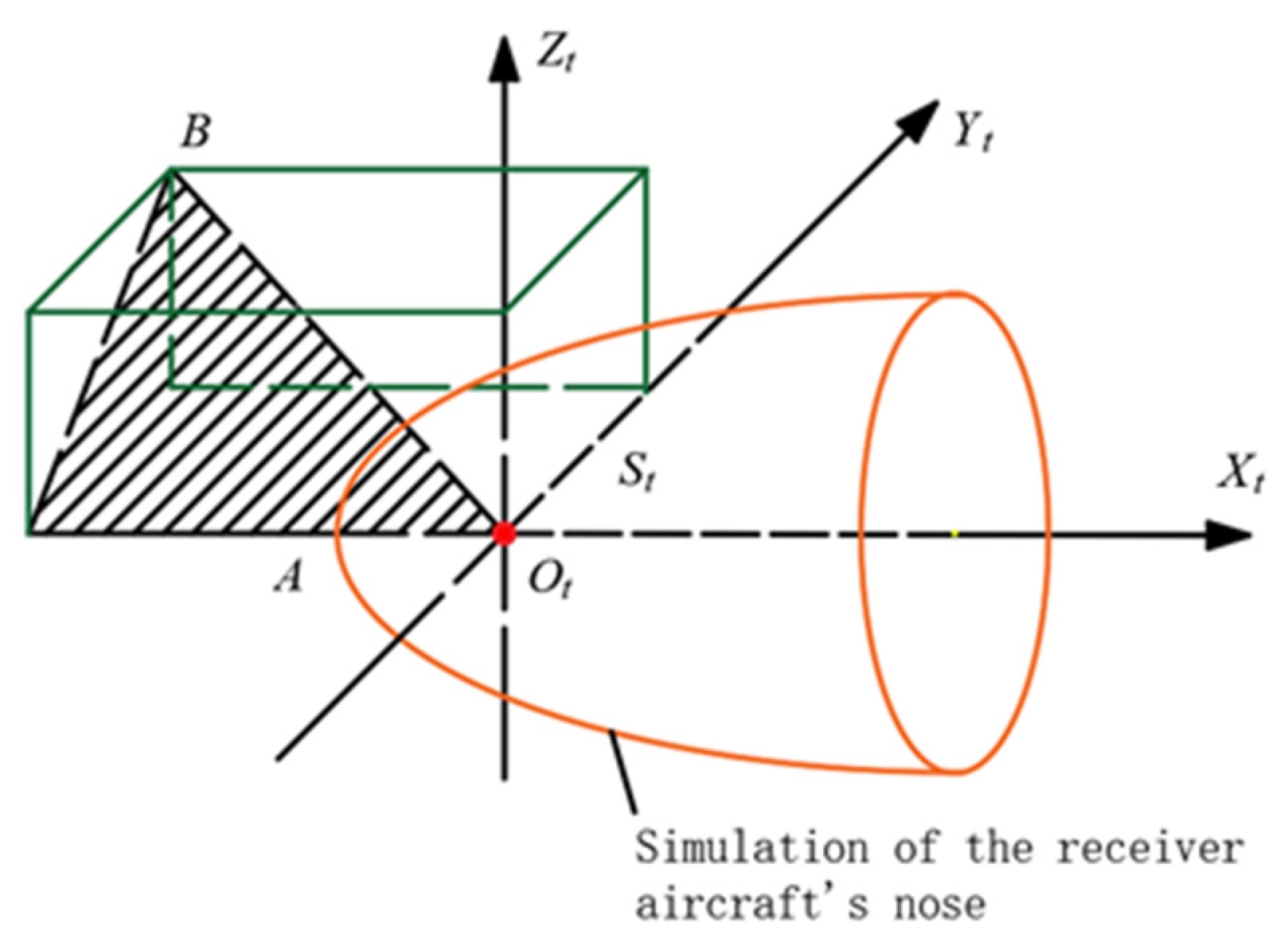
As shown in Figure 2, the coordinate system Ot-XtYtZt was established at first; the coordinate origin Ot was at the point source inside the nose, and OtXt was in the symmetry plane of the nose parallel to the axis of the nose and pointed to the rear of the receiver aircraft. OtYt was perpendicular to the symmetry plane of the nose and pointed to the right side of the aircraft, and OtZt constituted a Cartesian coordinate system with OtXt and OtYt. We assumed that B(x, y, z) was an arbitrary point in the space close to the receiver aircraft’s nose and ignored the angle of attack of the receiver aircraft. To solve the velocity at point B under the bow wave, a reference plane was established by using point B and the OtXt axis, and the two-dimensional flow theory was used to solve for the velocity of point B in this plane.
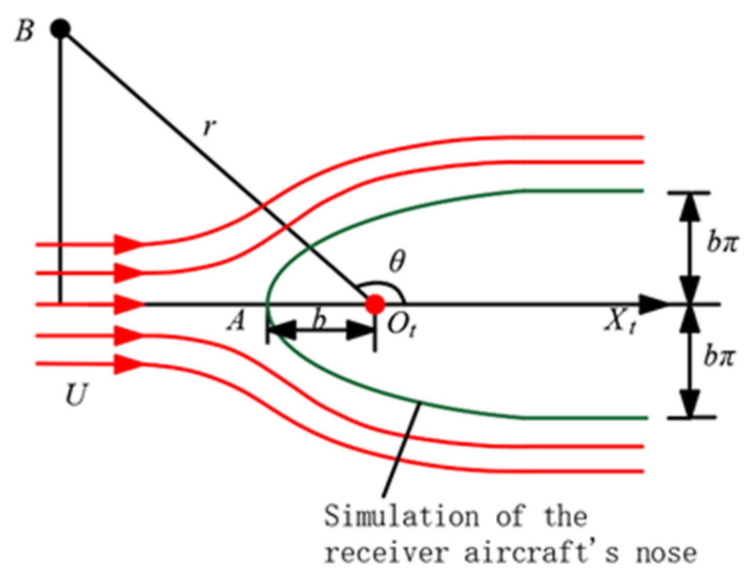
As shown in Figure 3, the Rankine body flow is a planar flow field formed by the superposition of a uniform flow along the OtXt direction and a point source of strength Qsource. The uniform flow velocity distribution is uniform, with parallel straight streamlines. The point source is the fluid that scatters uniformly from a particular center point to the surrounding areas. The fluid velocity is the same at the same radial distance from the point source. Since the streamlines cannot intersect, the Rankine body model divides the space into two parts through the streamline passing through the green streamline. The external flow field can be seen as a disturbance caused by placing an aircraft’s nose shaped like the green streamline into a uniform flow. Therefore, the Rankine body can model the receiver aircraft’s bow wave. The green streamline is the boundary of the receiver aircraft’s nose. The derivation process of the Rankine body model is as follows.
In the planar polar coordinate system, the stream functions for the uniform flow and the point source are as follows.
ψ 1 = U r sin θ
ψ 2 = Q s o u r c e 2 π θ
where ψ1 is the stream function of the uniform flow, ψ2 is the stream function of the point source, U is the flow velocity, r is the polar diameter, θ is the polar angle, and Qsource is the point source intensity.
According to the principle of stream function superposition, the stream function of the Rankine body flow is as follows.
ψ = ψ 1 + ψ 2 = U r sin θ + Q s o u r c e 2 π θ
The streamline equation for the two-dimensional flow is as follows.
v r r d θ v θ d r = 0
Since the Rankine body model satisfies the continuity equation, Equation (21) can be used as the total differential of the stream function.
d ψ = ψ r d r + ψ θ d θ = v θ d r + v r r d θ
It can be concluded that the radial velocity and circumferential velocity in polar coordinates are as follows.
v r = 1 r ψ θ = U cos θ + Q s o u r c e 2 π r
v θ = ψ r = U sin θ
The streamline equation of the Rankine body model is as follows.
ψ = U r sin θ + Q s o u r c e 2 π θ = C
Different streamlines can be obtained by taking different values for the constant C. There is a special point A in the flow field, where the velocity equals 0. It is similar to the apex of the receiver aircraft’s nose. Its coordinates are (−b, 0). When θ = π, it can be obtained as follows.
v r , θ = π = U + Q s o u r c e 2 π b = 0
Q s o u r c e = 2 π U b
The value of the stream function at point A is as follows.
ψ A , π = Q s o u r c e 2
The streamline equation passing through stagnation point A is as follows.
r = Q s o u r c e 2 π U π θ sin θ = b π θ sin θ
As θ tends to be 0 or 2π, the two streamlines are parallel to each other, and the distance from the OtXt axis is as follows.
H θ = 0 , 2 π = r sin θ = b π θ = ± b π
Therefore, b can be determined from the radius of the receiver aircraft’s nose.
b = R n o s e π
where Rnose is the radius of the receiver aircraft’s nose.
Therefore, as long as the radius of the receiver aircraft’s nose and the flight speed are known, the components vθ and vr of the bow wave velocity on the surface OtXtB can be computed at any point near the receiver aircraft’s nose.
The radial velocity vector and the circumferential velocity vector are decomposed into the X-axis and Y-axis.
v x = v r cos θ v θ sin θ v y = v r sin θ + v θ cos θ
The three-dimensional velocity component of any point B (x, y, z) in the Ot-XtYtZt coordinate system is as follows.
v b o w x = v x v b o w y = v y y y 2 + z 2 v b o w z = v y z y 2 + z 2
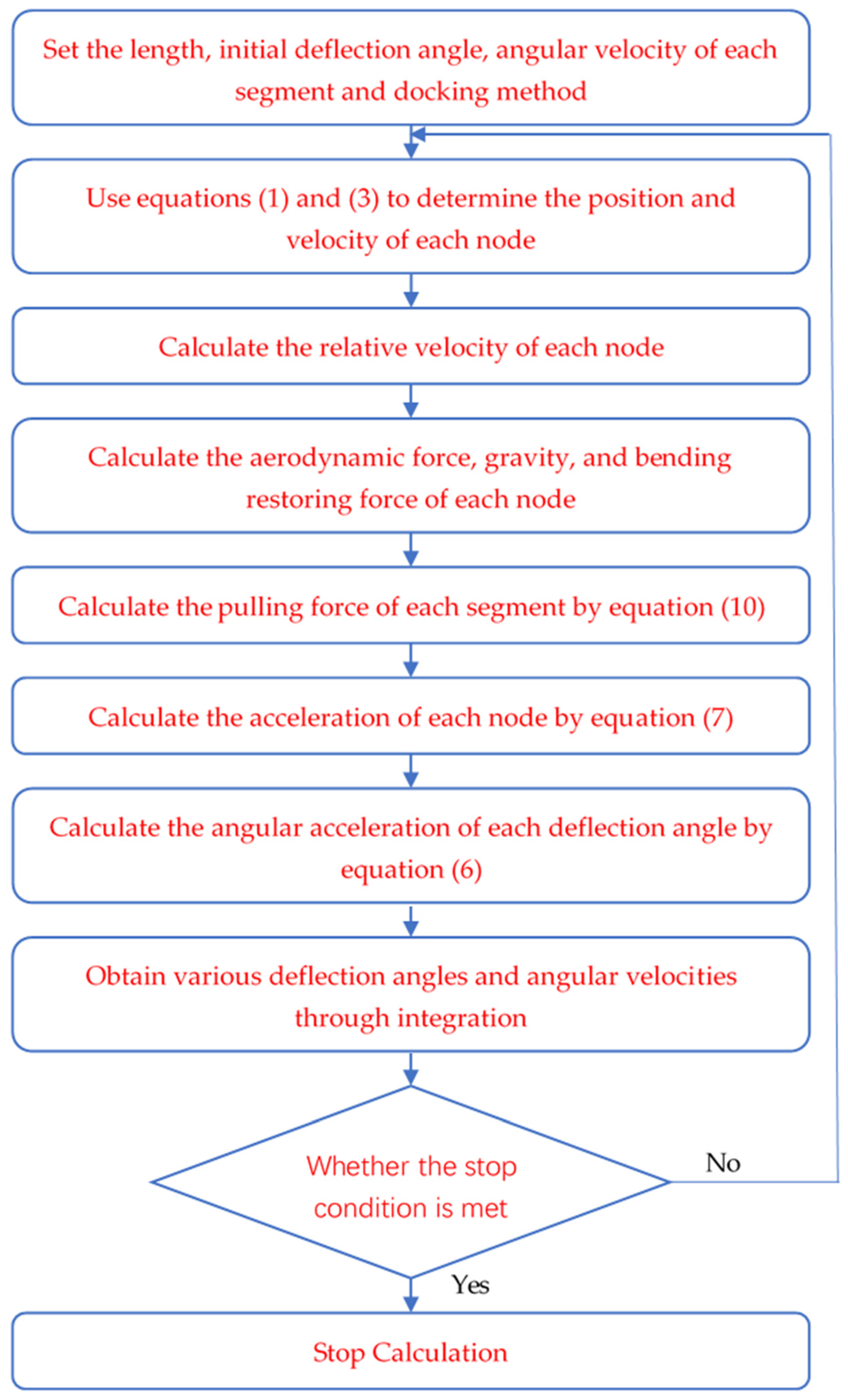
The whole calculation process is shown in Figure 4.

3. Numerical Simulation and Analysis

The simulation code was written in MATLAB. The simulation parameters in this paper are shown in Table 1.

3.1. Model Accuracy Verification

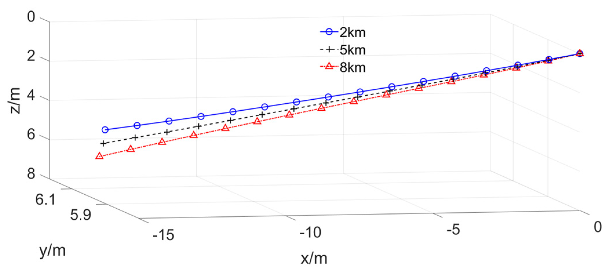
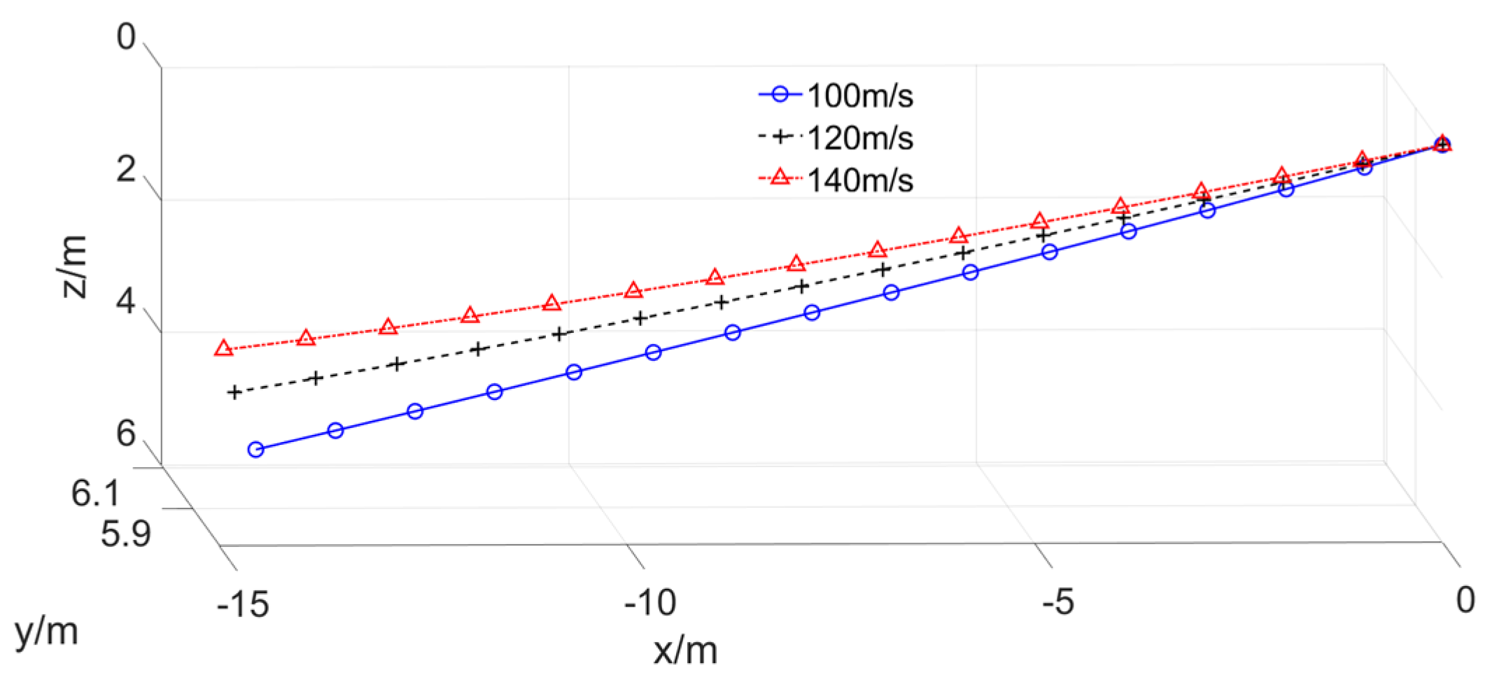
Figure 5 and Figure 6 show that at the same speed, as the altitude increased, the air density decreased, the resistance of the drogue decreased, and the sinking of the drogue increased. At the same altitude, as the flight speed increased, the drogue’s resistance increased, and the drogue’s sinking decreased. The above change trend was consistent with the flight test results, which indicated the model’s accuracy.

3.2. The Equilibrium Position of the Drogue under the Bow Wave

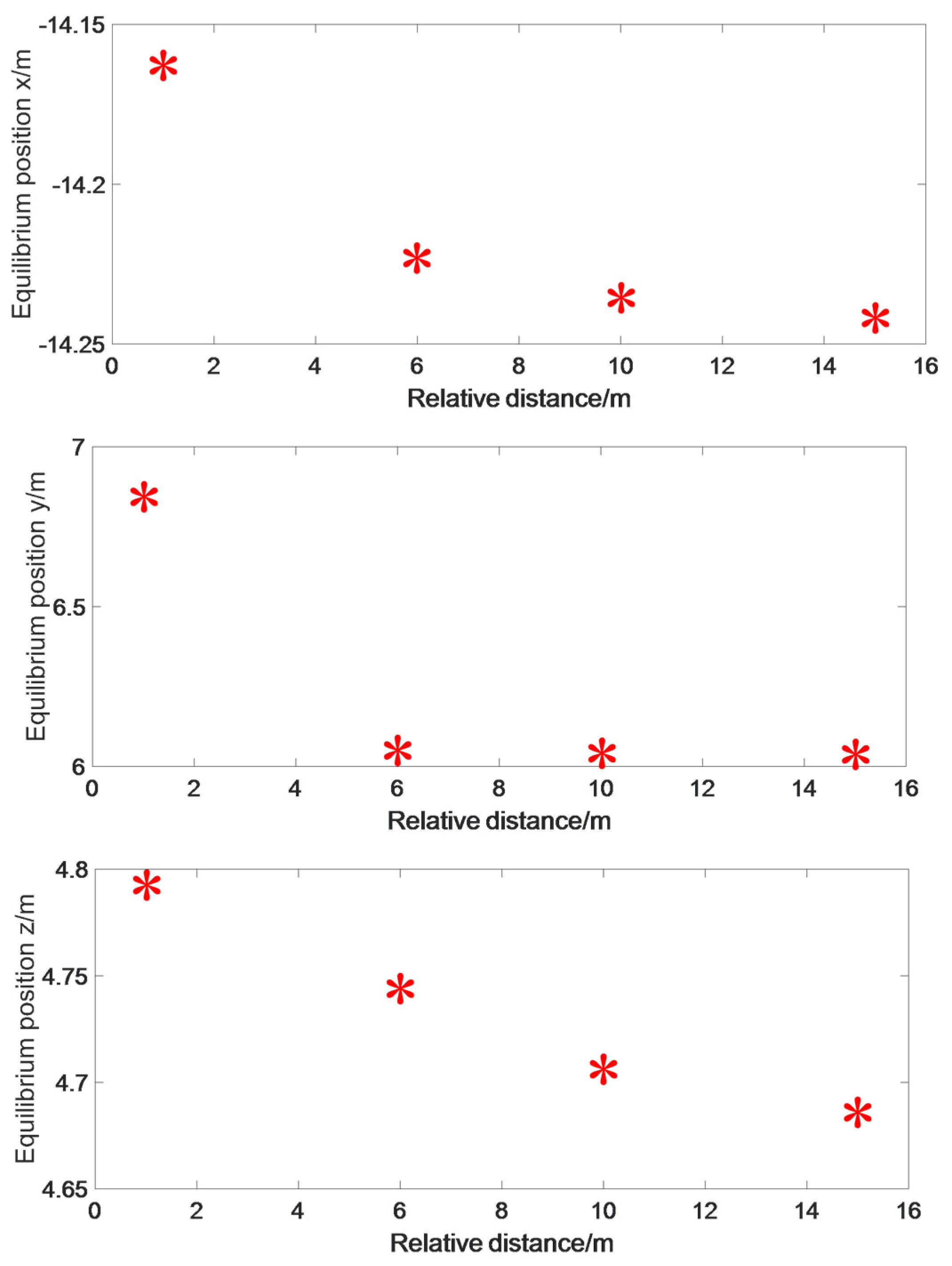
The flight speed was set to 120 m/s, the flight altitude was set to 5 km, and the longitudinal and transverse radii of the receiver’s nose were 0.6 m. Considering that the tanker and receiver aircraft flew at the same speed, the receiver aircraft were simulated at different relative positions. The equilibrium positions of the drogue are shown in Figure 5.
Figure 7 shows that as the receiver aircraft approached the tanker aircraft, the equilibrium positions of the drogue moved forward, rightward, and downward. At a distance of 15 m from the initial equilibrium position of the drogue, the impact of the receiver aircraft on the equilibrium of the hose-and-drogue system was very little.

3.3. Change of the Drogue When the Receiver Aircraft Approached at a Constant Speed

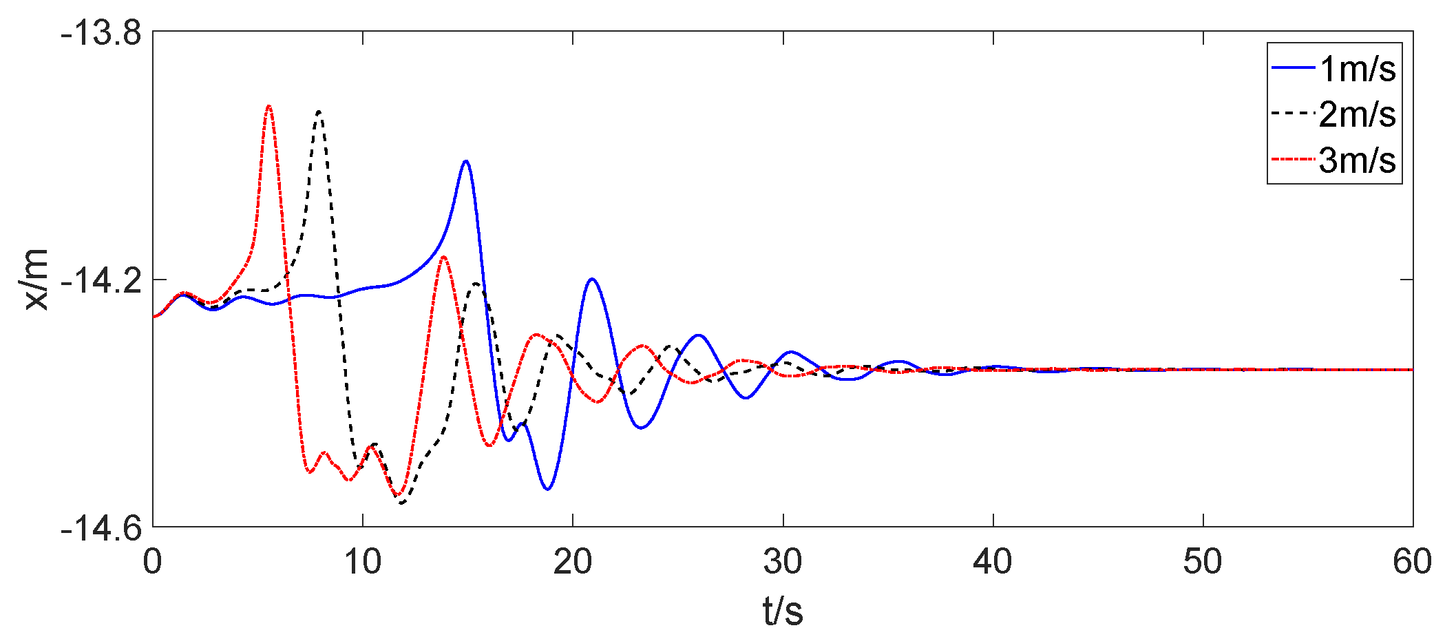
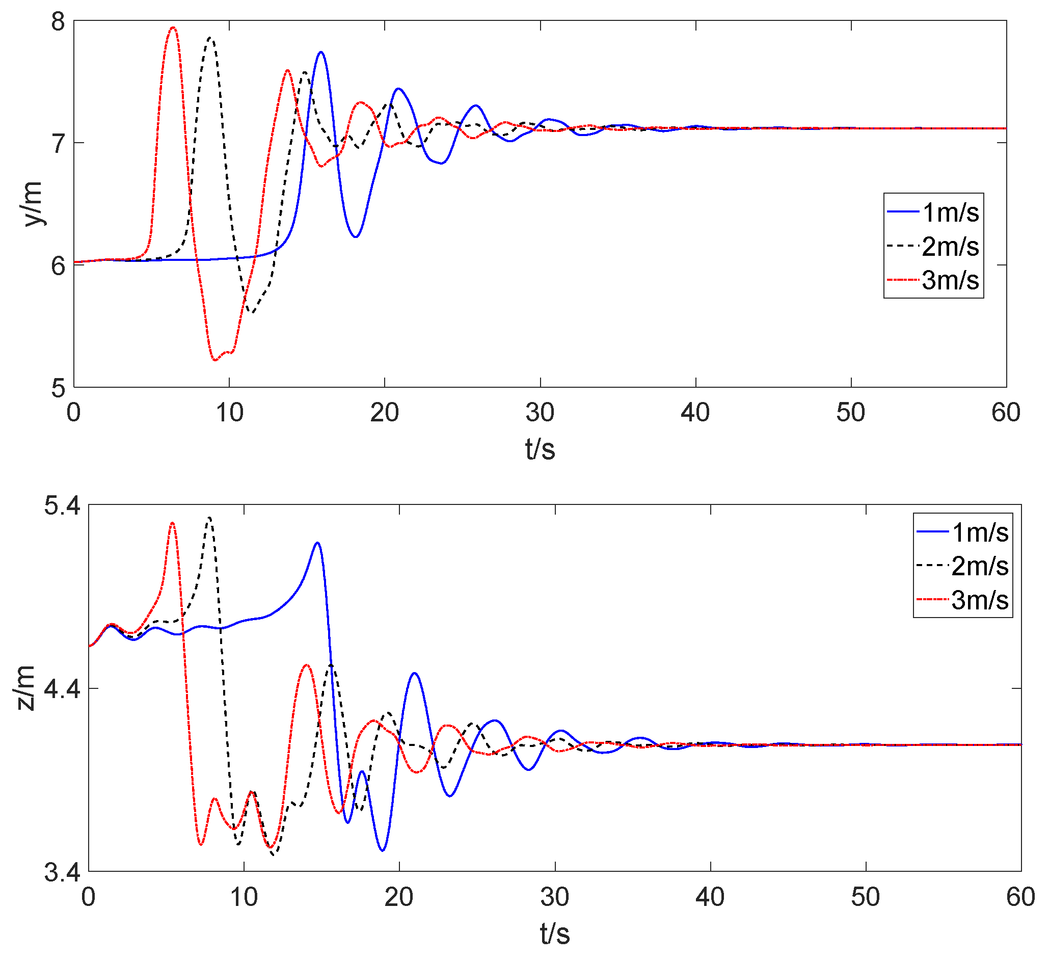
When the receiver aircraft docked with the tanker aircraft at a constant speed, the initial position of the receiver’s probe was 15 m directly behind the equilibrium position of the drogue. The spatial position changes of the drogue during docking are shown in Figure 6 when the relative speeds of the receiver aircraft to the tanker aircraft were 1 m/s, 2 m/s, and 3 m/s.
Figure 8 shows that when the docking was at a constant speed, as the receiver aircraft slowly approached the drogue, the drogue moved forward, downward, and rightward. When the receiver aircraft approached the initial position of the drogue, the movement of the drogue suddenly reversed, and the position changed rapidly. When the receiver aircraft reached the initial position of the drogue, it no longer moved relative to the tanker aircraft, and the drogue slowly balanced at a certain position. As the simulation conditions for the various situations were consistent, after the receiver aircraft reached the initial position of the drogue, the equilibrium positions were also consistent.

3.4. Change of the Drogue When the Receiver Aircraft Approached at a Uniform Acceleration

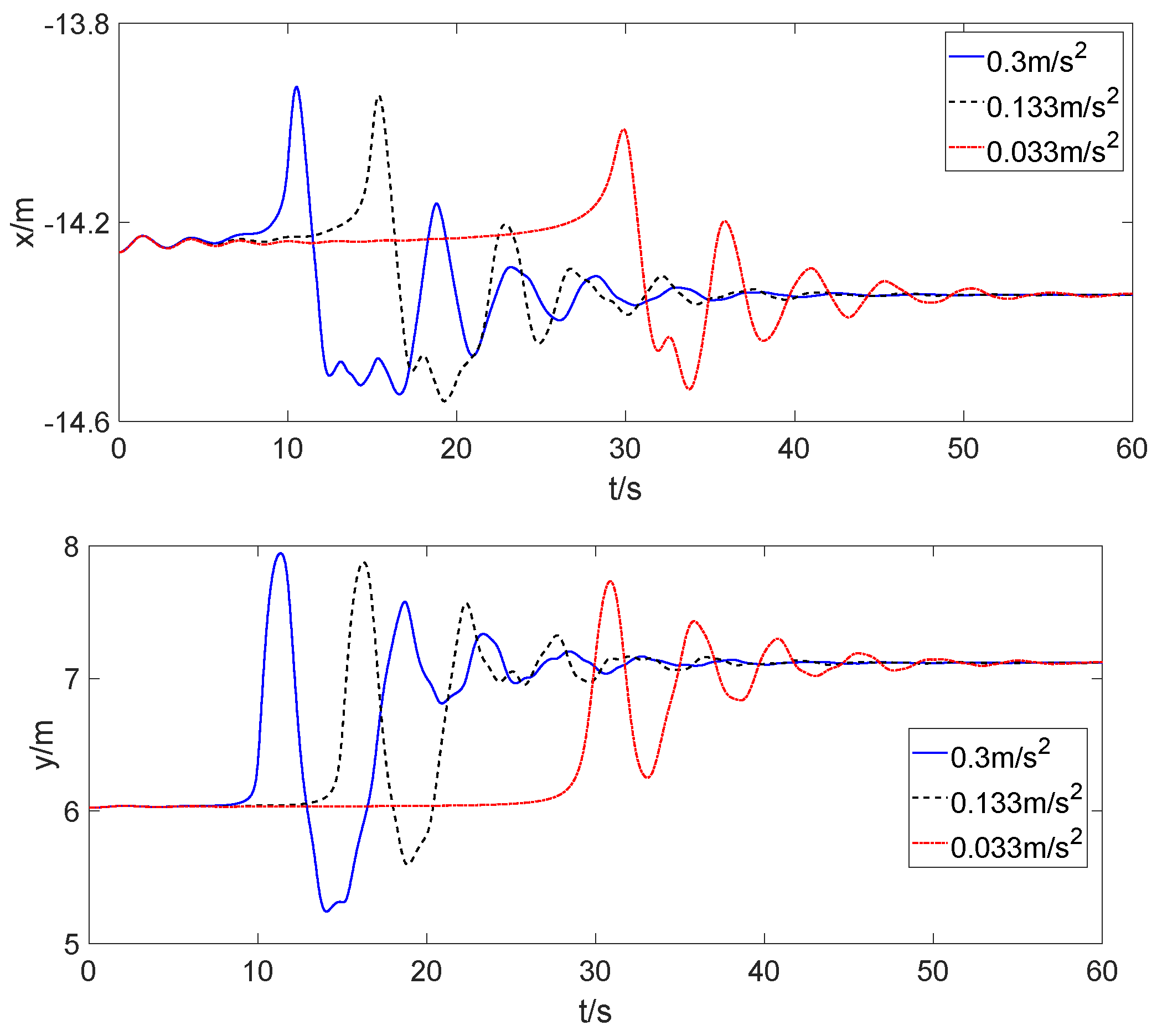
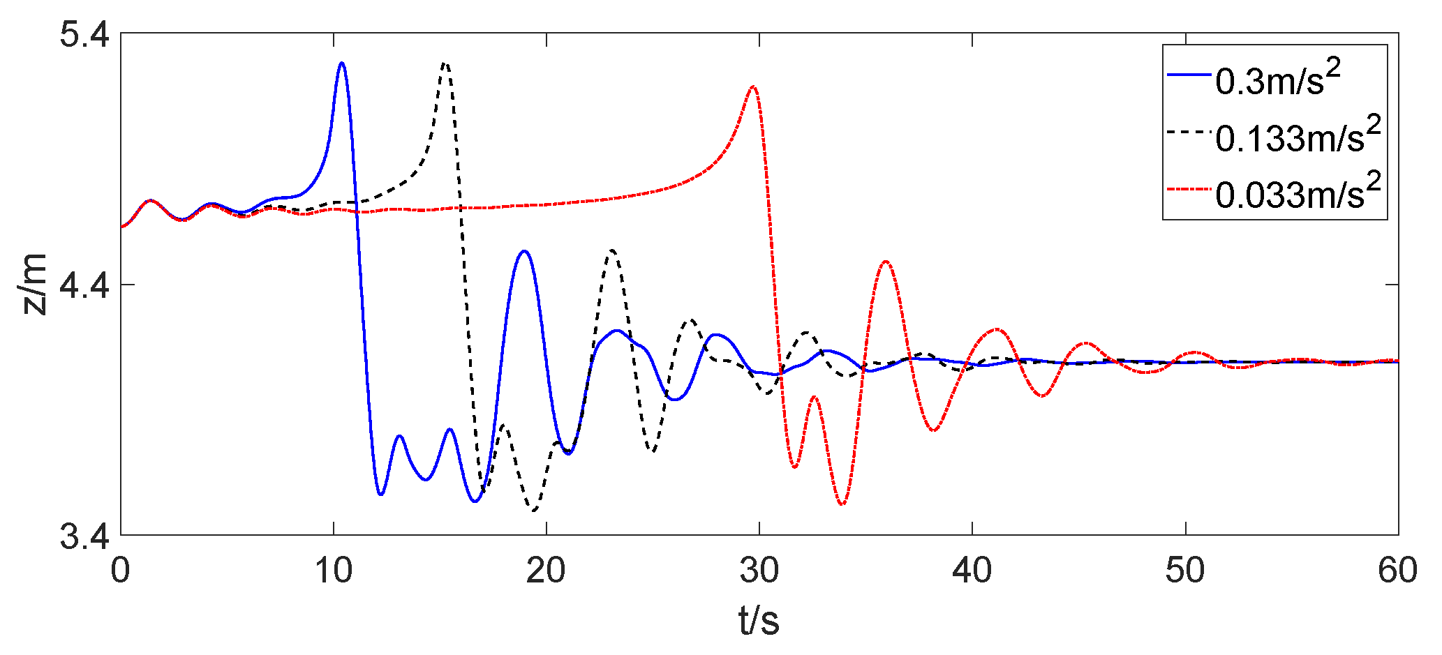
When the receiver aircraft docked with the tanker aircraft at a constant acceleration, the initial position was consistent with Section 3.3. The spatial position changes of the drogue during docking are shown in Figure 7 when the accelerations of the receiver aircraft relative to the tanker aircraft were 0.0333 m/s2, 0.1333 m/s2, and 0.3 m/s2.
Figure 9 shows that when the receiver aircraft docked at a constant acceleration, the position of the drogue continuously sank as the receiver aircraft slowly approached the tanker aircraft. Compared to the constant speed, the position of the drogue changed relatively consistently at different accelerations. When the receiver aircraft approached the initial position of the drogue, the speed and position of the drogue also changed sharply. After a sharp change, the drogue gradually tended to achieve a stable position and finally reached equilibrium.

3.5. Dynamic Analysis after Docking

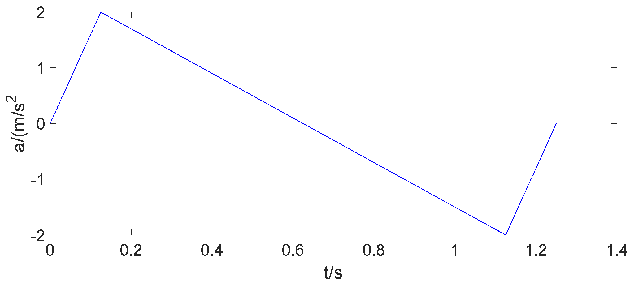
After docking, the receiver aircraft did not immediately remain relatively stationary with the tanker aircraft. A process was required to reach relative stillness. The motion of the receiver aircraft relative to the tanker aircraft after docking is shown in Figure 10.
In this process, we assumed that the last segment of the hose was variable and satisfied Hooke’s law. Considering the characteristic of the hose that were not compressed under force, when the pulling force of the hose was less than zero, it was specified that the pulling force of the hose was zero.
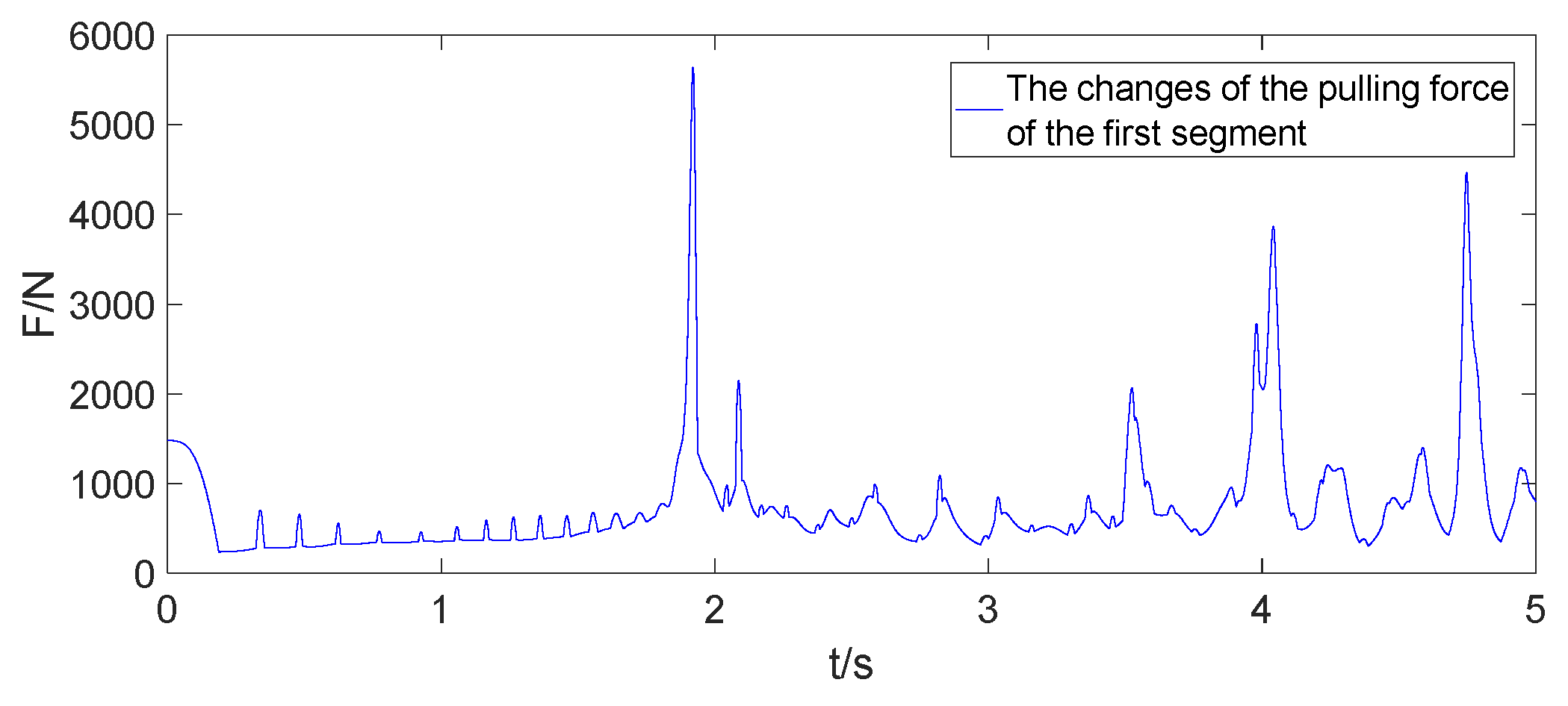
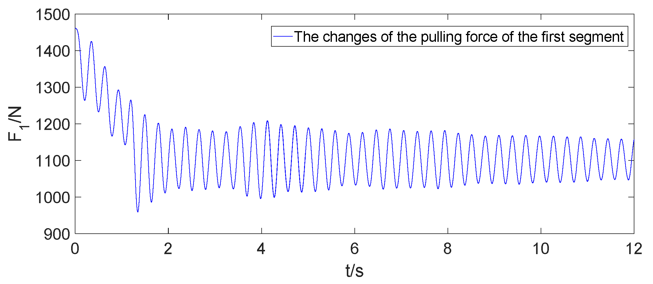
As shown in Figure 11, it can be seen that in the initial stage of docking, the pulling force of the first segment of the hose was relatively small. However, as time went on, there began to be a significant oscillation, and the amplitude increased sharply, with a maximum value of nearly 6000 N, which led to a whiplash phenomenon. It was because gravity pulled down the relaxed hose, which caused an increase in the angle of attack from the front to the middle of the hose. Therefore, the lift of the hose increased and the hose was lifted again. At the same time, under the influence of airflow, this phenomenon gradually developed towards the back end, resulting in more and more severe oscillations, ultimately forming a whiplash effect. Whiplash is a common phenomenon in hose-and-drogue aerial refueling and is difficult to avoid. Therefore, to suppress the development of whiplash as much as possible, a reel is usually added to aerial refueling equipment. After docking, the reel will recycle a part of the hose, reducing the angle of attack of the front and middle parts. This reduction in the angle of attack decreases the amplitude of whiplash, thereby preventing the hose from generating a large pulling force or breaking due to an excessive pulling force.
As shown in Figure 12, a reel is added to the hose-and-drogue system. During docking, the recovered and released hose only affected the length of the first segment and did not affect the other segments; the pulling force on the reel can be defined as follows.
T r t = T 1 0 l 1 t l 1 0 , 0 < l 1 t < l 1 0
where Tr(t) is the pulling force on the reel at t time, T1(0) is the pulling force on the first segment at the initial moment, and l1(t) is the length of the first segment at t time. Its second derivative can be calculated by the following.
l ¨ 1 = T 1 t T r t m r
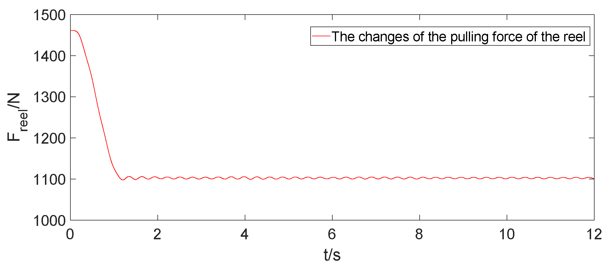
After adding the reel, the system was simulated again. The simulation results are shown in Figure 13. It can be seen that the pulling force of the hose significantly decreased, with a maximum value of less than 1500 N. Due to the reel, the oscillation amplitude of the pulling force was very small, which ensured the safety of the aerial refueling.

4. Conclusions

The motion and dynamic characteristics of the hose-and-drogue system during docking through numerical simulation were investigated in the paper. Firstly, to verify the model’s accuracy, the equilibrium positions of the hose-and-drogue system were simulated when the tanker aircraft was located at different heights and speeds. In addition, the motion of the hose-and-drogue system was studied during docking. The simulation results showed that during docking, the bow wave could damage the equilibrium of the hose-and-drogue system and cause the drogue to deviate from the equilibrium position. Although the speed and acceleration of docking were different, the motion of the hose-and-drogue system had similarities. Finally, a deceleration model of the receiver aircraft was established, and the pulling force of the reel was related to the length of the first segment. The simulation results showed that the reel could significantly reduce the pulling force of the hose during docking, preventing cracks or fractures in the hose.
The model and simulation in this paper can provide some reference for designing aerial refueling control systems during docking. At the same time, this paper also proposes a method for reducing the pulling force during docking, which can ensure the safety of docking.

Author Contributions

The contributions of the authors are the following: Conceptualization, Y.C.; Methodology, H.W.; Validation, L.H.; Investigation, C.Z.; Resources C.Z. and Y.C.; Data Curation C.Z. and L.H.; writing—Original Draft Preparation, C.Z.; writing—Review & Editing, Y.C., H.W. and L.H.; project Administration, Y.C. All authors have read and agreed to the published version of the manuscript.

Funding

This study research received no external funding.

Data Availability Statement

All the data used during the study appear in the submitted article.

Acknowledgments

We offer our thanks to the Smart Aircraft Team of Xi’an Jiaotong University for providing support.

Conflicts of Interest

The authors declare no conflict of interest.

References

  1. Lu, Y.P.; Yang, C.X.; Liu, Y.Y. A survey of modeling and control technologies for aerial refueling system. Acta Aeronaut. Astronaut. Sin. 2014, 35, 2375–2389. [Google Scholar]
  2. Zhong, D.X.; Li, Y.Q.; Li, Y.R. State-of-the-art and Tendency of Autonomous Aerial Refueling Technologies for Unmanned Aerial Vehicles. Aeronaut. Sci. Technol. 2014, 25, 1–6. [Google Scholar]
  3. Lofthouse, A.J.; Nathan, B. CFD modeling of B-52 and KC-135 in air refueling formation. In Proceedings of the 35th AIAA Applied Aerodynamics Conference, Denver, CO, USA, 5–9 June 2017. [Google Scholar]
  4. Chen, L.L.; Liu, X.Q. Numerical Analysis of Refueling Drogue Oscillation During Refueling Docking. Trans. Nanjing Univ. Aeronaut. Astronaut. 2016, 33, 173–179. [Google Scholar]
  5. Li, M.Z.; Wang, Z.; Zhao, Y.T.; Zhang, K.Y.; Shi, Y.Q. Dynamic response analysis of aerial refueling hose-drogue under complex flow field. Flight Dyn. 2020, 38, 32–36. [Google Scholar]
  6. Zhang, X.M.; Shao, Z.; Shi, J.Y. Dynamic modeling and simulation of aerial refueling hose-drogue. Technol. Innov. Appl. 2020, 1, 19–21. [Google Scholar]
  7. Xu, F.R. Calculation of the towing position of aerial refueling hose. Chin. Q. Mech. 1985, 3, 57–63. [Google Scholar]
  8. Ribbens, W.; Saggio, F.; Wierenga, R.; Feldmann, M. Dynamic modeling of an aerial refueling hose & drogue system. In Proceedings of the 25th AIAA Applied Aerodynamics Conference, Miami, FL, USA, 25–28 June 2007. [Google Scholar]
  9. Erickson, A.J.; Richards, P.W.; Chaturvedi, A.N. Aeroelastic Modeling of Hose and Drogue Aerial Refueling Systems Including a Hose Reeling Mechanism. In Proceedings of the AIAA SciTech Forum, San Diego, CA, USA, 7–11 January 2019. [Google Scholar]
  10. Zhu, Z.H.; Meguid, S.A. Elastodynamic analysis of aerial refueling hose using curved beam element. AIAA J. 2006, 44, 1317–1324. [Google Scholar] [CrossRef]
  11. Ro, K.; Kamman, J.W. Modeling and Simulation of Hose-Paradrogue Aerial Refueling Systems. J. Guid. Control Dyn. 2010, 33, 53–63. [Google Scholar] [CrossRef]
  12. Zhang, J.; Yuan, S.Z.; Gong, Q.Q. Modeling and Control of Shaking Motion of Aerial Refueling Hose-Drogue. J. Syst. Simul. 2016, 28, 388–395. [Google Scholar]
  13. Cheng, J.F.; Ji, K. Dynamic modeling and simulation of variable-length hose–drogue aerial refueling systems. AIP Adv. 2022, 12, 015104. [Google Scholar] [CrossRef]
  14. Cheng, J.F.; Deng, F.; Liu, X.Q.; Ji, K. Active Control of Aerial Refueling Hose-Drogue Dynamics with the Improved Reel Take-Up System. Int. J. Aerosp. Eng. 2022, 2022, 4696037. [Google Scholar] [CrossRef]
  15. Cai, Y.P.; Wang, Y.X.; Wang, D.Y.; Ren, B.; Wang, H.L. Study on dynamic characteristics of refueling hose during release. Tactical Missile Technol. 2022, 6, 54–62. [Google Scholar]
  16. Min, Q. Dynamic modeling and load calculation of hose whipping phenomenon of aerial refueling hose-drogue assembly. J. Sichuan Univ. Sci. Eng. (Nat. Sci. Ed.) 2020, 33, 76–82. [Google Scholar]
  17. Wang, H.T.; Dong, X.M.; Dou, H.F. Dynamic modeling and characteristics analysis of hose-paradrogue aerial refueling system. J. Beijing Univ. Aeronaut. Astronaut. 2014, 40, 92–98. [Google Scholar]
  18. Wang, H.T.; Dong, X.M.; Xue, J.P.; Liu, J.L. Dynamic modeling of a hose-drogue aerial refueling system and integral sliding mode backstepping control for the hose whipping phenomenon. Chin. J. Aeronaut. 2014, 27, 930–946. [Google Scholar] [CrossRef]
  19. Wang, H.T.; Dong, X.M. Dynamics and Control of Aerial Refueling, 1st ed.; National Defense Industry Press: Beijing, China, 2016; pp. 202–207. [Google Scholar]
  20. Styuart, A.; Yamashiro, H.; Stirling, R.; Mor, M. Numerical simulation of hose whip phenomenon in aerial refueling. In Proceedings of the AIAA Atmospheric Flight Mechanics Conference, Portland, OR, USA, 8–11 August 2011. [Google Scholar]
  21. Zhang, X.F.; Hu, M.Q.; Tian, P.Y. Analysis of impact on bending moment of the hose in dynamic modeling of aerial refueling hose-drogue system. Flight Dyn. 2018, 36, 92–96. [Google Scholar]
  22. Wang, W.; Liu, X.Z.; Wang, P. Dynamics of hose-drogue refueling systems during coupling. Flight Dyn. 2013, 31, 180–183. [Google Scholar]
  23. Bhandari, U.; Thomas, P.R.; Bullock, S.; Richardson, T.S. Bow Wave Effect in Probe and Drogue Aerial Refueling. In Proceedings of the AIAA Guidance, Navigation, and Control Conference, Boston, MA, USA, 19–22 August 2013. [Google Scholar]
  24. Zhou, R.X.; Yang, S.J.; Lin, Y.J. Design and research of the hose-drogue aerial refueling hardware-in-the-loop simulation system. J. Graph. 2021, 42, 478–484. [Google Scholar]
  25. Zhang, X.F.; Hu, M.Q.; Zhang, D.; Tian, P.Y.; Wang, N. Influence of the receiver aircraft’s bow wave on the motion characteristics of the drogue in hose-drogue refueling system. In Journal of Physics: Conference Series, Proceedings of the 2st International Conference on Fluid Mechanics and Industrial Applications, Guilin, China, 12–14 July 2018; IOP Publishing: Bristol, UK, 2018. [Google Scholar]
  26. Dai, X.H.; Wei, Z.B.; Quan, Q. Modeling and simulation of bow wave effect in probe and drogue aerial refueling. Chin. J. Aeronaut. 2016, 29, 448–461. [Google Scholar] [CrossRef]
  27. Wang, J.; Dong, X.M.; Xu, Y.J.; Wang, H.T.; Liu, J.L.; Shi, C. Simulation and analysis of the bow wave effect of the receiver in hose-drogue aerial refueling. Flight Dyn. 2016, 34, 54–58. [Google Scholar]
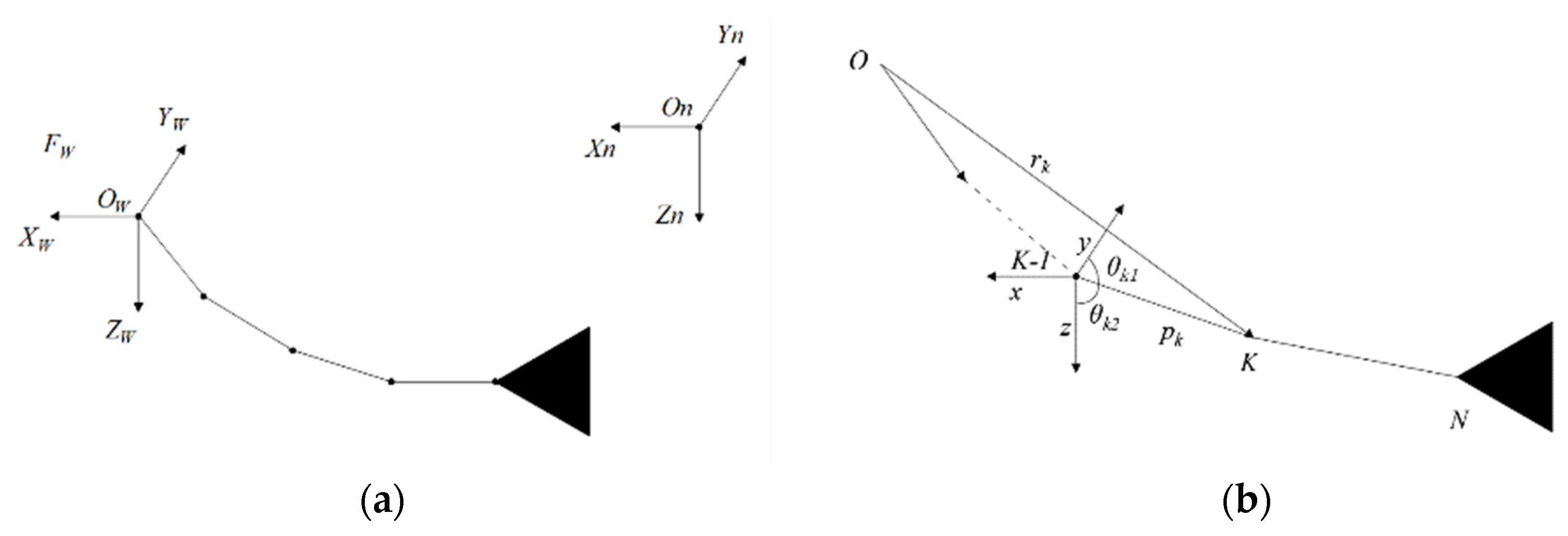
Figure 1. (a) Schematic diagram of the hose-and-drogue system; (b) model of the hose-and-drogue system.
Aerospace 11 00013 g001
Figure 2. The relative position of point B and the point source.
Aerospace 11 00013 g002
Figure 3. The Rankine body flow model.
Aerospace 11 00013 g003
Figure 4. The simulation process of the complete model.
Aerospace 11 00013 g004
Figure 5. The equilibrium positions of the hose-and-drogue system at different heights with a speed of 100 m/s.
Aerospace 11 00013 g005
Figure 6. The equilibrium positions of the hose-and-drogue system at different speeds with a height of 5 km.
Aerospace 11 00013 g006
Figure 7. The equilibrium positions of the drogue in the direction of X, Y, and Z at different positions of the receiver aircraft.
Aerospace 11 00013 g007
Figure 8. Motion of the drogue in the direction of X, Y, and Z at different docking speeds.
Aerospace 11 00013 g008aAerospace 11 00013 g008b
Figure 9. Motion of the drogue in the direction of X, Y, and Z at different docking accelerations.
Aerospace 11 00013 g009aAerospace 11 00013 g009b
Figure 10. The motion model of the receiver aircraft after docking.
Aerospace 11 00013 g010
Figure 11. The change in the pulling force of the first segment without a reel.
Aerospace 11 00013 g011
Figure 12. Schematic diagram of the hose-and-drogue system with the reel.
Aerospace 11 00013 g012
Figure 13. The change in the pulling force of the first segment and with a reel.
Aerospace 11 00013 g013aAerospace 11 00013 g013b
Table 1. The hose-and-drogue system’s characteristics.
Parameter/UnitSymbolValue
Hose length/mL15
Mass per unit length hose/(kg/m)μ4
Hose outer diameter/mdo0.066
Hose inner diameter/mdi0.051
Drogue mass/kgmdrogue30
Drogue diameter/mddrogue0.61
Hose elastic modulus/MPaE13.78
Hose polar moment of inertia/m4I5.993 × 10−7
Drogue drag coefficientcdrogue0.8
Disclaimer/Publisher’s Note: The statements, opinions and data contained in all publications are solely those of the individual author(s) and contributor(s) and not of MDPI and/or the editor(s). MDPI and/or the editor(s) disclaim responsibility for any injury to people or property resulting from any ideas, methods, instructions or products referred to in the content.