Article

Toward Zero Carbon Emissions: Investigating the Combustion Performance of Shaped Microcombustors Using H2/Air and NH3/Air Mixtures

Department Engineering for Innovation, University of Salento, Via per Monteroni, 73100 Lecce, Italy
*
Author to whom correspondence should be addressed.
Aerospace 2024, 11(1), 12; https://doi.org/10.3390/aerospace11010012
Submission received: 1 December 2023 / Revised: 12 December 2023 / Accepted: 14 December 2023 / Published: 22 December 2023

Abstract

:
The research effort in the microcombustor field has recently increased due to the demand for high-performance systems in microelectromechanical and micro power generation devices. To address rising concerns about pollutants from fossil sources, zero-carbon fuels such as hydrogen (H2) and ammonia (NH3) have been considered as an alternative in microcombustion processes. In a microcombustor, the surface area-to-volume ratio is much higher compared to conventional combustion systems, resulting in faster heat transfer rates and more intense combustion reactions. However, achieving efficient mixing of fuel and an oxidizer in a microcombustor can be challenging due to its small size, particularly for highly reactive fuels like H2. For NH3, challenges in microcombustion involve a low reactive, high ignition temperature (923 K vs. 793 K of H2) and high concentration of NOx combustion products. Therefore, studying the performance of these fuels in microcombustors is important for developing clean energy technologies. In this paper, to explore features of non-premixed NH3/air and H2/air combustion in micro-scale combustors, an Ansys Fluent numerical investigation was conducted on a Y-shaped microcombustor. Results show that for combustion with H2, stationary flames can be achieved even at lower equivalence ratios. Additionally, the pollutants generated from H2 in the flame are generally twice those of NH3. The overall efficiency of the microcombustor is two times greater for NH3 conditions than for H2 conditions.

1. Introduction

1.1. Background

The 17 Sustainable Development Goals (SDGs) outlined for 2030 emphasize the importance of improving the performances of microthermal energy conversion devices [1]. Combustion-based microdevices have revolutionized the field of energy conversion in the past 30 years due to their high energy density, low weight, compact size, and long lifespan [2,3,4,5,6,7,8,9]. These devices not only offer energy benefits but also have significant economic and social implications. Microcombustors are essential components in compact energy systems, such as micro-thermophotovoltaic [9,10,11] and micro-thermoelectric systems [12,13]. In these applications, the main challenge is to achieve the highest possible temperature difference between the inlet and outlet to reach wall temperatures between 1300 and 1800 K [14]. The microscale power generation length scale is typically defined as being below 1 mm [15]. The microcombustion technology revolution has led to systems that are lighter and smaller and have higher energy density [1,16]. It has been widely adopted in various engineering power systems such as micro rotor engines and turbines [17,18]. The high area-to-volume ratio and short mixture residence time make maintaining a stable flame in micro burner systems a challenging task [19,20,21,22].
The study of flame stability is crucial in numerous fields including energy production, propulsion systems, and safety engineering. The stability of flames is influenced by various factors including heat and flow recirculation, which have been shown by multiple researchers to have a significant impact. Addressing flame stability challenges requires innovative approaches, including exploring new mixing configurations and implementing advanced thermal management strategies [23,24].
Conducting experimental microcombustion research is complex, time-consuming, and expensive, which is why significant computational effort is invested in numerical modeling to reduce the need for experimental validation and final design phases [25]. Micro-Electro-Mechanic Systems (MEMSs) are a promising alternative to a combustion device, but their effectiveness is hindered by various challenges such as batteries’ short life, recharging time, and energy density [26]. Currently, the best battery performances achieve 0.5 kJ/g [27], which is 300 times less than hydrogen and leads to reduced resources and cost [28]. Short battery life and long recharging times are other persistent issues with conventional batteries.

1.2. Literature Review

The impact of geometry on microcombustion applications is a highly relevant topic today, as evidenced by numerous studies [29]. Variations in geometry can greatly influence thermophysical properties such as heat conduction and residence time in the combustion chamber, affecting the device performances. For instance, Peng et al. [30] conducted numerical simulations to explore the effects of reducing wall thickness in hydrogen–air combustion to improve the flame area and wall temperature. They simulated a premixed H2-air combustion in the microcombustors with different backward-facing steps and wall thicknesses.
Another crucial aspect that has recently been investigated is the impact of increased thermal conductivity on the combustion area, as discussed in [31]. The researchers studied three catalytic microcombustors made of various materials. They compared their experimental results with those obtained from CFD simulations and observed that the performance of each material varied.
Improved flame stability can be achieved through better control of thermal energy loss, resulting in a higher inlet mass flow rate, increased maximum temperature, and improved combustion performance. Effective flame recirculation and thermal management in microcombustors can also enhance residence time and stabilize the flame [32,33]. Recently, Resende et al. [34] analyzed the flame dynamics of a H2/air mixture in a wavy micro-channel. Their results showed that at low inlet velocity (4 m/s), the flame became stable, and, at higher inlet velocities, the flame showed pulsatory burst dynamics.
Despite hydrogen’s advantages, there are still challenges associated with its storage, distribution, and infrastructure. NH3 potential as an alternative fuel stems from its H2-rich composition and the absence of carbon, which makes it an attractive option in the pursuit of reducing greenhouse gas emissions (GHGs) [35,36,37]. Microcombustion has serious heat loss due to the large ratio of surface area to volume. This leads to some unwanted characteristics such as a narrow blow-out limit. NH3 has relatively low flame propagation speed and chemical activity compared to other hydrocarbon fuels. Therefore, the combustion condition for NH3 is demanding especially in a microcombustor. This work compares the flame behavior of a H2-air and NH3/air mixture for combustion in a Y-shaped microcombustor.
The effects of using the mixture of NH3/air are discussed in terms of emissions and combustion efficiency compared to the H2 condition.
Within the present work, authors start from their previous studies [38] to develop a numerical model is developed in a Chemkin environment to study the combustion evolution for the mixture in a non-premixed microcombustor. The Chemkin model is used to validate the laminar burning velocity (LBV). Secondly, the developed scheme of chemical equations developed in Chemkin that considers all the species provided from the combustion process is exported to steady-state CFD simulations that use a continuum Navier–Stokes approach. The validity of the model is confirmed by comparing simulation results with experimental data in the case of H2. The simulations are performed using Ansys Fluent 2023 [39].
There are only a few studies on microcombustion fueled with NH3 and several studies using methane (CH4) or H2, also in a blend, as fuel. Due to the diverse conversion pathways of NH3 combustion, different oxides will be generated depending on the fuel. This leads to changes in energy conversion efficiency. The main goal of the study proposed here is to underline the effects of different zero-carbon fuels in a microcombustor on the improvement in thermal performances and on environmental impact of these kinds of fuels.
Utilizing a numerical CFD approach, the paper carries out a step beyond the present knowledge of the thermo-chemical processes distinguishing a microcombustor based on new technology, as it investigates fundamental features that are strongly related to the inefficiency of the heat thermal exchange in the energy conversion process.

2. Materials and Method

2.1. Geometric Features of the Microcombustor

The present study investigates a specific model geometry, featuring a Y-shaped combustion chamber of 200 mm in length with a 90-degree angle and two inlet channels for the considered fuel (hydrogen and ammonia) and dry air, as previously described by Xiang et al., 2020 [40], Xang et al., 2021 [41]. The combustion chamber walls are made of 1-mm-thick quartz glass, and the pressure and temperature are set to 1 atm and 300 K, respectively.

2.2. Modelling Combustion and Kinetic Mechanism Details

The CFD software Fluent 2023 [39] is employed to address the core equations representing conservation of mass, momentum, energy, and chemical species within the fluid, leveraging a second-order upwind scheme. This methodology is reputed for its enhanced accuracy and stability when simulating fluid flows exhibiting strong gradients and discontinuities. A coupled algorithm, recognized as a pressure–velocity coupling technique, is utilized in the simulation. This technique embodies a linkage between velocity and pressure corrections to uphold mass conservation and deduce the pressure field, accompanied by a second-order pressure spatial discretization. Gradients are ascertained utilizing the least squares cell-based scheme. Convergence in the simulation is inferred when the residuals for all parameters fall below 10−4 and the average temperature and the mass fractions of main combustion products are constant. A three-dimensional (3D) steady model is adopted, and the impact of gravity is disregarded. The fundamental governing equations for heat and mass transfer are presented. A segregated solution solver coupled with a sub-relaxation method is employed.
ρ t + ( ρ u i ) x i = 0
( ρ u j ) t + ( ρ u i u j τ i j ) x i = p x j
( ρ h ) t + ( ρ u i h ) x i = ( λ T f ) t j ( h j J j ) x i + j h j R j
( ρ Y i ) t + ρ u i Y i x i = J i x i R i
where ρ is the gas density, p is the pressure, u is the velocity, τ i j is the stress tensor, h is total enthalpy, Ji is the diffusion flux of species i, Yi is the mass fraction of species, T is the temperature, Rj is the net rate of production of species j through chemical reaction i, λ is the thermal conductivity. The effects of convection and radiation (P1 model) on the heat losses are computed considering Equation (5). An ideal gas flow model is adopted with a mixing law, cp.
Q ˙ l o s s = h 0 A T w T 0 + ε σ A ( T w 4 T 0 4 )
A numerical model is proposed in this study to analyze combustion chemical effects. The combustion mechanism proposed by Mei et al. [42] was modified and validated. This mechanism incorporates the base H2 mechanism from Hashemi et al. [43] and the NH3 sub-mechanism from Shrestha et al. [44] and includes reactions of excited species, such as O2(a1Δg) and O(1D), introduced by Konnov [45].

2.3. Validation of Laminar Burning Velocity Using CHEMKIN

To investigate the flame speed of NH3/air and H2/air mixtures, numerical simulations with different mechanisms were performed using CHEMKIN [46]. A premixed laminar flame speed reactor (PLFSR) calculation module was used in this work to predict laminar burning velocities (LBVs). All the simulations were converged to a grid-independent solution.
The experimental results reported by Mei et al. [42], Ronney [47], and Lhuillier et al. [48], as well as the simulation results reported by Han et al. [49], San Diego et al. [50], Mathieu and Petersen [51], and Li et al. [52], were utilized to validate the updated version of the NH3/air combustion mechanism by correlating the LBVs of NH3/air flame at various equivalence ratios as shown in Figure 1. This figure illustrates that, under lean, stoichiometric, and slightly rich (<1.2) conditions, the current mechanism demonstrated good agreement with the experimental results of Mei [42] and Ronney [47]. However, there are slight deviations on the rich side because of the low LBV values of NH3/air mixtures.
The validation of the H2/air combustion mechanism was achieved by establishing a correlation between the LBV experimental data reported by Burke et al. [53], Pareja et al. [54], and Taylor [55] as well as simulation results reported by Alekseev et al. [56] and Konnov et al. [45] at a temperature of 298 K and a pressure of 1 atm across a range of different equivalence ratios, as depicted in Figure 2. In this case, the predicted values using the chosen mechanism are in good agreement with experimental data as well.
The findings of these studies demonstrate that the ammonia/air mixture’s LBV peaks at Φ = 1.1–1.15, whereas the hydrogen/air mixture’s LBV peak value is approximately Φ = 1.50–1.70, 40 times greater than the ammonia/air mixture.

2.4. Computational Domain and Boundary Conditions

Two separate channels are used for the fueling of fuel and air. One channel is for pure H2 or NH3 and the other channel is for air. Both channels represent the inlet conditions with constant flow rates and an inlet temperature of 300 K. A pressure–outlet boundary condition of 1 atm is set at the outlet. The wall is modeled as a no-slip wall with heat transfer to the surroundings accounted for by adopting mixed thermal conditions that include a heat transfer coefficient of 20 W/m2K. The specific quartz glass specific heat capacity and thermal conductivity are 750 J/kgK and 2 W/mK [57]. A direct comparison between H2 and NH3 as fuels was conducted, setting a mixture velocity of 6 m/s for H2 and different Φ from lean blow-out to 1. For NH3, mass flow rates were computed based on a different Lower Heating Value (LHV), ensuring an equivalent heat of the reaction source for each fuel type at the same Φ. Table 1 and Table 2 report the inlet velocity value for every considered case.
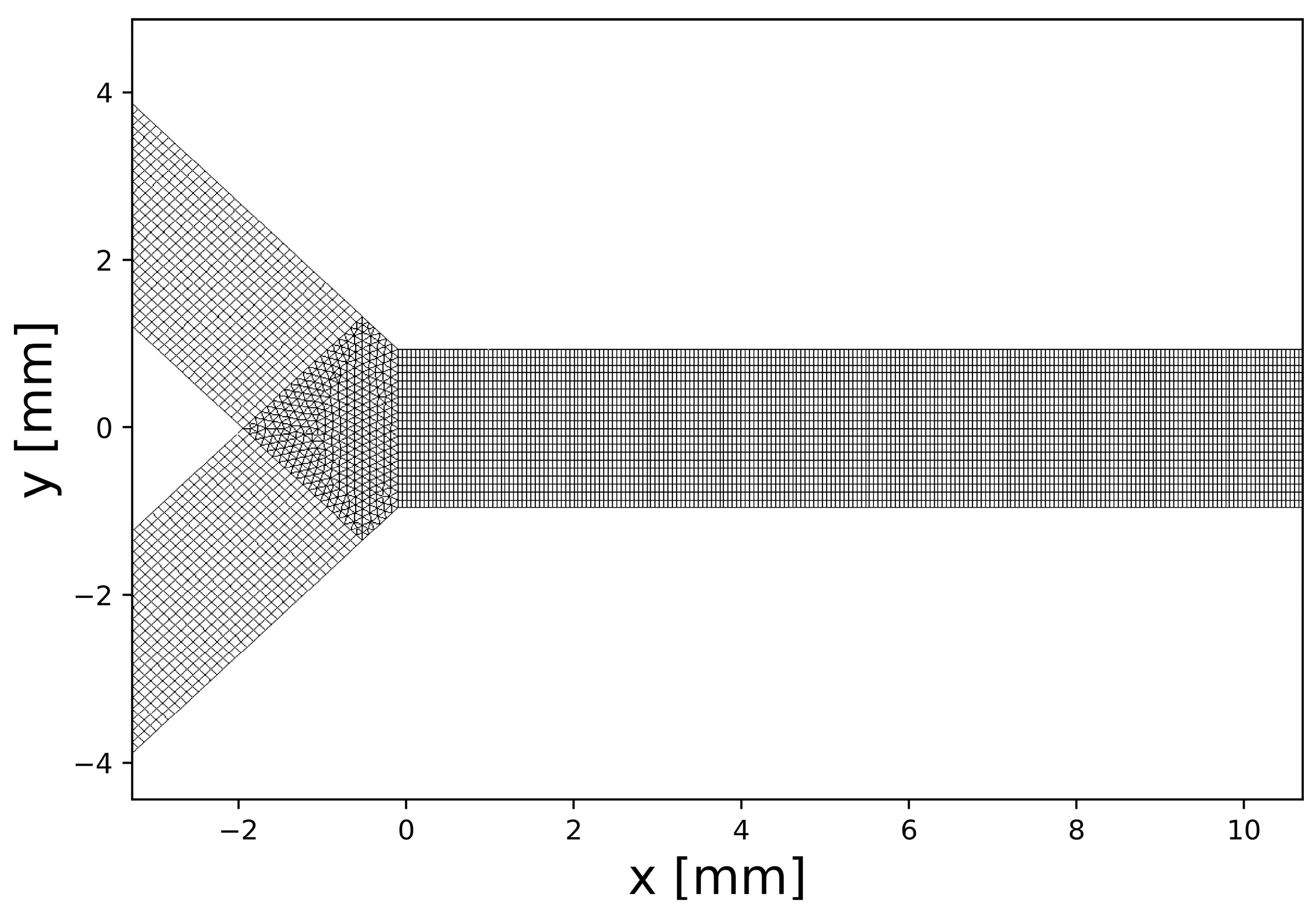
Mesh is realized using hexahedral cells, except for the confluence zone, where prismatic cells are used (Figure 3).
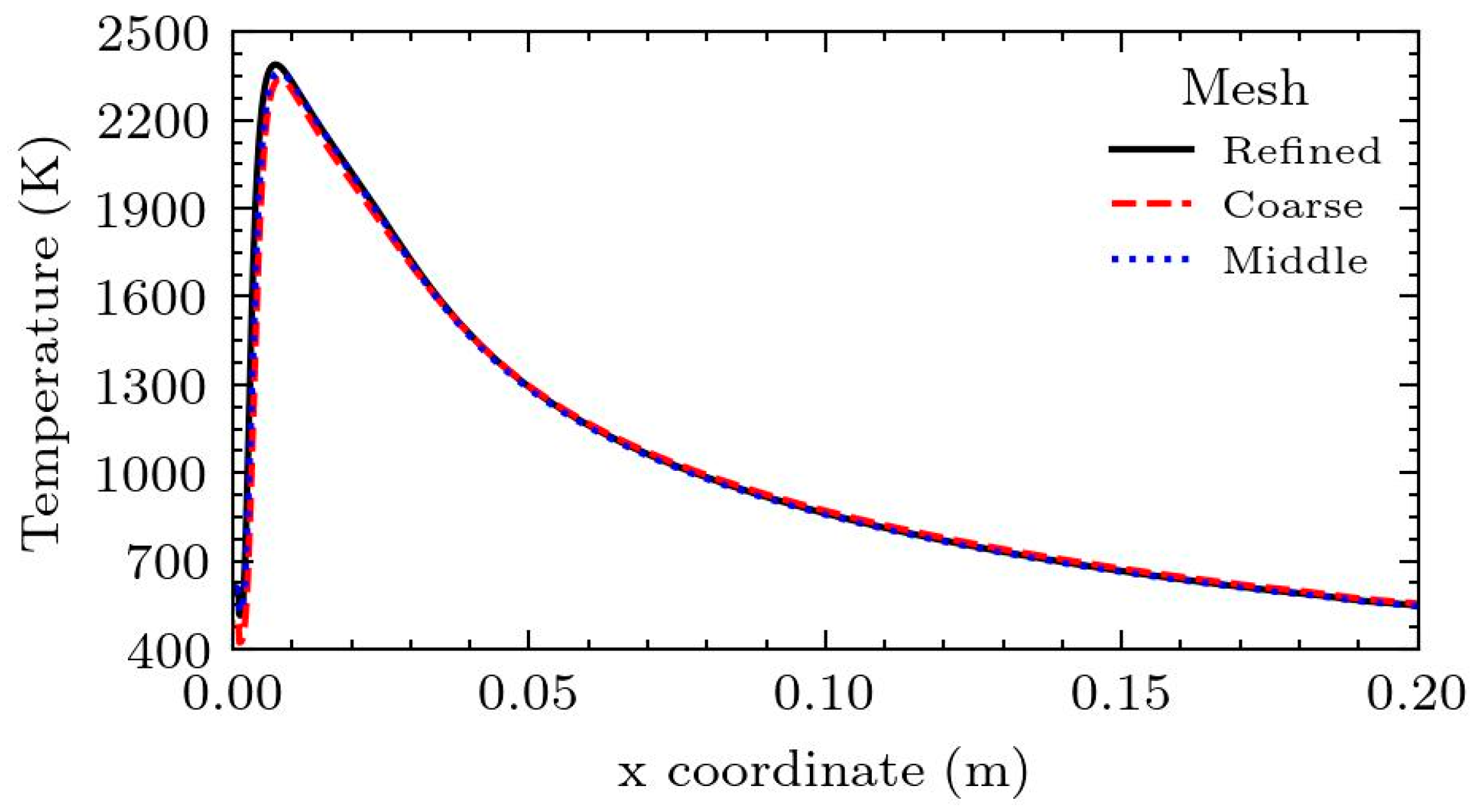
To ensure the grid independence, the simulation results were compared at v = 6 m/s, the H2 case condition with three different grids. To reduce computational times without having any substantial effect on results, the inlet length has been reduced by 100 mm. Three different mesh resolutions, 140,000, 175,000, and 237,000 cells, were compared. The Grid Convergence Index (GCI) for three meshes has been computed [58]. This process allowed us to ascertain the discretization error associated with the numerical solution, improving the overall accuracy and reliability of the models. Refinement was applied in the mixing chamber with r = 1.5. It is known that the relative error for a function f is equal to
ε = | f 2 f 1   f 2 |
P = ln ( f 3 f 2 f 2 f 1 ) / ln ( r )
G C I =   f s   ε r P 1
f * =   r P f 3   f 2   r P 1
The safety factor was equal to 1.25. Temperature values are displayed in Table 3 at x = 9 mm, y = 0, and z = 0.785 for H2-air combustion, velocity being equal to 6 m/s and Φ equal to 1.
GCI for 1/2 mesh was 0.2% while for 2/3 mesh, it was 0.5%. Moreover, the extrapolated f* value was computed with Equation (9) and the predicted value is equal to 2362 K. Thus, the middle mesh has only a 0.5% error, inside the 5% confidence. Figure 4 presents the temperature profiles along the centerline, emphasizing the consistency of our results across different mesh sizes and underscoring the accuracy of our grid independence verification.

2.5. Validation of 3D Model

The simulation results were compared to experimental data for an unburned mixture velocity of 6 m/s and various values for Φ ranging from 0.5 to 1. However, for Φ values lower than 0.6, the simulations did not exhibit a stable flame, and this lack of stability is consistent with the findings in the experimental data. There is no specific numerical parameter available to directly define the chemical flame length and facilitate a direct comparison with the experimental visible flame length. However, correlations between the flame and the mole fraction of OH distribution have been established. Nevertheless, in this study, a promising correlation is observed between the distribution of the heat of reactions and the flame length. By using a threshold of 1 W/m3, meaningful insights can be gained from the relationship between the heat of reactions and flame length. This correlation proves to be valuable in understanding the combustion process within the microcombustor. Figure 5 shows the trend of the heat of the reaction correlated with the flame length identified from the experimental data [41]. Despite some discrepancies, such as the data point at 0.9, the overall trend of the function can be considered in good agreement with the experimental data for the simulation.

3. Results

Considering that variations in Φ can lead to changes in inlet velocity, it is expected that these changes will significantly impact the circulation flow field and subsequently reduce temperature, ultimately affecting the formation of NO. Therefore, we assessed the impact of several critical parameters on NO formation by varying the fuel-oxidizer Φ within a range of 0.5 to 1.0 with an equivalent provided power volumetric flow rate. A direct comparison between H2 and NH3 as fuels was conducted following the boundary conditions displayed in Table 1 and Table 2. As anticipated, experimental results indicate that for H2 fuel, a flame is present when the Φ is greater than 0.5. On the other hand, for NH3 fuel, the minimum Φ required for flame ignition is 0.7. The curves for ammonia are shifted downstream in comparison to those for hydrogen (see Figure 6).
This is due to the lower laminar burning velocity of ammonia in comparison to H2 and HC fuels, which makes it more difficult to sustain. This is due to the lower laminar burning velocity of ammonia in comparison to hydrogen and hydrocarbon fuels, which makes it more difficult to sustain a flame at lower equivalence ratios. Due to different Reynolds and fuel chemistry, ammonia flames move toward the outlet, becoming a flame at lower equivalence ratios. Due to different Reynolds and fuel chemistry, ammonia flames move toward the outlet. Figure 7 shows temperature centerlines for different equivalence ratio values at the same source of power of 26 W and 19.9. At Φ = 1, the maximum temperature of ammonia/air flames is about 200 K lower than that of H2/air flames at the same Φ. The flame temperature is mostly affected by the specific heat of combustion and the flame speed. As the flame temperature and specific heat of combustion are quite higher for H2, the flame temperature is higher. The variation in the Φ demonstrates distinct behaviors between H2 and NH3 in combustion scenarios. As the Φ varies, the peak temperature of H2 exhibits a significant increase, while the peak temperature of NH3 remains relatively stable. The effect of Φ on NH3 is more pronounced in the extension of the flame region at temperatures exceeding 1800 K, as evident from Figure 7.
In the simulations of NH3 combustion conducted, it was observed that higher equivalence ratios resulted in lower levels of nitrogen oxides (NOx) (Figure 8).
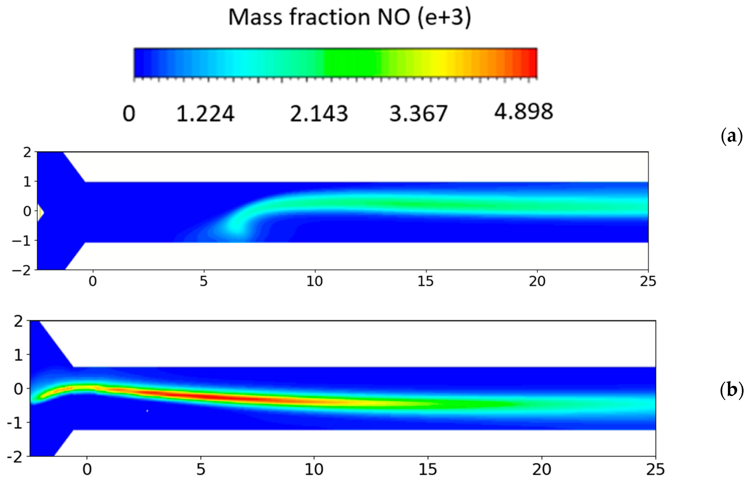
This can be attributed to several factors inherent in the combustion dynamics of NH3. Enhanced combustion efficiency in ammonia combustion processes at elevated equivalence ratios plays a pivotal role in mitigating NOx emissions. This is primarily because higher equivalence ratios facilitate a more complete combustion of the fuel, predominantly yielding water and nitrogen. Consequently, this reduces the incidence of partial combustion, a process that typically leads to the formation of NOx. Therefore, the modulation of equivalence ratios in ammonia combustion emerges as a critical parameter in curtailing the generation of nitrogen oxides, aligning with environmental directives and sustainability goals. On the other hand, one important NO production route from the combustion of nitrogen-free fuels in air, such as hydrogen, is the thermal-NO mechanism, usually referred to as the extended Zel’dovich mechanism [59], which is favored at high temperatures. So, the mole fraction of the NO value is two times that of the ammonia/air combustion (Figure 8b). The symmetry plane contours of the different species produced at ϕ = 0.9 are presented for the symmetry plane predicted in the case of the NH3/air mixture. In Figure 9, the temperature symmetry plane field is provided.
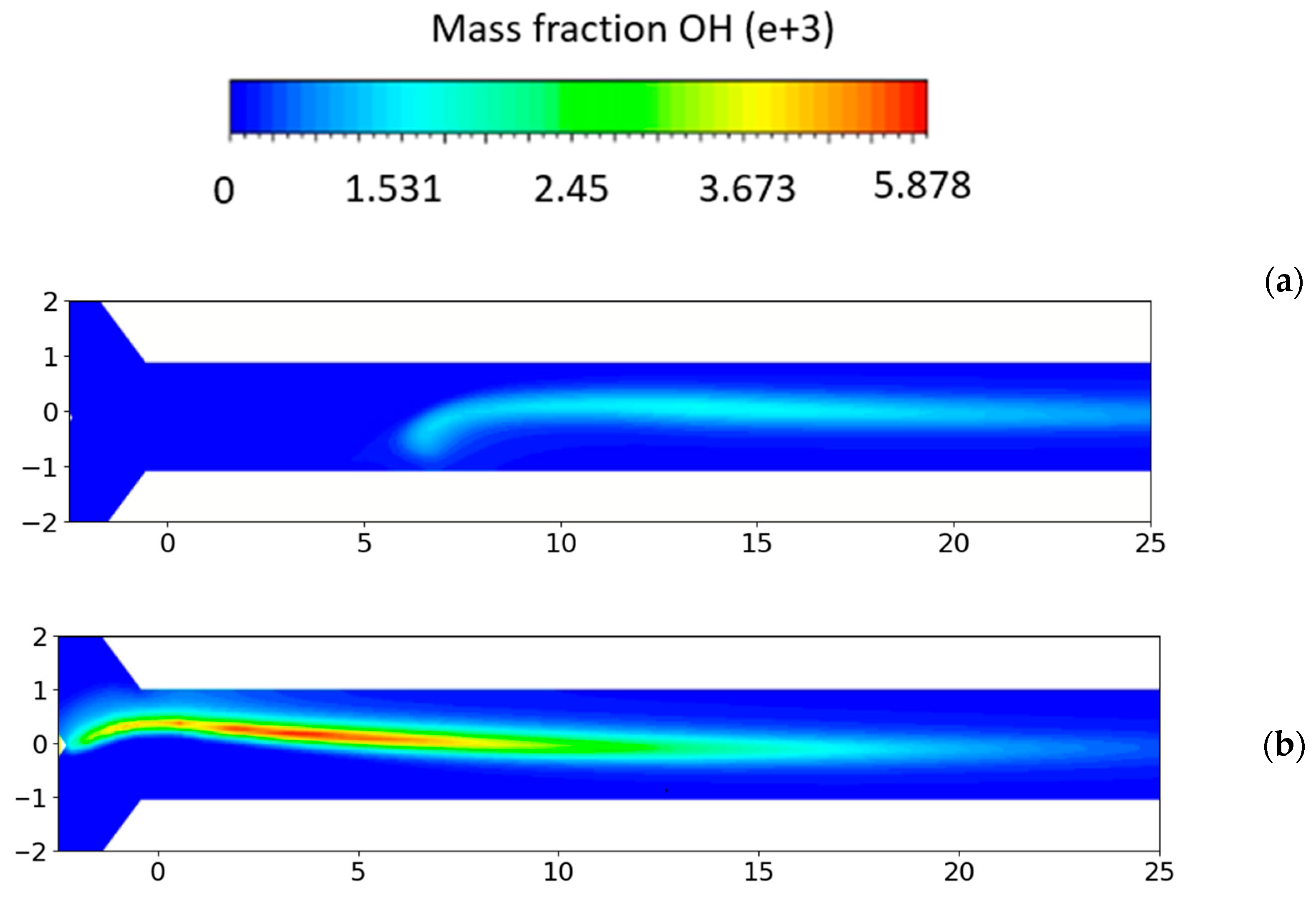
NH3 burning decreases both flame temperature (Figure 9a,b) and the concentration of the light radicals, as OH, relative to H2, (Figure 10a,b) which negatively impacts the NH3 flame reactivity, and thus flame burning velocity. Hence, the NH3 flame is shifted forward compared to that of H2. This information is reflected in both the NO concentration and the concentration of water vapor produced through combustion in both cases (see Figure 11a,b). A high concentration of NO is found to be associated with excess oxygen (O2) atoms and OH radicals. This is the reason why NO concentrations are lower for NH3 at higher equivalence ratios. OH primarily reacts with NH3 through H abstraction. Other secondary consumption steps include reactions with H and O, with NH2 being the common product. Oxidation of NHi (i = 0, 1, 2) may primarily lead to NO formation through an HNO intermediate or to NO reduction through NHi + NO reactions, depending on the concentration of O/H radicals. The abundance of O/H radicals leads to the conversion of NHi + O and may inhibit the reduction of NO by NHi radicals. Furthermore, the HNO intermediate channel is also a main NO production path in NH3/air flames. HNO is mainly due to the reaction of NH2 with O atoms. HNO is converted to NO mostly reacting with H, OH, and O2, and through thermal dissociation.

Microcombustor Efficiency Evaluation

The efficiency of the system is calculated as the ratio of the enthalpy increase between the inlet and outlet to the total input thermal power, which encompasses the output chemical power from the complete combustion of fuel considered (see Equation (4)). Equation (11) is used to calculate the fuel conversion efficiency, denoted as η f , which serves as an indicator of whether complete combustion has been achieved in the chamber wall.
η c = m ˙ e x i t   c p   T e x i t m ˙ i n l e t   c p   T i n l e t m ˙ f   L H V f
η f = 1   m ˙ f   o u t l e t   m ˙ f   i n l e t
Table 4 illustrates the combustion efficiency, revealing that the overall efficiency of the microcombustor is higher under NH3 fueling conditions compared to hydrogen conditions. In all the configurations examined, whether using NH3 or H2 as fuels, we consistently observe nearly complete combustion. This is evident in the fuel conversion efficiency consistently exceeding 99%. A crucial factor contributing to this high efficiency is the system’s geometry.
This design promotes more effective mixing of the fuel with the oxidizer and ensures an ample residence time for the combustion process to reach completion.
NH3 has a lower LHV, specifically 18.6 MJ for NH3 compared to 190 MJ for H2. So, the combustion efficiency is greater mainly because of the forward shift of the flame, which results in lower heat losses.
It is important to emphasize that in this study, the comparison was made at equal equivalence ratios and supplied power, but the mixture mass flow rates are different and significantly higher for NH3, thus making the efficiency comparison useful but in need of a further in-depth analysis.
Higher equivalence ratios correspond to lower efficiencies due to significant chamber wall losses: in fact, even though the thermal power input increases, the wall losses grow more significantly, resulting in a decrease in combustion efficiency. Equation (5) results, as presented in Table 4, depict the heat losses through the walls for each case. The notably higher diffusivity of H2 significantly amplifies the mixture’s thermal diffusivity, leading to a more rapid spread of heat and enhanced heat transfer to the combustion chamber walls. This phenomenon is clearly illustrated in Figure 7, where the temperature of H2 decreases.
Additionally, an essential factor influencing the heat transfer process is the role of radiation. In the combustion of hydrogen, a larger amount of water vapor is produced compared to NH3 combustion. This increase in water vapor results in heightened radiation, contributing to the observed greater wall losses in H2 combustion.

4. Conclusions

A Y-shaped microcombustor designed for eco-friendly fuels is analyzed in this research.
Due to their distinct attributes, microcombustors exhibit different combustion dynamics for H2 and NH3 when compared to larger-scale combustion apparatuses.
Numerical simulations developed in an Ansys Fluent environment investigate the NOx emission behaviors considering the impact of the flow field.
A 3D CFD computational framework incorporating intricate chemical–kinetic mechanisms is crafted and authenticated through juxtaposition with existing experimental findings from the literature.
The outcomes demonstrate the influence of the different fuels on the generated species, emissions, and the microcombustor efficiency.
Thermal performance alongside NOx generation processes is assessed under scenarios of NH2/air and H2/air mixtures, with a steady flow velocity of 6 m/s and varying equivalence ratios. The NOx formation in the microcombustor follows the mechanism of NOx following the temperature distribution in agreement with the Zeldovich theory.
Specifically, with H2 combustion, stable flames are attainable even at reduced equivalence ratios, leading to elevated flame temperatures and pollutant emissions.
The microcombustor-predicted efficiencies and heat losses through the walls are evaluated and discussed.
This research could represent an important tool in the microcombustor field, and thus in MEMS devices, which are a current research topic deeply investigated in these past few years.

Author Contributions

Conceptualization, G.M. and M.G.D.G.; methodology, G.M. and M.G.D.G.; software, G.C. and Z.A.S.; validation, G.C. and Z.A.S.; formal analysis, G.C. and G.M.; investigation, G.M., G.C. and Z.A.S.; resources, M.G.D.G.; data curation, G.M. and Z.A.S.; writing—original draft preparation, G.C., G.M. and Z.A.S.; writing—review and editing, G.M. and G.C.; visualization, G.C. and M.G.D.G.; supervision, G.M. and M.G.D.G.; project administration, M.G.D.G.; funding acquisition, M.G.D.G. All authors have read and agreed to the published version of the manuscript.

Funding

The work was supported and funded by Project MOST Research Project: Sustainable Mobility Center (Centro Nazionale per la Mobilità Sostenibile —CNMS) CUP progetto: F83C22000720001; Codice del progetto: CN00000023.

Data Availability Statement

Data are contained within the article.

Conflicts of Interest

The authors declare no conflict of interest.

References

  1. Ju, Y.; Maruta, K. Microscale combustion: Technology development and fundamental research. Prog. Energy Combust. Sci. 2011, 37, 669–715. [Google Scholar] [CrossRef]
  2. Raghavan, K.A.S.; Rao, S.S.; Raju, V.R.K. Numerical investigation of the effect of slit-width on the combustion characteristics of a micro-combustor with a centrally slotted bluff body. Int. J. Hydrogen Energy 2022, 48, 5696–5707. [Google Scholar] [CrossRef]
  3. Zhang, Y.; Lu, Q.; Fan, B.; Long, L.; Quaye, K.E.; Pan, J. Effect of multiple bluff bodies on hydrogen/air combustion characteristics and thermal properties in micro combustor. Int. J. Hydrogen Energy 2023, 48, 4064–4072. [Google Scholar] [CrossRef]
  4. Wei, H.; Dai, J.; Maharik, I.; Ghasemi, A.; Mouldi, A.; Brahmia, A. Simultaneous synthesis of H2, O2, and N2 via an innovatory energy system in Coronavirus pandemic time: Design, techno-economic assessment, and optimization approaches. Int. J. Hydrogen Energy 2022, 47, 26038–26052. [Google Scholar] [CrossRef] [PubMed]
  5. Zhao, H.; Zhao, D.; Becker, S. Entropy production and enhanced thermal performance studies on counter-flow double-channel hydrogen/ammonia-fuelled micro-combustors with different shaped internal threads. Int. J. Hydrogen Energy 2022, 47, 36306–36322. [Google Scholar] [CrossRef]
  6. You, J.; Yan, Y.; He, Z.; Xue, Z.; Zhang, C.; Chen, Y. Comprehensive numerical investigations on the thermal performance of heat recirculating micro combustor with pin fins for micro-thermal voltaic system applications. Int. J. Hydrogen Energy 2022, 47, 38043–38054. [Google Scholar] [CrossRef]
  7. Zuo, W.; Zhao, H.; Li, J.E.Q.; Li, D. Numerical investigations on thermal performance and flame stability of hydrogen-fueled micro tube combustor with injector for thermophotovoltaic applications. Int. J. Hydrogen Energy 2022, 47, 17454–17467. [Google Scholar] [CrossRef]
  8. Zhao, T.; Yan, Y.; He, Z.; Gao, W.; Yang, Z. Influence of hole size and number on pressure drop and energy output of the micro-cylindrical combustor inserting with an internal spiral fin with holes. Int. J. Hydrogen Energy 2021, 46, 26594–26606. [Google Scholar] [CrossRef]
  9. He, Z.; Wang, Y.; Xu, F.; Wang, Z.; Cui, H.; Wu, Z.; Li, L. Combustion characteristics and thermal enhancement of premixed hydrogen/air in micro combustor with pin fin arrays. Int. J. Hydrogen Energy 2020, 45, 5014–5027. [Google Scholar] [CrossRef]
  10. Mohseni, S.; Nadimi, E.; Jafarmadar, S.; and Rezaei, R.A. Enhance the energy and exergy performance of hydrogen combustion by improving the micro-combustor outlet in thermofluidic systems. Int. J. Hydrogen Energy 2021, 46, 6915–6927. [Google Scholar] [CrossRef]
  11. Wu, S.; Laurent, T.D.C.; Abubakar, S.; Li, Y. Thermal performance characteristics of a micro-combustor with swirl rib fueled with premixed hydrogen/air. Int. J. Hydrogen Energy 2021, 46, 36503–36514. [Google Scholar] [CrossRef]
  12. Yan, Y.; Zhang, C.; Gao, J.; Shen, K.; Gao, W. Numerical study on premixed hydrogen/air combustion characteristics and heat transfer enhancement of micro-combustor embedded with pin fins. Int. J. Hydrogen Energy 2021, 46, 38519–38534. [Google Scholar] [CrossRef]
  13. Zuo, W.; Zhao, H.; Jiaqiang, E.; Li, Q.; Yang, D.; Zhao, Y. Effects of injection strategies on thermal performance of a novel micro planar combustor fueled by hydrogen. Int. J. Hydrogen Energy 2022, 47, 9018–9029. [Google Scholar] [CrossRef]
  14. Maruta, K. Micro and mesoscale combustion. Proc. Combust. Inst. 2011, 33, 125–150. [Google Scholar] [CrossRef]
  15. Wan, J.; Fan, A. Recent progress in flame stabilization technologies for combustion-based micro energy and power systems. Fuel 2021, 286, 119391. [Google Scholar] [CrossRef]
  16. Li, Q.; Zuo, W.; Zhang, Y.; Li, J.; He, Z. Effects of rectangular rib on exergy efficiency of a hydrogen-fueled micro combustor. Int. J. Hydrogen Energy 2020, 45, 10155–10163. [Google Scholar] [CrossRef]
  17. Sprague, S.B.; Park, S.-W.; Walther, D.C.; Pisano, A.P.; Carlos Fernandez-Pello, A. Development and characterisation of small-scale rotary engines. Int. J. Altern. Propuls. 2007, 1, 275–293. [Google Scholar] [CrossRef]
  18. Boomadevi, P.; Paulson, V.; Samlal, S.; Madhanraj, V.; Sekar, M.; Alsehli, M.; Elfasakhany, A.; Tola, S. Impact of microalgae biofuel on microgas turbine aviation engine: A combustion and emission study. Fuel 2021, 302, 121155. [Google Scholar] [CrossRef]
  19. Kaisare, N.S.; Vlachos, D.G. A review on microcombustion: Fundamentals, devices and applications. Prog. Energy Combust. Sci. 2012, 38, 321–359. [Google Scholar] [CrossRef]
  20. Chen, J.; Yan, L.; Song, W.; Xu, D. Effect of heat and mass transfer on the combustion stability in catalytic micro-combustors. Appl. Therm. Eng. 2018, 131, 750–765. [Google Scholar] [CrossRef]
  21. Mayi, O.T.S.; Kenfack, S.; Ndamé, M.K.; Obounou Akong, M.B.; Agbébavi, J.T. Numerical simulation of premixed methane/air micro flame: Effects of simplified one step chemical kinetic mechanisms on the flame stability. Appl. Therm. Eng. 2014, 73, 567–576. [Google Scholar] [CrossRef]
  22. Jejurkar, S.Y.; Mishra, D.P. Some aspects of stabilization and structure of laminar premixed hydrogen-air flames in a microchannel. Appl. Therm. Eng. 2015, 87, 539–546. [Google Scholar] [CrossRef]
  23. Lloyd, S.A.; Weinberg, F.J. A burner for mixtures of very low heat content. Nature 1974, 251, 5470. [Google Scholar] [CrossRef]
  24. Fan, A.; Zhang, H.; Wan, J. Numerical investigation on flame blow-off limit of a novel microscale Swiss-roll combustor with a bluff-body. Energy 2017, 123, 252–259. [Google Scholar] [CrossRef]
  25. Resende, P.R.; Ayoobi, M.; Afonso, A.M. Numerical Investigations of Micro-Scale Diffusion Combustion: A Brief Review. Appl. Sci. 2019, 9, 3356. [Google Scholar] [CrossRef]
  26. Rahbari, A.; Homayoonfar, S.; Valizadeh, E.; Aligoodarz, M.R.; Toghraie, D. Effects of micro-combustor geometry and size on the heat transfer and combustion characteristics of premixed hydrogen/air flames. Energy 2021, 215, 119061. [Google Scholar] [CrossRef]
  27. Isfahani, S.N.R.; Sedaghat, A. A hybrid micro gas turbine and solid state fuel cell power plant with hydrogen production and CO2 capture. Int. J. Hydrogen Energy 2016, 41, 9490–9499. [Google Scholar] [CrossRef]
  28. Barsi, D.; Perrone, A.; Qu, Y.; Ratto, L.; Ricci, G.; Zunino, P. Compressor and Turbine Multidisciplinary Design for Highly Efficient Micro-gas Turbine. J. Therm. Sci. 2018, 27, 259–269. [Google Scholar] [CrossRef]
  29. Li, Z.W.; Chou, S.K.; Shu, C.; Xue, H.; and Yang, M.W. Characteristics of premixed flame in microcombustors with different diameters. Appl. Therm. Eng. 2005, 25, 271–281. [Google Scholar] [CrossRef]
  30. Peng, Q.; Jiaqiang, E.; Yang, W.M.; Xu, H.; Chen, J.; Zhang, F.; Meng, T.; Qiu, R. Experimental and numerical investigation of a micro-thermophotovoltaic system with different backward-facing steps and wall thicknesses. Energy 2019, 173, 540–547. [Google Scholar] [CrossRef]
  31. Zhou, J.; Wang, W.; Yang, J.; Liu, Z.; Wang, Z.; Cen, K. Combustion of hydrogen–air in catalytic micro-combustors made of different material. Int. J. Hydrogen Energy 2009, 34, 3535–3545. [Google Scholar] [CrossRef]
  32. Gao, J.; Hossain, A.; Matsuoka, T.; Nakamura, Y. A numerical study on heat-recirculation assisted combustion for small scale jet diffusion flames at near-extinction condition. Combust. Flame 2017, 178, 182–194. [Google Scholar] [CrossRef]
  33. Yang, X.; Yang, W.; Dong, S.; Tan, H. Flame stability analysis of premixed hydrogen/air mixtures in a swirl micro-combustor. Energy 2020, 209, 118495. [Google Scholar] [CrossRef]
  34. Resende, P.R.; Ferrás, L.L.; Afonso, A.M. Flame dynamics of hydrogen/air mixture in a wavy micro-channel. Int. J. Hydrogen Energy 2023, 48, 13682–13698. [Google Scholar] [CrossRef]
  35. Alrebei, O.F.; Le Page, L.M.; Mckay, G.; El-Naas, M.H.; Amhamed, A.I. Recalibration of carbon-free NH3/H2 fuel blend process: Qatar’s roadmap for blue ammonia. Int. J. Hydrogen Energy 2023, 48, 23716–23736. [Google Scholar] [CrossRef]
  36. El-Shafie, M.; Kambara, S. Recent advances in ammonia synthesis technologies: Toward future zero carbon emissions. Int. J. Hydrogen Energy 2023, 48, 11237–11273. [Google Scholar] [CrossRef]
  37. Liang, B.; Gao, W.; Zhang, K.; Li, Y. Ammonia-air combustion and explosion characteristics at elevated temperature and elevated pressure. Int. J. Hydrogen Energy 2023, 48, 20225–20237. [Google Scholar] [CrossRef]
  38. Cinieri, G.; Marseglia, G.; Ali Shah, Z.; Mehdi, G.; De Giorgi, M.G. Combustion Performance of Zero-carbon Fuels in a Shaped Micro-Combustor for Aerospace Propulsion Applications. Available online: https://www.iris.unina.it/retrieve/bf5da232-e352-4bad-9950-7d6bc93c2d92/13th%20EASN%20International%20Conference%20-%20Book%20of%20Abstracts.pdf (accessed on 20 July 2023).
  39. Ansys|Engineering Simulation Software. Available online: https://www.ansys.com/ (accessed on 20 July 2023).
  40. Xiang, Y.; Yuan, Z.; Wang, S.; Fan, A. Effects of flow rate and fuel/air ratio on propagation behaviors of diffusion H2/air flames in a micro-combustor. Energy 2019, 179, 315–322. [Google Scholar] [CrossRef]
  41. Xiang, Y.; Wang, S.; Yuan, Z.; Fan, A. Effects of channel length on propagation behaviors of non-premixed H2-air flames in Y-shaped micro combustors. Int. J. Hydrogen Energy 2020, 45, 20449–20457. [Google Scholar] [CrossRef]
  42. Mei, B.; Zhang, X.; Ma, S.; Cui, M.; Guo, H.; Cao, Z.; Li, Y. Experimental and kinetic modeling investigation on the laminar flame propagation of ammonia under oxygen enrichment and elevated pressure conditions. Combust. Flame 2019, 210, 236–246. [Google Scholar] [CrossRef]
  43. Hashemi, H.; Christensen, J.M.; Gersen, S.; Glarborg, P. Hydrogen oxidation at high pressure and intermediate temperatures: Experiments and kinetic modeling. Proc. Combust. Inst. 2015, 35, 553–560. [Google Scholar] [CrossRef]
  44. Shrestha, K.P.; Seidel, L.; Zeuch, T.; and Mauss, F. Detailed Kinetic Mechanism for the Oxidation of Ammonia Including the Formation and Reduction of Nitrogen Oxides. Energy Fuels 2018, 32, 10202–10217. [Google Scholar] [CrossRef]
  45. Konnov, A.A. On the role of excited species in hydrogen combustion. Combust. Flame 2015, 162, 3755–3772. [Google Scholar] [CrossRef]
  46. Kee, R.J.; Rupley, F.M.; Miller, J.A. Chemkin-II: A Fortran Chemical Kinetics Package for the Analysis of Gas-Phase Chemical Kinetics; SAND-89-8009; Sandia National Lab. (SNL-CA): Livermore, CA, USA, 1989. [Google Scholar] [CrossRef]
  47. Ronney, P.D. Effect of Chemistry and Transport Properties on Near-Limit Flames at Microgravity. Combust. Sci. Technol. 1988, 1–3, 123–141. [Google Scholar] [CrossRef]
  48. Lhuillier, C.; Brequigny, P.; Lamoureux, N.; Contino, F.; and Mounaïm-Rousselle, C. Experimental investigation on laminar burning velocities of ammonia/hydrogen/air mixtures at elevated temperatures. Fuel 2019, 263, 116653. [Google Scholar] [CrossRef]
  49. Han, X.; Wang, Z.; He, Y.; Zhu, Y.; Cen, K. Experimental and kinetic modeling study of laminar burning velocities of NH3/syngas/air premixed flames. Combust. Flame 2020, 213, 1–13. [Google Scholar] [CrossRef]
  50. Chemical Mechanism: Combustion Research Group at UC San Diego. Available online: https://web.eng.ucsd.edu/mae/groups/combustion/mechanism.html (accessed on 28 October 2023).
  51. Mathieu, O.; Petersen, E.L. Experimental and modeling study on the high-temperature oxidation of Ammonia and related NOx chemistry. Combust. Flame 2015, 162, 554–570. [Google Scholar] [CrossRef]
  52. Li, R.; Konnov, A.A.; He, G.; Qin, F.; and Zhang, D. Chemical mechanism development and reduction for combustion of NH3/H2/CH4 mixtures. Fuel 2019, 257, 116059. [Google Scholar] [CrossRef]
  53. Burke, M.P.; Chen, Z.; Ju, Y.; Dryer, F.L. Effect of cylindrical confinement on the determination of laminar flame speeds using outwardly propagating flames. Combust. Flame 2009, 156, 771–779. [Google Scholar] [CrossRef]
  54. Pareja, J.; Burbano, H.J.; Ogami, Y. Measurements of the laminar burning velocity of hydrogen–air premixed flames. Int. J. Hydrogen Energy 2010, 35, 1812–1818. [Google Scholar] [CrossRef]
  55. Taylor, S.C. Burning Velocity and the Influence of Flame Stretch—White Rose eTheses Online. Ph.D. Thesis, University of Leeds, Leeds, UK, 1991. Available online: https://etheses.whiterose.ac.uk/2099/ (accessed on 10 December 2023).
  56. Alekseev, V.A.; Christensen, M.; and Konnov, A.A. The effect of temperature on the adiabatic burning velocities of diluted hydrogen flames: A kinetic study using an updated mechanism. Combust. Flame 2015, 5, 1884–1898. [Google Scholar] [CrossRef]
  57. Cai, S.; Yang, W.; Ding, Y.; Zeng, Q.; Wan, J. Hydrogen-air premixed combustion in a novel micro disc-burner with an annular step. Fuel 2022, 313, 123015. [Google Scholar] [CrossRef]
  58. Schweitzer, L.E. Is Your Mesh Refined Enough? Estimating Discretization Error Using GCI. LS, 2008. Available online: https://www.dynamore.de/de/download/papers/forum08/dokumente/I-I-03.pdf (accessed on 20 November 2023).
  59. Law, C.W. Combustion Physics; Cambridge University Press: Cambridge, UK, 2006. [Google Scholar] [CrossRef]
Figure 1. LBV of NH3/air flame at standard conditions (T = 298 K and p = 1 atm). Symbols signify the experiment data and lines show the simulated findings of the current model and prior models [42,47,48,49,50,51,52].
Aerospace 11 00012 g001
Figure 2. LBV of H2/air flames at standard conditions (T = 298 K, p = 1 atm). Symbols signify the experiment data and lines show the simulated findings of the current model and prior models [45,53,54,55,56].
Aerospace 11 00012 g002
Figure 3. Discretization in the mixing zone.
Aerospace 11 00012 g003
Figure 4. Centerline chamber wall temperature profile for grid independence study, fuel H2, v = 6 m/s, Φ = 1.
Aerospace 11 00012 g004
Figure 5. Flame lengths at different Φ.
Aerospace 11 00012 g005
Figure 6. OH mole fraction for (a) leanest and stoichiometric case (b) max value in midline symmetry plane for all cases.
Aerospace 11 00012 g006
Figure 7. Temperature chamber midline for (a) leanest and stoichiometric case (b) max value in midline symmetry plane for all cases.
Aerospace 11 00012 g007
Figure 8. NO mole fraction chamber midline for (a) leanest and stoichiometric case (b) max value in midline symmetry plane for all cases.
Aerospace 11 00012 g008
Figure 9. Symmetry plane contours of temperature for fuel power = 24.1 W, Φ = 0.9 for NH3/air (a) and H2/air condition (b). Coordinates in mm.
Aerospace 11 00012 g009
Figure 10. Symmetry plane contours of OH mass fraction for fuel power = 24.1 W, Φ = 0.9 for NH3/air (a) and H2/air condition (b).
Aerospace 11 00012 g010
Figure 11. Symmetry plane contours of NO mass fraction for fuel power = 24.1 W, Φ = 0.9 for (a) NH3/air and (b) H2/air condition.
Aerospace 11 00012 g011
Table 1. Velocity boundary conditions for H2.
Heat of Reaction Source (W)ΦVH2 (m/s)Vair (m/s)
15.20.515
17.60.61.164.83
19.90.71.314.69
22.10.81.464.54
24.10.91.594.41
26.411.724.28
Table 2. Inlet velocity magnitude boundary conditions for NH3.
Heat of Reaction Source (W)ΦVNH3 (m/s)Vair (m/s)
17.60.60.8736.06
19.90.70.985.81
22.10.81.095.67
24.10.91.175.49
26.411.295.33
Table 3. Temperature values at x = 9 mm, y = 0, and z = 0.785.
Temperature (K)
Refined Mesh2359.8
Middle Mesh2349.9
Coarse Mesh2328.4
Table 4. Microcombustor predicted efficiencies and heat losses through the walls.
Φ η f N H 3 η f H 2 η c N H 3 η c H 2 Q ˙ N H 3 ( W ) Q ˙ H 2 ( W )
0.799.5%99.9%19.4%9.6%−16.5−17.4
0.899.9%99.9%18.1%9.3%−18.5−19.9
0.999.9%99.9%16.9%8.8%−20.1−20.6
199.8%99.5%16.5%8.4%−23.2−24.0
Disclaimer/Publisher’s Note: The statements, opinions and data contained in all publications are solely those of the individual author(s) and contributor(s) and not of MDPI and/or the editor(s). MDPI and/or the editor(s) disclaim responsibility for any injury to people or property resulting from any ideas, methods, instructions or products referred to in the content.