Article

Effect of Bending Deformation on the Lateral Force of Spinning Projectiles with Large Aspect Ratio

1
School of Aerospace Engineering, Beijing Institute of Technology, Beijing 100081, China
2
Xi’an Modern Control Technology Research Institute, Xi’an 710065, China
*
Author to whom correspondence should be addressed.
Aerospace 2023, 10(9), 810; https://doi.org/10.3390/aerospace10090810
Submission received: 24 July 2023 / Revised: 31 August 2023 / Accepted: 14 September 2023 / Published: 15 September 2023
(This article belongs to the Special Issue Fluid Flow Mechanics (3rd Edition))

Abstract

:
The bending deformation can affect the lateral force of spinning projectiles with large aspect ratios, thus interfering with their flight stability. Based on the established spin–deformation coupling motion model, the unsteady Reynolds averaged Navier–Stokes (URANS) equations are solved to simulate the flow over a large−aspect−ratio projectile undergoing spin and spin−deformation coupling motion by using the dual−time stepping method and dynamic mesh technique, obtaining the lateral force. Furtherly, the flow mechanism is analyzed for the changed lateral force induced by the bending deformation. The results indicate that the variation of transient lateral force for the head of a projectile is consistent with that of the deformation−induced additional sideslip angle; affected by the deformation−induced compression wave and expansion wave, the time−averaged lateral force for the middle of a projectile will be increased at small angles of attack, but changed little at large angles of attack; at small angles of attack, the change trend of transient lateral force for the tail of a projectile is similar to that of additional angle of attack caused by the deformation; at large angles of attack, the characteristic of phase lag is presented between the transient lateral force for the tail of a projectile and the additional sideslip angle.

1. Introduction

The shape of a large aspect ratio with a light structure is usually adopted by supersonic projectiles to increase their flight distance and payload, which consequently leads to the obvious structural deformation. The coupling of spinning, structural deformation and coning motion occurs in the flight process of spinning projectiles with a large aspect ratio, which brings uncertain effects on their maneuverability and stability. With the improvement of control precision and the decrease of stability margin, the influence of the bending deformation on aerodynamic characteristics has been widely considered [1,2,3]. Therefore, it is necessary to investigate the aerodynamic characteristics of a projectile undergoing the spin−deformation coupling motion.
Due to the Magnus effect, lateral force is generated for a spinning projectile with angles of attack [4,5]. Although the lateral force is usually 1/100 to 1/10 of the normal force, the corresponding yaw moment always deviates the projectile from the plane of angle of attack, which interferes with its flight stability [6,7]. In 1955, Martin [8] began to theoretically explore the Magnus effect of rotating cylinders. Later, Iversen et al. [9,10] conducted a theoretical analysis of the Magnus effect on the body of revolution. Generally, theoretical research is usually suitable for spinning projectiles with simple shapes. However, the shape of projectiles is often complex practically, which makes it difficult to obtain the aerodynamic characteristics caused by the spinning motion using the theoretical method. With the development of computer technology and numerical methods, the numerical simulation based on computational fluid dynamics (CFD) has been widely used in investigations on the aerodynamic characteristics of spinning projectiles [11,12,13,14,15,16,17,18]. For example, Simon et al. [11] used the Spalart–Allmaras (S–A) turbulence model to numerically simulate the flow field for the body of revolution. The results indicated that the Magnus effect can be effectively reduced with the appropriate location of the contra−spinning surface. Klatt et al. [12] researched the flow field for the body of revolution with an aspect ratio of 6.37 based on the k ω turbulence model, and pointed out that the emergence of secondary vortices was a reason for the change in the locally lateral force. Yin et al. [13,14] considered the projectile AFF as the research object to analyze the influence of aerodynamic interference among canards, the body and fins on Magnus effect. Unfortunately, the present studies rarely involve the lateral force for the large−aspect−ratio projectile undergoing the spin−deformation coupling motion.
The complex aerodynamic effects will be induced by the spin−deformation coupling motion. Motivated to analyze the flight stability of the spinning projectile with deformation, the effective angle of attack is usually employed to represent the deformation. As a result, the aerodynamic coefficient of the deformed projectile is obtained through multiplying the effective angle of attack by the aerodynamic derivative [19,20,21,22]. However, for this method, the effect of deformation on the flow field of the spinning projectile is ignored, while the nonlinear aerodynamic force caused by the deformation cannot be determined [23]. Wu et al. [24] studied the aerodynamic characteristics of the body of revolution with a deformed head, and the results showed that the deformation of head affected the normal and lateral forces. Youn et al. [25] and Paul et al. [26] regarded the projectile as a rigid body with several hinges, and then analyzed the influence of the bending of the projectile at the hinged position on the aerodynamic characteristics. All these results demonstrate that it is necessary to research the effect of deformation on the aerodynamic characteristics of spinning projectiles. Unfortunately, the previous works are quite limited. On the one hand, the research object is mainly the body of revolution with a small aspect ratio. On the other hand, the deformation form of the projectile is too simplified to fully study the influence of the deformation on the aerodynamic characteristics. Therefore, it is urgent to systematically research the effect of deformation on the lateral force of spinning projectiles with large aspect ratios.
In order to investigate the influence of deformation on the lateral force of spinning projectiles with large aspect ratios, the spin−deformation coupling motion model is established in this paper. The Apache, a spinning projectile with a large aspect ratio, is chosen as the research object. Based on the unsteady numerical simulation method and dynamic mesh technology, the flow over the large−aspect−ratio projectile undergoing the spin−deformation coupling motion is simulated. Furtherly, the variation of lateral force is obtained, and the flow mechanism is analyzed. The conclusions provide effective guidance for the analysis of the aerodynamic characteristics and flight performance of the deformed spinning projectile with a large aspect ratio.

2. Computational Model and Grid

As a typical spinning projectile with a large aspect ratio, the Apache is used to explore the lateral force of the deformed projectile. Its model dimension is shown in Figure 1. The projectile diameter d is chosen as a standard caliber. The Apache comprises a 3d ogive nose, a 21.88d cylindrical body and four fins with an installation angle ( η = 2 ° ).
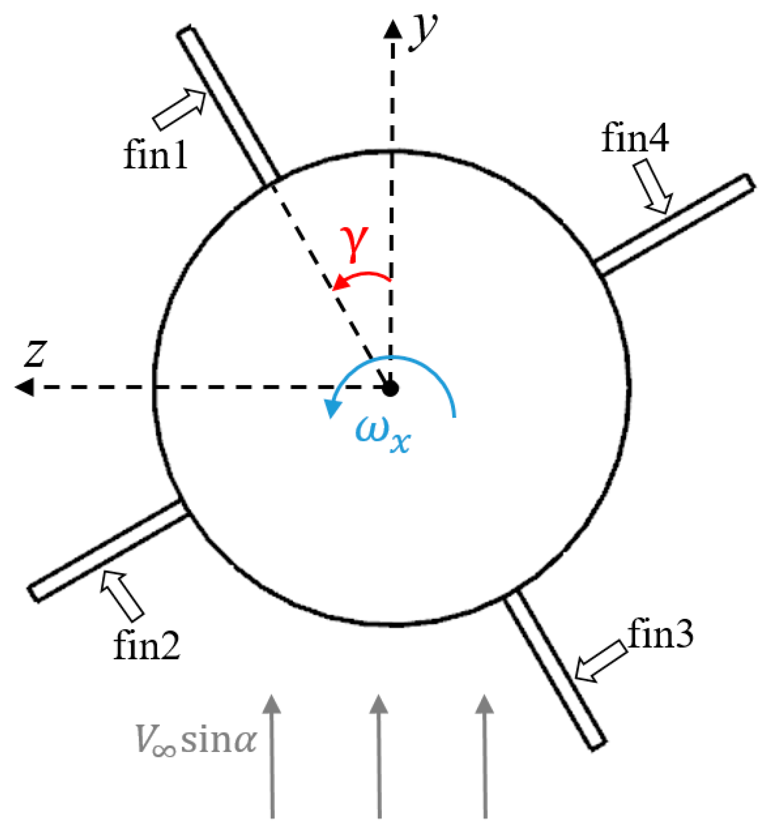
The origin O of the inertial coordinate system, Oxyz, coincides with the initial position of head vertex. The axis Ox is consistent with the longitudinal axis of the projectile, and its positive direction is from the nose to the tail. The axis Oy is located in the vertical plane containing the axis Ox, which is perpendicular to the axis Ox. Its positive direction is upward. The axis Oz and the other two axes form the right−hand coordinate system. Figure 2 shows the spin direction, the fins and the roll angle. The spin is counterclockwise. The leeward fin at the initial time is defined as fin1. The others are defined as fin2, fin3 and fin4 in turn along the spin direction. The angle between the fin1 and the axis Oy is determined as the rolling angle γ .
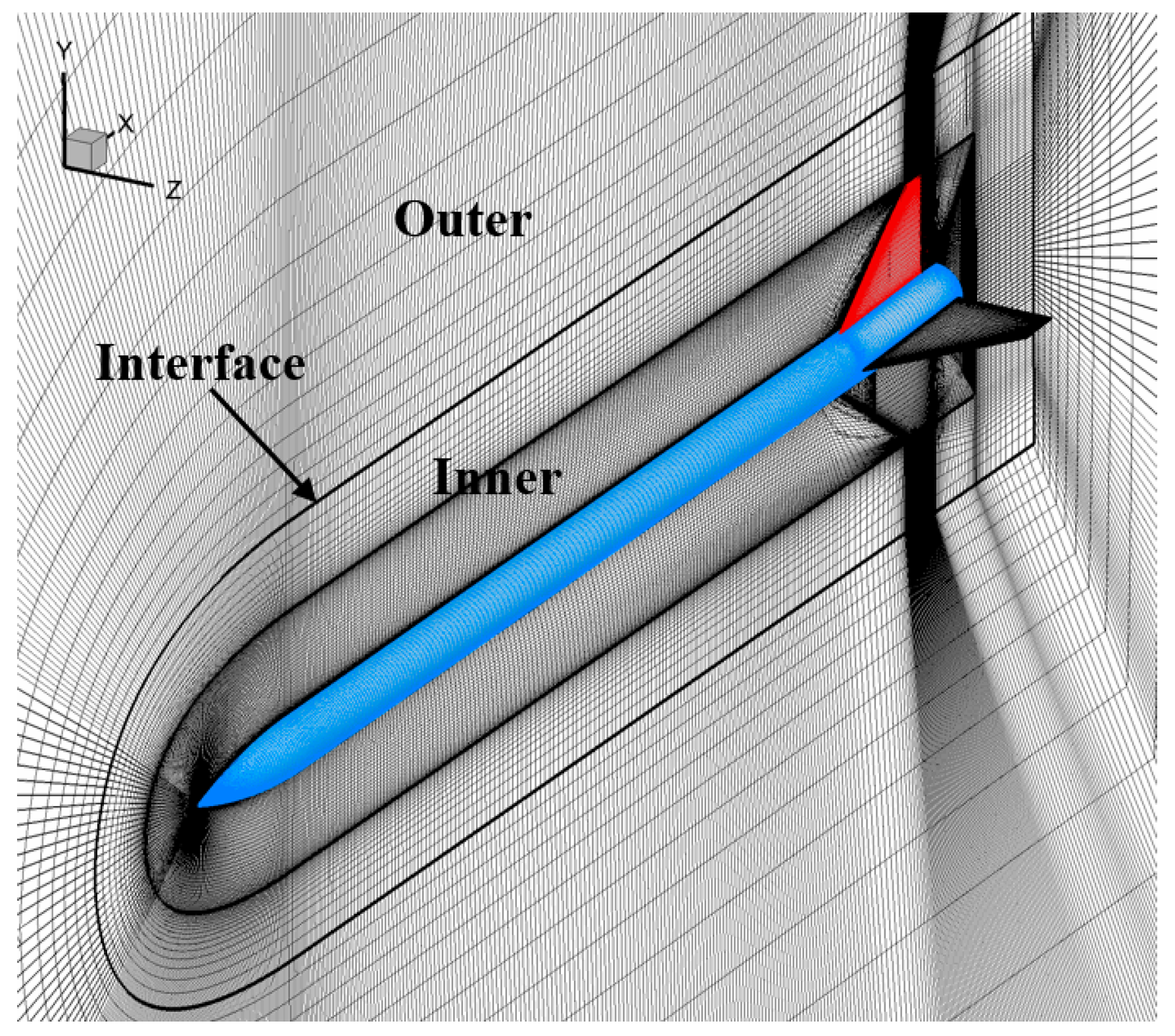
Figure 3 shows the mesh for the flow calculation. The outer domain and the inner domain constitute the whole computational domain, which are connected by the interface. Numerical interpolation is employed at the interface to ensure the flux conservation between the two domains. The dynamic mesh technique is used to adjust the mesh of the inner domain to adapt to the spin and deformation of the projectile, while the mesh of the outer domain remains unchanged. The boundary conditions in the forward and circumferential direction are freestream condition. The boundary in the projectile base direction is set to pressure−outlet. The projectile surface is set to no−slip and adiabatic wall condition.

3. Spin−Deformation Coupling Motion

The structural deformation of projectiles includes the bending and the twisting of the body and fins, which is extremely complicated. In this paper, only the deformation of the body is considered, and that of the fins is ignored. In Figure 4, the spin−deformation coupling motion can be, respectively, decomposed into the spin and deformation. The local coordinate system O x b y b z b is a moving coordinate system whose origin O coincides with the center of the cross section. The direction of the axis O x b is consistent with that of the axis Ox. And, the axis O y b is located in the longitudinal symmetry plane of projectiles, which is perpendicular to the axis O x b . Then, the axis O z b and the other two axes form the right−hand coordinate system. The position of point P ( x 0 , y 0 , z 0 ) at the time t is, respectively, defined as P ( x , y , z ) and P ( x b , y b , z b ) in the Oxyz and O x b y b z b . The relationship between P ( x b , y b , z b ) and P ( x 0 , y 0 , z 0 ) can be expressed as
x b = x 0 y b = y 0 + Δ d t z b = z 0
where Δ d ( t ) represents the deformation of the projectile and is described as
Δ d t = 0 t ψ x , t t d t
where Ψ ( x , t ) denotes the deformation law of the projectile. By the coordinate transformation, it is obtained as
x y z = 0 1 1 1 cos γ sin γ 1 sin γ cos γ x b y b z b
Equations (1)–(3) are the mathematical description for the spin−deformation coupling motion.
Generally, the bending shape of the projectile is mainly manifested as its first order mode shape [21]. Thus, the separation variable method can be exploited to obtain the deformation law of the projectile as
ψ x , t = H t Θ x
where H ( t ) is the variation of deformation with time; and Θ ( x ) denotes the first order mode shape. To simplify the calculations, the H ( t ) is written as
H t = A sin 2 π f t + Δ θ
where A is the deformation amplitude. Δ θ represents the initial phase, Δ θ [ 0 , 90 ° ] . F denotes the frequency, which is equal to the spinning frequency of the projectile. Hence, the deformation law of the projectile is expressed as
ψ x , t = A sin 2 π f t + Δ θ Θ x
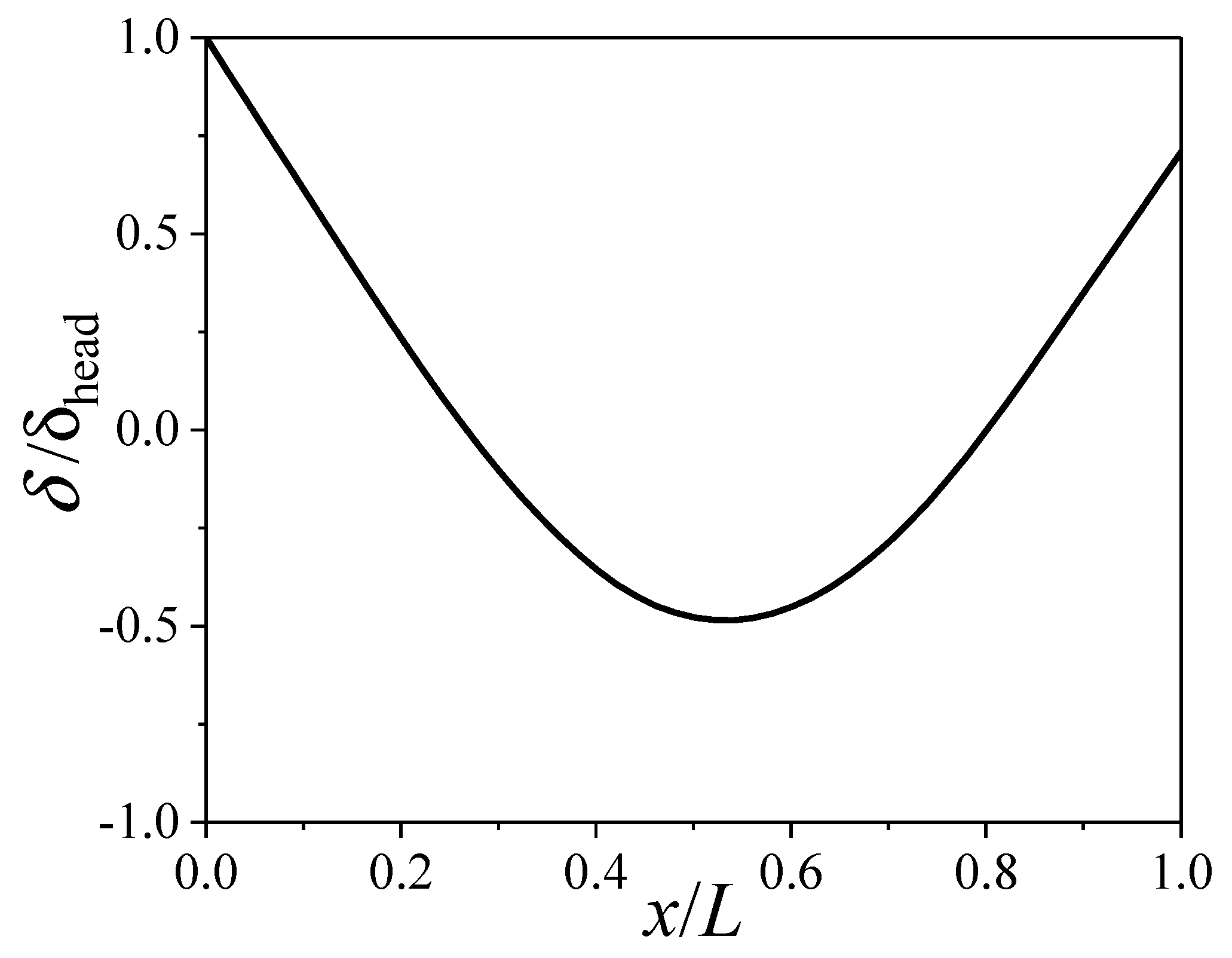
The first order mode shape of the Apache obtained by modal analysis is plotted in Figure 5. Here, δ h e a d denotes the deformation of the head vertex. Once Equation (6) is determined, Equations (1)−(3) can be solved using the numerical method.
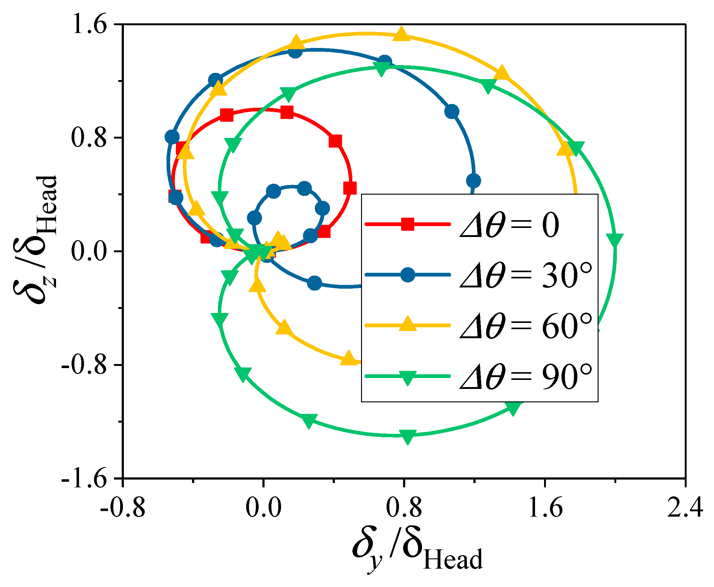
The spin−deformation coupling motion trajectories are showed in Figure 6. In the figure, the δ y and δ z are the longitudinal and lateral components of the spin−deformation coupling motion, respectively. It is seen that the motion trajectory is an ellipse when Δ θ = 0 ° , while the trajectory is the heart shape for Δ θ = 9 0 ° . When Δ θ ( 0 , 90 ° ) , the trajectory gradually changes from an ellipse to a heart shape. For convenience, the motion trajectory is defined as Ω Δ θ ( Δ θ [ 0 , 90 ° ] ). For example, Ω 0 represents the elliptical motion trajectory, while Ω 90 is the heart−shaped motion trajectory. Moreover, when the projectile does not deform (i.e., A = 0 ), the trajectory is defined as Ω . Remarkably, since Ω 0 is axisymmetric about the y axis, the time−averaged value of Ω 0 along the y axis is zero, and the induced time−averaged additional angle of attack is also zero. Similarly, Ω 90 is axisymmetric about the z axis, so the induced time−averaged additional sideslip angle is also zero.

4. Numerical Method

For flow simulation, both large eddy simulation (LES) and URANS are available methods. The fundamental idea of LES is to directly simulate larger eddies that significantly contribute to the overall flow behavior, while modeling or filtering out smaller eddies that are dissipative and have less impact on the overall flow characteristics [27]. LES can capture fine−scale flow features, thus enhancing its predictive precision for turbulence characteristics. Nonetheless, LES often demands fine grid resolutions, leading to a substantial increase in computational costs and the demand for computing resources.
In contrast, URANS significantly reduces the computational cost by computing time−averaged solutions of the Navier–Stokes equations to predict the mean behavior of fluid flow [27]. Moreover, URANS typically necessitates specific grid density near the wall, while maintaining a relatively looser grid in other regions. Although it may not accurately capture fine−scale turbulent features, URANS can yield reasonable and reliable results in practical engineering applications. In fact, URANS is widely used in aerospace engineering to simulate the flow around aircraft, projectiles and other aerodynamic bodies due to its ability to provide a reasonable compromise between computational cost and accuracy for predicting lift, drag and other aerodynamic coefficients [28,29]. Therefore, URANS is adopted in this study.

4.1. Governing Equations and Turbulence Model

In order to precisely simulate the unsteady flow generated by the spinning projectile with deformation and to assess alterations in the lateral force, the integral form of the three−dimensional URANS equations is adopted as the governing equation, as follows:
t Ω W d V + Ω F G n d S = Ω H d V
where Ω is the control volume. Ω and n represent the boundary and the outer normal direction of the control volume. t is the physical time. H is the source terms, which maintains zero in this study. W, F and G, respectively, denote the conserved variables, the convective terms, and the viscous terms, which are expressed as
W = ρ ρ u ρ E , F = ρ u u g ρ u u u g + p I ρ E u u g + p u , G = 0 σ T σ T u + q
where the stress tensor σ T is expressed as
σ T = μ u + u T 2 3 u I
where u denotes the fluid velocity vector. u g denotes the velocity of mesh induced by the spinning motion and bending deformation, which is determined by the dynamic mesh technology. q is the heat flux.   ρ , p,   μ and E are, respectively, the density, the pressure, the dynamic viscosity and the total energy per unit mass.
The shear−stress transport (SST) k ω turbulence model proposed by Menter [30] is employed to calculate the flow of the deformed spinning projectiles. Besides the free flow independence of the k ε model in the far field, it effectively utilizes the robustness and accuracy of the k ω model in the near−wall field [3]. Moreover, the turbulent viscosity in the SST k ω model is modified to involve the transport of turbulent shear stress. Consequently, the SST k ω model is competent to simulate the flow around a deformed spinning projectile.

4.2. Dynamic Mesh Method

In this paper, the spinning motion and bending deformation are involved for the simulation. Therefore, the dynamic mesh method is exploited to adjust the mesh in the fluid domain. The rigid−motion mesh method is employed to treat the mesh motion caused by the rigid motion, while the RBF mesh deformation method is used to solve the morphed boundary due to the bending deformation.

4.2.1. Rigid−Motion Mesh Method

For the rigid−motion mesh method, the mesh is updated based on the translation and rotation of the rigid body. It can ensure the topological structure and the quality of the mesh with great computational efficiency.
Defining r 0 = x 0 , y 0 , z 0 T as the initial position of mesh node P, and the position r m = x m , y m , z m T of mesh node P determined by the rigid motion at any time can be described as
r m = r 0 + Δ r tran + Δ r rot
where r t r a n is the displacement caused by the translation, which is consistent with that of the centroid; r r o t represents the displacement caused by the rotation, and its expression is
Δ r rot = T ( r 0 r cg ) ( r 0 r cg )
where r c g is the centroid position. T represents the transformation matrix, which can be written as
T = 1 0 0 0 cos γ sin γ 0 sin γ cos γ cos θ 0 sin θ 0 1 0 sin θ 0 cos ϕ cos φ sin φ 0 sin φ cos φ 0 0 0 1
where γ , θ and φ , respectively, denote the rolling angle, pitching angle and yawing angle.

4.2.2. RBF Mesh Deformation Method

By employing the RBF mesh deformation method proposed by de Boer et al. [31], the boundary deformation will be diffused to the interior mesh nodes in the fluid domain. Generally, the matrix equations whose dimensions are equal to the number of mesh nodes in the boundary are needed to solve for the RBF mesh deformation method. Hence, the computational cost is very high for a large number of mesh nodes in the boundary. In order to improve the computational efficiency, the RBF mesh deformation method based on dynamic control points in Ref. [32] is adopted to reduce computational cost with a strong robust.

4.3. Discretization Methods

The dual−time stepping method [33] not only guarantees precise computational outcomes but also significantly enhances the computational efficiency. Accordingly, the present study adopts the dual−time stepping method to address the unsteady flow. An unsteady preconditioning [34] is usable when applying the dual−time stepping method. This approach aims to boost the accuracy of the solution by refining the scaling of artificial dissipation. Additionally, it seeks to optimize computational efficiency by optimizing the number of sub−iterations needed during each time step. Here, a preconditioned pseudo−time−derivative term is introduced into Equation (7), as follows:
Γ τ Ω Q d V + t Ω W d V + Ω F G n d S = Ω H d V
where τ denotes the pseudo−time employed in the time−marching procedure. Γ and Q, respectively, denote the preconditioning matrix and the primitive variables [35].
The spatial discretization employs the second−order upwind scheme. Within this scheme, the face value ξ f is determined through the following expression:
ξ f = ξ + Δ ξ r
where ξ and ξ , respectively, represent the value at the cell center and its gradient in the upstream cell. r signifies the displacement vector from the upstream cell centroid to the face centroid.
The time discretization uses the second−order time integration scheme. The specific formula for this scheme is expressed as:
3 χ n + 1 4 χ n + χ n 1 2 Δ t = L χ
where χ represents a scalar quantity. Δ t is the time step. The function L encompasses the spatial discretization.

5. Validation of Numerical Method

5.1. Grid Independence

The grid independence research is carried out by utilizing the two types of grid with different amounts. The specific grid parameters are shown in Table 1. The topologies of the two type grid are the same, but their amounts are, respectively, 6.47 million and 12.82 million. The incoming Mach number is Ma = 3.0, the angle of attack is α = 12 ° and the Reynolds number is R e L = 1.54 × 10 7 . The spin parameter ω ¯ ( ω ¯ = ω x d / 2 V ) is 0.11, and the time step is chosen as T = 1 × 10 5 s . Moreover, the spin−deformation coupling motion trajectory is Ω 0 , shown in Figure 6.
Table 2 displays the relative difference of time−averaged aerodynamic coefficients obtained by the two type grid. The values of the time−averaged normal force coefficient C n and the pitching moment coefficient C m z at different grids are similar, with the relative difference being less than 0.2%. Moreover, the relative difference between the time−averaged lateral force coefficient C z and the time−averaged yaw moment coefficient C m y under different grids is within 8%. Obviously, the calculation results using the two types of different grids are almost the same, which satisfies the grid independence. Therefore, the coarse mesh is determined to simulate the flow for the large−aspect−ratio projectile undergoing spin−deformation coupling motion due to its high computational efficiency.

5.2. Time Step Independence

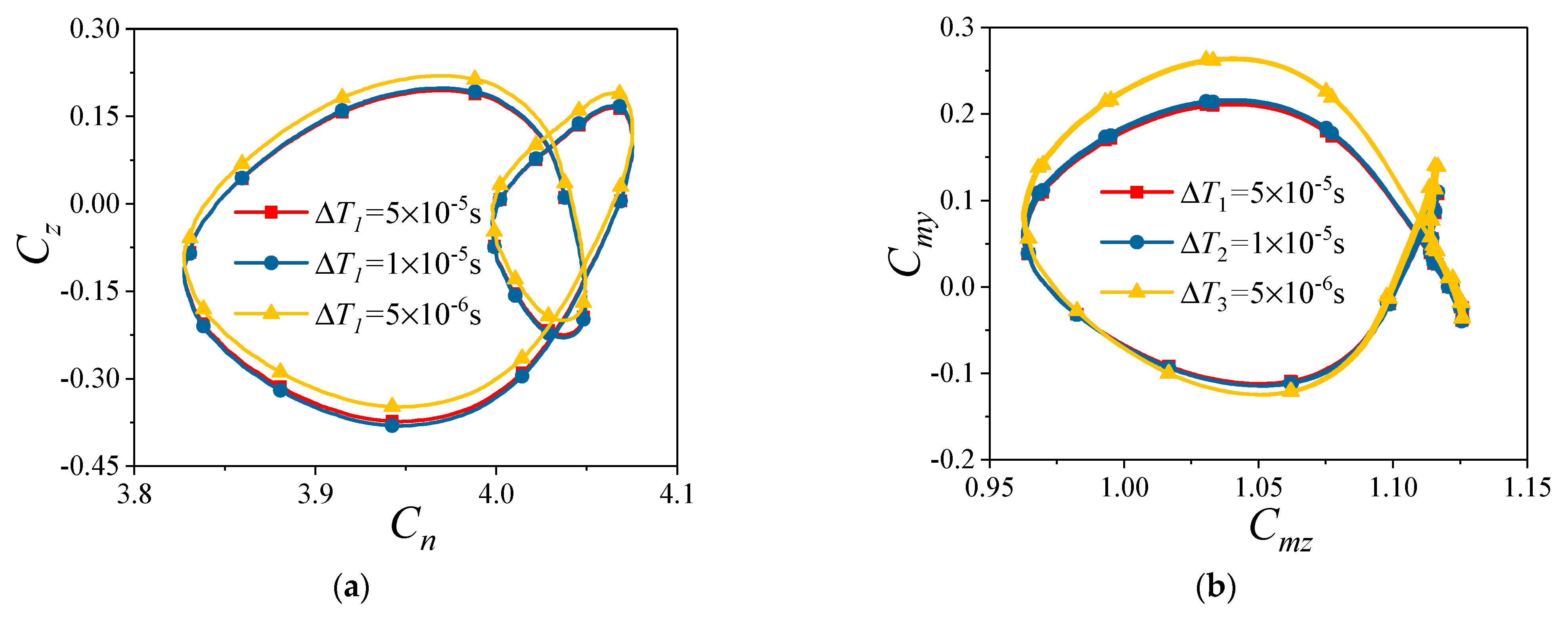
The coarse mesh is used for the validation of time step independence. Three time steps are set to T 1 = 5 × 10 5   s , T 2 = 1 × 10 5   s and T 3 = 5 × 10 6   s . The other calculation conditions are consistent with those in Section 5.1. Figure 7 indicates the aerodynamic coefficients obtained within a spin cycle at different time steps. It can be observed that the difference between the results calculated at T 2 and T 3 is small, while the results obtained at T 1 are significantly different from those calculated at T 2 and T 3 . Therefore, the time step for the numerical calculation is chosen as T 2 .

5.3. Comparison Validation

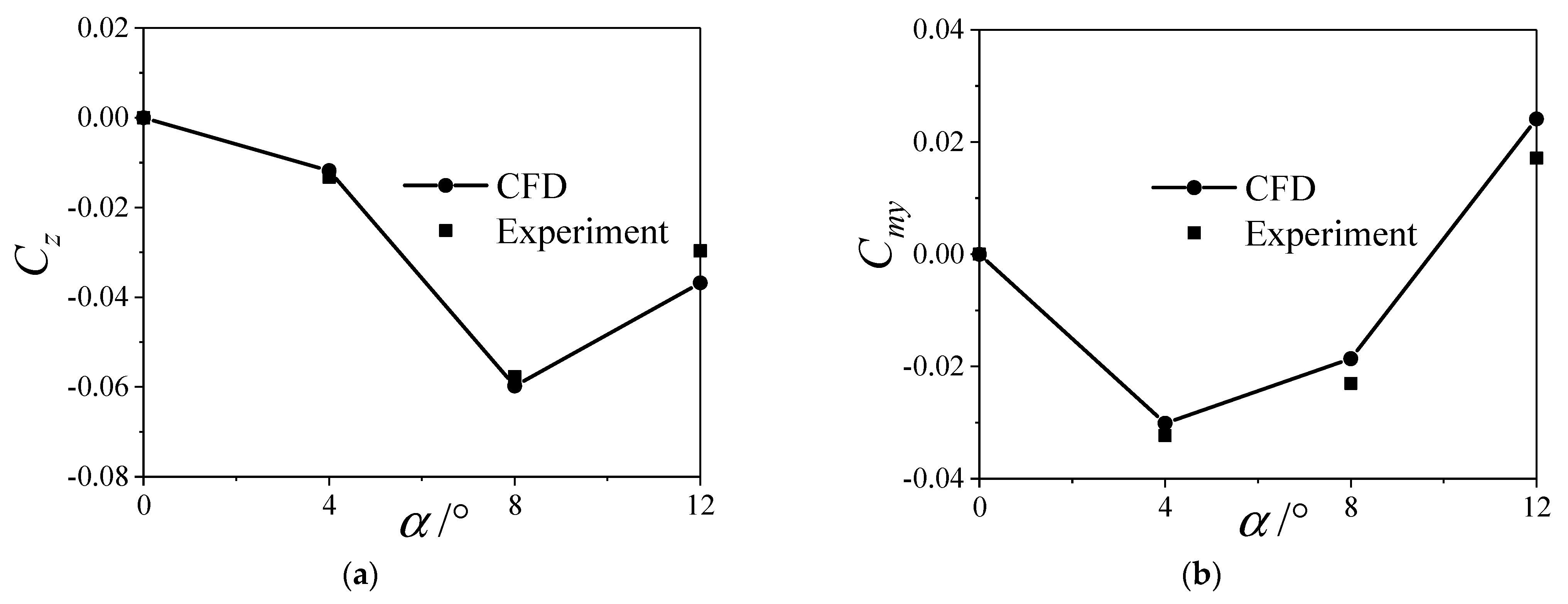
The experiment data in Ref. [36] is exploited to validate the numerical method. The number of grids is approximately 6.5 million. The computational conditions are Ma = 3.0, ω ¯ = 0.11 and R e L = 1.54 × 10 7 . Figure 8 shows the comparison between the CFD−based numerical results and the experimental ones. It can be seen that the time−averaged lateral force coefficient C z and yaw moment coefficient C m y , obtained by numerical calculation, are in good agreement with the experimental data. Therefore, the numerical method can be employed to simulate the flow for spinning projectiles with large aspect ratios.
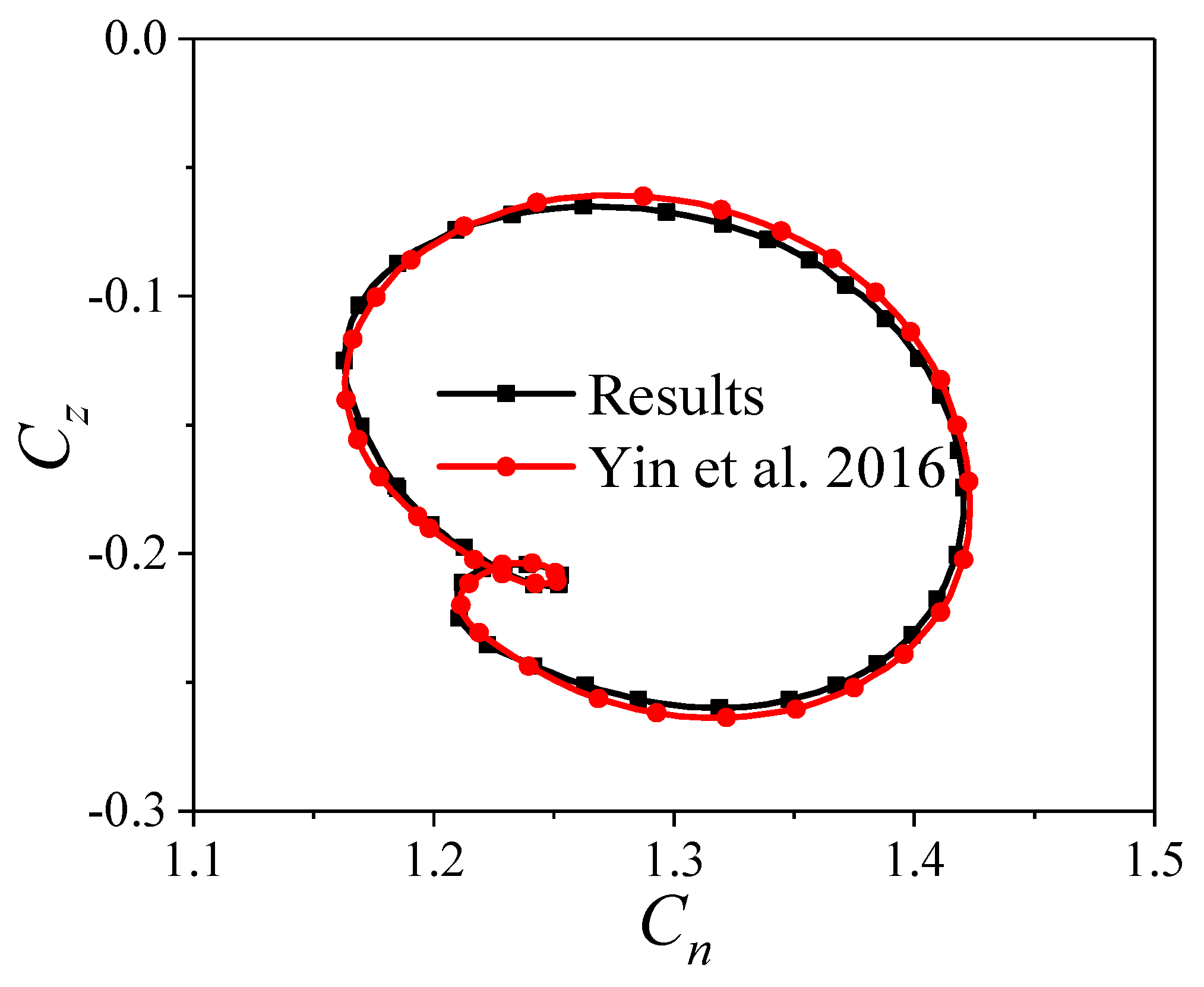
In order to further verify the accuracy, the numerical method proposed in this paper is used to compute the aerodynamic characteristics of a spinning projectile with elastic deformation as outlined in Ref. [3]. This computation adheres to the original author’s specified conditions, encompassing Ma = 3.0, α = 15 ° , R e L = 5.8 × 10 7 and ω ¯ = 0.283 . Figure 9 gives the comparison between the numerical result obtained in this paper and that obtained in Ref. [3]. This comparison reveals a strong agreement between the two, providing additional confirmation of the accuracy of the numerical method presented in this paper.

6. Effect of Deformation on Lateral Force

The reference length is the length of the Apache. The relative position X ¯ c g of the centroid and the head vertex before the engine working is 0.54 [36]. However, after the engine work is completed, the centroid is moved forward by 10% relative to the initial position. Thus, X ¯ c g is determined as 0.44 in this paper. The other computational conditions are determined as shown in Table 3, unless otherwise specified. On this basis, the flow is simulated when the projectile undergoes spin ( Ω ) and the spin−deformation coupling motion ( Ω Δ θ , Δ θ [ 0 , 90 ° ] ). The specific trajectory shape of Ω Δ θ is shown in Figure 6.

6.1. The Variation with Trajectory

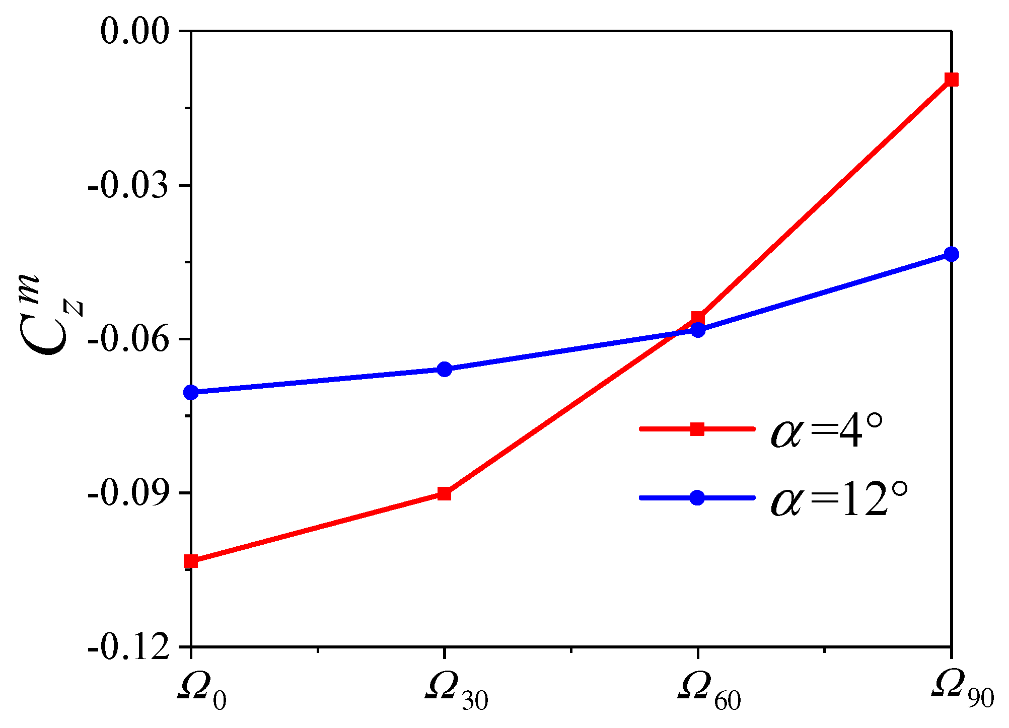
Figure 10 exhibits the variation of the time−averaged lateral force coefficient C z m for the projectile with the trajectory Ω Δ θ . As shown in Figure 10, the value of C z m decreases continuously with the trajectory changing from Ω 0 to Ω 90 at the different angles of attack α . That is, the value of C z m is the largest when the trajectory is Ω 0 , while it is the smallest for the Ω 90 .
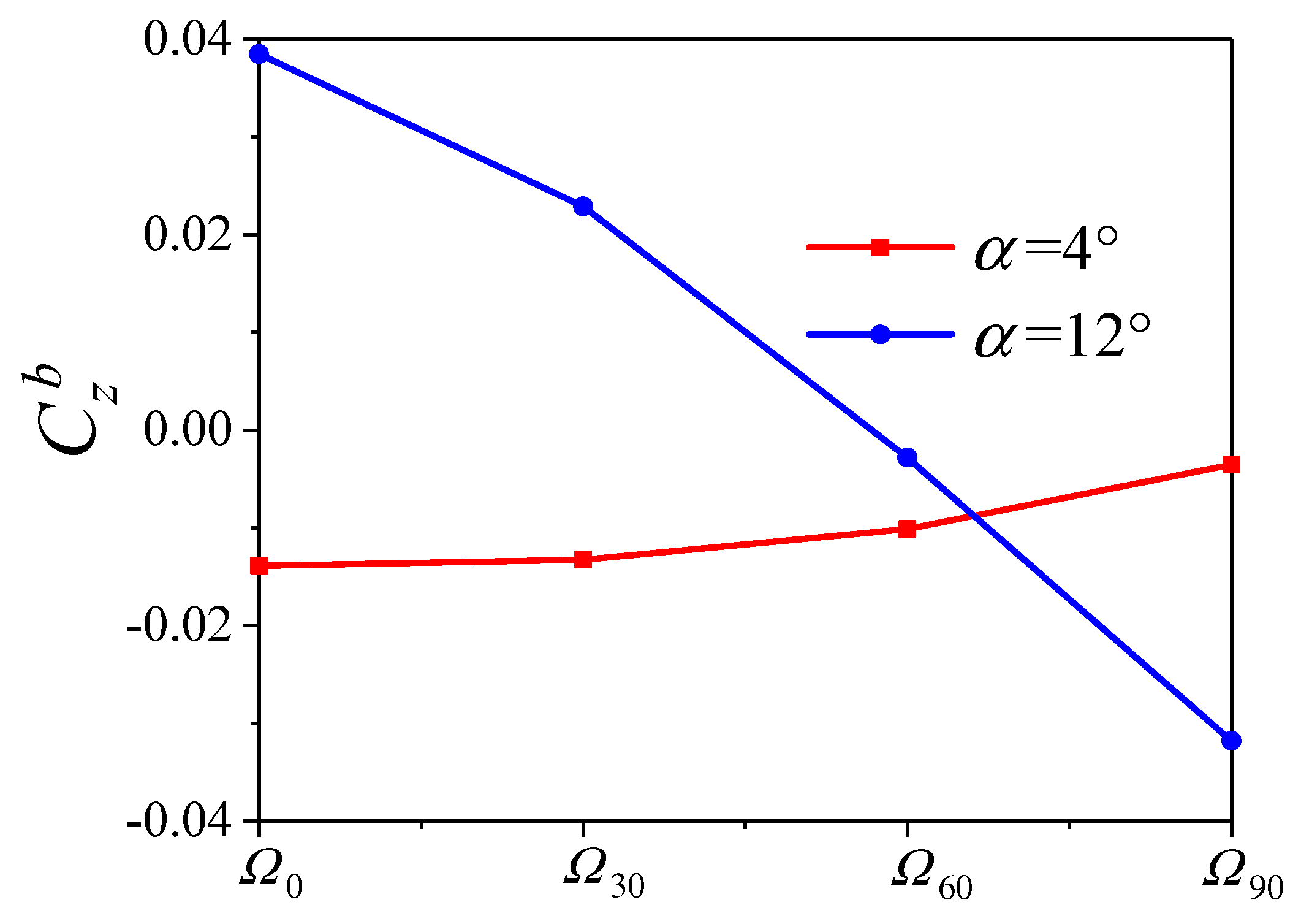
Figure 11 shows the variation of the time−averaged lateral force coefficient C z b for the projectile body with the trajectory Ω Δ θ . It is found that as the trajectory changes from Ω 0 to Ω 90 , the variations of C z b and C z m are similar at α = 4 ° , while their trends are opposite at α = 12 ° . However, it is worth noting that the extreme values of C z b and C z m are all obtained when the trajectory is Ω 0 or Ω 90 . Therefore, the following will focus on the analysis of the lateral force when the trajectory is Ω 0 or Ω 90 .

6.2. The Variation with Angles of Attack

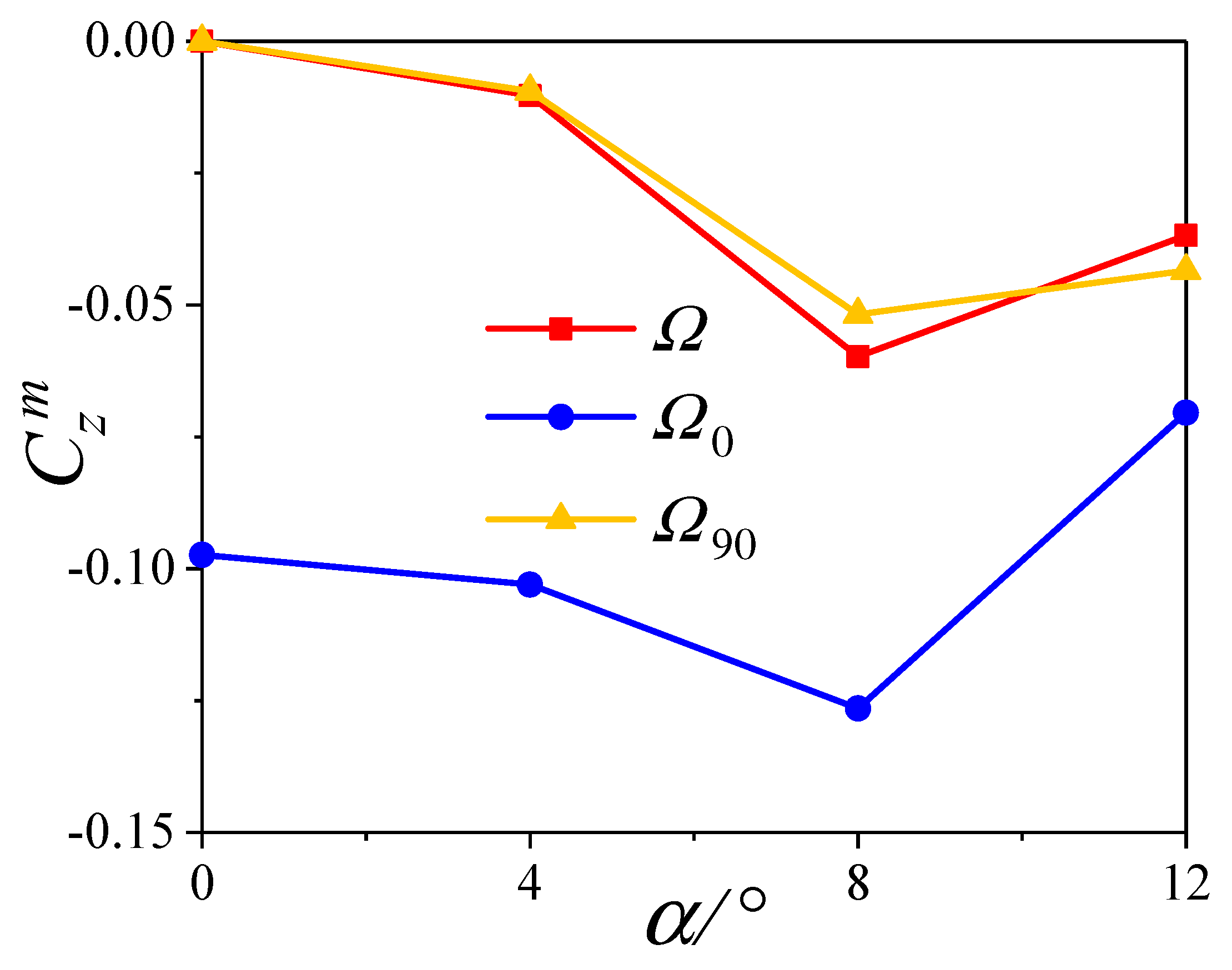
Figure 12 exhibits the variation of the time−averaged lateral force coefficient C z m for the projectile with angles of attack α at different trajectories. As shown in Figure 12, the variation of C z m is similar at different trajectories, which increases first and then decreases with α . When the trajectory is Ω 0 , the value of C z m is maximum. Although the induced time−averaged additional sideslip angle is zero for the Ω 90 , the C z m is still changed by the deformation, especially at large α .
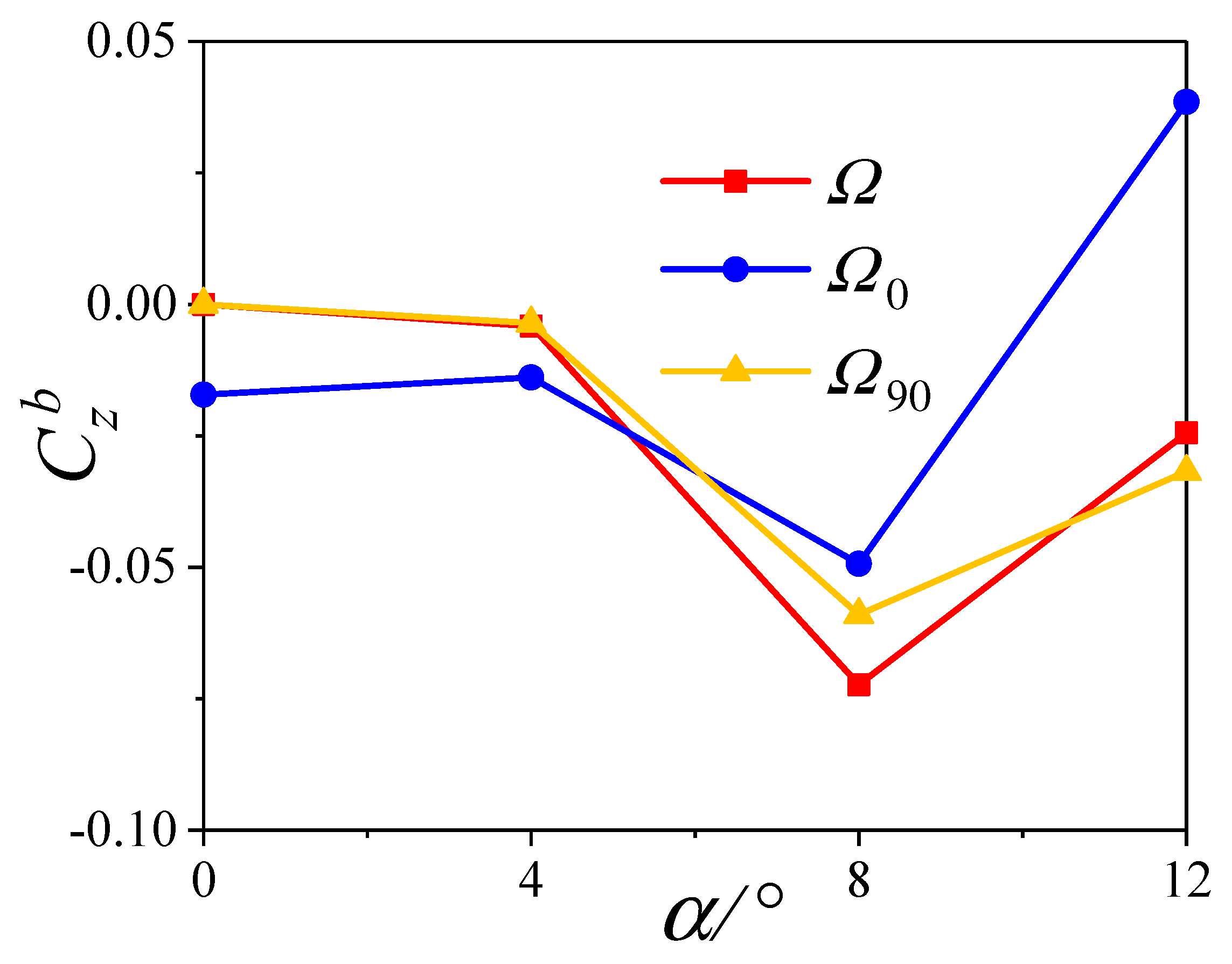
Figure 13 shows the variation of the time−averaged lateral force coefficient C z b for the projectile body with α at different trajectories. It is found that the difference between C z b and C z m is small at the same α when the trajectory is Ω or Ω 90 . Moreover, although the C z m is larger than the C z b at same the α when the trajectory is Ω 0 , the variation of the two is consistent. Thus, the body determines the variation of the time−averaged lateral force coefficient of the projectile with α at different trajectories.
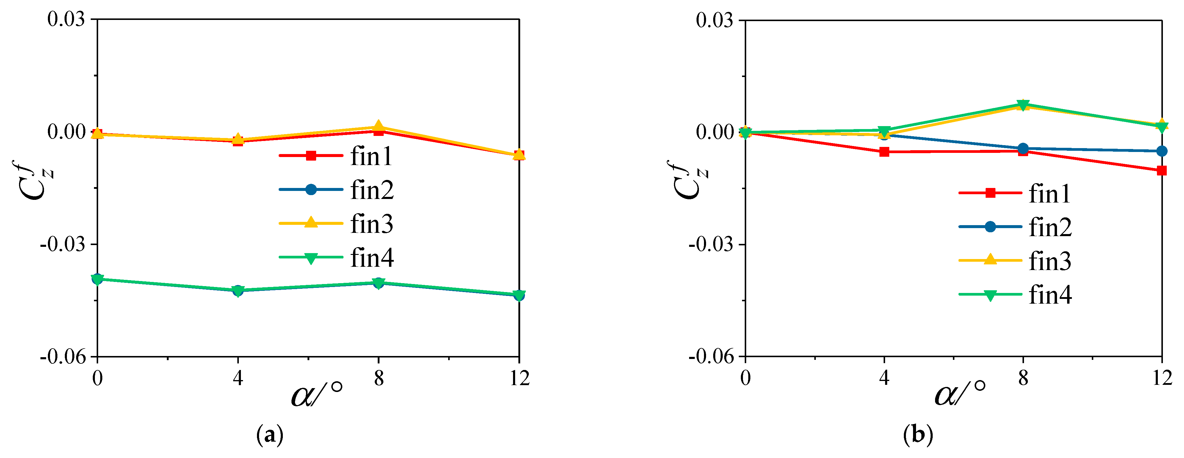
Figure 14 depicts the variation of the time−averaged lateral force coefficient C z f for the fins with α at different trajectories. It is seen that the variation of the C z f for all fins with α is consistent when the trajectory is Ω 0 , while the values of fin2 and fin4 are the largest. When the trajectory is Ω 90 , the C z f of all tails change little around the zero at different α .

6.3. The Variation with Deformation Amplitude

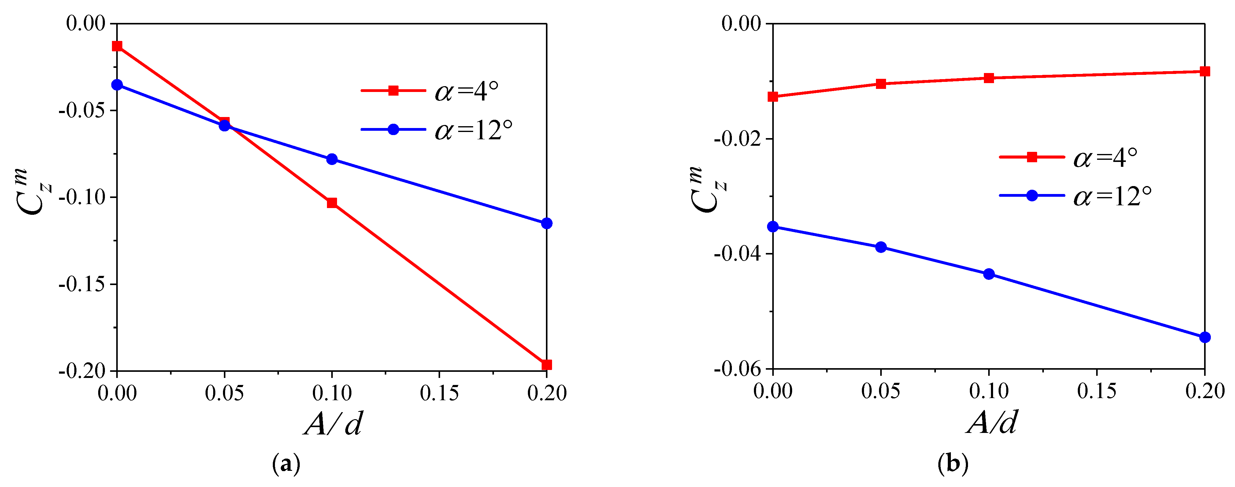
Figure 15 shows the variation of the time−averaged lateral force coefficient C z m for the projectile with the deformation amplitude A. Obviously, the value of the C z m increases linearly with the increase of the A for the Ω 0 . When the trajectory is Ω 90 , the C z m changes nonlinearly with the A, and the trends are different at different α . Specifically, the value of C z m decreases with the increase of the A when α = 4 ° , but the value increases at α = 12 ° .
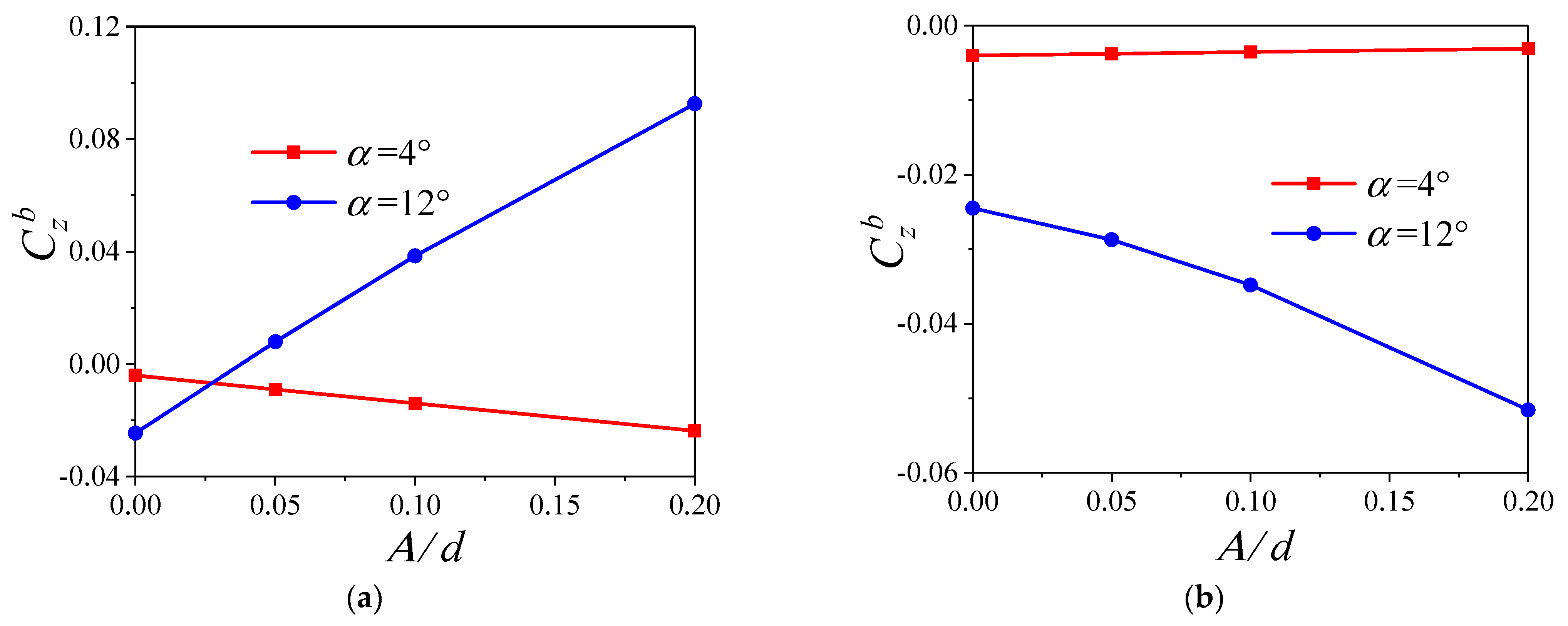
Figure 16 shows the variation of the time−averaged lateral force coefficient C z b for the projectile body with A. It is observed that for the Ω 0 , the value of the C z b increases linearly with the A at α = 4 ° , while it changes from negative to positive and increases continuously with the A when α = 12 ° . When the trajectory is Ω 90 , the variations of the C z b are consistent with that of the C z m in Figure 15b, which are nonlinearly correlated with the A.

7. Mechanism on the Lateral Force Induced by Deformation

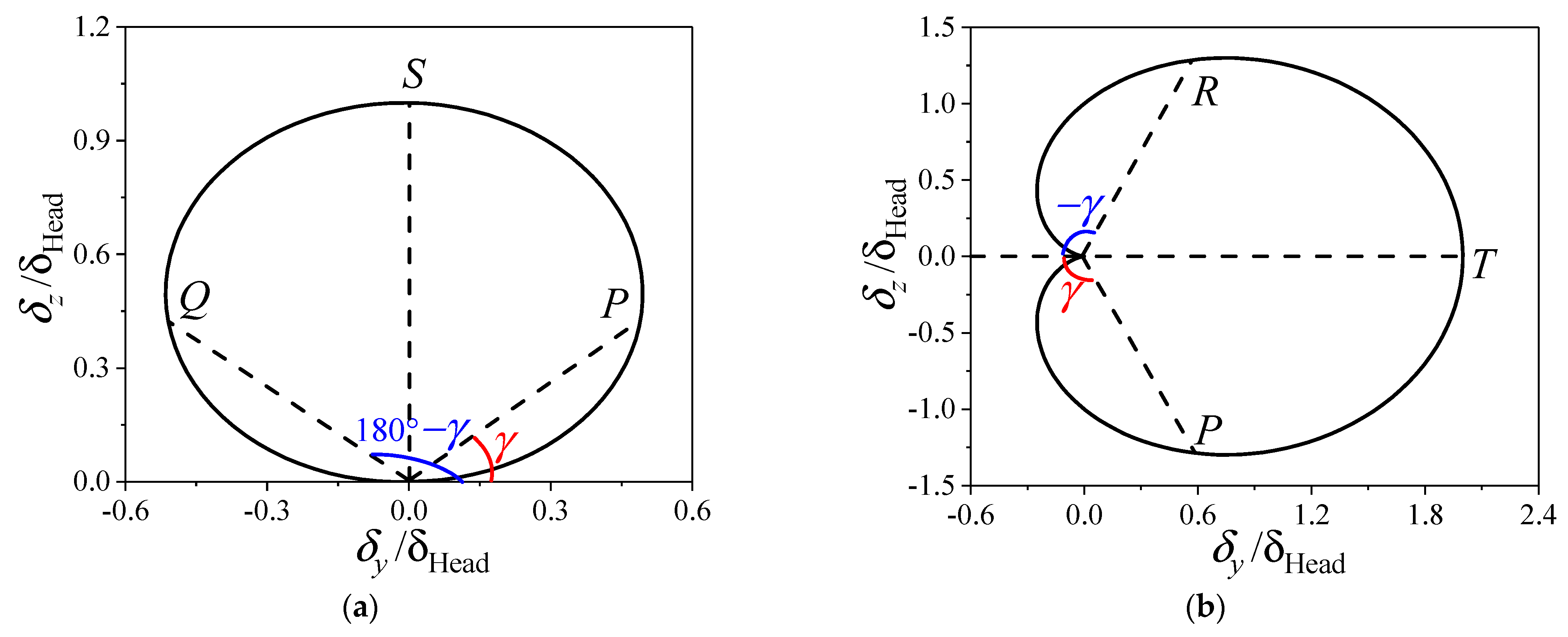
As mentioned in Section 6, the lateral force of spinning projectiles with large aspect ratios is significantly changed due to the bending deformation. In this section, the flow is analyzed for the projectile experiencing the spin−deformation coupling motion, which is exploited to reveal the mechanism for the change of the lateral force. The trajectories and characteristic moment shown in Figure 17 are employed to explore the flow. In Figure 17a, for the Ω 0 , the roll angles at the moments P and Q are, respectively, γ and 180 ° γ . At the moment S, the additional angle of attack is zero. In Figure 17b, when the trajectory is Ω 90 , the roll angles at the moments P and R are, respectively, γ and γ . At the moment T, the additional sideslip angle is zero.

7.1. Compression and Expansion of the Fluid

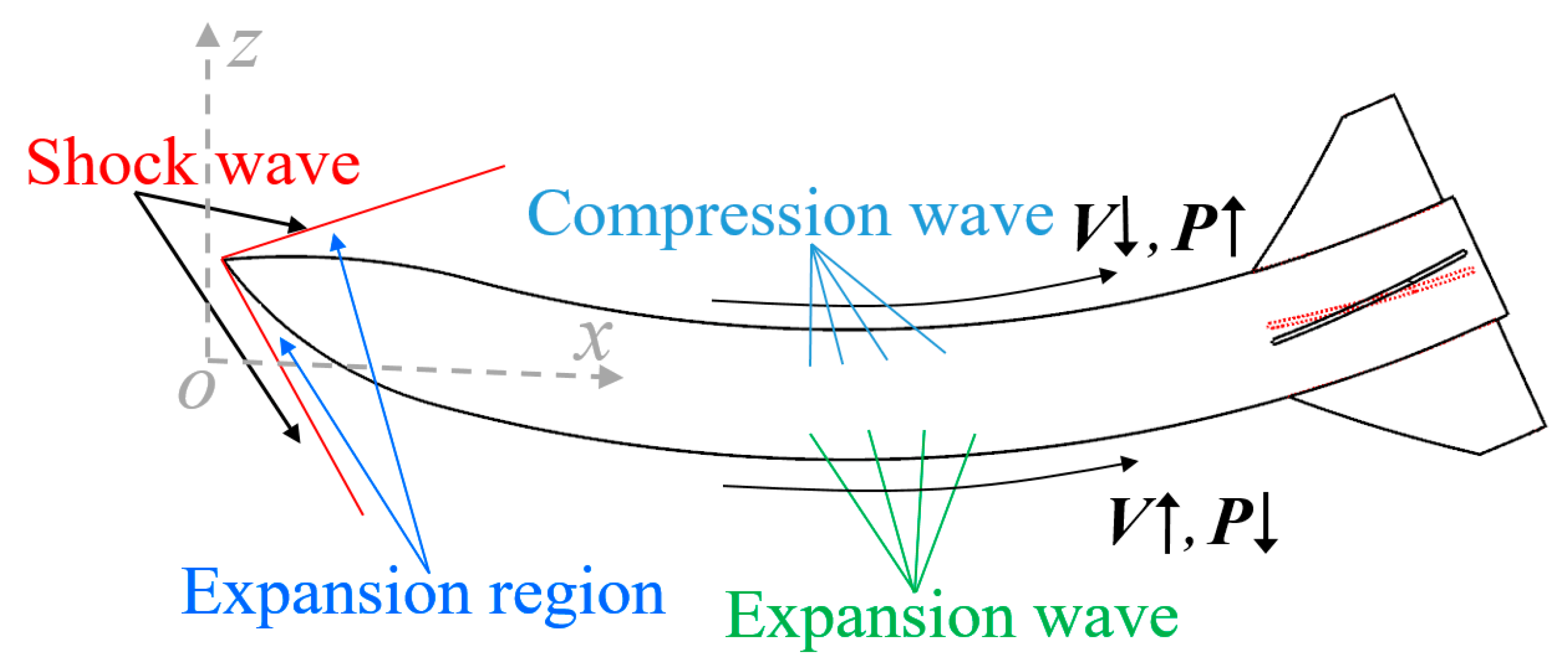
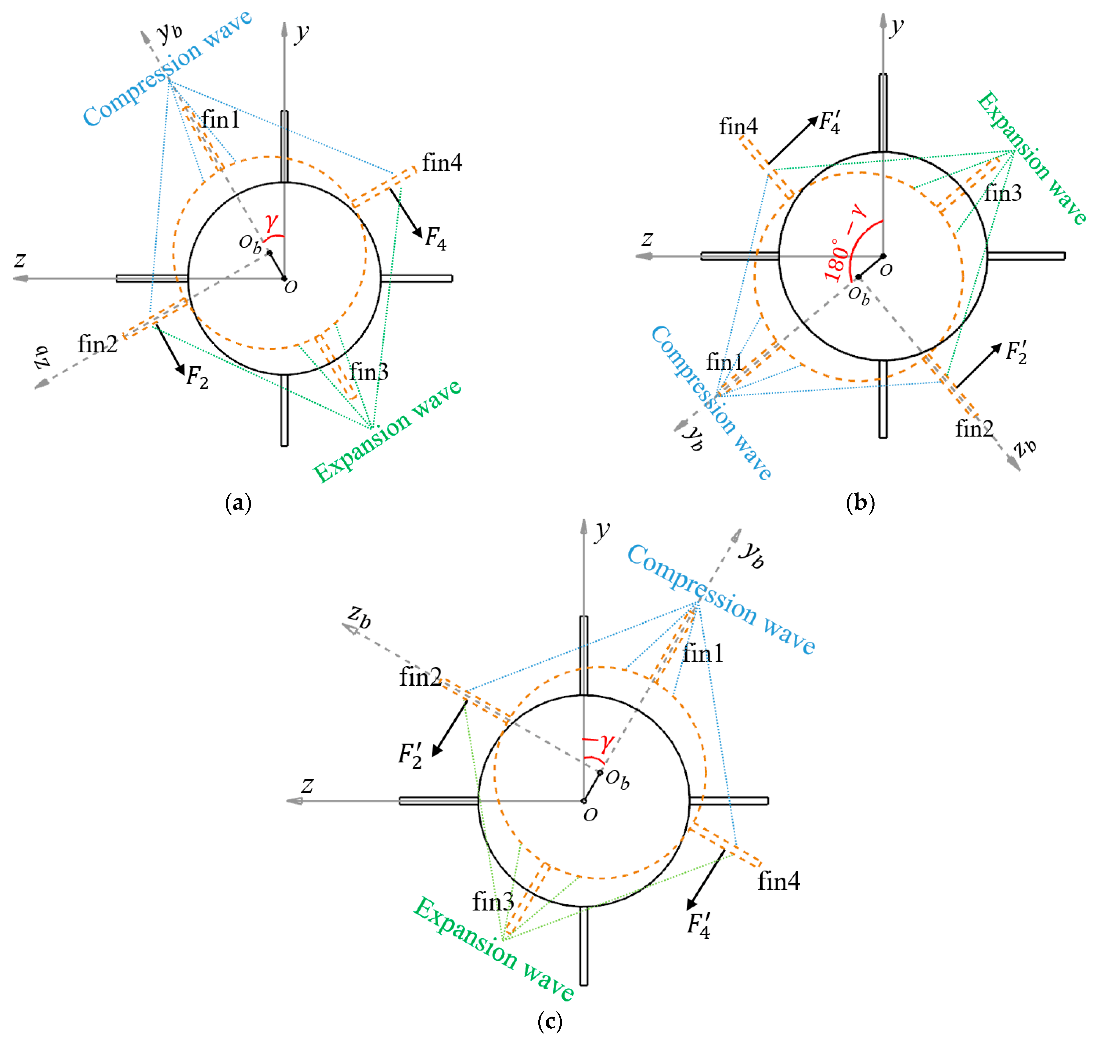
When the projectile deforms, the compression and expansion waves are produced in the axial flow, which affects the aerodynamic characteristics. Figure 18 shows the compression wave and expansion wave induced by the deformation. It is seen that for the projectile with deformation, the high pressure gas after the shock wave continues to expand and accelerate in the head. When it reaches the middle or tail of the body, the compression wave is generated on the concave side of the body, which leads to the decrease of velocity and the increase of pressure for the local airflow. Whereas, the expansion wave is produced on the convex side of the body, which causes the increase of velocity and the decrease of pressure for the local airflow.
Figure 19 shows the effects of the compression wave and expansion wave on the aerodynamic characteristics of the fins. In Figure 19a, affected by the compression wave and expansion wave, a pair of forces F 2 and F 4 with the same direction are generated for the fin2 and fin4 at the characteristic moment P (the roll angle is γ). As shown in Figure 19b, when the trajectory is Ω 0 , there exists the moment Q (the roll angle is 180 ° γ ) where the lateral force only appeared after the superposition of F 2 and F 2 , F 4 and F 4 . As shown in Figure 19c, when the trajectory is Ω 90 , there exists the moment R (the roll angle is γ ) where the normal force only appeared by superimposing F 2 and F 2 , F 4 and F 4 . Moreover, the interference of the compression wave and expansion wave on the aerodynamic characteristics of the fins causes the lateral and normal pressure center to move backward, which induces the increase of the pitching moment and yaw moment of the projectile.

7.2. Change of Vortex and Pressure Distribution

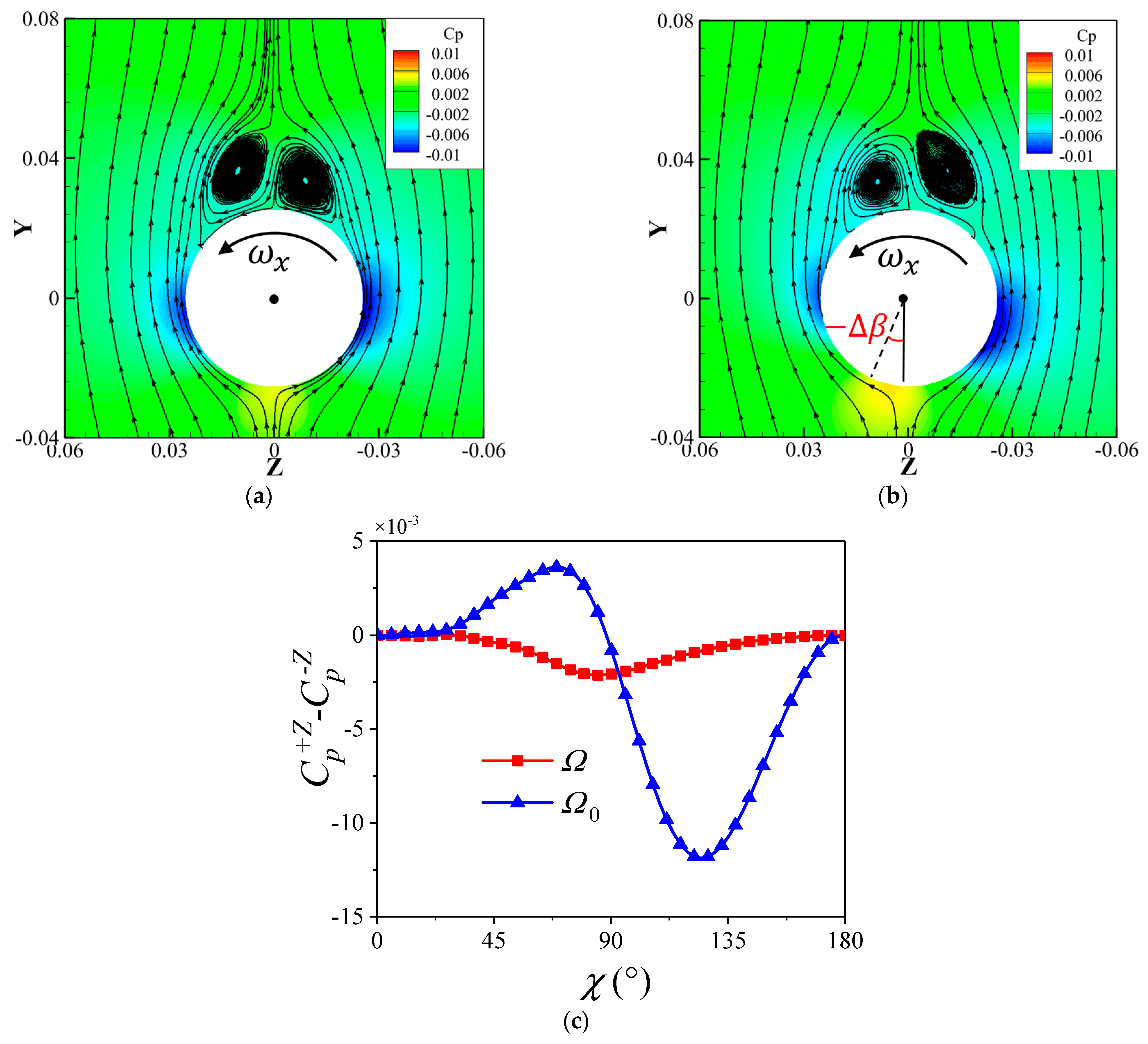
In this section, the effect of the spin−deformation coupling motion on the vortex and pressure distribution is researched to explain the reason for the deformation−induced variation in the lateral force further. For convenience, the circumferential angle χ is defined as shown in Figure 20. The point P is the origin of χ (i.e., χ = 0 ° ), and χ increases gradually along the counterclockwise direction. The value of χ is defined as
χ = χ 0 χ 180 χ 360 180 χ 360

7.2.1. Effect of the Trajectory Ω 0

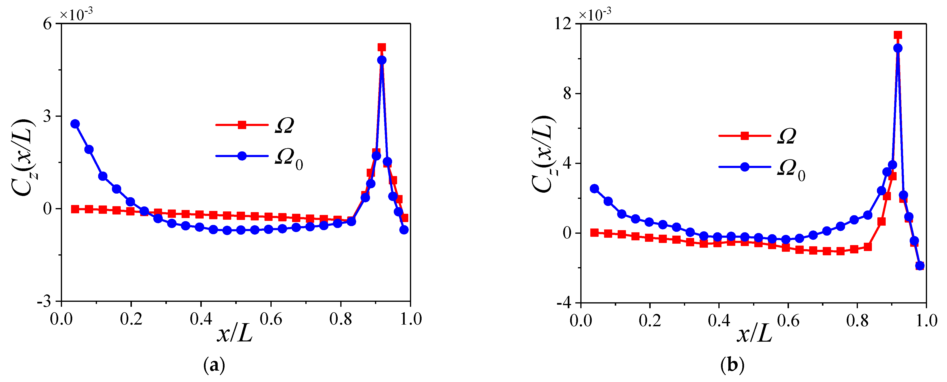
Figure 21 shows the distribution of the time−averaged lateral force coefficient C z ( x / L ) for the Ω and Ω 0 . It is observed that for the Ω 0 , the distribution curves at different α are presented as parabolas when x / L 0.85 . Affected by the fins, the variation of C z ( x / L ) for the Ω and Ω 0 is similar when x / L > 0.85 , which increases first and then decreases. Notably, the C z ( x / L ) for the head of the projectile body is consistent at different α when the trajectory is Ω 0 , which indicates it is only related to the deformation. However, the C z ( x / L ) for the middle or tail is inconsistent, which declares it Is related to the deformation and the flow structures.
Firstly, the mechanism for the lateral force of the head is analyzed. Figure 22 exhibits the variation of the lateral force coefficient C z 0.1 at the cross section x/L = 0.1 when the trajectory is Ω 0 . Meanwhile, the additional sideslip angle β 0 is also shown in Figure 22. Notably, the physical quantities involved are normalized in the figure, namely
Π n t = Π t Π m a x
where   Π ( t ) represents the original physical quantity, and Π n ( t ) is its normalized result. Π m a x denotes the maximum value of Π ( t ) . As shown in Figure 22, the variation of C z 0.1 is completely consistent with that of β 0 at different α , which indicates the lateral force for the head mainly depends on the additional slip angle caused by the bending deformation.
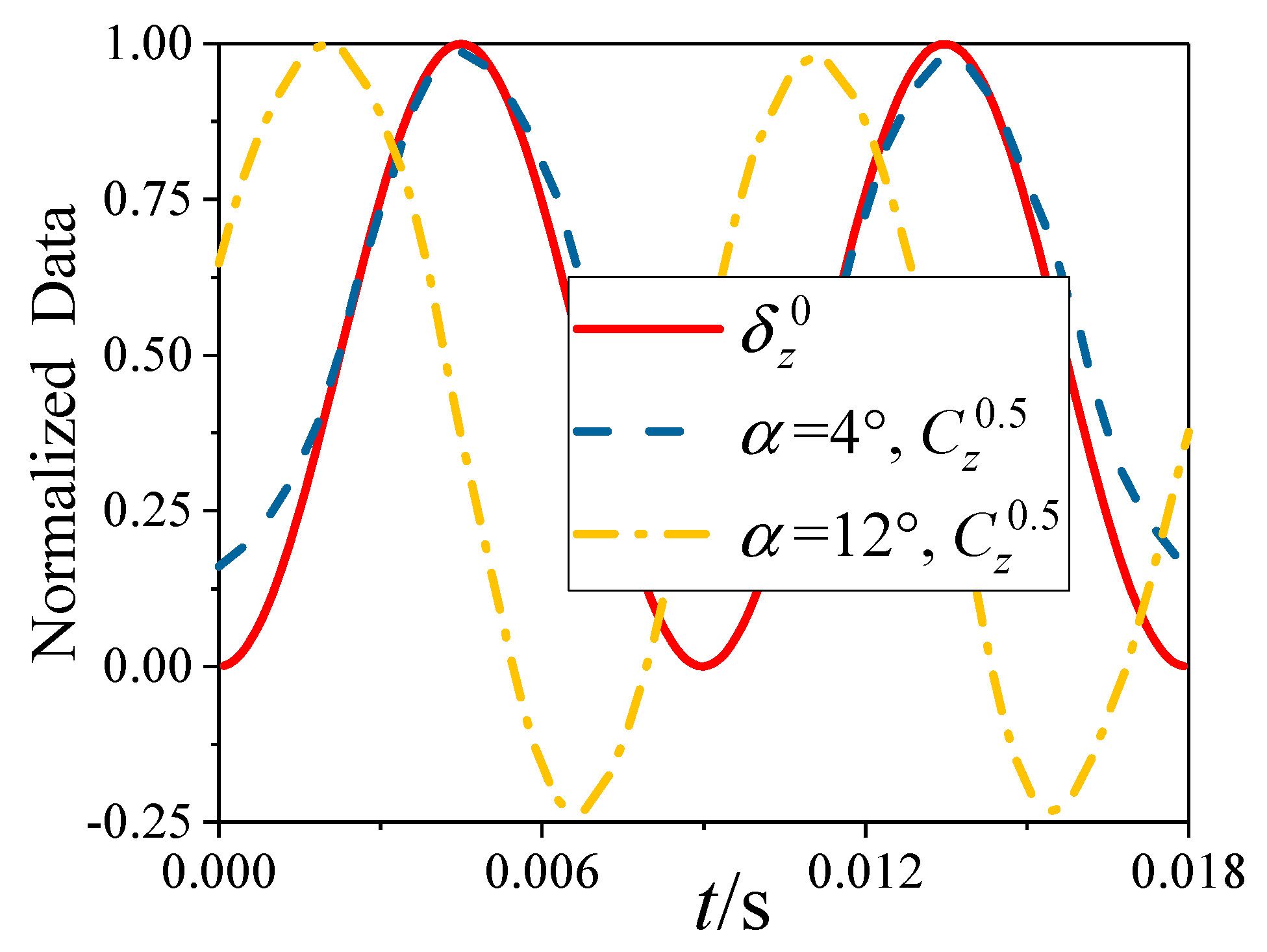
Secondly, the mechanism for the lateral force of the middle is explored. Figure 23 shows the variation of the lateral force coefficient C z 0.5 at the cross section x/L = 0.5 when the trajectory is Ω 0 . Meanwhile, the lateral component δ z 0 of Ω 0 is also shown in Figure 23. As shown in Figure 23, the variation of C z 0.5 at α = 4 ° is consistent with that of δ z 0 , while the variation of the two is different at α = 12 ° . This manifests that the lateral force of the middle is mainly related to the deformation at small α when the projectile deforms, but the influence of deformation is weakened with the increase of α . In fact, as shown in Figure 18, the compression wave and expansion wave induced by the deformation increase the pressure on the concave side of the middle, while the pressure on the convex side is decreased. This asymmetry of the pressure distribution results in the negative lateral force of the middle at small α induced by the deformation. However, it can be seen from Figure 21 that the value of the lateral force of the middle changes little at large α , which indicates that the increase of α will weaken the asymmetry of the pressure distribution.
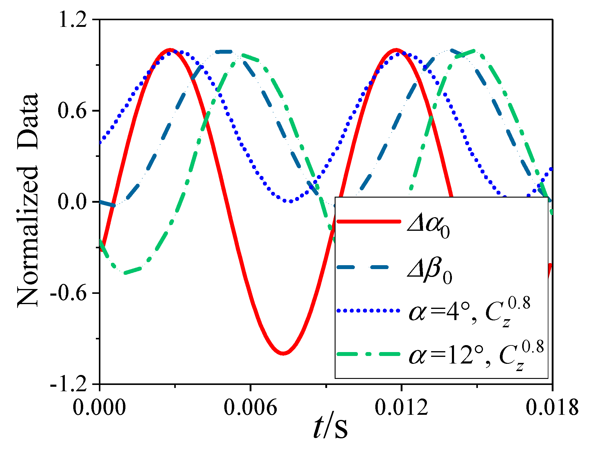
Finally, the mechanism for the lateral force of the tail is discussed. Figure 24 shows the variation of the lateral force coefficient C z 0.8 at the cross section x/L = 0.8 when the trajectory is Ω 0 . Meanwhile, the additional sideslip angle β 0 and angle of attack α 0 are also shown in Figure 24. It is seen that the change trend of the C z 0.8 at α = 4 ° is similar to that of α 0 , which indicates that even if the time−average value of α 0 is zero, it will also affect the generation of the lateral force at small α . The variation of the C z 0.8 at α = 12 ° is similar to that of β 0 , but there exists the characteristic of phase lag between them. The specific flow field is analyzed to further illustrate the mechanism for the lateral force of the tail induced by the deformation in the following.
Figure 25 and Figure 26, respectively, show the pressure contour, streamlines and the pressure difference between the left and right sides of the cross section x/L = 0.8 when α is 4 ° or 12 ° . As shown in Figure 25, the change of pressure difference within χ ( 0 ° , 40 ° ) is very small, which indicates that the change of the separated vortex induced by the deformation has little contribution to the lateral force at small α . When the trajectory changes from Ω to Ω 0 , the pressure difference within χ ( 40 ° , 82 ° ) is positive due to the offset of the low−pressure region on the left and right sides. However, the negative pressure difference within χ > 82 ° is induced by the offset of the high−pressure region on the windward side, which plays a leading role in the generation of the lateral force. Therefore, the change of the high−pressure region on the windward side induced by the additional sideslip angle will lead to the negative lateral force of the tail.
Combined with the analysis of Figure 24 and Figure 25, it can be seen that the coupling of the additional angle of attack and spinning motion determines the variation of the transient lateral force of the tail at small angles of attack, while the additional sideslip angle will increase its time−averaged value.
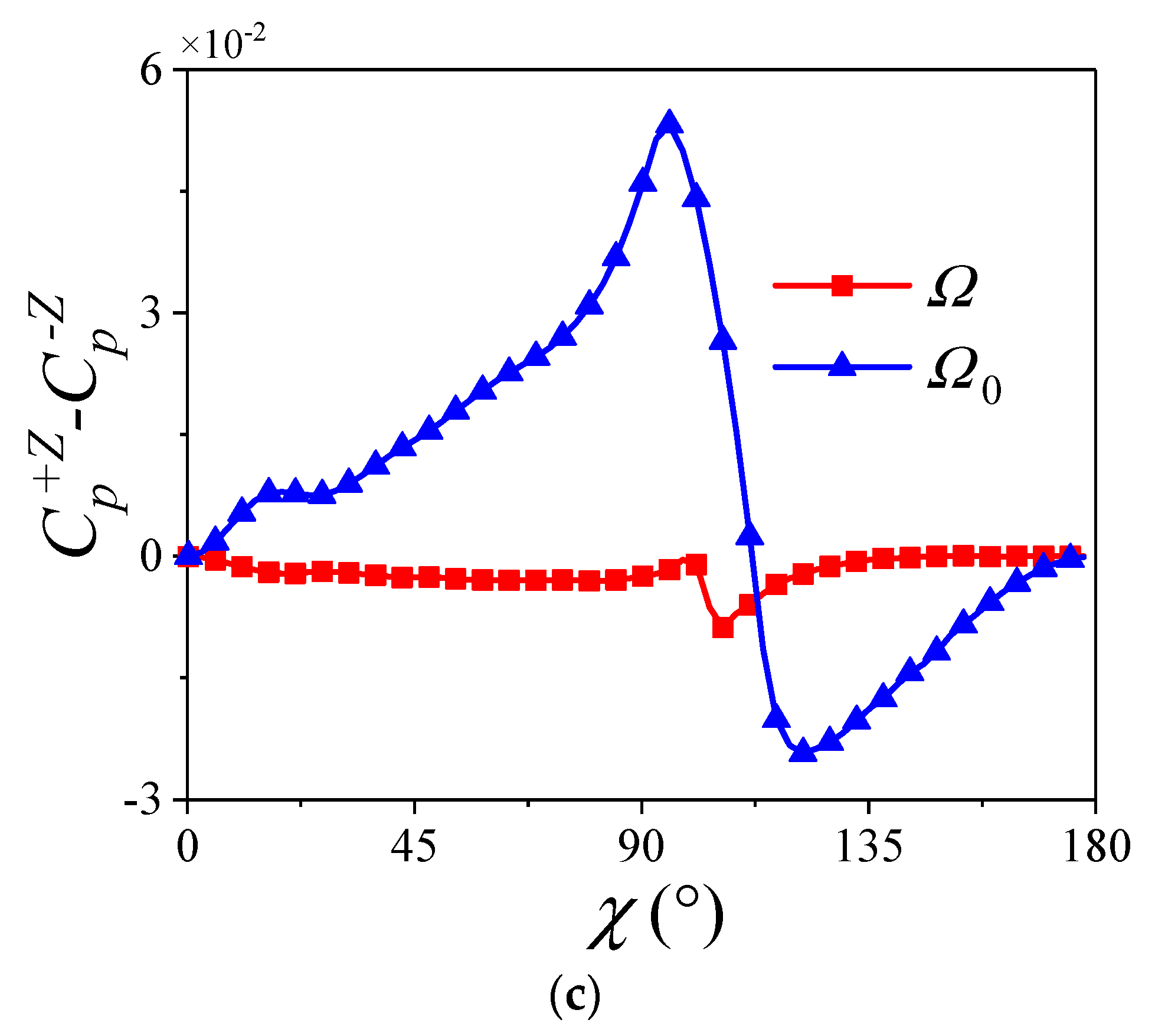
Comparing Figure 25 with Figure 26, the variation of the pressure and vortex system at the cross section x/L = 0.8 under α = 12 ° is similar to that under α = 4 ° when the projectile deforms. However, the separation vortex is stronger when α = 12 ° . Thus, the decreased distance between the left separation vortex and the projectile surface leads to a significant decrease in the pressure for the upper−left of the cross section, while the increased distance between the right separation vortex and the projectile surface results in a noticeable increase for the upper−right. Those lead to the positive pressure difference within χ ( 0 ° , 75 ° ) . Moreover, besides the offset of the low−pressure region on the left and right sides, the obvious decrease of pressure for the low−pressure region on the left side also causes the pressure difference within χ ( 75 ° , 110 ° ) to be continuously positive due to the interference of the separation vortex. Although the offset of the high−pressure region on the windward side leads to the negative pressure difference within χ > 110 ° , it does not take up a leading role in the generation of the lateral force. Hence, the change of the separation vortex is the main cause of the positive lateral force of the tail induced by the deformation at large angles of attack. Moreover, according to the analysis of Figure 24, the change of the separation vortex induced by the deformation can also lead to the phase lag between the transient lateral force and the additional sideslip angle for the tail at large angles of attack.

7.2.2. Effect of the Trajectory Ω 90

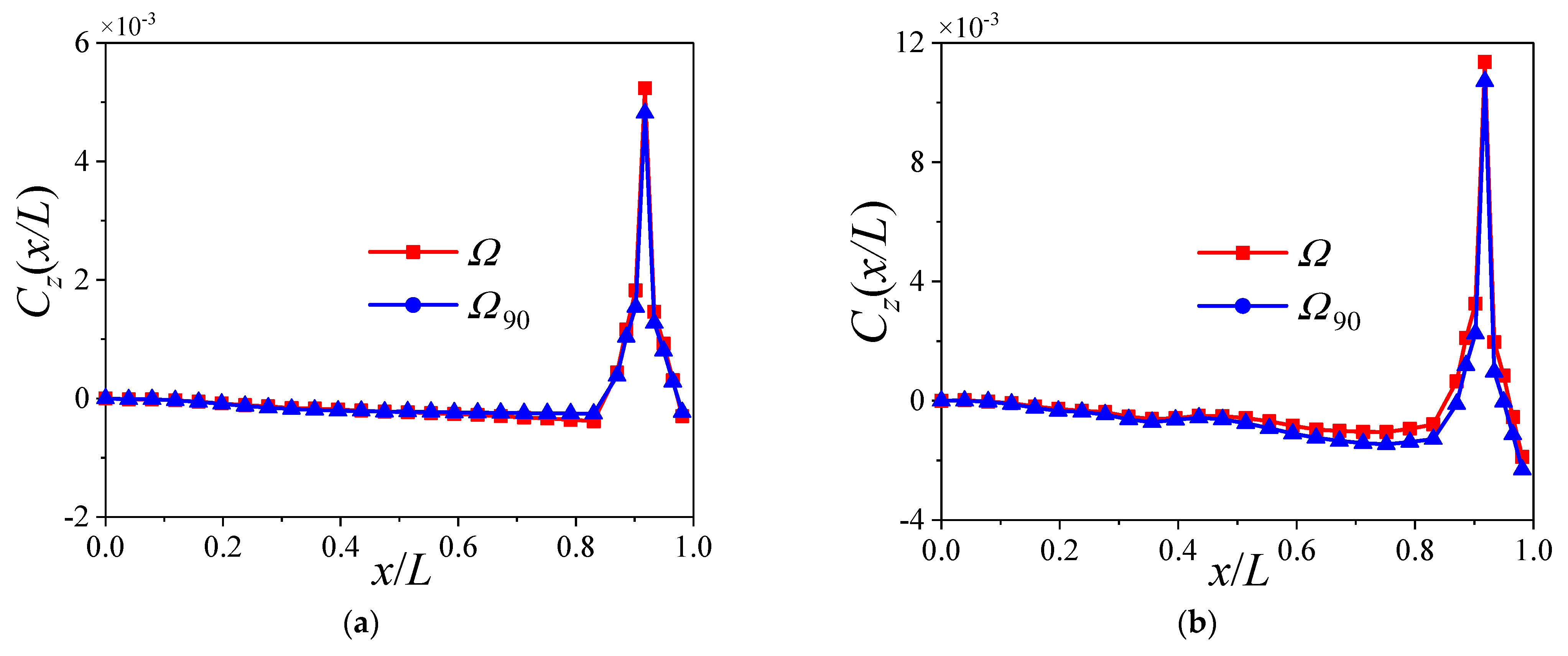
Figure 27 shows the distribution of the time−averaged lateral force coefficient C z ( x / L ) for the Ω and Ω 90 . It is seen that the variations of the C z at different α are similar when x / L 0.85 for the Ω and Ω 90 , which increase with x / L . Due to the larger value of the C z ( x / L ) of the tail at same α , the additional angle of attack greatly affects the lateral force of the tail. That causes the obvious change of the C z ( x / L ) of the tail for the Ω 90 . More specifically, its value decreases under α = 4 ° , but it increases when α = 12 ° .
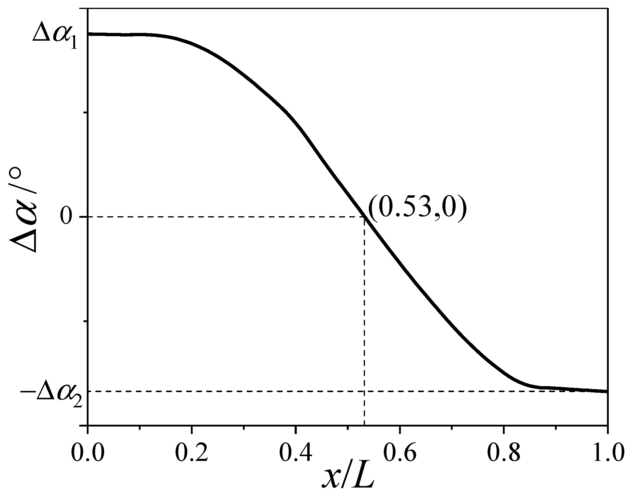
Figure 28 shows the distribution of the additional angle of attack α induced by the Ω 90 . In Figure 28, the distribution curve of the α is approximately central symmetry about the point (0.53, 0). The α decreases from α 1 to zero when x / L [ 0 ,   0.53 ] , while it decreases from zero to − α 2 for x / L ( 0.53 ,   1 ] . As mentioned above, the lateral force of the tail is more sensitive to the change of the angle of attack. Hence, the negative α within x / L ( 0.53 ,   1 ] has a greater influence on the lateral force of the projectile body. Form the variation of the lateral force with α in Figure 12, the lateral force will decrease when α = 4 ° due to the negative α , while it will increase at α = 12 ° .
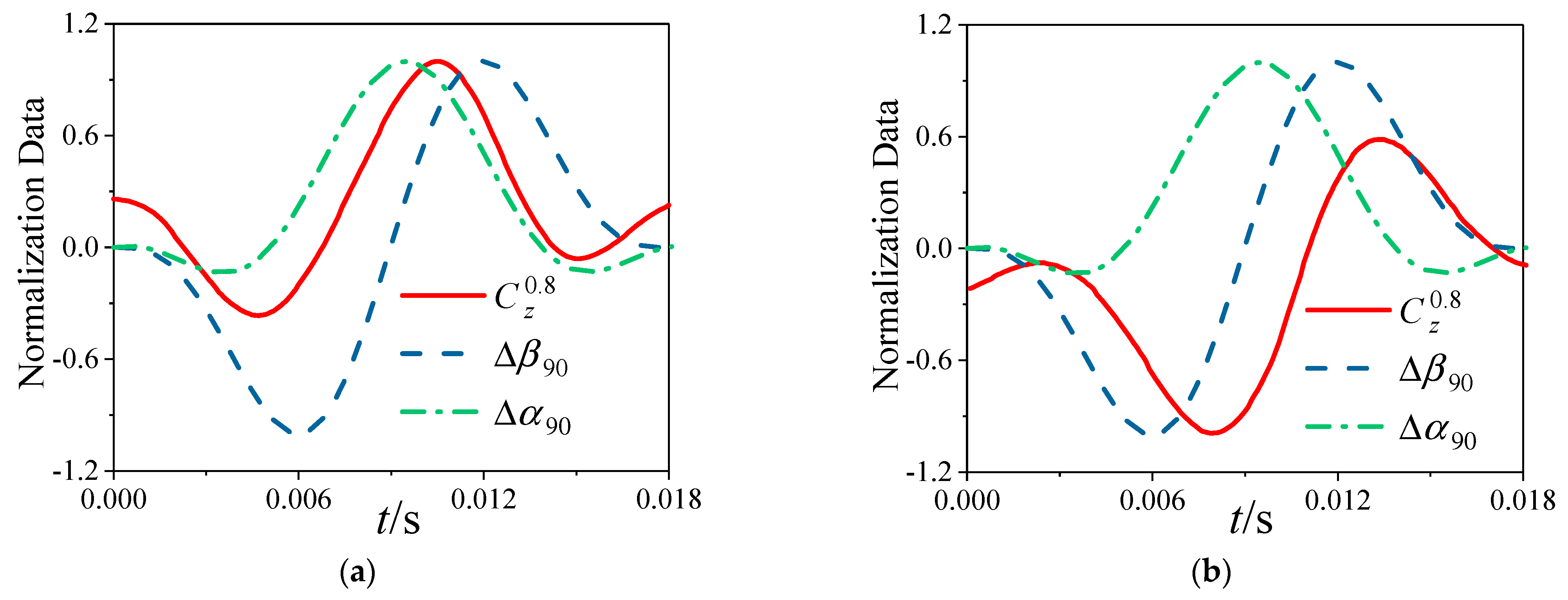
Figure 29 shows the lateral force coefficient C z 0.8 for the cross section x/L = 0.8 under different α when the trajectory is Ω 90 . The additional sideslip angle β 90 and angle of attack α 90 are also shown in Figure 29. In Figure 29a, the variation of C z 0.8 is extremely similar to that of α 90 when α = 4 ° , which indicates that the additional angle of attack is the main reason for the change of the transient lateral force of the tail at small angles of attack. As shown in Figure 29b, the variation of the C z 0.8 is similar to that of the β 90 at α = 12 ° , and there exists the characteristic of phase lag between them. This is consistent with the relationship between the lateral force of the tail and the additional attack angle or the additional sideslip angle shown in Figure 23.

8. Conclusions

The spin−deformation coupling motion model is established, and its specific trajectory is analyzed by the numerical method. On this basis, the URANS equations are solved to simulate the flow over a large−aspect−ratio projectile experiencing spin−deformation coupling motion using the unsteady numerical simulation method and the dynamic mesh technology, and the lateral force is obtained. Furtherly, the flow mechanism for the changed lateral force induced by the bending deformation is analyzed. The conclusions are drawn as follows:
  • The variation of the transient lateral force for the head of the projectile is consistent with that of the additional sideslip angle induced by the bending deformation, and it is almost independent of the angle of attack.
  • The compression wave and expansion wave will increase the time−averaged lateral force for the middle of projectile at small angles of attack, while they have little effect on its value at large angles of attack.
  • At small angles of attack, the coupling of the additional angle of attack and spinning motion is the main reason for the change of the transient lateral force for the tail of the projectile, while the additional sideslip angle will increase its time−averaged lateral force.
  • At large angles of attack, the separation vortex will lead to a phase lag between the transient lateral force for the tail of the projectile and the additional sideslip angle, which will increase the time−averaged lateral force for the tail.

Author Contributions

Conceptualization, Q.L. and J.L.; methodology, Q.L.; software, J.L.; validation, Q.L., Y.Y. and J.Y.; formal analysis, Q.L.; investigation, Q.L. and J.L.; resources, J.L. and Y.Y.; data curation, Q.L.; writing—original draft preparation, Q.L.; writing—review and editing, Q.L., J.L., Y.Y. and J.Y.; visualization, Q.L.; supervision, J.L.; project administration, J.L.; funding acquisition, J.L. All authors have read and agreed to the published version of the manuscript.

Funding

This research was funded by the National Natural Science Foundation of China, grant number 11372040.

Data Availability Statement

Not applicable.

Conflicts of Interest

The authors declare no conflict of interest.

References

  1. Huang, C.; Liu, W.; Yang, G. Numerical studies of static aeroelastic effects on grid fin aerodynamic performances. Chin. J. Aeronaut. 2017, 30, 1300–1314. [Google Scholar] [CrossRef]
  2. Liu, W.; Zhang, W.; Jiang, S.; Zhao, Z.; Zhu, H. Study of effect of elastic deformation on aerodynamic characteristics of a slender missile(rocket). J. Proj. Rocket. Missiles Guid. 2010, 30, 177–180. [Google Scholar]
  3. Yin, J.; Lei, J.; Wu, X.; Lu, T. Aerodynamic characteristics of a spinning projectile with elastic deformation. Aerosp. Sci. Technol. 2016, 51, 181–191. [Google Scholar] [CrossRef]
  4. Vaughn, H.R.; Reis, G.E. A magnus theory. AIAA J. 1973, 11, 1396–1403. [Google Scholar] [CrossRef]
  5. Jimenez−Varona, J. Numerical analysis of the Magnus effect on the forces past an axisymmetric body at high incidence. Aerospace 2023, 10, 163. [Google Scholar] [CrossRef]
  6. Sturek, W.B.; Kayser, L.D.; Nietubicz, C.J.; Reklis, R.P.; Opalka, K.O.; Dwyer, H.A. Computations of Magnus effects for a yawed, spinning body of revolution. AIAA J. 1978, 16, 687–692. [Google Scholar] [CrossRef]
  7. Cayzac, R.; Carette, E.; Denis, P.; Guillen, P. Magnus effect: Physical origins and numerical prediction. J. Appl. Mech. 2011, 78, 051005. [Google Scholar] [CrossRef]
  8. Martin, J.C. On Magnus effects caused by the boundary−layer displacement thickness on bodies of revolution at small angles of attack. J. Aeronaut. Sci. 1957, 24, 421–429. [Google Scholar] [CrossRef]
  9. Iversen, J.D. Correlation of Magnus force data for slender spinning cylinders. J. Spacecr. Rocket. 1973, 10, 268–272. [Google Scholar] [CrossRef]
  10. Morote, J.; Liaño, G. Prediction of nonlinear rolling and magnus coefficients of cruciform−finned missiles. J. Aircr. 2010, 47, 1413–1425. [Google Scholar] [CrossRef]
  11. Simon, F.; Deck, S.; Guillen, P.; Merlen, A.; Cayzac, R. Numerical simulation of magnus force control for projectiles configurations. Comput. Fluids 2009, 38, 965–968. [Google Scholar] [CrossRef]
  12. Klatt, D.; Hruschka, R.; Leopold, F. Investigation of the Magnus effect of a generic projectile at Mach 3 up to 16 degrees angle of attack. J. Appl. Mech. 2013, 80, 031603. [Google Scholar] [CrossRef]
  13. Yin, J.; Wu, X.; Lei, J. Body−fin interference on the Magnus effect of spinning projectile in supersonic flows. Eng. Appl. Comput. Fluid Mech. 2017, 11, 496–512. [Google Scholar] [CrossRef]
  14. Yin, J.; Wu, X.; Lei, J.; Lu, T.; Liu, X. Canards interference on the Magnus effect of a fin−stabilized spinning missile. Adv. Mech. Eng. 2018, 10, 1–16. [Google Scholar] [CrossRef]
  15. Cayzac, R.; Carette, E.; Heddadj, S. Complex aerodynamics behavior of high spin APFSDS projectile. J. Appl. Mech. 2013, 80, 031601. [Google Scholar] [CrossRef]
  16. Zhang, G.Q.; Yu, S.C.; Schlüter, J. Aerodynamic characteristics of a wrap−around fin rocket. Aircr. Eng. Aerosp. Technol. 2016, 88, 82–96. [Google Scholar] [CrossRef]
  17. Nygaard, T.A.; Meakin, R.L. Aerodynamic analysis of a spinning missile with dithering canards. J. Spacecr. Rocket. 2004, 41, 726–734. [Google Scholar] [CrossRef]
  18. Blades, E.L.; Marcum, D.L. Numerical simulation of a spinning missile with dithering canards using unstructured grids. J. Spacecr. Rocket. 2004, 41, 248–256. [Google Scholar] [CrossRef]
  19. Murphy, C.H.; Mermagen Sr, W.H. Spin−yaw lockin of an elastic finned projectile. J. Guid. Control Dyn. 2005, 28, 121–130. [Google Scholar] [CrossRef]
  20. Murphy, C.H.; Mermagen Sr, W.H. Flight motion of a continuously elastic finned missile. J. Guid. Control Dyn. 2003, 26, 89–98. [Google Scholar] [CrossRef]
  21. Ehramianpour, M.; Haddadpour, H.; Ahmadian, M.T. Aeroelastic behavior of a slender body considering free fittings. J. Mech. Sci. Technol. 2010, 24, 1755–1762. [Google Scholar] [CrossRef]
  22. Ericsson, L.E.; Pavish, D. Aeroelastic vehicle dynamics of a proposed delta II 7920−10L launch vehicle. J. Spacecr. Rocket. 2000, 37, 28–38. [Google Scholar] [CrossRef]
  23. Dowell, E.; Edwards, J.; Strganac, T. Nonlinear aeroelasticity. J. Aircr. 2003, 40, 857–874. [Google Scholar] [CrossRef]
  24. Wu, X.; Lu, T.; Lei, J. Effects of head deformation on aerodynamic characteristics of spinning vehicle. Proc. Inst. Mech. Eng. G J. Aerosp. Eng. 2015, 229, 1975–1986. [Google Scholar] [CrossRef]
  25. Youn, E.B.; Silton, S.I. Numerical study on bending body projectile aerodynamics. In Proceedings of the 34th AIAA Applied Aerodynamics Conference, Washington, DC, USA, 14 June 2016; p. 4331. [Google Scholar]
  26. Paul, J.; Silton, S.I. Influence of bending locations and angles on the aerodynamic performance of a bent body projectile. In Proceedings of the 2018 AIAA Aerospace Sciences Meeting, Kissimmee, FL, USA, 8 January 2018; p. 1269. [Google Scholar]
  27. Argyropoulos, C.D.; Markatos, N.C. Recent advances on the numerical modelling of turbulent flows. Appl. Math. Model. 2015, 39, 693–732. [Google Scholar] [CrossRef]
  28. Catalano, P.; Amato, M. An evaluation of RANS turbulence modelling for aerodynamic applications. Aerosp. Sci. Technol. 2003, 7, 493–509. [Google Scholar] [CrossRef]
  29. Blazek, J. Computational Fluid Dynamics: Principles and Applications; Butterworth−Heinemann: Oxford, UK, 2015. [Google Scholar]
  30. Ozcatalbas, M.; Acar, B.; Uslu, S. Effect of free−play and initial conditions on aeroelastic behavior of a missile canard in supersonic flow. In Proceedings of the AIAA AVIATION Forum, Virtual Event, 15−19 June 2020; p. 2663. [Google Scholar]
  31. De Boer, A.; Van der Schoot, M.S.; Bijl, H. Mesh deformation based on radial basis function interpolation. Comput. Struct. 2007, 85, 784–795. [Google Scholar] [CrossRef]
  32. Niu, J.; Lei, J.; He, J. Radial basis function mesh deformation based on dynamic control points. Aerosp. Sci. Technol. 2017, 64, 122–132. [Google Scholar] [CrossRef]
  33. Jameson, A. Time dependent calculations using multigrid, with applications to unsteady flows past airfoils and wings. In Proceedings of the 10th Computational Fluid Dynamics Conference, Honolulu, HI, USA, 24–26 June 1991; p. 1596. [Google Scholar]
  34. Pandya, S.A.; Venkateswaran, S.; Pulliam, T.H. Implementation of preconditioned dual−time procedures in overflow. In Proceedings of the 41st AIAA Aerospace Sciences Meeting and Exhibit, Reno, NV, USA, 23–26 June 2003; p. 72. [Google Scholar]
  35. Turkel, E.; Vatsa, V.N. Choice of variables and preconditioning for time dependent problems. In Proceedings of the 16th AIAA Computational Fluid Dynamics Conference, Orlando, FL, USA, 23–26 June 2003; p. 3692. [Google Scholar]
  36. Uselton, J.C.; Carman, J.B. A study of the Magnus effects on a sounding rocket at supersonic speeds. J. Spacecr. Rocket. 1971, 8, 28–34. [Google Scholar] [CrossRef]
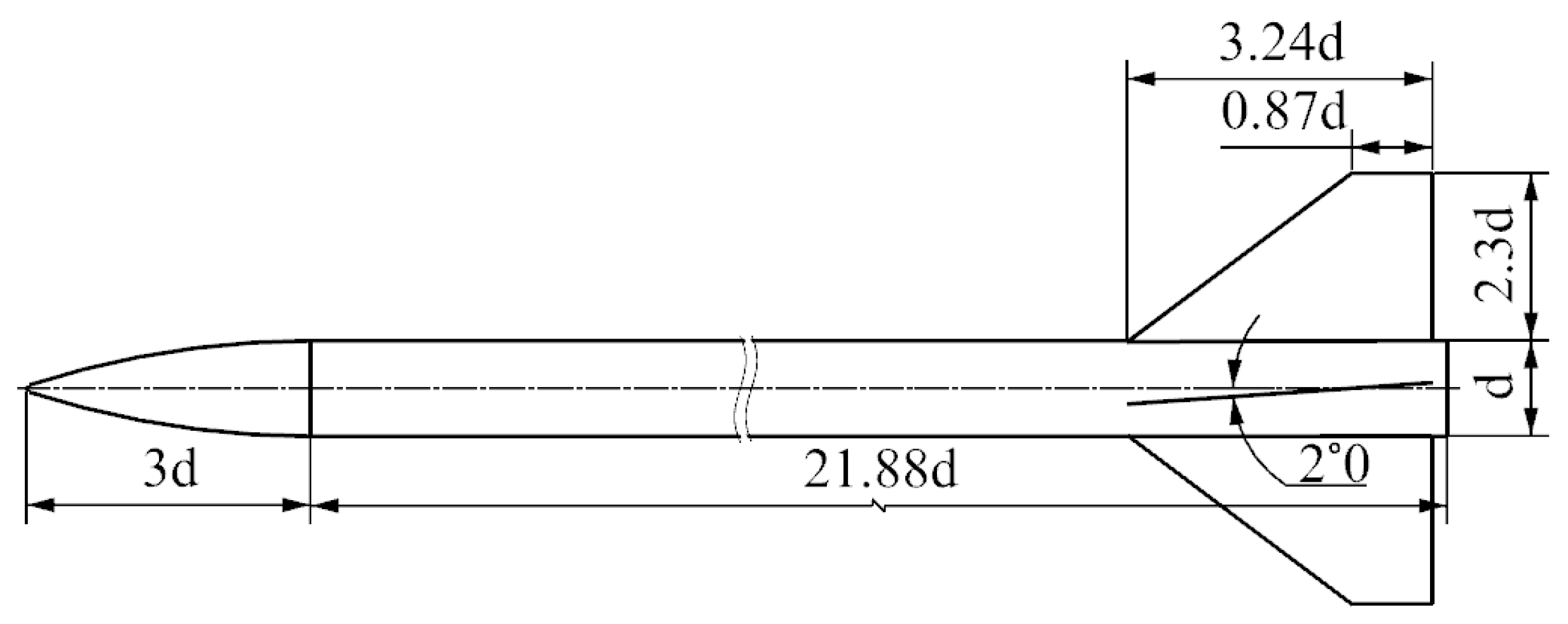
Figure 1. Model dimension of the Apache.
Aerospace 10 00810 g001
Figure 2. Definitions of spin direction, fins and roll angle.
Aerospace 10 00810 g002
Figure 3. Computational mesh.
Aerospace 10 00810 g003
Figure 4. Diagram of the spin−deformation coupling motion.
Aerospace 10 00810 g004
Figure 5. First order mode shape of the Apache.
Aerospace 10 00810 g005
Figure 6. Spin−deformation coupling motion trajectories.
Aerospace 10 00810 g006
Figure 7. Aerodynamic coefficients within a spin cycle at different time steps. (a) C n and C z ; (b) C m z and C m y .
Aerospace 10 00810 g007
Figure 8. Comparison of experimental data and CFD results. (a) C z ; (b) C m y .
Aerospace 10 00810 g008
Figure 9. Comparison of numerical results obtained in this paper and that obtained in Ref. [3].
Aerospace 10 00810 g009
Figure 10. Variation of the time−averaged lateral force coefficient for the projectile with the trajectory Ω Δ θ .
Aerospace 10 00810 g010
Figure 11. Variation of time−averaged lateral force coefficient for the projectile body with Ω Δ θ .
Aerospace 10 00810 g011
Figure 12. Variation of time−averaged lateral force coefficient for the projectile with α .
Aerospace 10 00810 g012
Figure 13. Variation of time−averaged lateral force coefficient for the projectile body with α .
Aerospace 10 00810 g013
Figure 14. Variation of time−averaged lateral force coefficient for the fins with α . (a) Ω 0 ; (b) Ω 90 .
Aerospace 10 00810 g014
Figure 15. Variation of time−averaged lateral force coefficient for the projectile with deformation amplitude A. (a) Ω 0 ; (b) Ω 90 .
Aerospace 10 00810 g015
Figure 16. Variation of time−averaged lateral force coefficient for the projectile body with deformation amplitude A. (a) Ω 0 ; (b) Ω 90 .
Aerospace 10 00810 g016
Figure 17. Characteristic moment for the trajectory (a) Ω 0 and (b) Ω 90 .
Aerospace 10 00810 g017
Figure 18. Compression wave and expansion wave induced by the deformation. V and P, respectively, represent velocity and pressure.
Aerospace 10 00810 g018
Figure 19. Effect of compression wave and expansion wave on the aerodynamic force of the fins. (a) Moment P; (b) moment Q; (c) moment R.
Aerospace 10 00810 g019
Figure 20. Diagram of the circumferential angle χ in the cross section.
Aerospace 10 00810 g020
Figure 21. Distribution of time−averaged lateral force coefficient C z ( x / L ) for the Ω and Ω 0 at different angles of attack α . (a) α = 4 ° ; (b) α = 12 ° .
Aerospace 10 00810 g021
Figure 22. Lateral force coefficient C z 0.1 and additional slip angle β 0 at the cross section x/L = 0.1 for the Ω 0 .
Aerospace 10 00810 g022
Figure 23. Lateral force coefficient C z 0.5 and lateral component δ z 0 at the cross section x/L = 0.5 for the Ω 0 .
Aerospace 10 00810 g023
Figure 24. Lateral force coefficient C z 0.8 , additional sideslip angle β 0 and angle of attack α 0 at the cross section x/L = 0.8 for the Ω 0 .
Aerospace 10 00810 g024
Figure 25. Pressure contour, streamlines and pressure difference C P + Z C P Z between the right and left sides of the cross section x/L = 0.8 at the moment S for the Ω and Ω 0 when α = 4 ° . (a) Ω ; (b) Ω 0 ; (c) pressure difference.
Aerospace 10 00810 g025
Figure 26. Pressure contour, streamlines and pressure difference C P + Z C P Z between the right and left sides of the cross section x/L = 0.8 at the moment S for the Ω and Ω 0 when α = 12 ° . (a) Ω ; (b) Ω 0 ; (c) pressure difference.
Aerospace 10 00810 g026aAerospace 10 00810 g026b
Figure 27. Distribution of time−averaged lateral force coefficient C z ( x / L ) for the Ω and Ω 90 at different angles of attack α . (a) α = 4 ° ; (b) α = 12 ° .
Aerospace 10 00810 g027
Figure 28. Distribution of additional angle of attack induced by the trajectory Ω 90 .
Aerospace 10 00810 g028
Figure 29. Lateral force coefficient C z 0.8 , additional angle of attack α 90 and sideslip angle β 90 at the cross section x/L = 0.8 for the trajectory Ω 90 . (a) α = 4 ° ; (b) α = 12 ° .
Aerospace 10 00810 g029
Table 1. Grid parameters.
ApacheCoarseFine
Axial345505
Spanwise7191
Circumferential140180
Total (Mil.)6.4712.82
Table 2. Relative difference of aerodynamic coefficients.
Apache C n C z C m z C m y
Coarse–Fine−0.08−2.62−0.167.51
Table 3. Computational conditions.
R e L Ma ω ¯ X ¯ c g α A
1.54 × 1073.00.0110.440°~12°0~0.2d
Disclaimer/Publisher’s Note: The statements, opinions and data contained in all publications are solely those of the individual author(s) and contributor(s) and not of MDPI and/or the editor(s). MDPI and/or the editor(s) disclaim responsibility for any injury to people or property resulting from any ideas, methods, instructions or products referred to in the content.