Abstract
It is well-established that the honeycomb sandwich composite structures are easily prone to damage under low-energy impact. Consequently, it would lead to a dramatic decrease in structural load-bearing capacity and a threat to overall safety. Both experimental and numerical simulations are carried out to investigate the impact damage behavior of honeycomb sandwich composite specimens. The damage mode, damage parameters, and contact force-time curves of three types of panel materials with T300, T700, and T800 are obtained under different impact energies of 10 J, 20 J, and 40 J by the drop-weight impact experiment. Moreover, digital image correlation (DIC) tests are used to measure the deformation and strain of the lower panel. The experimental results reveal that the degree of damage increases with increasing impact energy. Particularly, the T300 panel specimen exhibits visible fiber fracture when subjected to an impact energy of 40 J. The impact process involves matrix cracking, fiber fracture, and delamination of the upper panel occurring first, followed by immediate crush damage to the honeycomb core and, finally, slight fiber damage to the lower panel. Due to its higher strength, the T800 panel specimen exhibits the highest damage resistance compared to the T700 and T300 panel specimens. To consider the microscopic failure criteria and various types of contact during the impact process, a finite element model of honeycomb sandwich composites is established, and numerical simulation analysis of low-energy impact is performed to determine the damage mode, damage size, and contact-force curves. Comparative analysis demonstrates good agreement between the simulation and experimental results. The findings of this study provide valuable technical support for the widespread application of honeycomb sandwich composites in the aviation field.
1. Introduction
As a lightweight and high-strength material with exceptional specific rigidity and strength, honeycomb sandwich composites find extensive applications in the aerospace industry [1,2,3,4,5,6,7]. These applications include aircraft components such as rudders, flaps, elevators, wings/tail trailing edges, landing gear compartment doors, APU compartment doors, and radar covers, among others. Typically, a honeycomb sandwich composite consists of an upper panel, a lower panel, and a honeycomb core sandwiched between them. The adhesive film is used to bond these components together; the honeycomb sandwich composites are shown in Figure 1. The upper and lower panels primarily contribute to the overall structure’s strength and stiffness. On the other hand, the honeycomb core bears shear loads, maintains the separation between the two panels, and enhances the overall structure’s impact resistance, explosion resistance, and energy absorption capabilities [8,9].
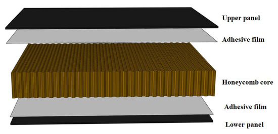
Figure 1.
Honeycomb sandwich composites.
Sandwich structures typically consist of panels made of either metal materials or composites [10,11,12]. Composite panels are commonly employed in the aerospace industry to achieve weight reduction. The core material used in sandwich structures usually includes options such as aluminum honeycomb, Nomex honeycomb, aluminum foam, and non-metallic foam [13,14,15,16]. Aramid paper-impregnated resin is often utilized for paper honeycomb cores due to its lightweight nature, non-flammability, and high specific strength. Consequently, it is the most widely employed core material in sandwich structures.
It is important to note that the panels of honeycomb sandwich composite are thin and susceptible to impacts during usage, including runway debris, hail, and tool drops. These impacts can lead to local fiber breakage, thereby reducing the overall strength and service life of the structure [17]. When subjected to higher impact energy, the panel may experience penetration, exposing the core. The damping properties of the core can influence the adhesive strength, potentially resulting in large-scale failure between the panel and the core, leading to significant damage. Numerous failure accidents of sandwich structures have been attributed to impact damage.
Researchers have conducted a series of studies on the damage behavior of honeycomb sandwich composites under impact energy. The research on damage to sandwich composite materials primarily relies on experiment and simulation analysis. Baran and Weijermars [9] investigated the residual bending behavior of sandwich panels after impact, using bending tests to obtain shear cracks with progressive failure. Kolopp [18] conducted medium-velocity impact experiments on sandwich structures to enhance armor solutions for aeronautical applications. The research revealed that the combination of aluminum honeycomb core and aluminum skins yielded mitigated results. Lv [12] explored the low-velocity impact response of composite sandwich structures with grid-honeycomb hybrid cores through experimental and numerical simulation. The study demonstrated that the sandwich panels exhibited varying degrees of impact resistance at different locations. Zhang et al. [19] examined the damage response of sandwich panels with Nomex honeycomb cores under low-velocity impact conditions. They employed experiment and numerical simulation to establish a failure model based on the Hashin failure criterion and obtained insights into the intralaminar damage behavior of the laminate. The simulation results, including contact force histories, damage shapes, and indentation depths, were found to agree well with the experimental findings. Chen et al. [20] developed a numerical model to investigate intra-laminar damage, inter-laminar adhesive delamination, and the strain rate effect of sandwich structures subjected to low-velocity impact. The numerical model successfully described the essential perforation mechanisms associated with damage patterns and exhibited accurate predictions of total energy absorption, among others. Zhang et al. [21] and Sun et al. [22] separately formulated simulation and theoretical models that could better predict the damage dent response. Feng et al. [23] proposed a progressive damage model based on continuum damage mechanics. They introduced cohesive interface elements to predict interlaminar damage and failure mechanisms in composites.
The low-energy impact damage experiment and finite element simulation analysis are conducted on honeycomb sandwich composites in this paper. The study aims to determine the damage mode and assess the damage resistance of these structures. The research findings will serve as valuable technical support for the widespread application of honeycomb sandwich structures in the aviation industry.
2. Experiments
2.1. Specimen
Figure 2 illustrates the specimen of the honeycomb sandwich composite structure. The specimen consists of an upper panel, a lower panel, and a paper honeycomb core positioned in between. The panels and honeycomb core are bonded together using a high-strength adhesive film. The dimensions of the specimen are depicted in Figure 3. The length of the specimen measures 150 mm, the width is 100 mm, and the height of the honeycomb core is 19.5 mm.
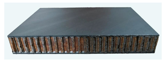
Figure 2.
Honeycomb sandwich composite specimen.
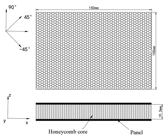
Figure 3.
The size of the specimen.
The upper and lower panels of the honeycomb sandwich composite structure are made of fiber-reinforced unidirectional strips. The strips are arranged in a [45/0/90/-45]s stacking sequence. In this study, three types of materials are chosen for the panels: T300, T700, and T800. Table 1 provides information about the specimen, while Table 2 presents the data on the unidirectional strip material. As for the honeycomb core, it is composed of a regular hexagonal paper honeycomb. The typical sizes of the honeycomb cells are W = 1.8 mm and D = 3.2 mm, with a single layer wall thickness of 0.05 mm. Figure 4 illustrates the honeycomb core structure.

Table 1.
The information of specimen.
Table 2.
The data of the unidirectional strip.
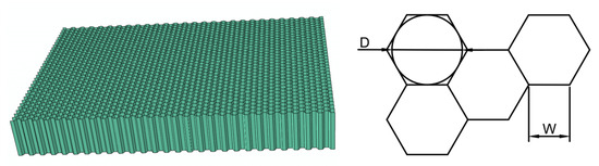
Figure 4.
The honeycomb core.
2.2. Experimental Device Description
In accordance with the ASTM D3763 standard for impact experiments, the impact tests on the honeycomb sandwich composite specimens are conducted using the Instron CEAST 9350 drop hammer impact testing machine, as depicted in Figure 5. The drop hammer used in the experiment has a spherical shape, a mass of 5.52 kg, and a diameter of 20 mm. During the experiment, the impact energies are varied by adjusting the height of the drop hammer punch. The honeycomb sandwich composite specimens are securely fixed in a fixture, which is installed on the bedstand of the testing machine. The installation method can be seen in Figure 6.
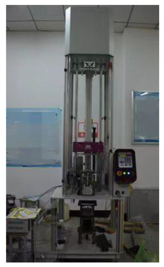
Figure 5.
Drop hammer impact testing machine.
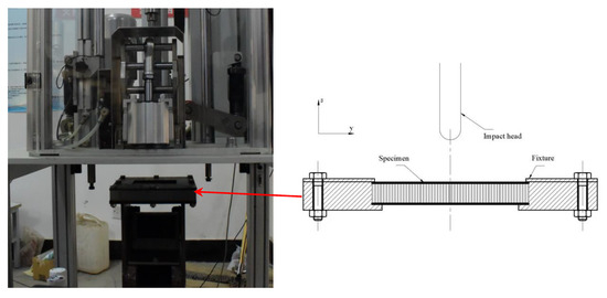
Figure 6.
Installation method of specimen.
2.3. Impact Experiment
The low-energy impact experiment on the honeycomb sandwich composite specimen is performed with impact energies of 10 J, 20 J, and 40 J, as indicated in Table 3. Various parameters and data are recorded during the experiment, including the damage mode, damage sizes, and the contact force-time curves for the punch. Additionally, the displacement and strain measurements are obtained using a digital image correlation (DIC) test system specifically for lower panels; the type of camera for the DIC is ix_speed, with a sampling frequency of 10~50 wHz. This system allows for accurate recording and analysis of the panel’s deformation and strain behavior during the impact process.
Table 3.
The relationship between impact energy and specimens.
3. Experimental Results and Discussion
3.1. Damage Modes and Discussion
Based on the low-energy impact experiment, the impact damage of the honeycomb sandwich composite specimens at different energies is obtained and is presented in Figure 7, Figure 8 and Figure 9. These figures illustrate the visible impact damage on the specimens, the figures on the right side of Figure 7c to Figure 9c show an enlarged view of the damage under different energies. Furthermore, Figure 10 displays the damage profile of the T700 panel specimen after being cut from the middle. This provides a detailed view of the internal damage caused by the impact. To analyze the displacement behavior of the T700 lower panel during an impact with an energy of 40 J, Figure 11 shows the displacement contour obtained using the DIC test system. This contour map demonstrates the magnitude and distribution of displacements on the panel’s surface. For a comparison of impact damage on the upper panels, Figure 12 shows the damage profiles, while Table 4 presents a summarized evaluation of the damage data for each panel specimen; the damage data is measured by a micrometer.
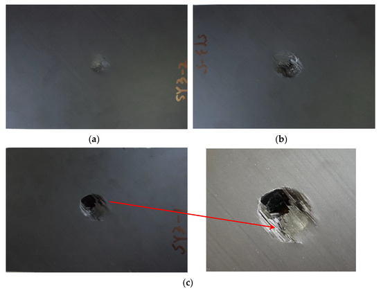
Figure 7.
Impact damage for the T300 panel specimens: (a) 10 J; (b) 20 J; (c) 40 J.
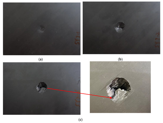
Figure 8.
Impact damage for the T700 panel specimens: (a) 10 J; (b) 20 J; (c) 40 J.
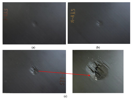
Figure 9.
Impact damage for the T800 panel specimens: (a) 10 J; (b) 20 J; (c) 40 J.
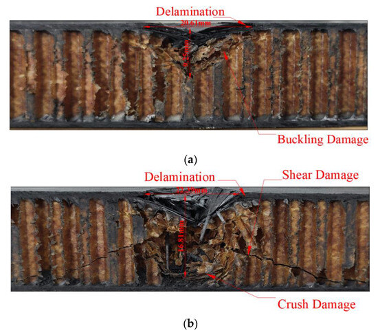
Figure 10.
Damage of the T700 panel specimens: (a) 20 J; (b) 40 J.
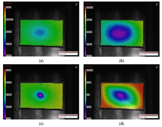
Figure 11.
Displacement contour of the T700 lower panel under impact energy of 40 J: (a) t = 2 ms; (b) t = 5 ms; (c) t = 9 ms; (d) t = 12 ms.
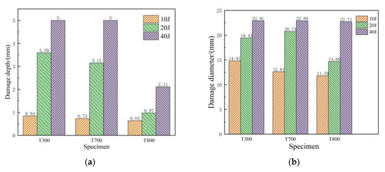
Figure 12.
Damage comparison of upper panel: (a) damage depth; (b) damage width.
Table 4.
Damage data comparison of the upper panel.
After analyzing the experimental results, damage modes and data of the specimens are obtained. By comparing Figure 7 to Figure 12 and Table 4, the following conclusions can be drawn:
- (1)
- Under low-energy impact, the upper panel exhibits the most severe damage, including fiber fracture, matrix cracking, and delamination. The honeycomb core in the middle experiences compressive feedback damage, while the damage to the lower panel is relatively slight.
- (2)
- In the case of the T300 honeycomb sandwich composite specimen, subjected to an impact energy of 10 J, the main damages in the impact area of the upper panel are fiber fracture and delamination, with a small region of the honeycomb core experiencing slight crushing damage. Overall, the specimen shows minimal damage, characterized by a small damage depth and width. Under an impact energy of 20 J, the fiber fracture area in the upper panel increases, along with severe delamination. The damage width, damage depth, and damage area all increased significantly compared to the impact energy of 10 J. When impacted with energy of 40 J, the upper panel is completely penetrated, resulting in extensive crushing damage and buckling of the honeycomb core. Damage to the lower panel is visibly noticeable, with the main damage being fiber breakage. However, the damage degree is relatively small, demonstrating the energy absorption capability of the honeycomb core.
- (3)
- In the case of the T700 honeycomb sandwich composite specimen, under an impact energy of 10 J, the damage to the upper panel is relatively slight, mainly consisting of a small amount of fiber fracture and delamination, with smaller damage width and damage depth. When subjected to the impact energy of 20 J, the areas of fiber fracture in the upper panel increase, along with an increase in damage width and dent depth. Under the impact energy of 40 J, the upper panel is penetrated, while the lower panel exhibits only a small amount of deformation as measured by DIC testing, which is not visually apparent.
- (4)
- As for the honeycomb sandwich composite specimen of the T800 panel, there is a slight indentation on the upper panel under the impact energy of 10 J, but the damage is not as pronounced compared to the T300 and T700 panels. Under the impact energy of 20 J, the damage area in the upper panel increases, but overall damage remains relatively small. Under the impact energy of 40 J, the damage width, damage area, and dent depth increase significantly. The honeycomb core in the middle collapses, while the lower panel exhibits a slight amount of deformation as measured by DIC testing, which is not visually apparent.
- (5)
- By comparing Table 4 and Figure 12, it can be observed that as the impact energy increases, the damage width, dent depth, and other damage data increase for the same type of specimens. Under the same impact energy, different panel materials exhibit different resistance to impact damage. The T300 panel specimen suffers the largest damage area, damage width, and dent depth, indicating the most severe impact damage. The T700 panel ranks second in terms of damage severity, while the T800 panel specimen experiences the smallest amount of damage thanks to its superior strength performance and ability to resist impact damage (as shown in Table 2).
3.2. Impact Response
The contact force-time curves of the punch during the experiment are depicted in Figure 13. These curves can be divided into three stages: the rising stage, the fluctuating stage, and the falling stage. When the punch contacts the upper panel initially, the contact force increases rapidly in a short period of time, reaching the first peak. Subsequently, the contact force decreases and fluctuates within a small range before reaching the second peak, which represents the maximum value of the entire contact force-time curve. Finally, the contact force gradually decreases over time until it reaches zero.
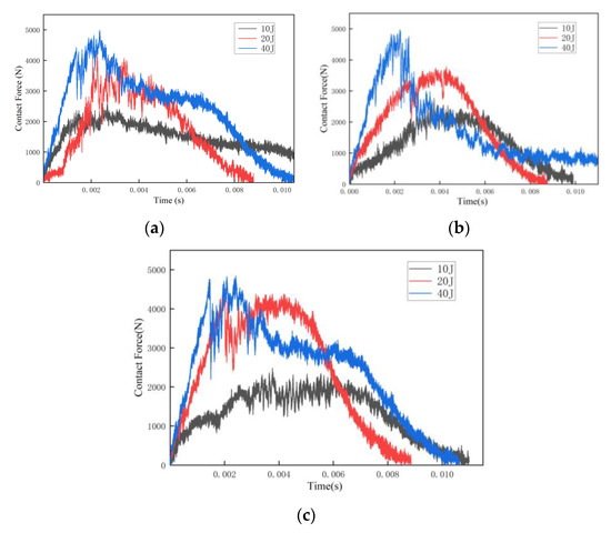
Figure 13.
The curves of contact force-time: (a) T300 panels; (b) T700 panels; (c) T800 panels.
Table 5 presents the peak impact forces for the honeycomb sandwich composite specimen under impact energies of 10 J, 20 J, and 40 J. Through comparative analysis; the following conclusions can be drawn:
Table 5.
The comparison of the contact force peak.
- (1)
- Under the same impact energy, the panel’s material has little influence on the peak contact force, with a difference of about 4%.
- (2)
- Under the same impact energy, the duration time during the impact process is basically the same for the different panel materials, and the arrival time of the peak contact force is also the same.
- (3)
- With the increase in impact energy, the peak contact force increases, but the rate of increase in the peak impact force is smaller than the rate of energy’s increase. The increase in impact energy causes the contact force peak to arrive earlier.
- (4)
- Variations in rebound are observed among panels composed of different materials when subjected to diverse levels of impact energy, leading to discrepancies in the ultimate contact duration.
4. Numerical Simulation
4.1. Finite Element Model
A finite element model of a honeycomb sandwich composite specimen is created by using the finite element software ABAQUS. The modal consists of four components: the upper panel, lower panel, honeycomb core, and drop hammer. The simulation focuses on a T700 panel specimen, where the dimensions, panel material, and laying methods in the finite element model are consistent with the experimental specimen of the T700 panel.
For the paper honeycomb core, specific features are taken into consideration. The modeling incorporates W = 1.8 mm and D = 3.2 mm dimensions, as depicted in Figure 4; the material parameters of honeycomb core used in the calculation is taken from references [24], E1 = 2.5 GPa, E2 = E3= 1.3 GPa, = 0.2, = 0.3, = 0.72 g/cm3. The adhesive relationship between the double-layer aramid paper is neglected, and the honeycomb structure is simplified to a single layer with a wall thickness of 0.05 mm. The drop hammer is represented as an analytical rigid body with a diameter of 20 mm. An inertial mass point measuring 5.52 kg is added at the center of the drop hammer punch. The impact energy is adjusted by manipulating the impact velocity.
The finite element model, illustrated in Figure 14 (Different colors in the model represent different materials), employs 8-node linear reduced integral elements (C3D8R) for the upper and lower panels. To prevent significant mesh distortion and calculation termination, hourglass control is implemented. The laying method for the upper and lower panels follows the sequence [45/0/90/-45]s, as shown in Figure 15 (Different colors represent different fiber laying methods). The material parameters of the panel are taken from Table 2. Considering the relatively small wall thickness of the honeycomb core compared to the core cell size, the S4R element is adopted for the Nomex honeycomb core. During the impact process, the deformation caused by the drop hammer itself is not considered, and the drop hammer is defined as an undeformed analytical, rigid body.
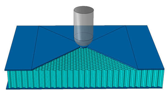
Figure 14.
Finite element model of honeycomb sandwich composites.
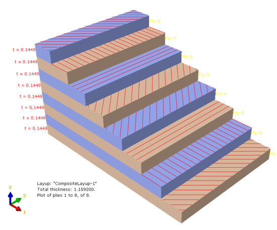
Figure 15.
The laying method of the panel.
In the finite element model, the damage failure criterion is incorporated by defining the material properties. For the in-plane damage model of the panel, a progressive damage evolution approach is adopted. The Hashin damage failure criterion is utilized to determine the initial damage of the panel elements. This criterion encompasses four types of failure modes: fiber tensile damage, fiber compressive damage, matrix tensile damage, and matrix compressive damage. The initial criterion serves as the starting point for material damage, and the simulation also considers damage evolution.
All contact conditions during the entire impact process are taken into account in the finite element simulation analysis. This includes the contact between the outer surface of the drop hammer and the upper panel, the contact between the outer surface of the drop hammer and the paper honeycomb core, the self-contact between the paper honeycomb core resulting from compression during the impact process, and the contact between the paper honeycomb core and the upper and lower panels. A penalty function is employed for tangential contact, while “hard” contact is used for normal contact. The friction coefficient is set to 0.1.
To replicate the experimental conditions, the motion of the six degrees of freedom for the four edge regions of the upper and lower panels is constrained in the model. The constraint mode is illustrated in Figure 16. The drop hammer is restricted to only moving downward in the vertical panel direction and is prevented from moving in any other direction.
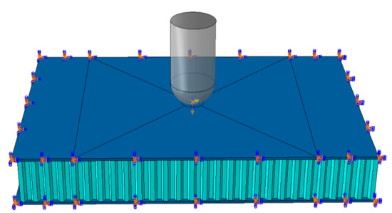
Figure 16.
Boundary constraints.
The impact load is applied to the panel through a drop hammer punch with a mass of 5.52 kg. The impact energy is adjusted by varying the velocity of the punch. In the simulation analysis, three different impact energies are considered: 10 J, 20 J, and 40 J.
4.2. Simulation Results and Discussion
The impact simulation analysis of honeycomb sandwich composite structures is performed using the finite element software ABAQUS, and the damage modes, damage sizes, and curves of contact force-time are obtained.
4.2.1. Damage Simulation Results of the Upper Panel
The finite element simulation analysis reveals that the upper panel experiences the most severe damage, including fiber fracture, matrix cracking, etc. Specifically, for the impact energy of 20 J, the damage to the top layer of the upper panel is depicted in Figure 17, the color in the figures represent the degree of damage, while the red color represents the most severe damage. The shape of fiber damage in each layer of the upper panel appears as peanut shells, perpendicular to the direction of unidirectional fiber placement.
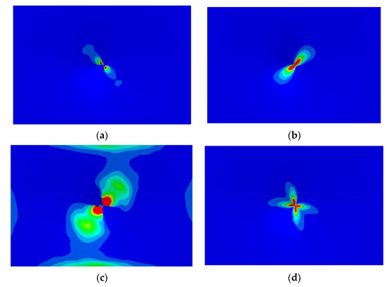
Figure 17.
Upper panel’s damage under impact energy of 20 J: (a) fiber tensile damage; (b) fiber compressive damage; (c) matrix tensile damage; (d) matrix compressive damage.
The overall damage is determined by accumulating the damage from each layer; the damage accumulation under the impact energy of 10 J is shown in Figure 18. A comparison of the damage width between the numerical simulation results and experimental results is presented in Table 6. The analysis demonstrated that the error between the simulation results and experimental results regarding the damage width is less than 6.1%. This indicates that the simulation results are in good agreement with the experimental findings, further validating their accuracy and reliability.
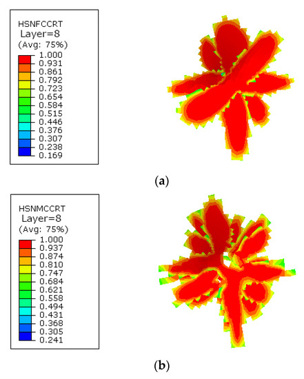
Figure 18.
Damage accumulation under the impact energy of 10 J: (a) fiber compressive damage; (b) matrix compressive damage.
Table 6.
Comparison of damage width.
To examine the internal damage behavior of the honeycomb sandwich composites, the structures are cut along the centerline of the short side. The comparison of cross-sectional damage conditions between the simulation results and experimental results is shown in Figure 19, the color represents the degree of damage, while red color represents the most severe damage. Under an impact energy of 20 J, the fibers in the upper panel near the impact area are fractured, while the adhesive film between the upper panel and the honeycomb core remains intact. As the drop hammer punch presses down on the honeycomb core, significant compressive deformation occurs. When the impact energy increases to 40 J, the upper panel experiences overall penetration, displaying a petal-shaped failure pattern. Additionally, the honeycomb core exhibits more severe deformation, characterized by large-scale crushing failure and adhesive failure in the impact area.
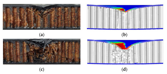
Figure 19.
Damage comparison for the honeycomb core: (a) experimental results under 20 J; (b) simulation results under 20 J; (c) experimental results under 40 J; (d) simulation results under 40 J.
4.2.2. Damage Simulation Results of Honeycomb Core
The main damage observed in the honeycomb core includes collapse in the impact center area, as well as fracture, shear failure, and buckling. The damage area extends from the impact center position towards both sides, with the largest depth of honeycomb damage occurring in the center area, forming an arc-shaped pattern extending to both sides; the displacement contour is shown in Figure 20. The comparison of the damage between the simulation results and experimental results is illustrated in Figure 19. It can be observed that the simulation results are in good agreement with the experimental findings, confirming the effectiveness and rationality of the finite element simulation model. Utilizing this model, the size and mode of damage in the honeycomb core can be accurately predicted. The damage evolution for the specimen is depicted in Figure 21.
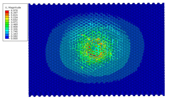
Figure 20.
Displacement contour of the honeycomb core.
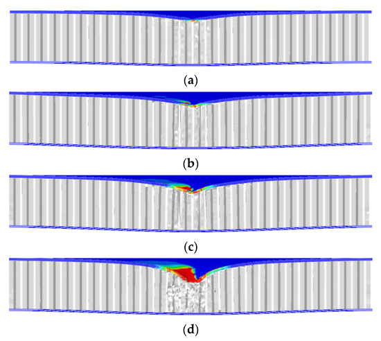
Figure 21.
Damage evolution process of the honeycomb core: (a) 5 J; (b) 10 J; (c) 20 J; (d) 40 J.
4.2.3. Damage Simulation Results of the Lower Panel
The displacement contour of the lower panel during the impact process is obtained by conducting a finite element simulation. With the impact energy of 40 J, the lower panel experiences the impact loads, including those transferred from the upper panel and honeycomb core, as well as the load from the drop hammer punch. Simulation analysis reveals that the displacement of the lower panel occurs at the corresponding position of the impact center. The displacement then diffuses along the impact center in an elliptical form towards the edge of the panel. The comparison of the displacement contour between the simulation results and DIC (Digital Image Correlation) testing results is presented in Figure 22 and Figure 23. The error between the two sets of results is controlled within 3%. This indicates that the simulation results exhibit good agreement with the DIC testing results.
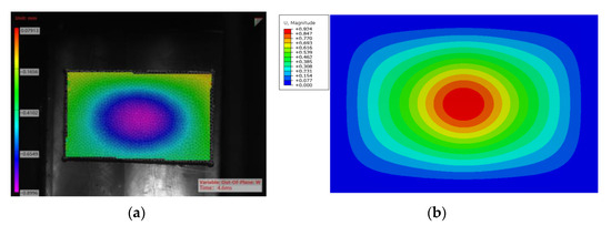
Figure 22.
Displacement comparison when drop hammer punch contacts the lower panel (40 J): (a) DIC testing results; (b) simulation results.
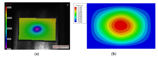
Figure 23.
Displacement comparison when the impact force of the lower panel reaches a maximum (40 J): (a) DIC testing results; (b) simulation results.
4.2.4. Curves of Contact Force-Time
The curves of contact force-time of drop hammer punch between simulation and experiment are shown in Figure 24, which shows that the simulation results have good agreement with the experimental results.
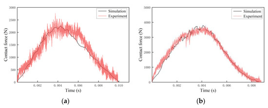
Figure 24.
Curves of contact force-time: (a) impact energy of 10 J.; (b) impact energy of 20 J.
4.3. Summary
- (1)
- In order to study the damage behavior of the honeycomb sandwich composite structure with a T700 panel, a comprehensive finite element model is established. This model takes into account factors such as the microscopic failure criteria of the panel, various contact conditions during the impact process, and the simplification of the drop hammer punch. By considering these aspects, the model aims to accurately represent the behavior of the composite structure during impact.
- (2)
- Through the finite element simulation analysis, the damage modes, damage parameters, and contact force-time curves of the honeycomb sandwich composites under different impact energies are obtained. These results provide valuable insights into the response and failure mechanisms of the composite structure under impact loading.
- (3)
- A comparison between the simulation results and experimental results demonstrates good consistency between the two. This agreement between the simulation and experimental findings confirms the correctness and validity of the finite element model employed in the study.
5. Conclusions
This study focuses on the impact damage behavior of paper honeycomb sandwich composite specimens through experiments and finite element simulations. Various factors influencing the damage, such as panel material and impact energy, are considered. The following conclusions are drawn:
- (1)
- Low-energy impact experiments are conducted on honeycomb sandwich composite specimens to determine the damage modes and damage parameters. During the impact process, the upper panel exhibits severe damage, including matrix cracking, fiber breakage, and delamination. The honeycomb core experiences compressive feedback damage, while the lower panel shows relatively minor damage, indicating the energy absorption capabilities of the honeycomb core.
- (2)
- The impact resistance of panels made from T300, T700, or T800 laminates increases with the strength of the laminate. Among them, the T800 panel demonstrates the highest resistance to impact.
- (3)
- Increasing the impact energy results in an increase in peak contact force. However, the rate of increase in peak impact force is smaller than the rate of energy increase. The panel material has minimal influence on the peak contact force, while the impact energy affects the impact time history.
- (4)
- Through finite element simulation analysis of honeycomb sandwich composites, the damage modes and damage sizes for the panels and honeycomb core are obtained, and the contact force-time curves of the punch are obtained. Comparative analysis demonstrates good consistency between the simulation and experimental results, confirming the rationality and accuracy of the finite element model.
The research findings can be applied to aircraft structural design, providing technical guidance for the lightweight and high-reliability design of aircraft. These research findings can also provide valuable technical support for the widespread application of honeycomb sandwich composite materials in the field of aviation. The results not only have important engineering application value but also have obvious challenges and innovations.
Author Contributions
Conceptualization, X.Z. and B.H.; methodology, X.Z.; software, B.H.; validation, X.Z.; formal analysis, Y.Z. and B.H.; investigation, Q.Y.; resources, X.Z.; data curation, Q.Y. and Y.C.; writing—original draft preparation, X.Z.; writing—review and editing, X.Z. and B.H.; visualization, Y.Z.; supervision, Y.H. and Z.L.; project administration, X.Z. and B.H.; funding acquisition, X.Z. All authors have read and agreed to the published version of the manuscript.
Funding
This research was funded by the Fundamental Research Program of Shanxi Province (202203021222129).
Institutional Review Board Statement
Not applicable.
Informed Consent Statement
Not applicable.
Data Availability Statement
Not applicable.
Conflicts of Interest
The authors declare no conflict of interest.
References
- Xiong, J.; Zhang, M.; Stocchi, A.; Hu, H.; Ma, L.; Wu, L.; Zhang, Z. Mechanical behaviors of carbon fiber composite sandwich columns with three dimensional honeycomb cores under in-plane compression. Compos. Part B Eng. 2014, 60, 350–358. [Google Scholar] [CrossRef]
- Foo, C.C.; Chai, G.B.; Seah, L.K. A model to predict low-velocity impact response and damage in sandwich composites. Compos. Sci. Technol. 2008, 68, 1348–1356. [Google Scholar] [CrossRef]
- Song, Z.H.; Luong, S.; Whisler, D.; Kim, H. Honeycomb core failure mechanism of CFRP/ Nomex sandwich panel under multi-angle impact of hail ice. Int. J. Impact Eng. 2021, 150, 103817. [Google Scholar] [CrossRef]
- Park, Y.B.; Kweon, J.H.; Choi, J.H. Failure characteristics of carbon/BMI-Nomex sandwich joints in various hygrothermal conditions. Compos. Part B Eng. 2014, 60, 213–221. [Google Scholar] [CrossRef]
- Wang, B.; Wu, L.Z.; Ma, L.; Feng, J.-C. Low-velocity impact characteristics and residual tensile strength of carbon fiber composite lattice core sandwich structures. Compos. Part B Eng. 2011, 42, 891–897. [Google Scholar] [CrossRef]
- Giglio, M.; Gilioli, A.; Manes, A. Numerical investigation of a three point bending test on sandwich panels with aluminum skins and Nomex™ honeycomb core. Comput. Mater. Sci. 2012, 56, 69–78. [Google Scholar] [CrossRef]
- Pydah, A.; Batra, R.C. Blast loading of bumper shielded hybrid two-core Miura-ori/honeycomb core sandwich plates. Thin-Walled Struct. 2018, 129, 45–57. [Google Scholar] [CrossRef]
- He, W.T.; Liu, J.X.; Wang, S.Q.; Xie, D. Low-velocity impact response and post-impact flexural behaviour of composite sandwich structures with corrugated cores. Compos. Struct. 2018, 189, 37–53. [Google Scholar] [CrossRef]
- Baran, I.; Weijermars, W. Residual bending behaviour of sandwich composites after impact. J. Sandw. Struct. Mater. 2018, 22, 402–422. [Google Scholar] [CrossRef]
- Huo, X.; Liu, H.; Luo, Q.; Sun, G.; Li, Q. On low-velocity impact response of foam-core sandwich panels. Int. J. Mech. Sci. 2020, 181, 105681. [Google Scholar] [CrossRef]
- Zhu, Y.; Sun, Y. Low-velocity impact response of multilayer foam core sandwich panels with composite face sheets. Int. J. Mech. Sci. 2021, 209, 106704. [Google Scholar] [CrossRef]
- Lv, H.Y.; Shi, S.S.; Chen, B.Z.; Ma, J.; Sun, Z. Low-velocity impact response of composite sandwich structure with grid–honeycomb hybrid core. Int. J. Mech. Sci. 2023, 246, 108149. [Google Scholar] [CrossRef]
- Zhang, J.; Zhou, R.; Wang, M.; Ye, Y.; Wang, T. Dynamic response of double-layer rectangular sandwich plates with metal foam cores subjected to blast loading. Int. J. Impact Eng. 2018, 122, 265–275. [Google Scholar] [CrossRef]
- Zhang, J.; Ye, Y.; Qin, Q.; Wang, T. Low-velocity impact of sandwich beams with fibre-metal laminate face-sheets. Compos. Sci. Technol. 2018, 168, 152–159. [Google Scholar] [CrossRef]
- Song, S.; Xiong, C.; Zheng, J.; Yin, J.; Zou, Y.; Zhu, X. Compression, bending, energy absorption properties, and failure modes of composite Kagome honeycomb sandwich structure reinforced by PMI foams. Compos. Struct. 2021, 277, 114611. [Google Scholar] [CrossRef]
- Mei, J.; Liu, J.; Zhang, M.; Huang, W. Experimental and numerical study on the ballistic impact resistance of the CFRP sandwich panel with the X-frame cores. Int. J. Mech. Sci. 2022, 232, 107649. [Google Scholar] [CrossRef]
- Schubel, P.M.; Luo, J.J.; Daniel, I.M. Low velocity impact behavior of composite sandwich panels. Compos. Part A 2005, 36, 1389–1396. [Google Scholar] [CrossRef]
- Kolopp, A.; Rivallant, S.; Bouvet, C. Experimental study of sandwich structures as armour against medium-velocity impacts. Int. J. Impact Eng. 2013, 61, 24–35. [Google Scholar] [CrossRef]
- Zhang, T.T.; Yan, Y.; Li, J.F. Experiments and numerical simulations of low-velocity impact of sandwich composite panels. Polym. Compos. 2017, 38, 646–656. [Google Scholar] [CrossRef]
- Chen, Y.; Hou, S.J.; Fu, K.K.; Han, X.; Ye, L. Low-velocity impact response of composite sandwich structures: Modelling and experiment. Compos. Struct. 2017, 168, 322–334. [Google Scholar] [CrossRef]
- Zhang, D.H.; Fei, Q.G.; Zhang, P.W. Drop-weight impact behavior of honeycomb sandwich panels under a spherical impactor. Compos. Struct. 2017, 168, 633–645. [Google Scholar] [CrossRef]
- Sun, M.; Wowk, D.; Mechefske, C.; Kim, I.Y. An analytical study of the plasticity of sandwich honeycomb panels subjected to low-velocity impact. Compos. Part B Eng. 2019, 168, 121–128. [Google Scholar] [CrossRef]
- Feng, D.; Aymerich, F. Finite element modelling of damage induced by low-velocity impact on composite laminates. Compos. Struct. 2014, 108, 161. [Google Scholar] [CrossRef]
- Xie, S.C.; Jing, K.K.; Zhou, H.; Liu, X. Mechanical properties of Nomex honeycomb sandwich panels under dynamic impact. Compos. Struct. 2020, 235, 111814. [Google Scholar] [CrossRef]
Disclaimer/Publisher’s Note: The statements, opinions and data contained in all publications are solely those of the individual author(s) and contributor(s) and not of MDPI and/or the editor(s). MDPI and/or the editor(s) disclaim responsibility for any injury to people or property resulting from any ideas, methods, instructions or products referred to in the content. |
© 2023 by the authors. Licensee MDPI, Basel, Switzerland. This article is an open access article distributed under the terms and conditions of the Creative Commons Attribution (CC BY) license (https://creativecommons.org/licenses/by/4.0/).