Article

Aerodynamic Characteristics of a Z-Shaped Folding Wing

Beijing Key Laboratory of Nonlinear Vibrations and Strength of Mechanical Structures, Beijing University of Technology, Beijing 100124, China
*
Author to whom correspondence should be addressed.
Aerospace 2023, 10(9), 749; https://doi.org/10.3390/aerospace10090749
Submission received: 30 June 2023 / Revised: 9 August 2023 / Accepted: 18 August 2023 / Published: 24 August 2023
(This article belongs to the Special Issue Aerodynamics Design)

Abstract

:
Z-shaped folding wings have the potential to enhance the flight performance of an aircraft, contingent upon its mission requirements. However, the current scope of research on unmanned aerial vehicles (UAVs) with Z-shaped folding wings primarily focuses on the analysis of their folding structure and aeroelasticity-related vibrations. Computational fluid dynamics methods and dynamic meshing are employed to examine the folding process of Z-shaped folding wings. By comparing the steady aerodynamic characteristics of Z-shaped folding wings with those of conventional wings, this investigation explores the dynamic aerodynamic properties of Z-shaped folding wings at varying upward folding speeds. The numerical findings reveal that the folding of Z-shaped folding wings reduces the lift-to-drag ratio, yet simultaneously diminishes the nose-down pitching moment, thereby augmenting maneuverability. Concerning unsteady aerodynamics, the transient lift and drag coefficients of the folded wing initially increase and subsequently decrease as the folding angle increases at small angles of attack. Likewise, the nose-down pitching moment exhibits the same pattern in response to the folding angle. Additionally, the aerodynamic coefficients experience a slight decrease during the initial half of the folding process with increasing folding speed. Once the wing reaches approximately 40°~45° of folding, there is an abrupt change in the transient aerodynamic coefficients. Notably, this abrupt change is delayed with higher folding speeds, eventually converging to similar values across different folding speeds.

1. Introduction

In recent years, there has been significant progress in the development of morphing wing structures. A vast body of literature exists on the subject, covering various areas such as aerodynamics, aeroelasticity, control and optimization. The primary goal of morphing wings is to adjust the aerodynamic shape to different flight conditions to improve performance. Morphing wings can be classified into two categories: airfoil-level morphing (2D) and wing-level morphing (3D). Airfoil-level morphing typically involves morphing the leading edge or trailing edge of the wing to control the aerial vehicle during different phases of flight by varying the wing’s camber. Recent studies have focused on this type of morphing, with Kan et al. [1] investigating the aero-dynamic characteristics of a morphing wing with a flexible leading edge to improve flight performance during different phases, while Abdessemed et al. [2] presented an unsteady flow analysis of a 3D wing with a morphing trailing edge flap to assess its ability to enhance aerodynamic efficiency. Another approach to airfoil-level morphing is the variable thickness concept, which modifies the airfoil’s thickness to change the laminar-to-turbulent flow transition location, resulting in drag reduction. Courchesne et al. [3] developed a morphing wing with variable camber and thickness using shape memory alloy actuators, and Coutu et al. [4] built an aero-structural model with variable thickness to minimize drag force under constant-lift conditions during wind tunnel testing using a two-step optimization algorithm.
Wing-level morphing involves morphing the entire wing structure and can be further divided into several subcategories. Span-wise morphing provides fuel efficiency advantages, with Prabhakar et al. [5] presenting a design and dynamic analysis of a variable-span, variable-sweep morphing UAV, while Santos [6] developed and tested a variable-span wing, achieving aerodynamic improvements over a conventional fixed wing at higher speeds. Variable sweep, primarily used for military fighter air-craft to achieve higher supersonic cruising speeds, has been adopted in designs such as the F-14 Tomcat and MIG-23. Twist morphing manipulates the lift distribution along the span of the wing by twisting the wing and reducing “wash-in” and “wash-out”. Raither et al. [7] presented a semi-passive morphing airfoil concept based on bending–twist coupling induced by adaptive shear center location and torsional stiffness, while Bishay et al. [8] developed a composite study of a composite skin for a twist-morphing wing to guide the design process and select suitable actuators. Folding wings are a morphing wing design that can significantly change the wing area, with some concepts even changing the aerodynamic center in the longitudinal direction by folding the wing, affecting various aspects of flight performance. Lockheed Martin [9] conducted wind tunnel experiments on a folding wing aircraft in 2007, and NASA’s Spanwise Adaptive Wing (SAW) project [10] validated the use of light-weight material to fold the outer portions of aircraft wings and their control surfaces to optimal angles in flight. Other morphing wing designs may be inspired by biological structures, such as bat or bird wings, with Hassanalian et al. [11] proposing and experimentally verifying a comprehensive sizing method based on theoretical and statistical analyses for designing efficient flapping wing micro air vehicles.
Compared to conventional morphing wing configurations, folding wings offer greater deformability and can be adapted to various missions by altering the aerodynamic configuration. Currently, folding wings are typically divided into three types for research and design purposes. These types include configurations that can modify the aerodynamic characteristics by changing the wing tip angle, such as NASA’s SAW [10], and those by Healy [12], and others. Other types divide the wing into three sections for Z-shaped folding to adapt to different flight attitudes, which has been researched and experimented on by Ivanco [9], Xu [13], Zhou [14] and Guo [15], among others. There are also configurations that alter the sweep angle via folding, such as Zhao [16] and Gao [17]. Each configuration has its unique application scenario. For aircraft that require real-time adaptation to different missions, the Z-shaped folding wing has the most potential to achieve this goal. The vibration characteristics and aeroelastic properties of Z-shaped folding-wing aircraft at different folding angles have been studied and verified in previous research. Numerous methods have been developed and applied to obtain the aeroelastic and vibration characteristics of folding wings quickly and accurately [9,13,15,18,19].
Regarding aerodynamic characteristics, the research has primarily focused on two-dimensional morphing airfoils or three-dimensional airfoils in terms of leading edge, trailing edge, thickness, etc. [1,2,20]. However, few studies have analyzed the aerodynamic characteristics of large folding configurations like Z-shaped folding wings. Aerodynamic characteristics analysis is an essential part of the Z-shaped folding wing aircraft design process, with Computational Fluid Dynamics (CFD) being the most common method used to perform this study. For instance, Kan et al. [1] discussed the influence of the deflection frequency and deflection angle of morphing wings with flexible leading edges on the unsteady lift coefficient using CFD. Abdessemed et al. [2,20] used dynamic meshing to analyze the aerodynamic characteristics of NACA 0012 airfoils and 3D wings with morphing trailing edges. Zhao et al. [16] proposed a data-driven model, the Multi-Task Cross network, and calculated the model data using CFD. Xu et al. [13] studied a CFD-based simulation method and compared the results with the lifting surface method, indicating that CFD could reduce the simulation error.
Despite much research in the field of morphing wings, there is still a gap in the study of the unsteady aerodynamic characteristics of large folding configurations such as Z-shaped folding wings. Therefore, this study aims to analyze the aerodynamic characteristics of the Z-shaped folding wing in steady and unsteady states using the CFD method. Additionally, the folding process of the Z-shaped folding wing is simulated using dynamic meshing, and a series of results are obtained to compare and analyze the optimal folding speed.
The paper is organized as follows. Section 2 presents the folding wing model and the validated numerical method used in this study, and Section 3 discusses the aerodynamic characteristics of the Z-shaped folding wing in steady and unsteady states. Finally, in Section 4, the conclusion of this study is summarized.

2. Materials and Methods

2.1. Model and Numerical Method

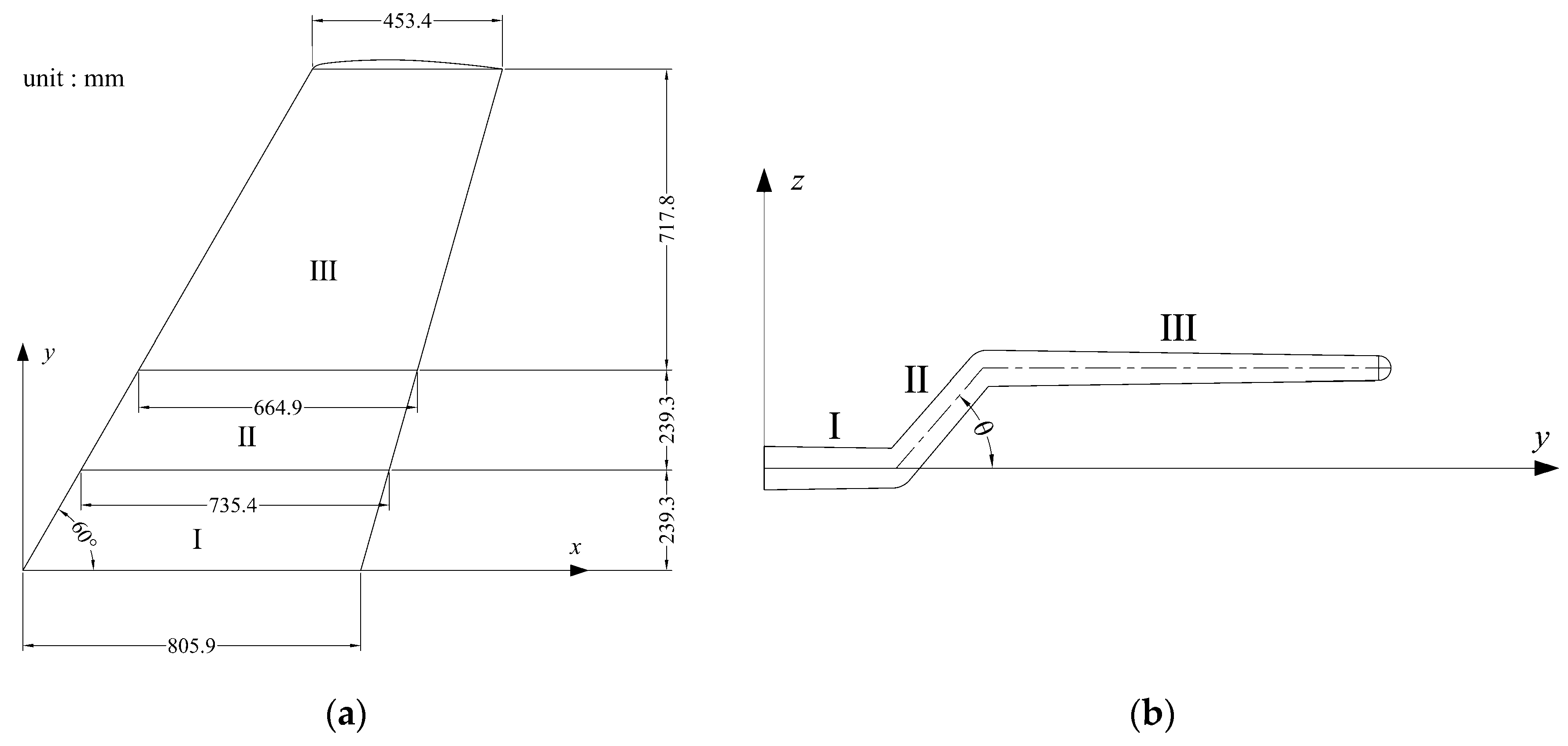
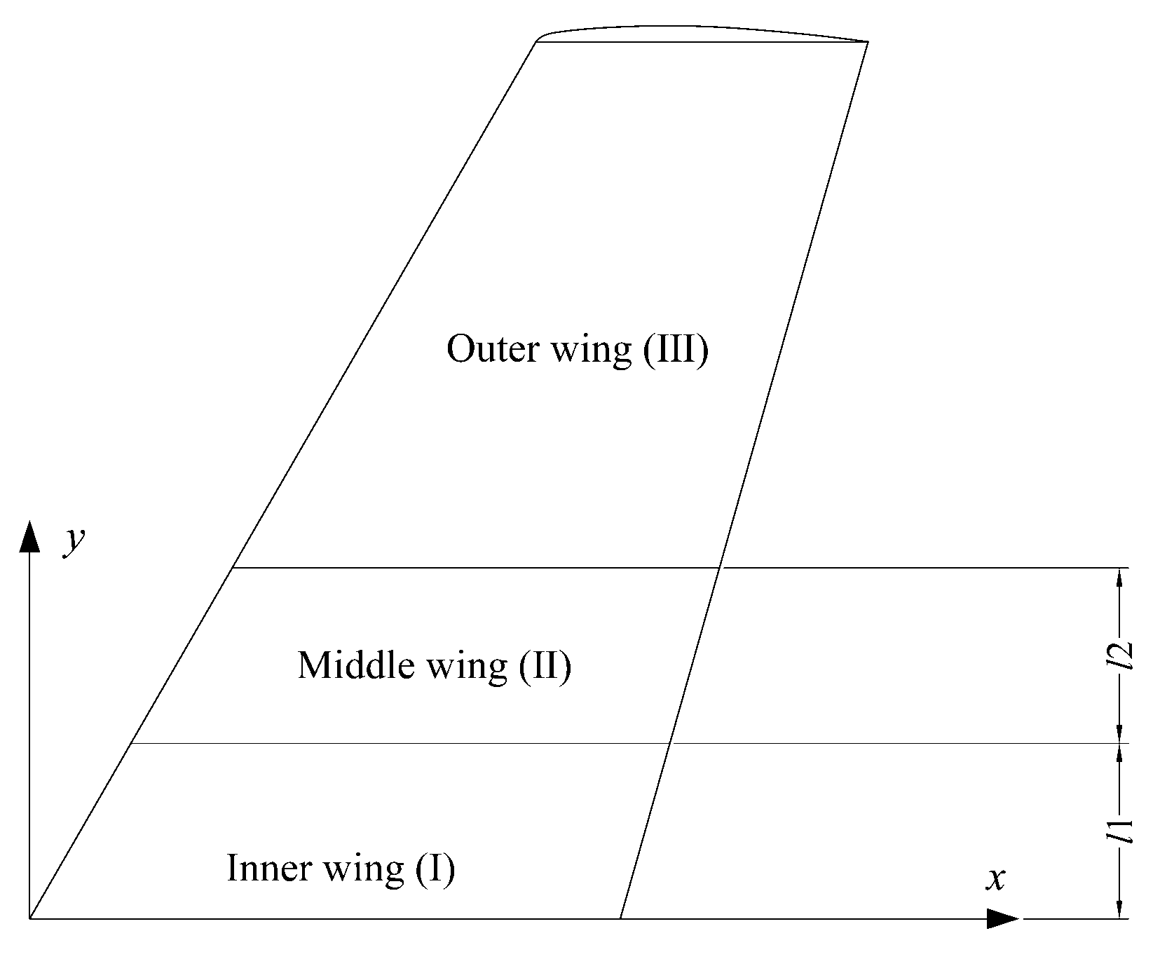
2.1.1. Model of Folding Wing Aircraft

The current study utilizes a three-dimensional model of the ONERA M6 wing with a thick trailing edge for numerical simulation; this underwent testing in an experiment conducted by the Advisory Group for Aerospace Research and Development (AGARD) of the North Atlantic Treaty Organization (NATO) in 1979. The wing’s shape and dimensions are depicted in Figure 1a. To enable the folding of the wing, the model is divided into three parts: the inner wing (I), middle wing (II), and outer wing (III), as shown in Figure 2, where the inner wing is situated at the 0–20% span of the wing model, while the middle part is located at 20–40% of the wing model. During the folding process, the inner wing remains stationary, and the outer wing is parallel to the inner wing. The folding angle θ is the rotation angle of the middle wing with respect to the inner wing, as shown in Figure 1b. Moreover, the aileron is excluded from the model. For further information regarding the ONERA M6 wing, please refer to reference [21].

2.1.2. Definition of the Folding Motion

The folding process of the wing involves a continuous dynamic change in the aerodynamic shape. Therefore, it is necessary to define the wall mesh caused by the folding motion prior to employing the CFD method in this process. Additionally, the appropriate solving domain and mesh type should be adjusted in response to the large-scale movement of the wall, especially if the folding angle changes in a short period of time. To ensure the middle wing maintains a fixed thickness during the folding process, there are nodes in motion between each pair of parts to facilitate smooth wing folding.
During the folding process, the nodes’ coordinates of the wing surface are assumed to be ( x 0 , y 0 , z 0 ) when the wing is unfolded and ( x , y , z ) when the wing is folding. According to the model presented above, the following initial morphing formula is described by Xu et al. [13]:
For Part I:
x = x 0 y = y 0 y 0 l 1 z 0 tan θ 2 z = z 0
For Part II:
x = x 0 y = l 1 + y 0 l 1 cos θ z 0 tan θ 2 z = z 0 + y 0 l 1 sin θ
For Part III:
x = x 0 y = y 0 l 2 l 2 cos θ l 1 + l 2 + l 3 y 0 l 3 z 0 tan θ 2 z = z 0 + l 2 sin θ
The wing folding process can be effectively described by formulas that incorporate the spans of the inner wing ( l 1 ), middle wing ( l 2 ), and outer wing ( l 3 ), and achieve a suitable aerodynamic shape, which is beneficial to obtaining the unsteady solution of the flow field.
In the morphing process, this study employs a combination of fluent dynamic mesh and User-Defined Functions (UDFs). UDFs are used to define the node motion during the wing-folding process, and the dynamic mesh UDFs work according to the macro “DEFINE_GRID_MOTION”. However, when using “DEFINE_GRID_MOTION”, the coordinates can only be updated based on the previous time step’s position rather than the initial coordinates according to the above formulas. Consequently, the formulas can be written in the following form:
For Part I:
x n + 1 = x n y n + 1 = y n + y n z n l 1 z n tan θ n 2 tan θ n 2 tan θ n + 1 2 z n + 1 = z n
For Part II:
x n + 1 = x n y n + 1 = y n + y n l 1 + z n tan θ n 2 cos θ n + sin θ n tan θ n 2 cos θ n + 1 cos θ n z n y n l 1 + z n tan θ n 2 sin θ n cos θ n + sin θ n tan θ n 2 tan θ n + 1 2 tan θ n 2 z n + 1 = z n + y n l 1 + z n tan θ n 2 cos θ n + sin θ n tan θ n 2 sin θ n + 1 sin θ n
For Part III:
x n + 1 = x n y n + 1 = y n + l 2 cos θ n + 1 cos θ n + l 1 + l 2 + l 3 l 3 y n + l 2 l 2 cos θ n + l 1 + l 2 + l 3 l 3 z n l 2 sin θ n tan θ n 2 l 3 + z n l 2 sin θ n tan θ n 2 z n l 2 sin θ n tan θ n 2 tan θ n + 1 2 z n + 1 = z n + l 2 sin θ n + 1 sin θ n
where ( x n + 1 , y n + 1 , z n + 1 , θ n + 1 ) are the nodes’ coordinates and folding angle at the current time step, while ( x n , y n , z n , θ n ) are their corresponding values at the previous time step. Furthermore, the nodes’ coordinates are updated at each time step based on their previous positions by the UDFs. It is necessary to note that the UDFs must define the time-varying folding position to ensure that the model updates correctly, which can be achieved by defining ( l 2 , l 3 ) as time-varying variables.

2.1.3. Numerical Simulation Method

In this study, the aerodynamic characteristics of the folding wing are simulated using the pressure-based Reynolds-Averaged Navier–Stokes equation with the Spalart–Allmaras (S–A) turbulence model. To deal with the large-scale wall motion of the folding wing, a diffusion-based smoothing technique is used in the dynamic mesh setting. Moreover, the quality of the internal mesh is improved by the local remeshing method during the folding process. The locations of the nodes on the boundary of the folding wing are updated using Equations (4)–(6), and the meshes in the flow field domain are reconstructed accordingly. Since the available remeshing methods in Ansys Fluent only work for triangular–tetrahedral zones and mixed zones, the volume mesh of the wing model is created using tetrahedral meshes with 15 boundary layers of the last-ratio offset method type. Based on test 2308 of AGARD’s report [21], the initial flow conditions are presented in Table 1, corresponding to a Reynolds number of 11.72 million with a mean aerodynamic chord of 0.64607 m. The boundaries at the surface of the wing are specified as a ‘wall’ boundary conditions, while the boundary at the symmetry plane is specified as a ‘symmetry’ boundary condition, which is equivalent to a ‘wall’ boundary condition. Meanwhile, the boundaries at the far-field are specified as ‘pressure far-field’ boundary conditions. The dimensionless variable y + represents the distance from the wall to the first grid cell’s center. Since the first mesh layer of the wall can be meshed into the viscous sublayer in the S–A model under high Reynolds number conditions, y + < 10 when a low Reynolds number scheme is used. In Ansys Fluent, the S–A model has a y + insensitive wall treatment, so y + is taken as 5 in these conditions, with a corresponding first boundary layer height of 7.15 × 10⁻⁶ m. The used mesh and computational flow domain are shown in Figure 3, with an overall mesh size of 14,917,671 cells.

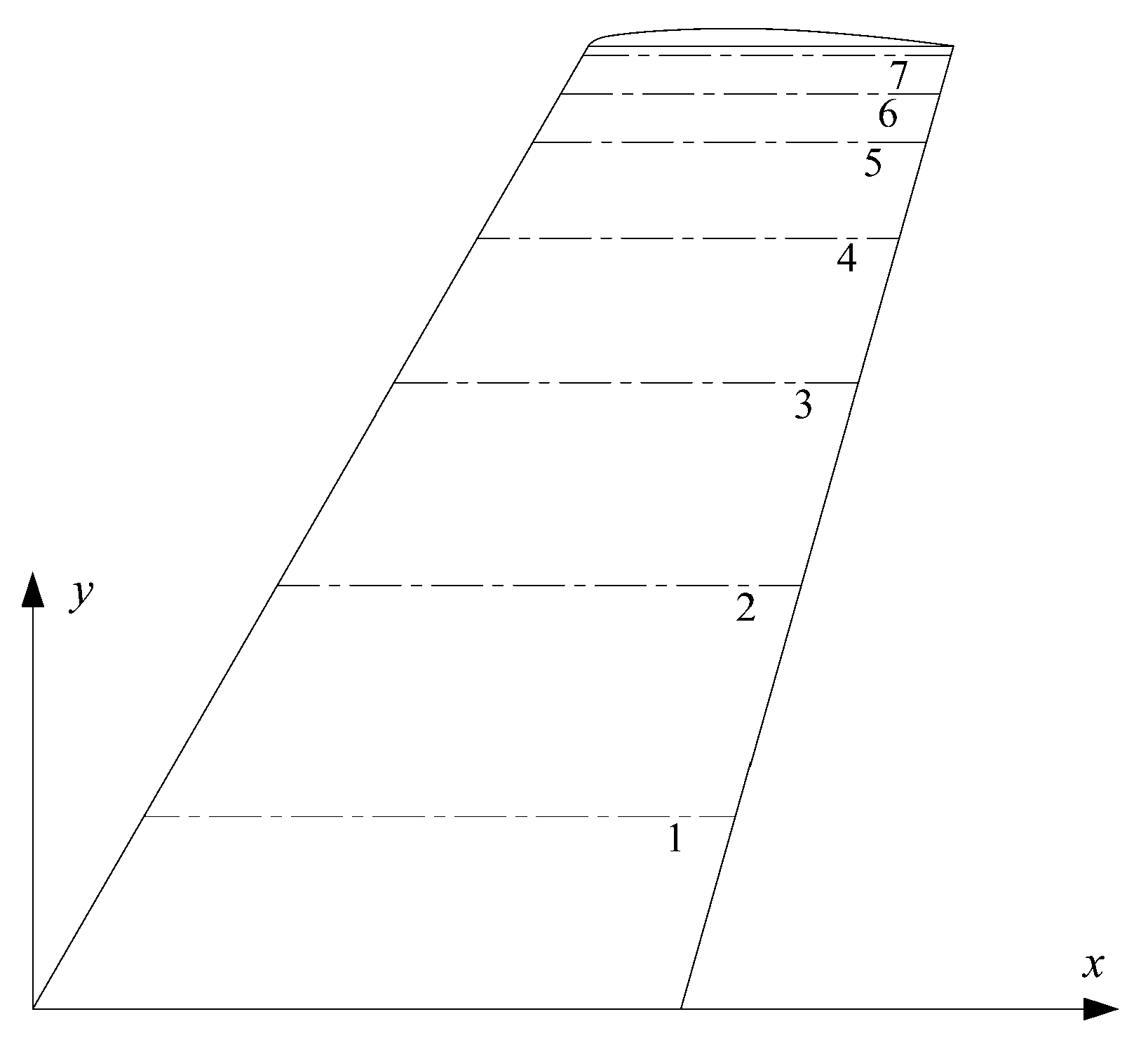
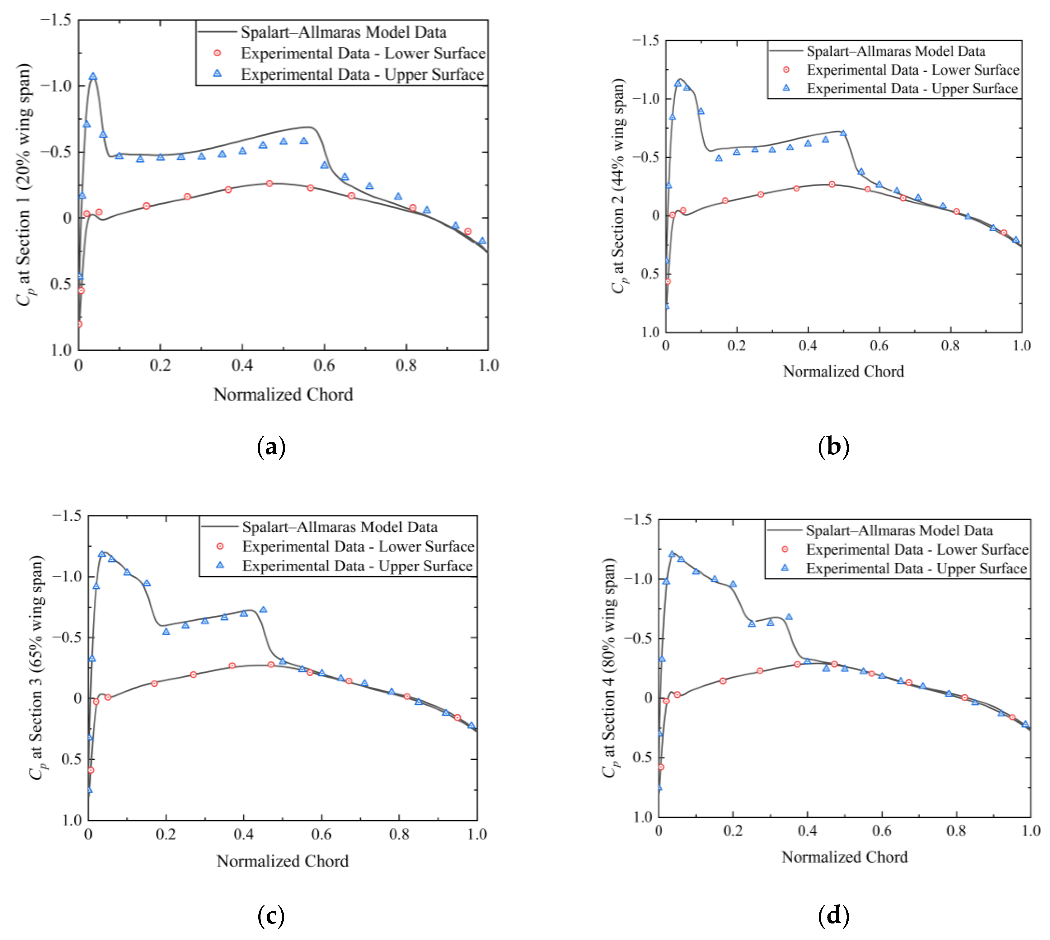
2.2. Validation of the Model in Steady State

In the AGARD’s experiment, pressure coefficients are measured at seven different locations on the ONERA M6 wing model [21], which is divided into sections along its span, as depicted in Figure 4 and detailed in Table 2. Previous studies have conducted a comparative analysis between the accuracy of CFD methods and experimental data using the same wing model [22,23]. The current study encompasses a validation of the model by comparing the pressure coefficients obtained from CFD simulations with the experimental data for each of the seven sections along both the upper and lower surfaces of the wing, where the distance of the y-coordinate position of each section from the origin is defined as y, the span is defined as b, and the sections are defined with y/b (ratio of y and b). The comparison results, depicted in Figure 5, demonstrate a close match between the curves of the upper and lower surfaces for most sections and the corresponding experimental data. Minimal differences are observed at two specific locations: the merged shock region on the upper wing at y/b = 0.95 and the trailing edge on the upper wing at y/b = 0.99.
Based on this comparison, it is determined that the S–A turbulence model utilized in this paper, as well as the mesh, are valid with small errors compared to the experimental values under the aforementioned freestream conditions. Moving forward, the steady aerodynamic characteristics of the folded and unfolded wing will be investigated, followed by an analysis of the unsteady aerodynamic characteristics of the Z-shaped folding wing during the folding process.

3. Results and Discussion

3.1. The Steady Aerodynamic Characteristics of Folding Wing

The aerodynamic characteristics of the folding wing with a 75 degree folding angle and the unfolded ONERA M6 wing are numerically studied. Figure 6 illustrates the aerodynamic coefficients of the folded and unfolded wings at various angle-of-attack values (α) under freestream conditions.
In Figure 6a, the lift coefficients increase with an increase in the angle of attack. Notably, the unfolded wing exhibits significantly higher lift coefficients compared to the folded wing. Turning to the drag coefficient, as depicted in Figure 6b, the folded wing experiences slightly higher drag coefficients than the unfolded wing at low angles of attack. However, as the angle of attack increases, the drag coefficient of the unfolded wing exhibits a faster rate of increase compared to that of the folded wing, eventually surpassing it.
The lift-to-drag ratio is presented in Figure 6c, showcasing an initial growth followed by a gradual decrease for both wing configurations. Generally, the folded wing demonstrates a lower lift-to-drag ratio compared to the unfolded wing. At its peak, the folded wing’s lift-to-drag ratio is 50% lower than that of the unfolded wing. Nevertheless, as the angle of attack increases, the difference between the two ratios gradually diminishes.
Examining the pitching moment coefficient at a 1/4 chord length in Figure 6d, both wings generate a nose-down pitching moment with an increase in the angle of attack. Specifically, the folded wing exhibits a nose-down pitching moment at an angle of attack of 0 degrees, while the unfolded wing demonstrates almost no moment at the same angle. However, as the angle of attack increases, the nose-down pitching moment of the folded wing becomes smaller than that of the unfolded wing. This characteristic enhances the control efficiency and maneuverability of the aircraft.
To further investigate the aerodynamic characteristics of the folded and unfolded wings in steady state at previous freestream conditions (Table 1). Figure 7 presents a comparison of the pressure coefficients at seven different positions, revealing notable discrepancies in the calculated results within the middle wing. Specifically, these differences are primarily observed in the negative pressure region near the leading edge and in proximity to the shockwave.
Furthermore, Figure 8 compares the pressure coefficient distribution of both configurations under the aforementioned flow field conditions. The results indicate that the pressure distribution on the folded wing’s middle section does not transition as uniformly to the inner and outer wings when compared to the unfolded wing.
At a high subsonic speed, a noteworthy occurrence takes place on the upper surface of the unfolded wing, wherein localized supersonic regions emerge, leading to the formation of a λ-shock [24,25], as depicted in Figure 9a. Simultaneously, under the current freestream conditions and angle of attack, it is observed that the wingtip vortices and vortices resulting from flow separation on the upper surface of the wing exhibit a tendency to coalesce. Regarding the folded wing, under similar conditions, the λ-shock remains present, but the flow separation vortices visibly coalesce at the wing folding location. This leads to the formation of a larger vortex and a smaller vortex at the two folding positions, which corresponds to the observations depicted in Figure 7a,b. To summarize, when operating at high subsonic conditions, the folded wing produces an additional shockwave at the folded position compared to the unfolded wing. Additionally, airflow separation generates extra vortices at two folded positions of the wing. However, the pressure coefficient distribution at other wing positions in the folded configuration remains similar to that of the unfolded wing. Consequently, it can be inferred that the reduction in the effective lift area of the wing, coupled with flow separation at the folded position, contributes to the diminished lift.

3.2. The Unsteady Aerodynamic Characteristics of Folding Wing

In this section, the analysis focuses on the unsteady aerodynamic characteristics of the Z-shaped folding wing in a single upward folding motion. The folding angle is set to 75 degrees with a constant folding angular velocity, taking into account the mesh quality after the dynamic mesh update. The wing’s folding time refers to the time needed for the transition from the unfolded wing state to the state in which the folding angle reaches 75° to take place. This study examines three distinct folding speeds with corresponding folding times: 0.5 s, 1 s, and 2 s. The impact of the wing’s folding speed on the unsteady aerodynamic characteristics is discussed at a low angle of attack (3.06°).
Figure 10 illustrates the unsteady aerodynamic coefficients of the Z-shaped folding wing at various folding speeds. Initially, from 0 to 1 s, the wing remains stationary to allow the aerodynamic coefficients to reach steady-state values. Consequently, the aerodynamic coefficients begin to deviate from the steady-state values.
Figure 10a reveals that the lift coefficients at all folding speeds increase with the folding angle at the beginning. After a period of small oscillations, they display an initial upward trend followed by a gradual decrease. It is noteworthy that the lift coefficient increases slightly as the folding speed becomes slower during ascent. The decrease in the lift coefficients for all three folding speeds occurred near a folding angle of approximately 40° to 45°, and a relatively delayed decrease was observed at a folding speed of 0.5 s. The slower the folding speed, the earlier this decreasing trend occurred. Eventually, the lift coefficients for the three folding speeds converge to the same value after the descent phase.
Concerning the drag coefficients, they increase with the folding angle for each folding speed at the beginning. Similar to the lift coefficients, they exhibit an initial rising phase with small oscillations, followed by a sharp drop at a folding angle of around 40° to 45°. During the ascent phase, there is a greater drag coefficient at slower folding speeds. However, the sharp drop in the drag coefficient is delayed at a 0.5 s folding speed, and relatively, this sharp drop occurs earlier at a 2 s folding speed. Eventually, the drag coefficients for the three folding speeds approach a common value after the drop period.
Regarding the lift-to-drag ratio, all ratios show a general downward trend, which intensifies at folding angles of 40° to 45°. Notably, the increase in the decreasing trend of the lift-to-drag ratio is relatively delayed as the folding speed increases.
Lastly, concerning the pitching moment, the nose-down pitching moments for all folding speeds initially display an increasing trend. The nose-down pitching moments are slightly lower at a faster folding speed. At a folding angle of approximately 40° to 45°, a significant decrease in the nose-down pitching moments of all folding speeds occurs, with a relatively delayed decrease observed as the folding speed increases.
Generally, an increase in the folding angle results in a relatively flat change for each aerodynamic coefficient until reaching 40°. However, beyond this point, the trend in the aerodynamic coefficients becomes steep, typically between 40° and 45°. Similarly, like the steady-state outcomes, the lift-to-drag ratio exhibits a decline with increasing folding angles. Furthermore, the nose-down pitching moment experiences a slight increase until 40°, but ultimately decreases as the wing is fully folded. These observations suggest that, as the folding angle increases, the advantageous lift-to-drag ratio of the wing is continuously compromised. Nevertheless, this trade-off ultimately leads to improved control efficiency and maneuverability.

4. Conclusions

This study compares the steady-state aerodynamic characteristics of the Z-shaped folding wing with those of the conventional wing. Additionally, it analyzes the unsteady aerodynamic characteristics of the Z-shaped folding wing during the upward folding process. The effects on the unsteady aerodynamic characteristics are discussed at three different folding speeds in this paper.
(1)
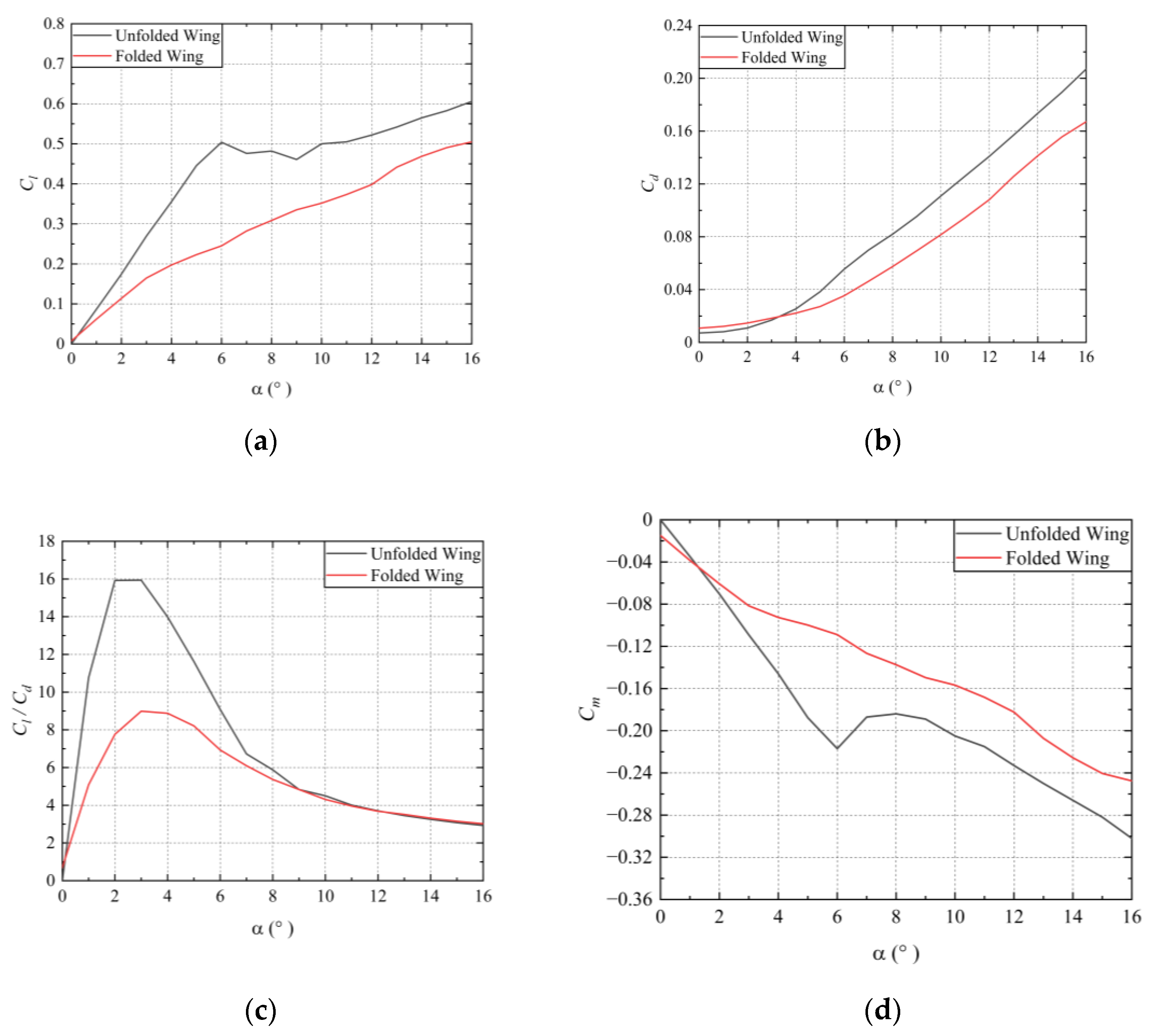
For the steady aerodynamic characteristics, when the wing is folded at an angle of 75°, the lift coefficient of the folded wing is smaller than that of the unfolded wing at various angle of attacks. Conversely, the drag coefficient of the folded wing is slightly larger than that of the unfolded wing at low angles of attack, but it gradually becomes smaller as the angle of attack increases. Moreover, the folded wing exhibits a smaller lift-to-drag ratio compared to the unfolded wing at different angles of attack. Regarding the pitching moment coefficient, the folded wing experiences a smaller nose-down pitching moment in comparison to the unfolded wing as the angle of attack increases.
(2)
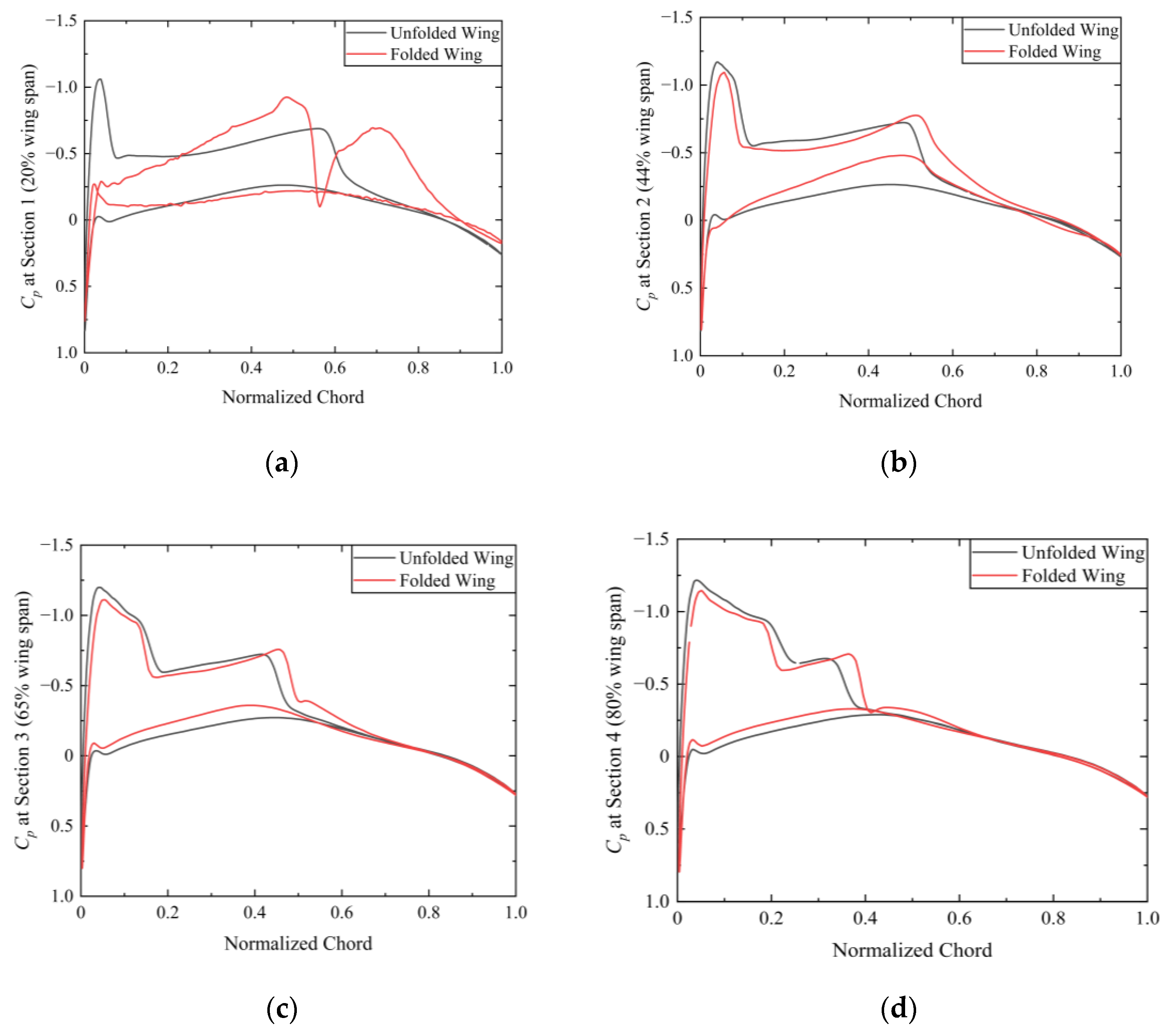
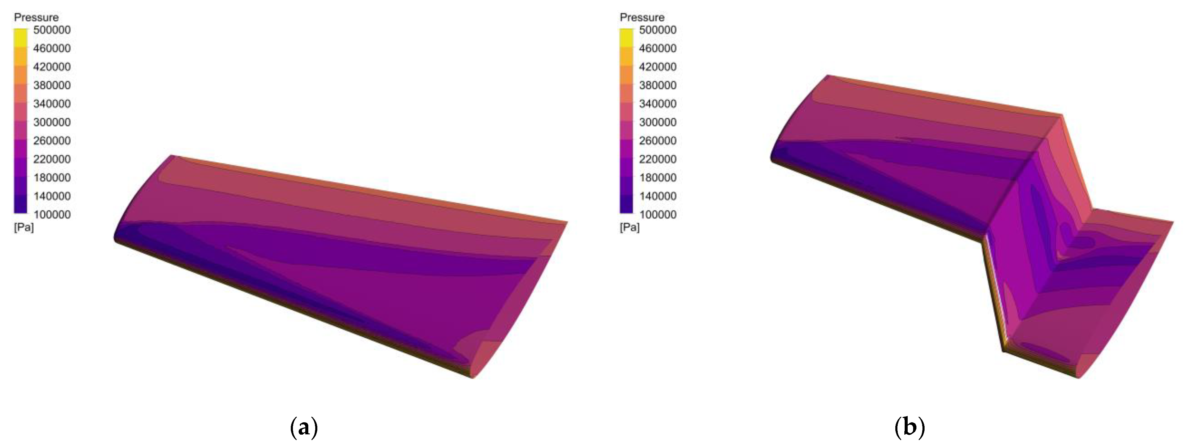
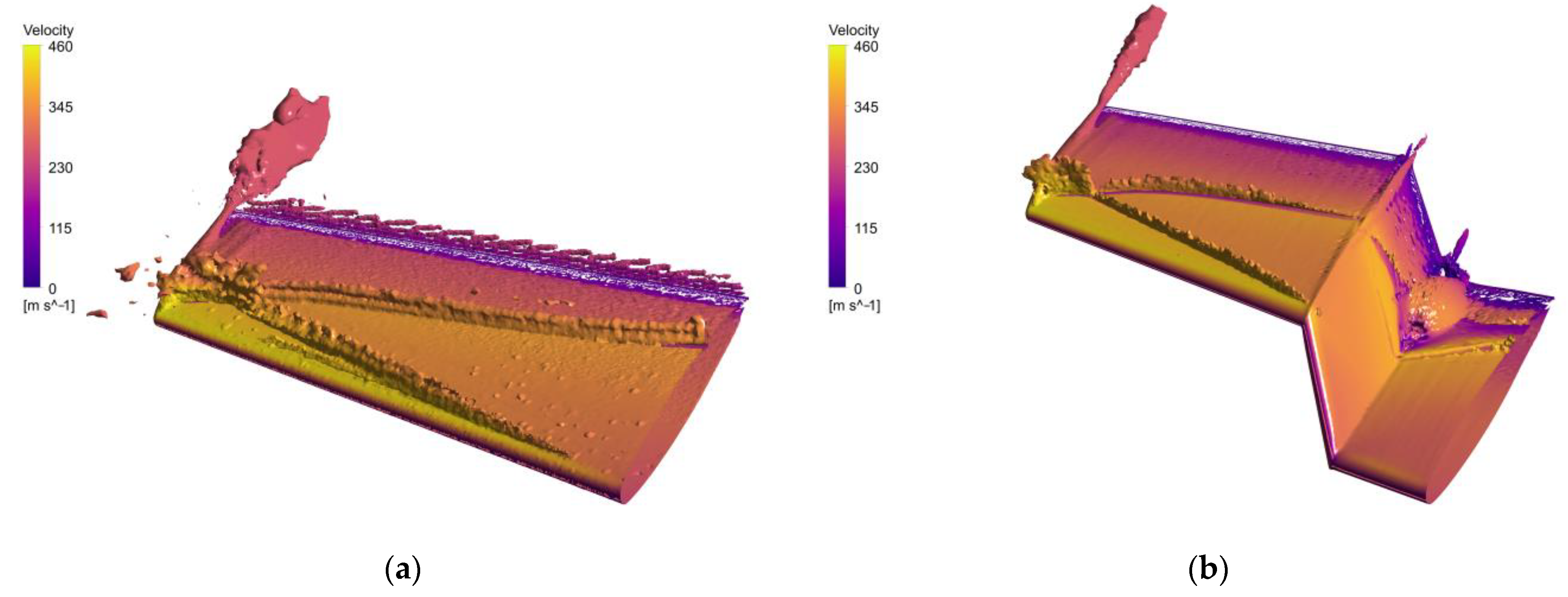
Regarding the steady aerodynamic characteristics, the difference between the pressure coefficients of the folded wing and the unfolded wing is primarily focused on the wing’s folding position. Specifically, under high subsonic flight conditions, local supersonic regions are generated. In addition to the λ-shock generated by an unfolded wing under the same conditions, a folded wing also generates additional shock waves. The flow separation coalesces to form two vortices at the folded position, which may contribute to the lower lift-to-drag ratio of the folded wing, in addition to the reduced lift area.
(3)
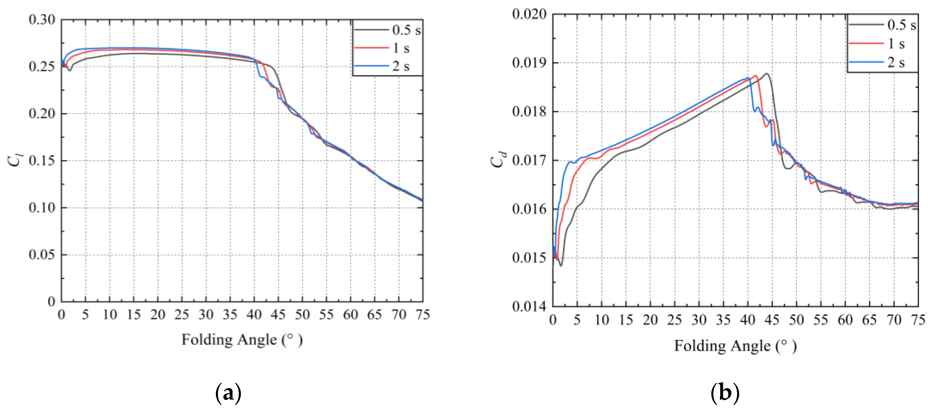
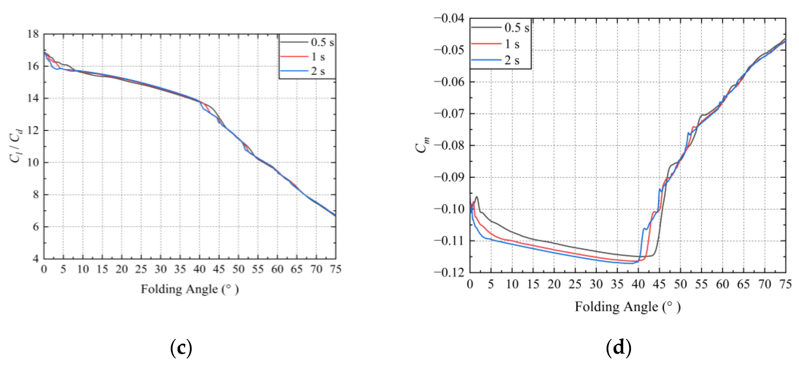
Concerning the unsteady aerodynamic characteristics, the aerodynamic coefficients of the wing are compared at three different folding speeds. It is observed that during the folding process, the aerodynamic coefficients do not vary significantly with an increasing folding speed, and their changes remain consistent. However, at approximately 40° to 45°, the trends in the aerodynamic coefficients undergo a significant shift, and this shift is advanced as the folding speed decreases. Eventually, the aerodynamic coefficients at the three different folding speeds converge to the same value. Generally, as the wing folds, the folding wing compromises its lift-to-drag ratio characteristics to achieve a smaller nose-down pitching moment, thereby enhancing maneuverability.

Author Contributions

Conceptualization, Y.H. and X.G.; methodology, Y.H.; software, Y.H.; validation, Y.H.; formal analysis, Y.H.; investigation, Y.H.; resources, Y.H. and X.G.; data curation, X.G. and D.C.; writing—original draft preparation, Y.H. and X.G.; writing—review and editing, Y.H., X.G. and D.C.; visualization, Y.H.; supervision, X.G. and D.C.; project administration, X.G. and D.C.; funding acquisition, X.G. and D.C. All authors have read and agreed to the published version of the manuscript.

Funding

This research was funded by National Natural Science Foundation of China, grant numbers 12172014 and 11972050.

Data Availability Statement

Not applicable.

Conflicts of Interest

The authors declare no conflict of interest.

References

  1. Kan, Z.; Li, D.; Shen, T.; Xiang, J.; Zhang, L. Aerodynamic characteristics of morphing wing with flexible leading-edge. Chin. J. Aeronaut. 2020, 33, 2610–2619. [Google Scholar] [CrossRef]
  2. Abdessemed, C.; Bouferrouk, A.; Yao, Y. Effects of an unsteady morphing wing with seamless side-edge transition on aerodynamic performance. Energies 2022, 15, 1093. [Google Scholar] [CrossRef]
  3. Courchesne, S.; Popov, A.; Botez, R. New Aeroelastic Studies for a Morphing Wing. In Proceedings of the 48th AIAA Aerospace Sciences Meeting Including the New Horizons Forum and Aerospace Exposition, Orlando, FL, USA, USA, 4–7 January 2010. [Google Scholar]
  4. Coutu, D.; Brailovski, V.; Terriault, P.; Mamou, M.; Mebarki, Y. Aerostructural Model for Morphing Laminar Wing Optimization in a Wind Tunnel. J. Aircr. 2011, 48, 66–76. [Google Scholar] [CrossRef]
  5. Prabhakar, N.; Prazenica, R.J.; Gudmundsson, S.; Balas, M.J. Transient dynamic analysis and control of a morphing UAV. In Proceedings of the AIAA Guidance, Navigation, and Control Conference, San Diego, CA, USA, 4–8 January 2016; p. 893. [Google Scholar]
  6. Santos, P.; Sousa, J.; Gamboa, P. Variable-span wing development for improved flight performance. J. Intell. Mater. Syst. Struct. 2017, 28, 961–978. [Google Scholar] [CrossRef]
  7. Raither, W.; Heymanns, M.; Bergamini, A.; Ermanni, P. Morphing wing structure with controllable twist based on adaptive bending–twist coupling. Smart Mater. Struct. 2013, 22, 065017. [Google Scholar] [CrossRef]
  8. Bishay, P.L.; Aguilar, C. Parametric Study of a Composite Skin for a Twist-Morphing Wing. Aerospace 2021, 8, 259. [Google Scholar] [CrossRef]
  9. Ivanco, T.; Scott, R.; Love, M.; Zink, S.; Weisshaar, T. Validation of the Lockheed Martin Morphing Concept with Wind Tunnel Testing. In Proceedings of the 48th AIAA/ASME/ASCE/AHS/ASC Structures, Structural Dynamics, and Materials Conference, Honolulu, HI, USA, 23–26 April 2007. [Google Scholar]
  10. Ortiz, P.; Alley, N. Spanwise Adaptive Wing-PTERA Flight Test. In Proceedings of the AIAA Aviation Forum, Atlanta, GA, USA, 25–29 June 2018. [Google Scholar]
  11. Hassanalian, M.; Abdelkefi, A.; Wei, M.; Ziaei-Rad, S. A novel methodology for wing sizing of bio-inspired flapping wing micro air vehicles: Theory and prototype. Acta Mech. 2017, 228, 1097–1113. [Google Scholar] [CrossRef]
  12. Healy, F.; Cheung, R.; Neofet, T.; Lowenberg, M.; Rezgui, D.; Cooper, J.; Castrichini, A.; Wilson, T. Folding Wingtips for Improved Roll Performance. J. Aircr. 2022, 59, 15–28. [Google Scholar] [CrossRef]
  13. Xu, H.; Han, J.; Xi, Y.; Chen, G.; Cao, P. Comparative Study of Lifting Surface and CFD Methods in the Simulation of Morphing Process of Folding Wing. Int. J. Aerosp. Eng. 2022, 2022, 2476196. [Google Scholar] [CrossRef]
  14. Zhou, Z.; Huang, J. Z-folding aircraft electromagnetic scattering analysis based on hybrid grid matrix transformation. Sci. Rep. 2022, 12, 4452. [Google Scholar] [CrossRef] [PubMed]
  15. Guo, X.; Zhang, Y.; Zhang, W.; Sun, L. Theoretical and experimental investigation on the nonlinear vibration behavior of Z-shaped folded plates with inner resonance. Eng. Struct. 2019, 182, 123–140. [Google Scholar] [CrossRef]
  16. Zhao, J.; Zeng, L.; Shao, X. A novel prediction method for unsteady aerodynamic force on three-dimensional folding wing aircraft. Aerosp. Sci. Technol. 2023, 137, 108287. [Google Scholar] [CrossRef]
  17. Gao, L.; Zhu, Y.; Liu, Y.; Zhang, J.; Liu, B.; Zhao, J. Analysis and Control for the Mode Transition of Tandem-Wing Aircraft with Variable Sweep. Aerospace 2022, 9, 463. [Google Scholar] [CrossRef]
  18. Xu, H.; Han, J.; Yun, H.; Chen, X. Calculation of the Hinge Moments of a Folding Wing Aircraft during the Flight-Folding Process. Int. J. Aerosp. Eng. 2019, 2019, 9362629. [Google Scholar] [CrossRef]
  19. Changchuan, X.; Zhiying, C.; Chao, A. Aeroelastic Response of a Z-Shaped Folding Wing During the Morphing Process. AIAA J. 2022, 60, 3166–3179. [Google Scholar] [CrossRef]
  20. Abdessemed, C.; Yao, Y.; Abdessalem, B.; Narayan, P. Morphing airfoils analysis using dynamic meshing. Int. J. Numer. Methods Heat Fluid Flow 2018, 5, 1117–1133. [Google Scholar] [CrossRef]
  21. Schmitt, V.; Charpin, F. Pressure Distributions on the ONERA M6 Wing at Transonic Mach Numbers. Experimental Data Base for Computer Program Assessment: Report of the Fluid Dynamics Panel Working Group 04; No.: AR-138 Report; NATO Research and Technology Organisation AGARD: Brussels, Belgium, 1979. [Google Scholar]
  22. Balan, A.; Park, M.A.; Anderson, W.K.; Kamenetskiy, D.S.; Krakos, J.A.; Michal, T.; Alauzet, F. Verification of anisotropic mesh adaptation for turbulent simulations over ONERA M6 wing. AIAA J. 2020, 58, 1550–1565. [Google Scholar] [CrossRef]
  23. Munshi, A.; Sulaeman, E.; Omar, N.; Ali, M.Y. CFD analysis on the effect of winglet cant angle on aerodynamics of ONERA M6 wing. J. Adv. Res. Fluid Mech. Therm. Sci. 2018, 45, 44–54. [Google Scholar]
  24. Kuzmin, A. On the lambda-shock formation on ONERA M6 wing. Int. J. Appl. Eng. Res. 2014, 9, 7029–7038. [Google Scholar]
  25. Chainok, S.; Rungroch, T.; Chairach, P.; Prapamonthon, P.; Yooyen, S.; Yin, B.; Yang, G.; Ju, S. Parametric Study on Wing-Lambda-Shock Formation. In Proceedings of the ASME 2021 Fluids Engineering Division Summer Meeting, Virtual, 10–12 August 2021. [Google Scholar]
Figure 1. Model of ONERA M6 wing: (a) shape and dimensions; (b) definition of the folding angle.
Aerospace 10 00749 g001
Figure 2. Division of the folding wing model.
Aerospace 10 00749 g002
Figure 3. ORENA M6 wing meshed: (a) wing mesh; (b) mesh of trailing edge; (c) mesh of leading edge; (d) computational flow domain for wing.
Aerospace 10 00749 g003
Figure 4. The seven sections of the ONERA M6 wing.
Aerospace 10 00749 g004
Figure 5. Comparison of the S–A model results and experimental data: (a) y/b = 0.2; (b) y/b = 0.44; (c) y/b = 0.65; (d) y/b = 0.8; (e) y/b = 0.9; (f) y/b = 0.95; (g) y/b = 0.99.
Aerospace 10 00749 g005aAerospace 10 00749 g005b
Figure 6. Aerodynamic coefficients for ONERA M6 wing in the folded and unfolded states: (a) lift coefficient; (b) drag coefficient; (c) lift-to-drag ratio; (d) pitching moment coefficient.
Aerospace 10 00749 g006
Figure 7. Comparison of Cp between folded and unfolded wing at seven locations: (a) y/b = 0.2; (b) y/b = 0.44; (c) y/b = 0.65; (d) y/b = 0.8; (e) y/b = 0.9; (f) y/b = 0.95; (g) y/b = 0.99.
Aerospace 10 00749 g007aAerospace 10 00749 g007b
Figure 8. Upper-side Cp distribution for ONERA M6 wing in the folded and unfolded state: (a) unfolded wing; (b) folded wing.
Aerospace 10 00749 g008
Figure 9. Iso-surfaces of the q-criterion colored with velocity contours on folded and unfolded wings: (a) unfolded wing; (b) folded wing.
Aerospace 10 00749 g009
Figure 10. Unsteady aerodynamic characteristics during upward folding process: (a) lift coefficient; (b) drag coefficient; (c) lift-to-drag ratio; (d) pitching moment coefficient.
Aerospace 10 00749 g010aAerospace 10 00749 g010b
Table 1. Freestream conditions.
MachReynolds NumberAngle of Attack (deg)Angle of Sideslip (deg)Temperature (R)Pressure (psia)
0.839511.72 × 1063.06046045.82899
Table 2. The locations for plotting the pressure coefficients.
Sectiony/by (mm)
10.2239.26
20.44526.372
30.65777.595
40.8957.04
50.91076.67
60.951136.485
70.991184.337
Disclaimer/Publisher’s Note: The statements, opinions and data contained in all publications are solely those of the individual author(s) and contributor(s) and not of MDPI and/or the editor(s). MDPI and/or the editor(s) disclaim responsibility for any injury to people or property resulting from any ideas, methods, instructions or products referred to in the content.

