Article

Fluid–Structure Coupling and Aerodynamic Performance of a Multi-Dimensional Morphing Wing with Flexible Metastructure Skin

1
Parallel Robot and Mechatronic System Laboratory of Hebei Province, Yanshan University, Qinhuangdao 066004, China
2
State Key Laboratory of Robotics and System, Harbin Institute of Technology, Harbin 150001, China
*
Authors to whom correspondence should be addressed.
Aerospace 2023, 10(8), 678; https://doi.org/10.3390/aerospace10080678
Submission received: 17 June 2023 / Revised: 17 July 2023 / Accepted: 17 July 2023 / Published: 30 July 2023
(This article belongs to the Special Issue Cross-Domain Intelligent Flight Vehicle Design)

Abstract

:
A multi-dimensional morphing wing skeleton mechanism is proposed with double-sided triangular pyramid units, which can realize continuous variable span-wise bend, span-wise twist, and sweep. A lockable morphing unit is designed, and its mechanism/structure characteristics, degree of freedom, and the deformable function of its deformable wing skeleton mechanism are analyzed. One kind of flexible skin is proposed to meet the performance requirements, consisting of an internal metastructure and a flexible surface bonded on both sides. The morphing wing skeleton mechanism and the equivalent treated metastructure flexible skin are then combined. Subsequently, a two-way fluid–structure interaction analysis is conducted to investigate the influence of aerodynamic loads on the flexible skin and skeleton mechanism in different deformation states, including the influence of structural passive deformation on the aerodynamic characteristics of the morphing wing. The computational fluid dynamics method is employed to analyze the aerodynamic characteristics of the morphing wing in its initial state, as well as in three deformation states, and to study its aerodynamic performance in different flight environments.

1. Introduction

Variable geometry aircrafts have many advantages due to their excellent flight efficiency and performance, including efficient penetration, quick response, high endurance, and far field transportation. In addition, variable geometry aircrafts have broad application prospects in the aerospace vehicle field and will play a vital role in future aircraft development. As one of the key technologies of variable geometry aircrafts, morphing wing technology has been extensively studied in developing high-performance variable geometry aircrafts. The internal deformable skeleton mechanism and flexible skin are the key technologies for achieving deformation and maintaining the aerodynamic shape of the morphing wing. This article proposes a distributed-drive deformable wing skeleton mechanism and a corresponding metastructure flexible skin that can achieve multi-dimensional deformation. This proposal is based on the development trend of morphing wing technology and the aerodynamic requirements of various flight fields for morphing wing.
A morphing wing prototype with a variable airfoil profile thickness in a real wing size was proposed by Kammegne et al. [1]. Four identical micro-electromechanical actuators were installed on the middle two wing ribs of the prototype. The shape of the flexible skin on the upper surface of the wing was changed through the vertical displacement of the actuator to improve the air flow. Fasel et al. [2] reported a flexible variable trailing edge camber morphing wing based on a composite material. This morphing wing realized the differential deformation of the wingspan, flexible maneuvering, and control. The flight test verified the improvement in rolling efficiency. Xi et al. [3,4] studied a wing chord camber-deformed morphing wing based on a reconfigurable mechanism structure. Then, two deformation driving schemes were compared. The Tu-160 supersonic bomber developed by the Soviet Union [5] and the American F-14 Tomcat fighter jet adopted a variable swept wing of wing root rotation [6]. The variable swept wing has excellent low-speed take-off and landing and high-speed penetration characteristics and controllability. From an aerodynamics perspective, the variable swept wing provides an effective method for reducing the aerodynamic drag caused by air compression at the subsonic, transonic, and supersonic stages of an aircraft, thus obtaining a higher lift–drag ratio.
NextGen conducted a flight and wind tunnel test of the variable swept wing aircraft MFX-1 under the funding of the variant aircraft structure “MAS” program [7]. A hydraulic driver placed inside each parallelogrammatic connecting-rod mechanism drove the morphing wing deformation. The flexible skin uses a carbon fiber silicone reinforcement material that can be shear-deformed, and a swept angle of 15°–45° can be achieved in flight tests within 15 s. Jenett et al [8] designed a modular and reversibly assembled wing that performed continuous span-wise twist deformation. Lightweight and high-strength carbon fiber lattice cells were used to support the morphing wing. The morphing wing had a −10° to 10° twist in the wind tunnel experiment, which exhibited higher roll efficiency and aerodynamic characteristics than a conventional rigid aileron system. Lockheed Martin developed a folding wing, which enabled variations of span-wise length, aspect ratio, and effective sweep angle, significantly increasing mission performance compared with conventional aircrafts [9]. Considering the need of large sweep deformation and high stiffness characteristics, a morphing wing driven by distributed parallel linkage was proposed by Yang et al. [10,11], which enabled variations in chord length, area, and aspect ratio. However, the above-mentioned morphing wing research mainly focuses on the thickness and camber deformation of the two-dimensional airfoil profile; sweep, wingspan bending, or folding deformations of the three-dimensional wing and other single morphing functions. It is still difficult to meet the requirements of a multi-function aerodynamic shape and large deformation of aircrafts in complex flight environments.
The deformation function of the morphing wing flexible skin can be realized in three main ways [12]: the deformation of the elastic material itself [13], the sliding or rotating deformation of the mechanism, and the large deformation of the sandwich composite structure. A hybrid material flexible skin of a Kevlar/carbon-fiber-reinforced silica gel matrix for a shear swept morphing wing was proposed by Yu et al. [14]. The difficulty lay in ensuring that folds and wrinkles were avoided during shear deformation. Lockheed Martin developed a seamless flexible skin with foldable deformation and memory function [9]. A discrete slip-deformed skin for variable geometry wings was proposed by Xi et al. [15,16], which was different from elastic skin and was designed to discretize the relative sliding motion between rigid plates to deformation. However, the gap and size of the discrete rigid plates required by each deformation form are different. Yokozeki et al. [17] developed a corrugated flexible skin structure of chord direction camber morphing wing. A rigid bar was added to the bottom of the corrugated structure to enhance the stiffness of the wingspan direction. In addition, flexible rubber was filled on one side to ensure a smooth and continuous surface. Metastructure has the advantages of lightweight structure, in-plane low stiffness, large deformation, high out-of-plane stiffness and good heat insulation, vibration drag, and energy absorption [18,19,20]. A zero Poisson’s ratio hybrid metastructure flexible skin and accordion metastructure flexible skin were proposed by Olympio et al. [21]. Based on the advantages of metastructure characteristics, Bubert et al. [22] proposed a metastructure composite skin that consists of a zero Poisson’s ratio metastructure as the support core and a flexible silicone panel as the surface layer. This design allows for wingspan direction large deformation while maintaining the continuous smoothness of the airfoil. The existing research shows that flexible skin can achieve large deformation, but the bearing capacity is low and the fatigue damage is easy; or that flexible skin can effectively provide out-of-plane stiffness, but the deformation ability is not ideal and the driving force demand is too large. The metastructure morphing skin is an effective solution to realize the variability of the deformed wing, bear and transmit the aerodynamic load, and ensure the smooth continuity and airtightness of the airfoil. It has the advantages of high out-of-plane bearing capacity and low driving force. However, there are also the shortcomings of small deformation and the need to cover the elastomer to ensure a smooth surface. Therefore, it is necessary to focus on the design of its in-plane deformation capacity and out-of-plane aerodynamic carrying capacity.
This study proposes a morphing wing skeleton (MWS) mechanism with modular bilateral triangular pyramid (BTP) units. The MWS mechanism not only provides three different morphing functions, but also has high stiffness and stability. Through modular design and distributed drive, the MWS mechanism can achieve local or global multi-dimensional continuous smooth deformation. Distributed drive can effectively reduce the local excessive driving force demand. Compared to other morphing mechanisms, this MWS mechanism has a simple structure, distributed drive, multi-dimensional morphing, and modular expansion. The rest of this paper is organized as follows. Section 2 presents the structure and metastructure flexible skin of the MWS mechanism. Section 3 proposes a discrete multifunctional distributed drive continuous multi-dimensional deformation MWS mechanism. The deformable truss is taken as the basic unit, which has the characteristics of high bearing capacity. Furthermore, a new hybrid metastructure flexible skin with adjustable Poisson’s ratio is designed to meet the requirements of continuous and smooth flexible morphing wing on the surface, high out-of-plane stiffness, and low in-plane stiffness characteristics. Aerodynamic characteristics are analyzed for the multi-dimensional MWS mechanism and flexible skin. Research on the smooth continuous flexible morphing wing is of great significance.

2. Design of the MWS Mechanism and Metastructure Flexible Skin

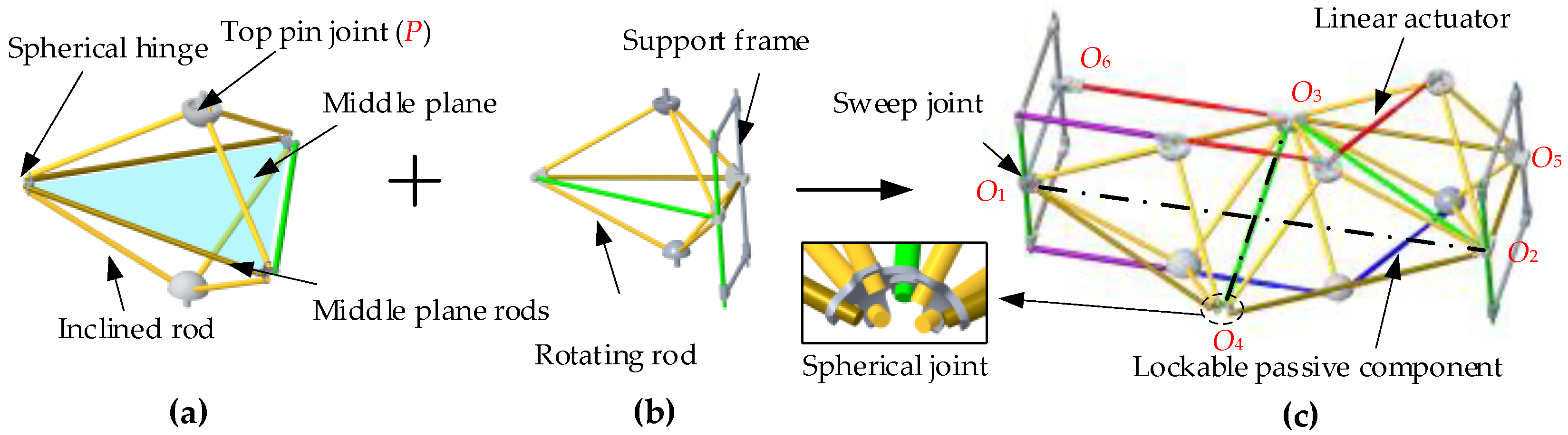
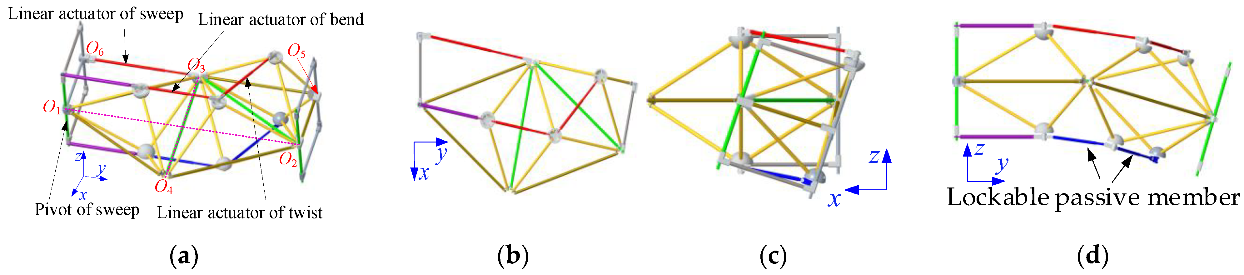
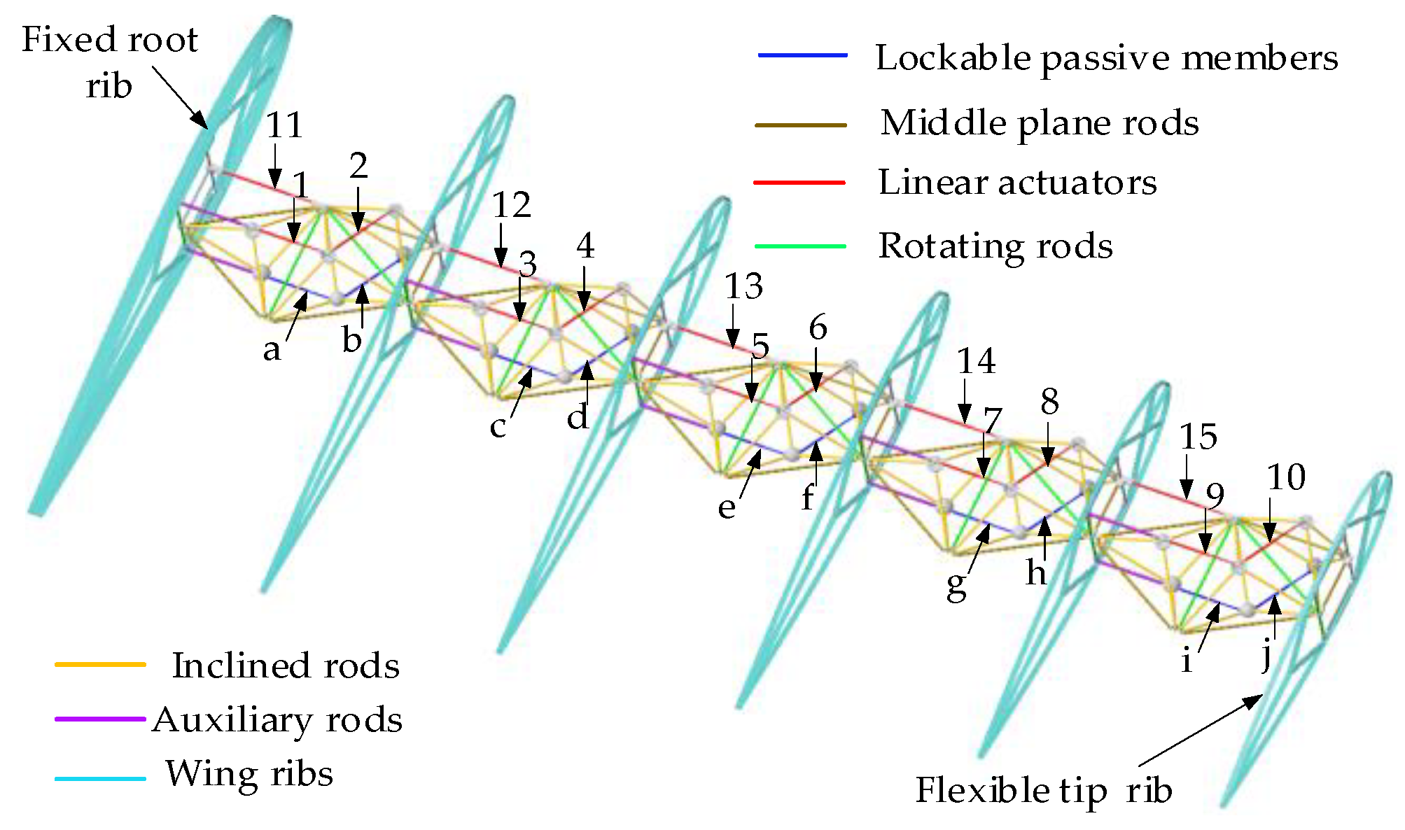
2.1. Structure Design of the MWS Mechanism

The modular BTP unit consists of two top pin joints (P), three spherical hinges, six inclined rods, one rotating rod, and two middle plane rods, as shown in Figure 1a. It is important to note that the BTP unit is symmetrical with the middle plane. Figure 1b depicts a 1/2 BTP unit connected to the wing rib support frame for wing rib installation. By connecting two BTP units and the 1/2 BTP unit with a rotating rod and spherical joints, a lockable morphing (LM) unit is formed, as shown in Figure 1c. To ensure stability post-morphing, a lockable passive member is added to enhance the structure’s stiffness and stability. Within the LM unit, a linear actuator is connected to two top pin joints. It is worth mentioning that both the lockable passive member and linear actuator are symmetrically arranged with respect to the plane O3O1O2.
Figure 2 illustrates the reconfigurability of the LM unit through changes in the configuration of the linear actuator and lockable passive member. In the initial position, represented by Figure 2a, the left-wing rib support frame is fixed. The swept-back linear actuator is elongated to achieve swept-back deformation, as shown in Figure 2b. Similarly, the twisting linear actuator is extended to achieve twisting deformation, as shown in Figure 2c. The span-wise bending linear actuator is extended to achieve span-wise bending deformation, as shown in Figure 2d.
Figure 3 shows the MWS mechanism, which includes multiple LM units and multiple wing ribs distributed along the wing span. The wing ribs are securely connected to the wing rib support frame on the LM unit. In the MWS mechanism, the first LM unit forms the swept deformation root mechanism by connecting to the wing rib at the fuselage base through a sweep angle hinge, a rotating rod, a sweep linear actuator, and an auxiliary rod. Likewise, two LM units are connected by the same parts to form a continuous swept deformation mechanism along the span direction.
The MWS mechanism only needs to design the corresponding wing rib shape and add flexible skin to obtain a complete morphing wing, without the need for additional mechanisms/structures, which greatly reduces the structural quality of the morphing wing. Additionally, through the optimized design of joints and ribs, further lightweight of the morphing wing is attainable. By capitalizing on the reconfigurable characteristics of the LM unit, the MWS mechanism not only provides a morphing function but also imparts stiffness and stability, thereby replacing the traditional wing box. Under corresponding driving configurations, the MWS mechanism demonstrates three distinct morphing functions. Through modular design and distributed drive, the morphing wing can achieve continuous and smooth multi-dimensional deformation locally or globally. Distributed driving can effectively reduce the local excessive driving force demand.

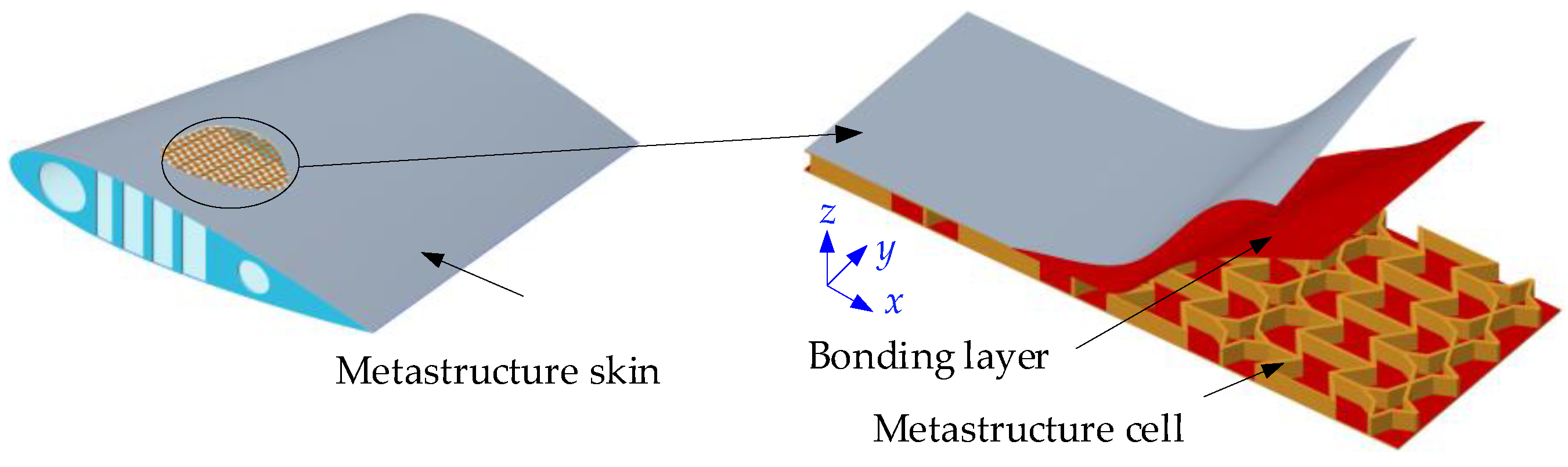
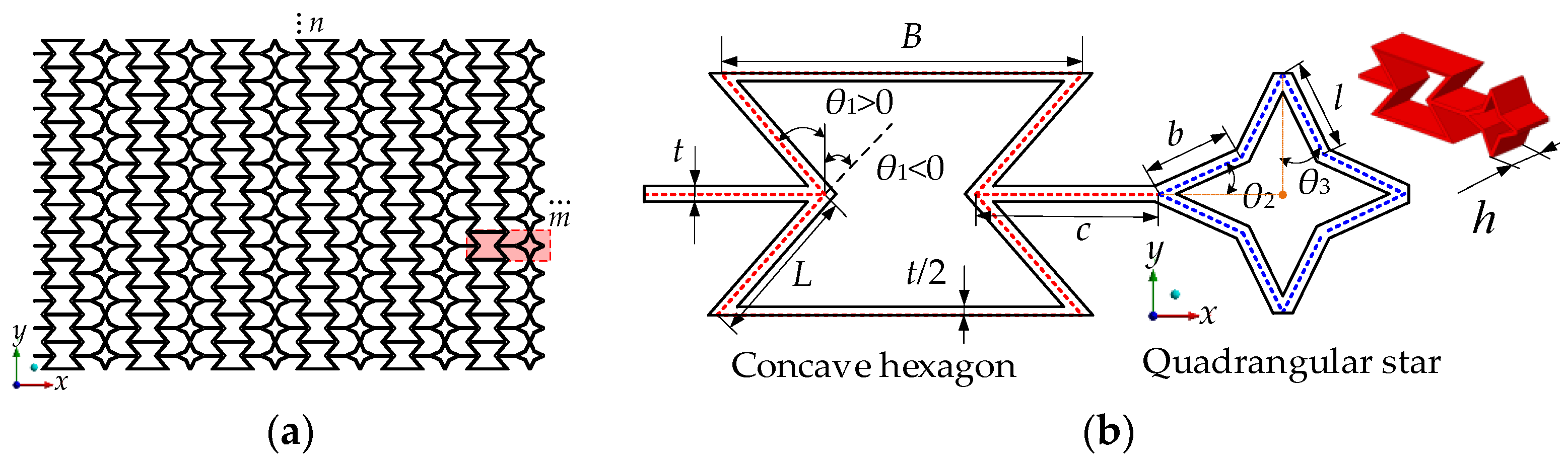
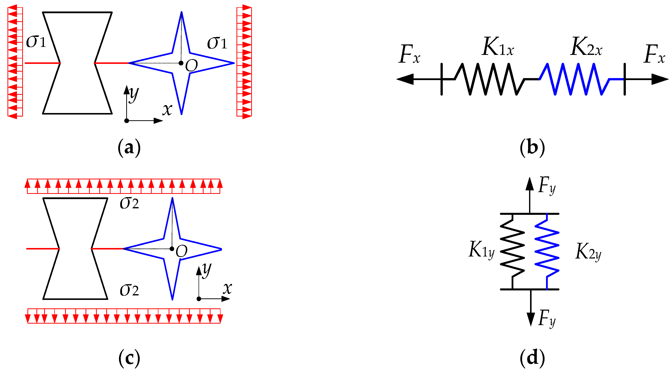
2.2. Design and Analysis of Skin Mechanical Characteristics

The metastructure flexible skin is composed of hybrid metastructure cells and flexible superficial skin, as shown in Figure 4. The flexible superficial skin and metastructure cells are connected by a bonding layer. The hybrid metastructure cells ensure low in-plane stiffness and high out-of-plane stiffness. The flexible superficial skin maintains the smoothness and air tightness of the morphing wing. The hybrid metastructure cell consists of a concave hexagon and a quadrangular star cell unit, as shown in Figure 5, which has periodic topological laws. m and n are the number of the cell units along the x- and y-axis directions. The concave hexagon and the quadrangular star cell unit have horizontal and vertical symmetry properties.
The relative density of the hybrid metastructure skin is as follows:
ρ r = ρ ρ s = β α 2 + 2 + α 1 / 2 + 2 α 3 + 2 α 4 2 L d cos θ 1
where Ld is a dimensionless quantity, Ld = α2 + α1/2 − sinθ1 + α3cosθ2 + α4sinθ3, L is the concave-inclined wall length of the concave hexagon, B is the horizontal wall length of the concave hexagon, c is the connected sheet length, θ1 is the inner angle of the concave hexagon cell unit, l and b are different sloping wall lengths of the quadrangular star, θ2 and θ3 are different cell unit inner angles of the quadrangular star, t is the thickness of cell wall, h is the depth of the hybrid metastructure, α1 = B/L, α2 = c/L, α3 = b/L, α4 = l/L, β = t/L, γ = h/L are dimensionless quantities, ρ* is the hybrid metastructure equivalent density, ρs is the base material density of the hybrid metastructure, A* is the actual bearing area in the xy-plane of the hybrid metastructure, As is the equivalent section area of the cell unit, and Lx is the cell unit length along the x-axis direction of the hybrid metastructure, Lx = 2c + B − 2L sinθ1 + 2bcosθ2 + 2lsinθ3.
The equivalent stiffness of hybrid metastructure cell is shown in Figure 6. The homogeneous load σ1 and σ2 are applied along the x- and y-axis directions. The homogenous load can be equivalent to the tension Fx and Fy applied to the series and parallel springs.
The relative Young’s modulus and Poisson’s ratio of the concave hexagon cell unit are as follows:
E 1 x E s = β 3 ( α 2 + α 1 / 2 sin θ 1 ) cos θ 1 λ 1 x E 1 y E s = β 3 cos θ 1 ( α 2 + α 1 / 2 sin θ 1 ) λ 1 y ν 1 x y = u 1 x ( α 2 + α 1 / 2 sin θ 1 ) cos θ 1 ν 1 y x = u 1 y cos θ 1 α 2 + α 1 / 2 sin θ 1
where E1x/Es is the relative Young’s modulus of the concave hexagon cell unit along thet x-axis direction, E1y/Es is the relative Young’s modulus of the concave hexagon cell unit along the y-axis direction, v1xy and v1yx are Poisson’s ratio, λ1x = cos2θ1 + β2sin2θ1 + 2α2β2, λ1y = sin2θ1 + β2cos2θ1, u1x = (1 − β2) sin(2θ1)/(2λ1x), u1y = (1 − β2) sin(2θ1)/(2λ1y).
The elasticity and Poisson’s ratio of the quadrangular star cell unit relative modulus are as follows:
E 2 x E s = β 3 λ 2 x E 2 y E s = β 3 λ 2 y ν 2 x y = ε 2 x y ε 2 x = u b + u l 2 L λ 2 x ν 2 y x = ε 2 y x ε 2 y = u b + u l 2 L λ 2 y
where E2x/Es is the relative Young’s modulus of the quadrangular star cell unit along the x-axis direction, E2y/Es is the relative Young’s modulus of the quadrangular star cell unit along the y-axis direction, and v2xy and v2yx are the Poisson’s ratio, λ2x = α 3 2 (α3 + 3α4)sin2θ2 + α 4 2 (α4 + 3α3)cos2θ3 + β2(α3cos2θ2 + α4sin2θ3), λ2y = α 3 2 (α3 + 3α4)cos2θ2 + α 4 2 (α4 + 3α3)sin2θ3 + β2(α3sin2θ2 + α4cos2θ3).
Based on Equations (2) and (3), the relative Young’s modulus and Poisson’s ratio of the hybrid metastructure is as follows:
E x E s = β 3 L d cos θ 1 ( λ 1 x + λ 2 x ) E y E s = β 3 cos θ 1 ( λ 1 y + λ 2 y ) L d λ 1 y λ 2 y ν y x = ε y x ε y = v 1 + v 2 L d
where v1 = −u1ycosθ1, v2 = v2yx (α3cosθ2 + α4sinθ3).

3. Fluid–Structure Coupling Analysis of Morphing Wing

3.1. Equivalent Model of Metastructure Skin

Flexible skin mechanical characteristics are mainly affected by the hybrid metastructure cell unit size. The hybrid metastructure has two mutually perpendicular elastic planes of symmetry, which can be regarded as an orthogonal anisotropic material with nine independent stiffness coefficients. Moreover, the stiffness matrix C is as follows:
C = C 11 C 12 C 13 0 0 0 C 12 C 22 C 23 0 0 0 C 13 C 23 C 33 0 0 0 0 0 0 C 44 0 0 0 0 0 0 C 55 0 0 0 0 0 0 C 66
where Cij are stiffness coefficients.
Given that the out-of-plane thickness of the hybrid metastructure is much smaller than the in-plane length and width size, it can be treated as the sheet plane stress. Its in-plane two-dimensional stiffness matrix Q is written as follows:
Q = Q 11 Q 12 0 Q 12 Q 22 0 0 0 Q 66
where Qij are stiffness coefficients, which can be expressed as the engineering elastic constant.
Q 11 = E 1 1 ν 12 ν 21 , Q 22 = E 2 1 ν 12 ν 21 Q 12 = ν 21 E 2 1 ν 12 ν 21 , Q 66 = G 12
where E1 = Ex, E2 = Ey, v12 = vxy, v21 = vyx, G12 = Gxy can be obtained using the Euler–Bernoulli beam model.
The in-plane bend stiffness matrix D of the metastructure equivalent orthogonal anisotropic sheet is as follows:
D = D 11 D 12 0 D 12 D 22 0 0 0 D 66 = h 3 12 Q 11 Q 12 0 Q 12 Q 22 0 0 0 Q 66
where D11, D12, and D22 are bend stiffness coefficients, and D66 is the twist stiffness coefficient.
The deflection of the metastructure equivalent orthogonal anisotropic sheet, the size of which is a × b × h with four sides simply supported under the action of homogeneous load q0, is as follows:
w = 16 q 0 π 6 m = 1 , 3 , 5 n = 1 , 3 , 5 1 m n sin m π x a sin n π y b D 11 m a 4 + 2 D 12 + 2 D 66 m a 2 n b 2 + D 22 m b 4
where m and n are any positive integers, x and y are arbitrary position coordinates of the sheet.
It can be observed that the maximum deflection wmax occurs at x = a/2, y = b/2 in the center of the sheet. The x direction of the hybrid metastructure is along the wing chord direction, while the y direction is along the wingspan direction, as shown in Figure 7. h is the depth of the hybrid metastructure, and t2 is the thickness of the flexible skin and bonding layer. This arrangement method allows for smaller stiffness in the wingspan direction, reducing the driving force required for deformation. Furthermore, the skin’s zero Poisson’s ratio characteristics prevent chord direction wrinkle and the large in-plane Young’s modulus Ex to improve the flexible skin’s out-of-plane bearing capacity, as evidenced by Equation (9).
If the hybrid metastructure cell of the skin is directly used in modeling, the number of grids will be large, the calculation is slow, and the time is very long. To improve computational efficiency, the hybrid metastructure skin’s equivalent elastic modulus and Poisson’s ratio are applied to an orthogonal anisotropic sheet, so that the skin structure could be equivalent. First, the shell model is created in Ansys Workbench 2022 R1 software. Then, the mechanical elastic constant in Equation (7) is obtained through simulation. Subsequently, an equivalent orthogonal anisotropic material shell cell sheet model is constructed through the Ansys Composite Prep/Post (ACP) module of Ansys Workbench to simulate the mechanical characteristics of the hybrid metastructure. The basic parameters of the hybrid metastructure skin are as follows: L = 10 mm, α1 = 2.2, α2 = 1.1, β = 0.1, γ = 1.0, θ1= 50°, θ2 = 25°. Based on the analysis of boundary conditions in Section 2.2, v12 = vxy =0 is obtained. The mechanical elastic constants of the equivalent orthogonal anisotropic material are: Ex = 7447 MPa, Ey = 252 MPa, vyx = 0.0212, Ez = 47,810 MPa, and Gxy = 11 MPa, h + 2t = 12 mm. Both the hybrid metastructure sheet and equivalent orthogonal anisotropic material sheet are supported on four sides. The maximum deflection value of the overall out-of-plane under the 0.02 MPa homogeneous load is simulated, and the simulated results are listed in Table 1.
It is observed that the equivalent orthogonal anisotropic shell effectively simulates the mechanical characteristics of the hybrid metastructure skin. The equivalent shell unit can improve the computational efficiency of the subsequent simulation.

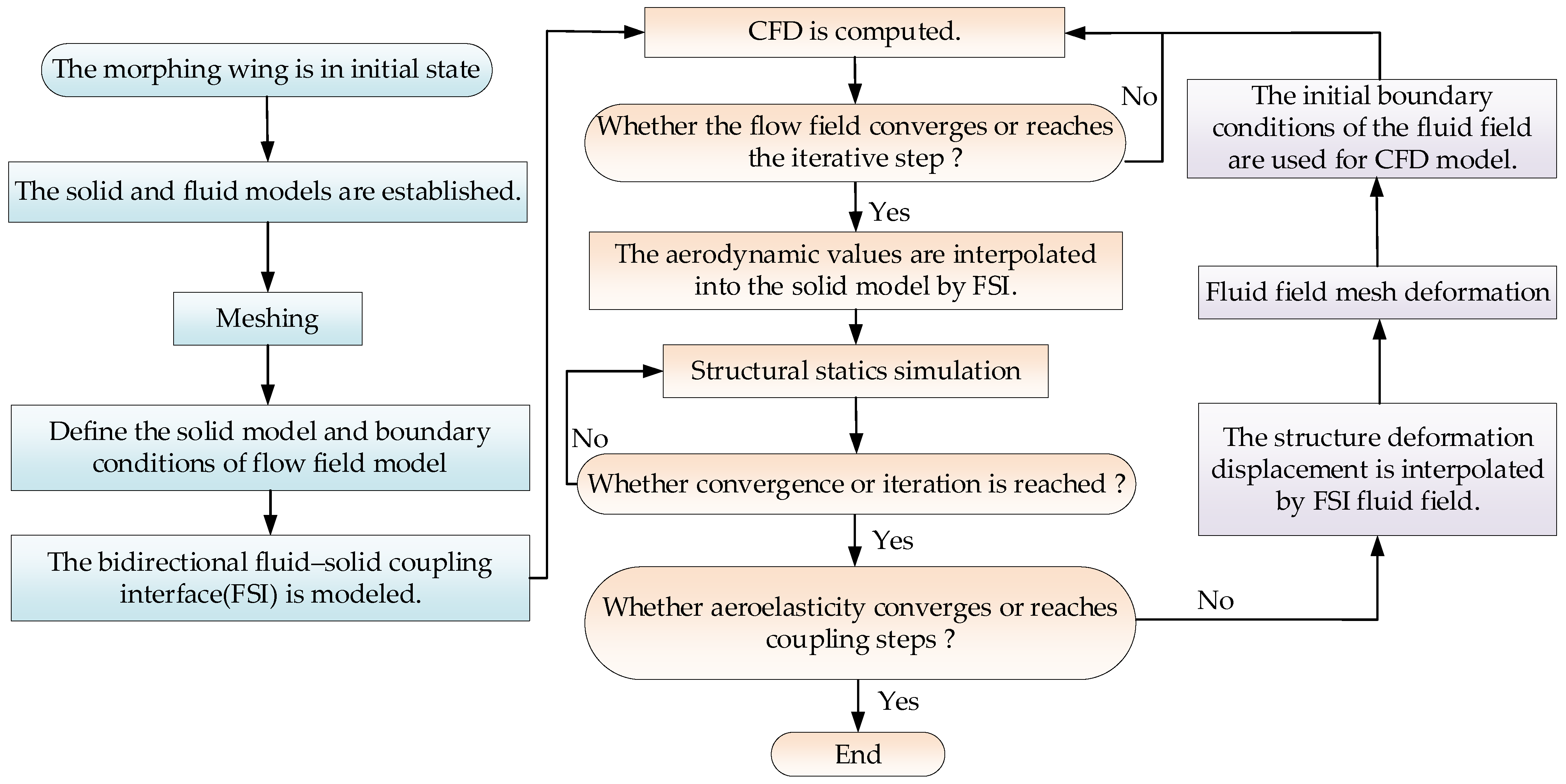
3.2. Bidirectional Fluid–Structure Coupling Analysis of the Morphing Wing

The coupling FEM model of the single MWS mechanism and flexible skin module was established using the Ansys Workbench 2022 R1 software. The bidirectional fluid–structure coupling interaction (FSI) analysis was performed in the coupling model. Four deformation states of the single-module skeleton mechanism and skin are shown in Figure 8. The structural and fluid simulation calculations of the morphing wing were completed using Transient Structural and Fluent 2022 R1 software, respectively. The dynamic bidirectional fluid–structure coupling analysis simulated platform was constructed on the Ansys workbench. Some characteristics of the MWS mechanism and flexible skin under the action of aerodynamic load were studied, that is, pressure, stress, and displacement distribution, and the influence of the flexible skin on the morphing wing aerodynamic characteristics after passive deformation. A flowchart for the numerical simulation of two-way FSI is shown in Figure 9.

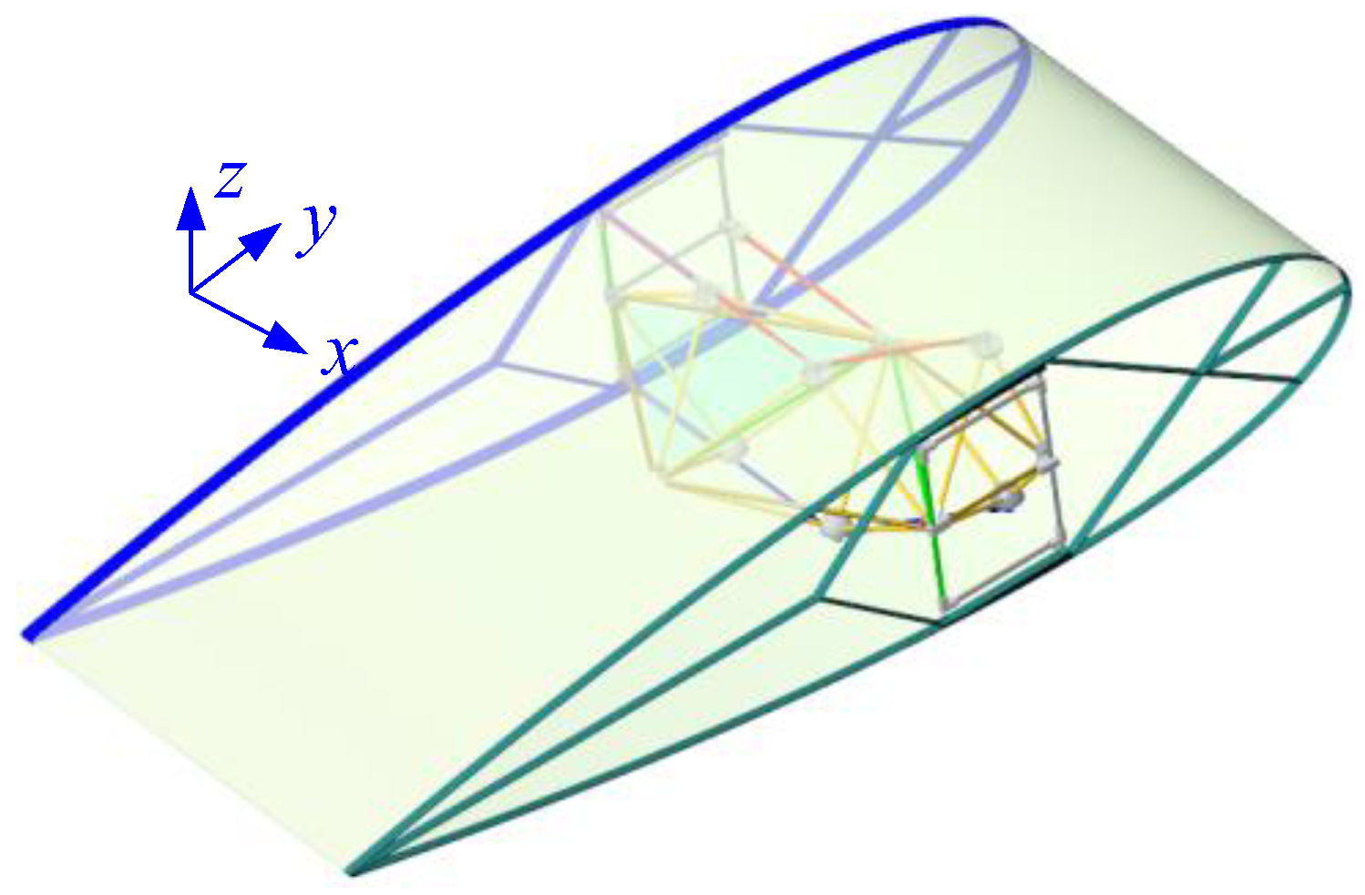
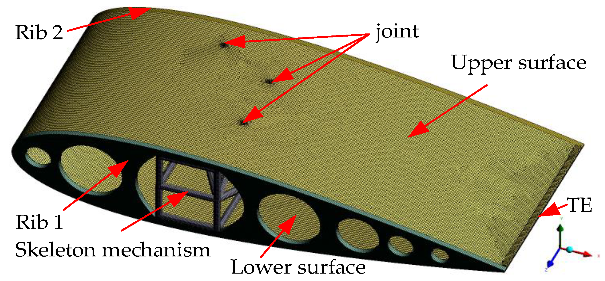
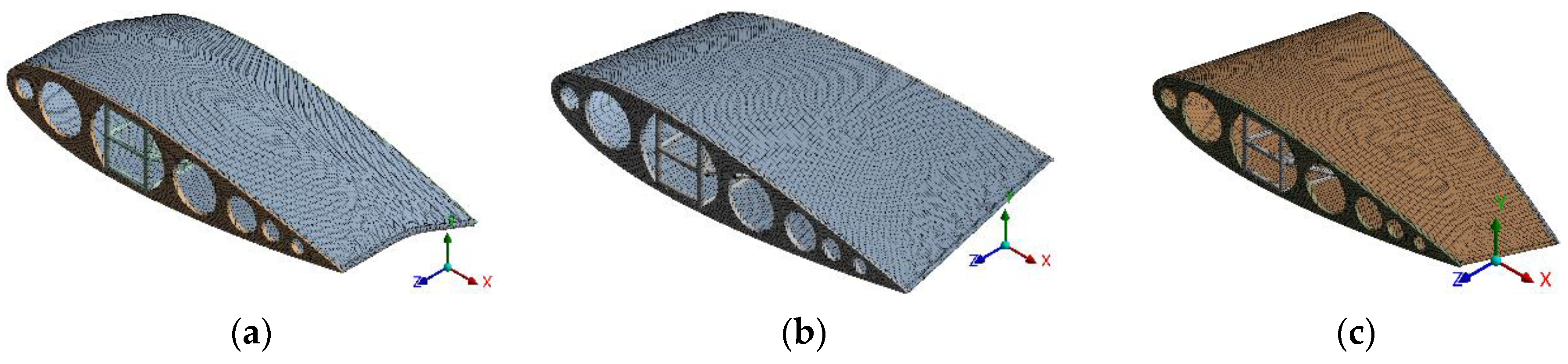
3.2.1. Morphing Wing FEM Model

The morphing wing consists of the MWS mechanism and the hybrid metastructure flexible skin. The skeleton mechanism is a complex multi-link truss, which supports the hybrid metastructure flexible skin and transfers the aerodynamic load. Each structural component should be simplified to reduce the complexity and efficiency of the simulation. The beams were used to simulate the link, driver, and lockable passive link. The shell element is used to simulate the rib and flexible skin. The bonded rods and rib are connected through node sharing. The flexible skin and rib are connected through bonded contact (bonded—MPC). The engineering elastic parameters of the shell element are endowed with the equivalent orthogonal anisotropic material. The rods and rib are connected and meshed. The processed flexible skin and skeleton mechanism are then imported into the same analysis component. Figure 10 shows the FEM model of the MWS mechanism and flexible skin coupling. TE represents the trailing edge of the wing.
The material rib is an aluminum alloy, with a density of 2.77 g/cm3, Young’s modulus of 71,000 MPa, Poisson’s ratio of 0.33, shearing Young’s modulus of 26,690 MPa, yield strength of 280 MPa, and strength of extension of 310 MPa. The material of the link is a carbon fiber composite, and the material properties are listed in Table 2.
In bidirectional fluid–structure coupling analysis, fluid and structure fields need to be calculated through several iterations. Therefore, the transient structural analysis system was used to solve the FEM structural model. Fluid–structure coupling analysis interfaces were created on the flexible skin. The rib and rods at the root of the morphing wing were fixed. The external load was applied to the flexible skin through the system coupling surface by the fluid–structure coupling analysis FSI interface. The beam section result, which is a setup method in the software, was opened in the solution step, and the solution time was set to 0.04 s to obtain the bearing and deformation of the flexible skin of the rod under aerodynamic load. Three FEM mesh models in deformation state are shown in Figure 11. The same method was used to set the boundary conditions and create the coupling interface corresponding to the fluid model.

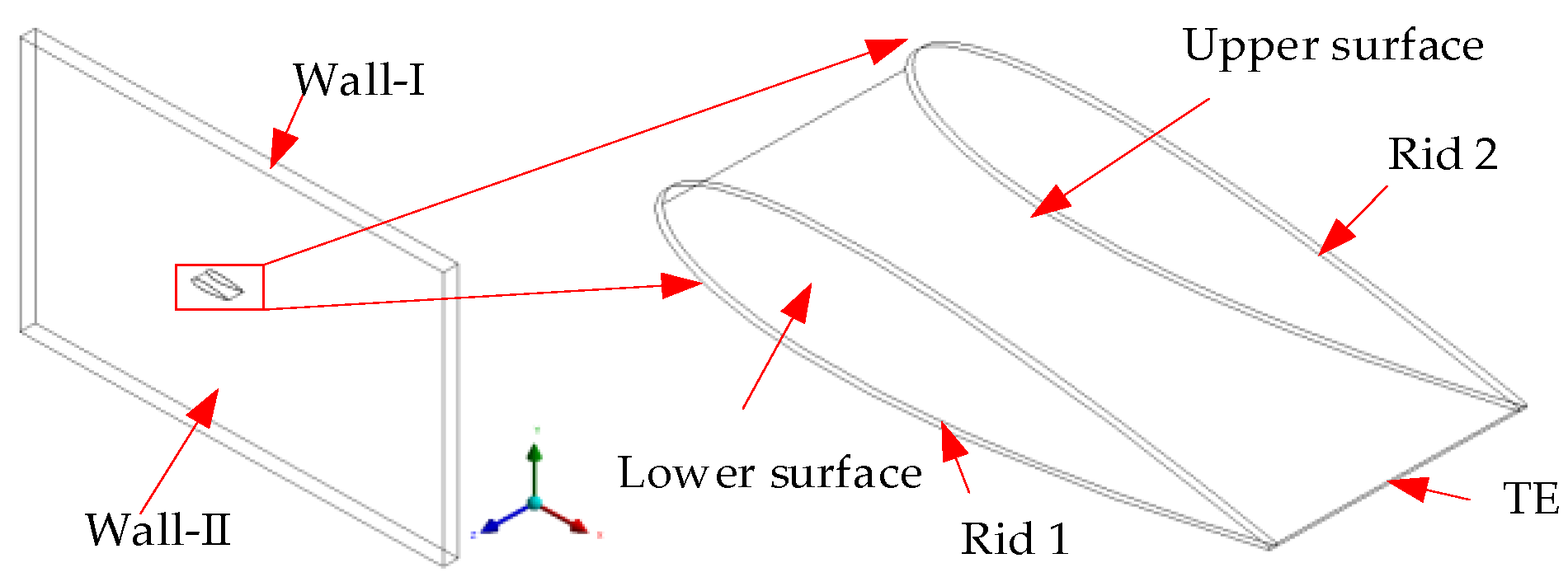
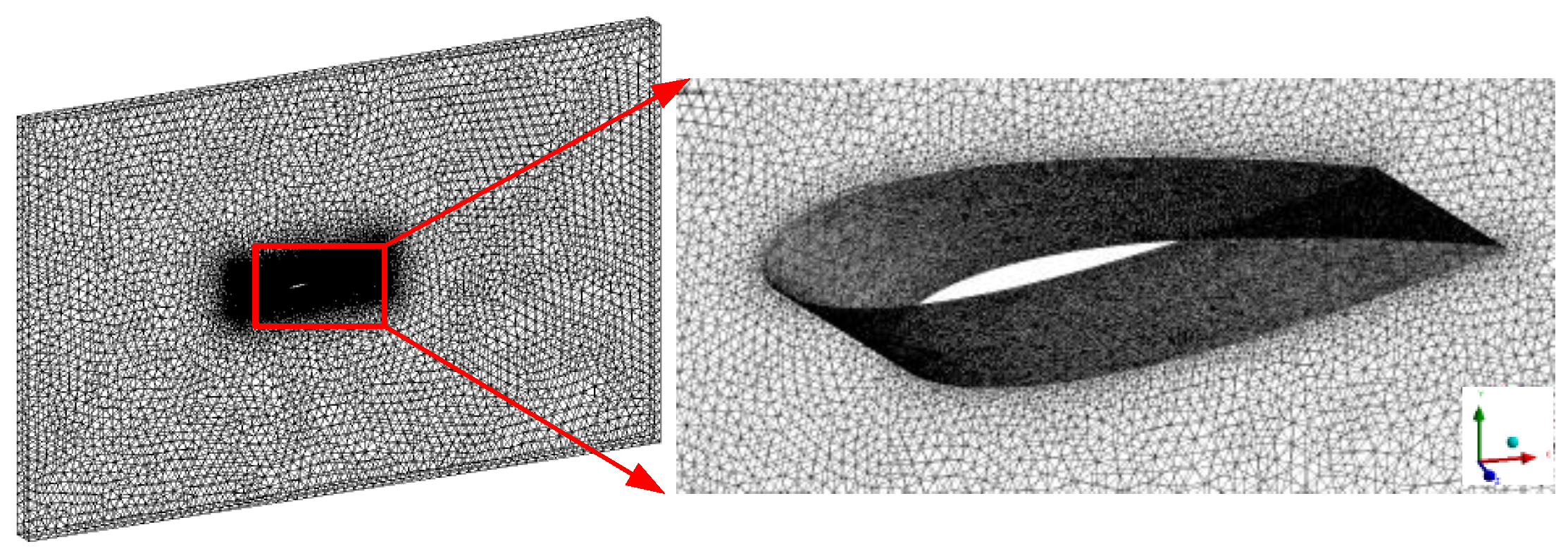
3.2.2. Morphing Wing CFD Fluid Model

The morphing wing structural model was created according to four different states, and then the morphing wing fluid model was created through the structural model. With reference to the coupling interface of the structural model, the morphing wing fluid wall surface was divided into five independent walls at the corresponding positions, namely the upper and lower skin, trailing edge and two ribs. The five independent walls are used for data transfer at the interface of fluid–structure coupling analysis. The wall perpendicular to the x- and y- axes is named Wall-I, whereas the wall perpendicular to the z- axis is named Wall-II, as shown in Figure 12. The chord length of the MWS mechanism is 850 mm and the length of a module wing along the wingspan is 358 mm. Based on the selected solver, the pressure far field boundary should be 20 times greater than the airfoil size. Therefore, the fluid size is 21,000 mm × 17,000 mm × 358 mm. An unstructured mesh technique with better geometrical adaptability and easy deformation was used for fluid meshing to achieve a large deformation of the fluid region near the airfoil. The fluid grid model of unstructured meshing was adopted, and the number of elements is 1.35 million, as shown in Figure 13.
The velocity boundary condition is set as the pressure far field: the Mach number is Ma = 0.6, the angle of attack is AOA = 6°, the reference pressure is Pr = 0 Pa, the gauge pressure is Pg = 70,100 Pa, the reference temperature is T = 268.65 K, and the flight environment at an altitude of 3 km is simulated, as shown in Figure 13. Finally, the dynamic two-way FSI simulation platform was built on the Ansys workbench.
The fluid model was imported into the Fluent fluid analysis software, and the fluid calculation conditions were set as follows: the gas model was selected as an ideal gas, the viscosity was set as the Sutherland viscosity, and the turbulence model was the k-w SST turbulence model. A density-based transient coupling solver was used, and the speed boundary condition was set as the pressure far field, with Ma = 0.6, Reynolds number of 6 × 10⁶, AOA = 6°, operating pressure of 0 Pa, gauge pressure of 70,100 Pa, and the reference temperature of T = 268.65 K, which is used to simulate a flight environment at an altitude of 3 km. The bidirectional fluid–structure coupling analysis requires the use of dynamic grid technology. The smooth mesh and reconstruction mesh technology of dynamic mesh in fluent software is used to realize the data transmission of the deformation and coupling interface of fluid mesh near the wing surface. The structural and fluid field of the initial state of the morphing wing is modeled. The morphing wing structure is influenced by the aerodynamic load mainly through the deformation and stress of the skeleton mechanism and the distribution of the flexible skin bucking. The change in drag coefficient and fluid mainly reflects the influence of structural deformation on morphing wing aerodynamic characteristics.

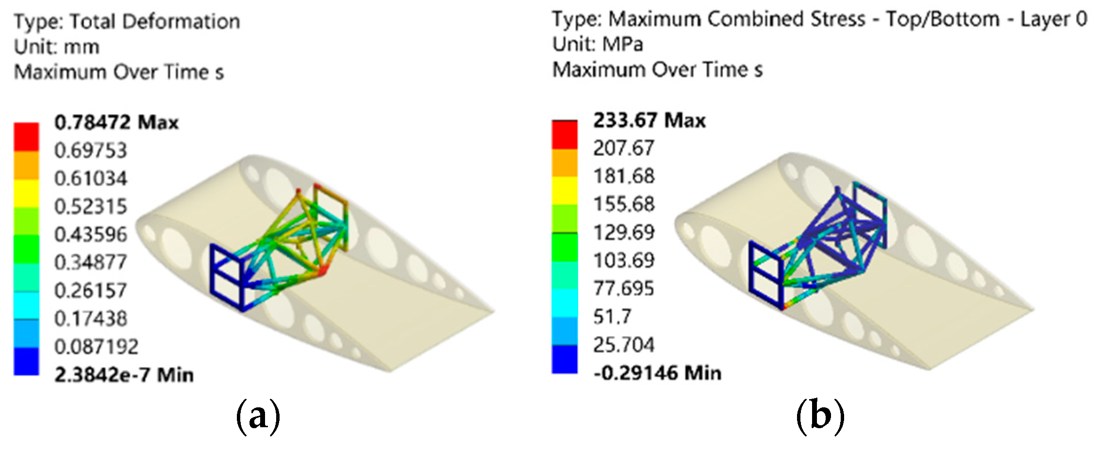
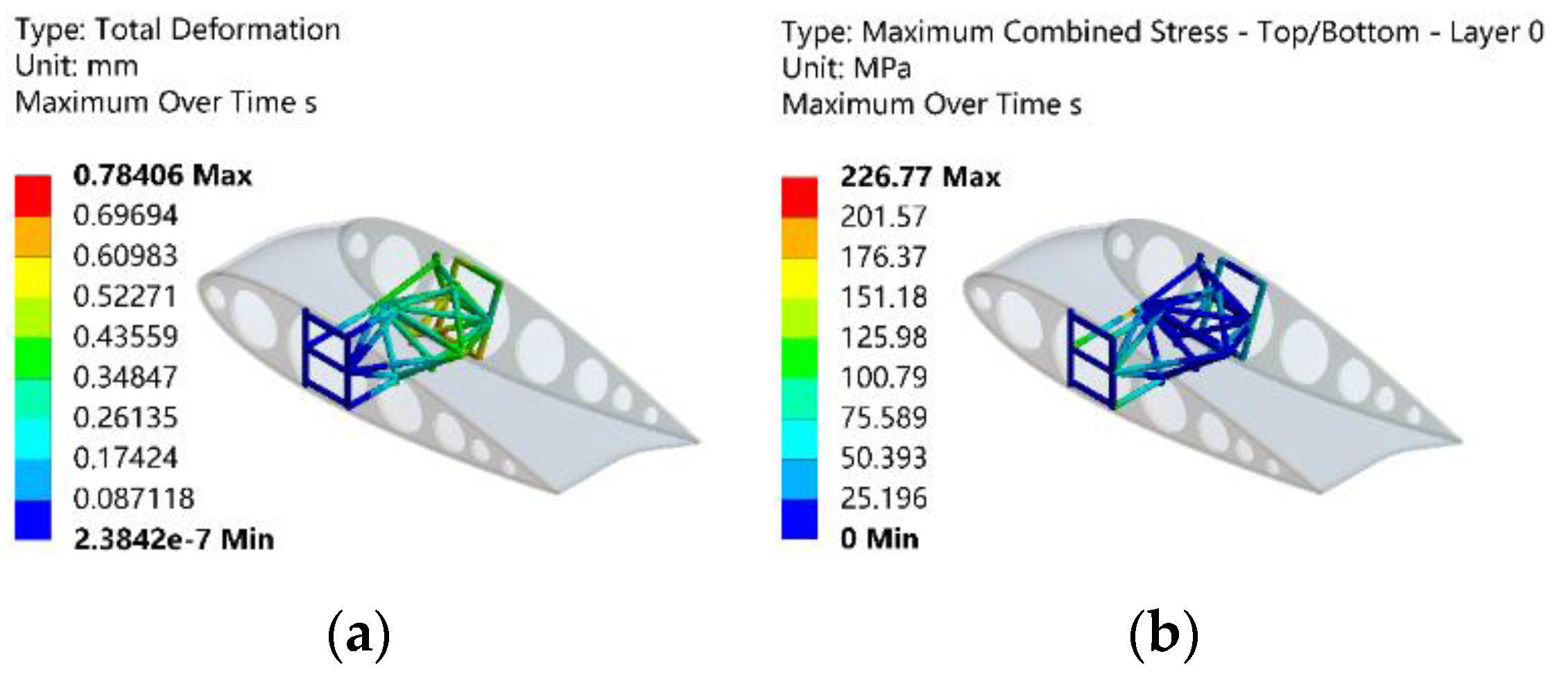
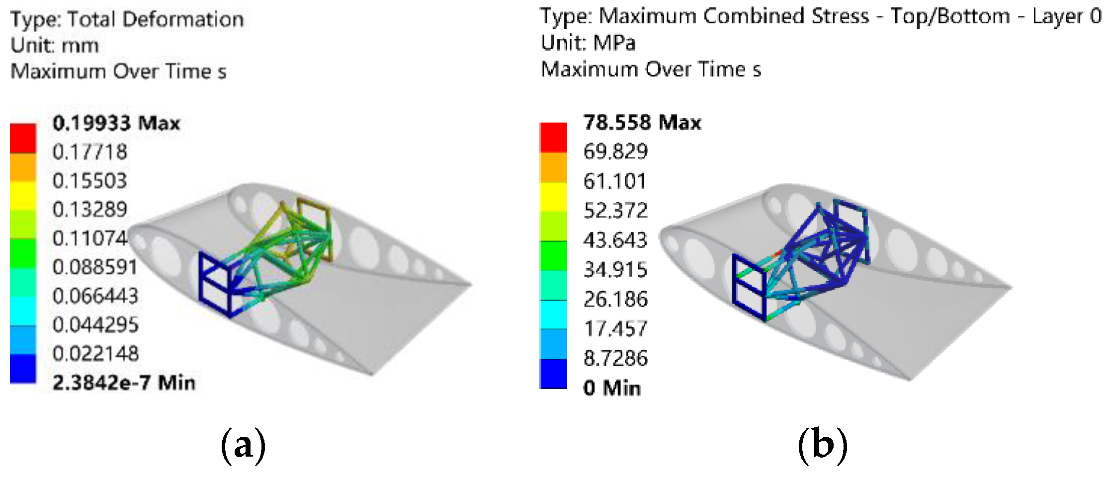
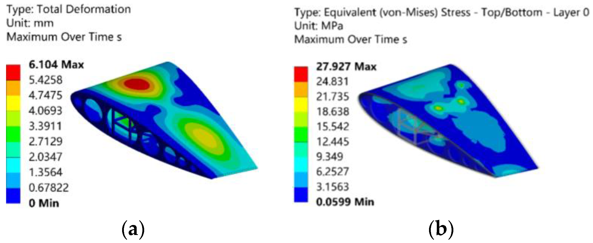
3.2.3. Discussion of Fluid–Structure Coupling Analysis

The deformation and stress distribution of the skeleton mechanism inside the morphing wing under aerodynamic load are depicted in Figure 14, Figure 15, Figure 16 and Figure 17. It is observed that the deformation in the four states is very small under the aerodynamic load, which indicates that the skeleton mechanism provides sufficient rigidity to withstand the aerodynamic load. Additionally, the maximum stress is below the yield strength of common metals (aluminum alloy 280 MPa and structural steel 250 MPa), demonstrating that the basic carbon fiber rod meets the strength requirements. Comparatively, the deformation in the initial state and the span-wise bend state is greater than that in the twisting and sweepback states, with a higher maximum stress in the former two deformation states. Therefore, the twisting and sweepback effectively reduce the aerodynamic force on the mechanism. Notably, the maximum stress of the skeleton mechanism is concentrated at the wing root and the output end of the swept-back actuator, providing an important reference for practical application and detailed designs.
The out-of-plane deformation and stress distribution of flexible skin in four deformation states under aerodynamic load are shown in Figure 18, Figure 19, Figure 20 and Figure 21. The yield strength of the metastructure flexible skin is the yield strength σs of the base material aluminum alloy, and it must be ensured that the simulation value σVonσ.
According to Figure 18, Figure 19, Figure 20 and Figure 21, the largest deformation of the flexible skin occurs in the initial state, followed by the swept, span-wise bent, and twisted states. In the initial and span-wise bending states, the deformation is mainly concentrated on the upper part of the trailing edge. Due to the negative pressure difference between the upper and lower wing surfaces, the flexible skin is sucked out of the bulge on the upper surface of the trailing edge. In the twisted state, the flexible skin is absorbed into a bulge near the leading edge, and the upper and lower airfoil surfaces near the trailing edge are depressed and compressed. This may be because the twisting deformation does not generate enough negative pressure areas on the upper and lower surfaces. For the flexible skin with sweepback deformation, the maximum deformation occurs on the upper surface near the leading edge, as the sweepback deformation increases the windward side of the leading edge and the aerodynamic load. The maximum stress experienced by the flexible skin in each deformation state is below the yield strength of the aluminum alloy, indicating that the skin will not be damaged. Based on the out-of-plane passive deformation criterion, which states that the out-of-plane deformation of the skin under aerodynamic load should be less than 0.5% of the chord length (δ = 850 × 0.5% = 4.25 mm), the load-bearing capacity of the flexible skin should be checked. Only the span-wise bending and twisting deformations meet the requirements for out-of-plane load capacity, as shown in Figure 19 and Figure 20. According to the distribution of the deformation, the out-of-plane deformation of the flexible skin can be reduced by improving the connection position between the flexible skin and the internal mechanism.
The lift and drag coefficients of the morphing wing before and after the passive deformation of the flexible skin are shown in Table 3, ΔCL and ΔCD indicate the extent of change in lift and drag coefficients, respectively.
Table 3 shows that the passive deformation of the flexible skin under the aerodynamic load has a certain impact on the aerodynamic characteristics of the morphing wing. Specifically, the skin deformation of the skin in the initial and span-wise bend states leads to an increase in the lift coefficient, and a decrease in the drag coefficient, ultimately resulting in an improved lift–drag ratio. This phenomenon is akin to the principle of variable airfoil thickness. The wing surface bulge is used to change the transition position of wing surface airflow from the laminar to turbulent flow to improve the quality of wing surface airflow and increase lift and reduce drag. The skin deformation in the twisting state reduces the lift and drag coefficients significantly owing to the small protrusion at the leading edge and the large depression at the trailing edge. The swept-back flexible skin has a small bulge at the trailing edge. However, the leading edge has a large bulge, and irregularly shaped wrinkles on the wing surface can induce a flow separation around the airfoil, resulting in a notable increase in the drag coefficient and the generation of more vortices.

4. Aerodynamic Characteristics of the Morphing Wing

The influence of three different deformed states and different flight environments on the aerodynamic characteristics of the morphing wing is studied. The definition of three different angles under three morphed states are shown in Figure 22.

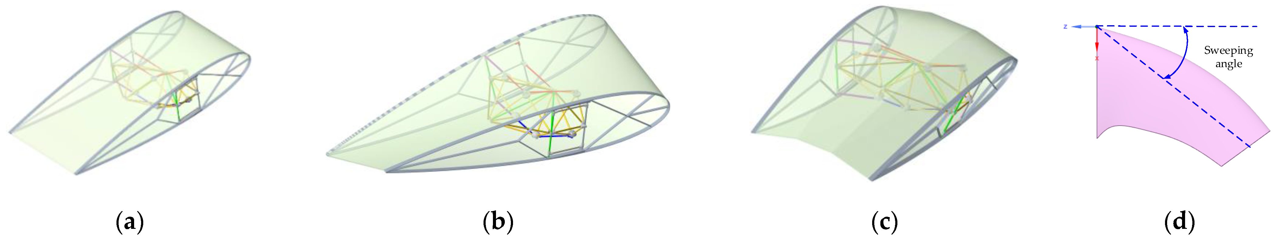
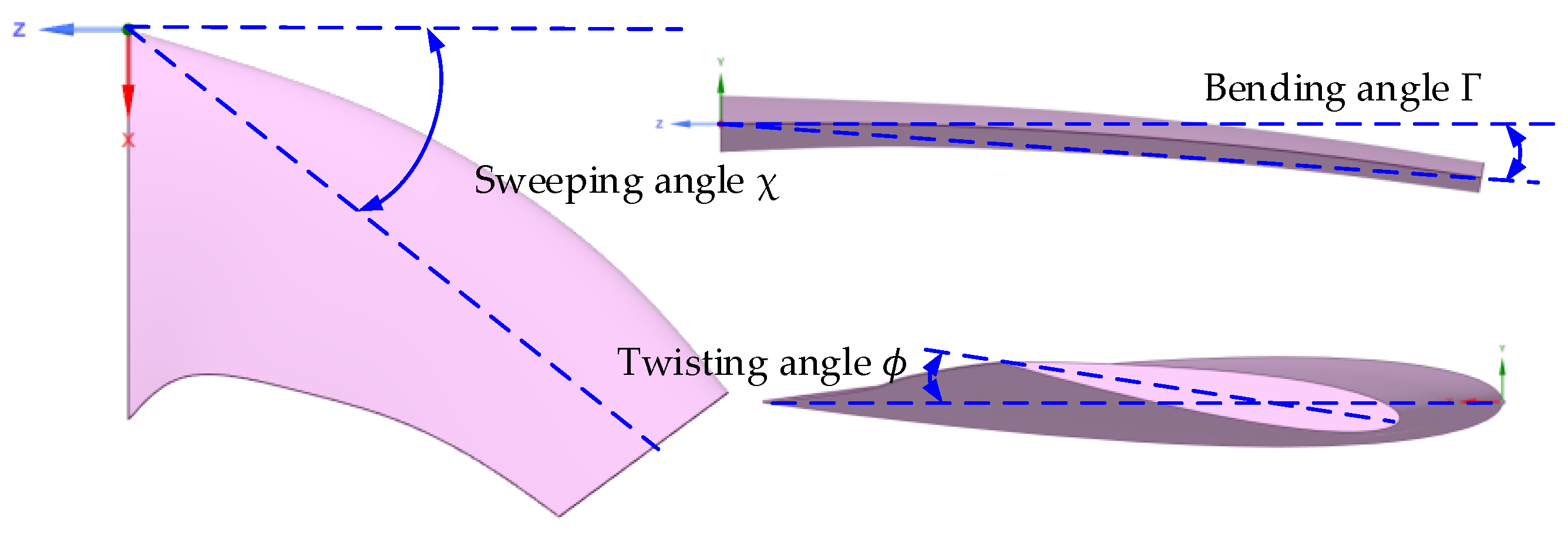
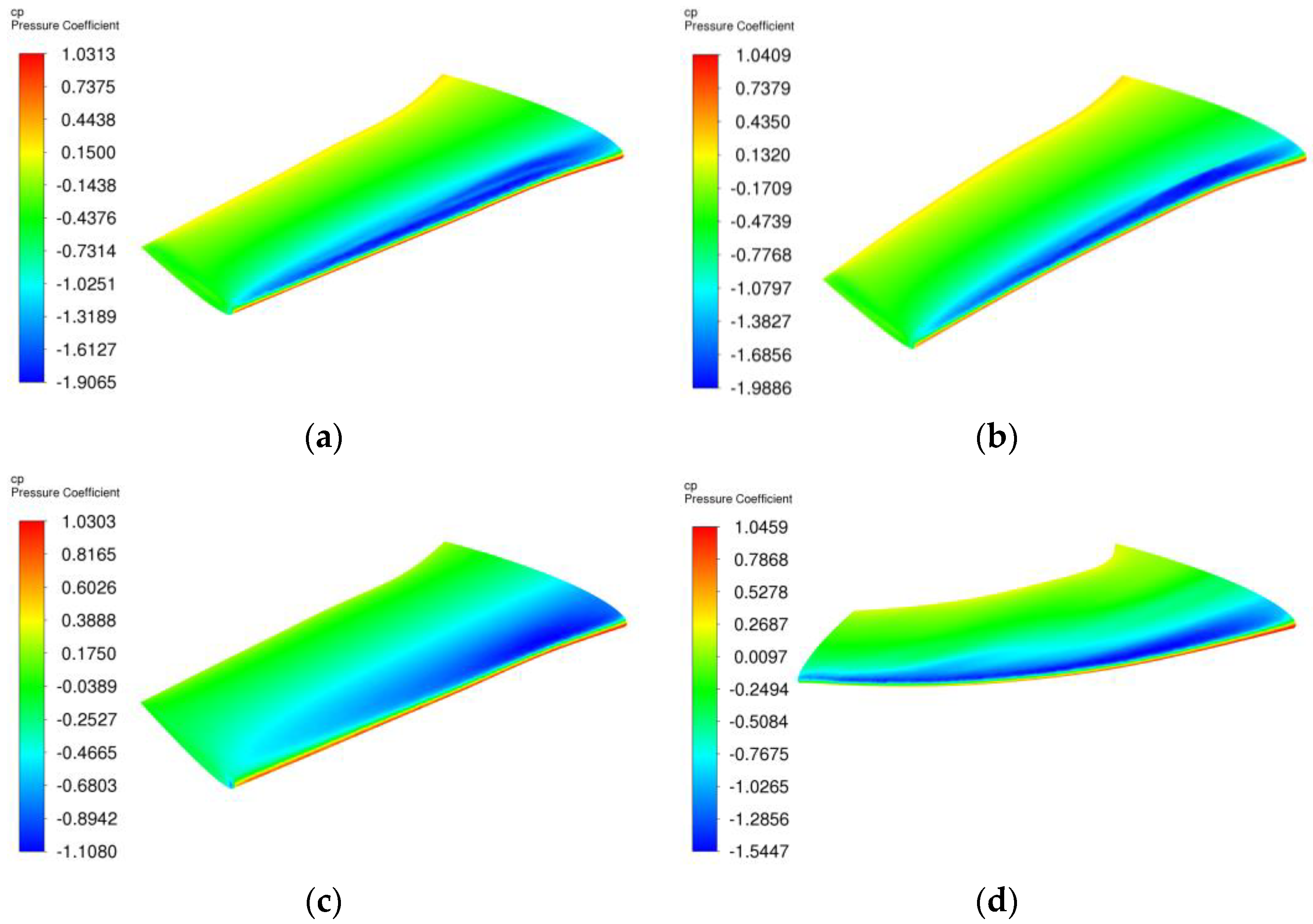
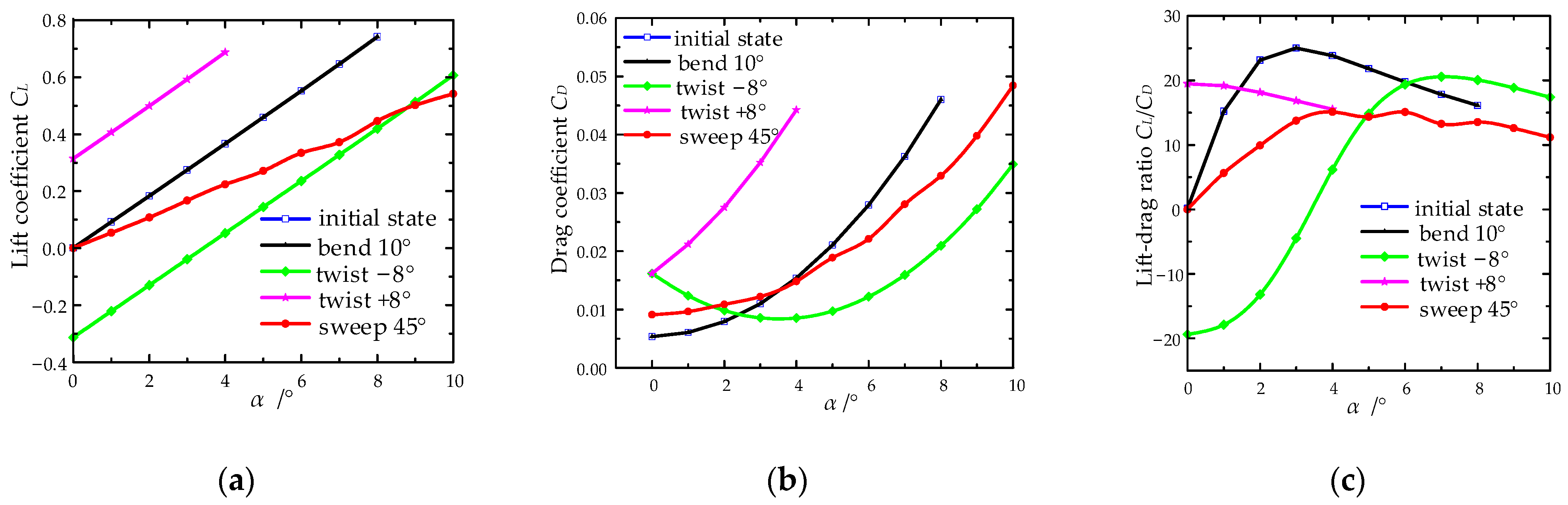
4.1. Influence of the Deformed State on Aerodynamic Characteristics

The numerical simulated state is as follows: the altitude is Ha = 3 km, the gauge pressure is Pg = 70,100 Pa, the temperature is t0 = 268.65 K, the flight speed is vf = 0.6 Ma, and the angle of attack is AOA = 6°. The influence of different deformed states on the airfoil pressure coefficient was studied. Airfoil pressure coefficients, at four kinds of different deformation states, are shown in Figure 23. It can be seen from Figure 23 that the pressure coefficient values and distribution of the initial state are similar to those of the wingspan bend state. Twist deformation makes the airfoil pressure coefficient move to the wing root and trailing edge. Moreover, the low-pressure area expands, but the negative pressure value and the lift coefficient decrease. The airfoil pressure coefficient distribution and initial state are the same, but the negative pressure value becomes smaller, which leads to a decrease in the lift coefficient.
In order to ensure the accuracy of the computational fluid dynamics analysis results, this article will take the initial shape of the morphing wing as a case to verify grid independence. There are three sets of grids with different scales: coarse grid (1.47 million), medium grid (3.43 million), and fine grid (6.42 million). The aerodynamic coefficients of morphing wing are evaluated under the above flight condition, as shown in Table 4. Here, ΔCL and ΔCD are the relative errors of aerodynamic coefficient calculated for the coarse and medium grids compared to the fine grid, respectively. It can be seen that the relative error of the lift and drag coefficients of each grid density is within the acceptable range, and the maximum error is the drag coefficient of coarse grid and fine grid, with a 1.89% difference. It indicates that we can obtain a convergent result, even deploying the coarse grid in terms of aerodynamic features.
The 3D aspect analysis software Xflr 5 v6.55 and Fluent 2022 R1 simulation software were used to conduct an aerodynamic analysis of the above four kinds of deformed state of the hybrid metastructure morphing wing. The aerodynamic characteristics of different deformation states are shown in Figure 24.
As shown in Figure 24, the lift coefficient, drag coefficient, and lift–drag ratio on the initial state and wingspan bend state increase gradually as the angle of attack increases. The regularity and magnitude of the curve are uniform, which means that wingspan bend deformation does not influence morphing wing aerodynamic characteristics, only the flight stability. When the morphing wing positive twist deformation occurs, the wing acquires a large angle of attack and obtains a greater lift coefficient, but it increases the drag coefficient. Thus, a positive twist is only used at a low speed and low elevation. On the contrary, a negative twist can reduce the drag coefficient and slow down the stall at a high angle of attack. The swept deformation reduces the drag coefficient and lift–drag ratio at a large angle of attack.

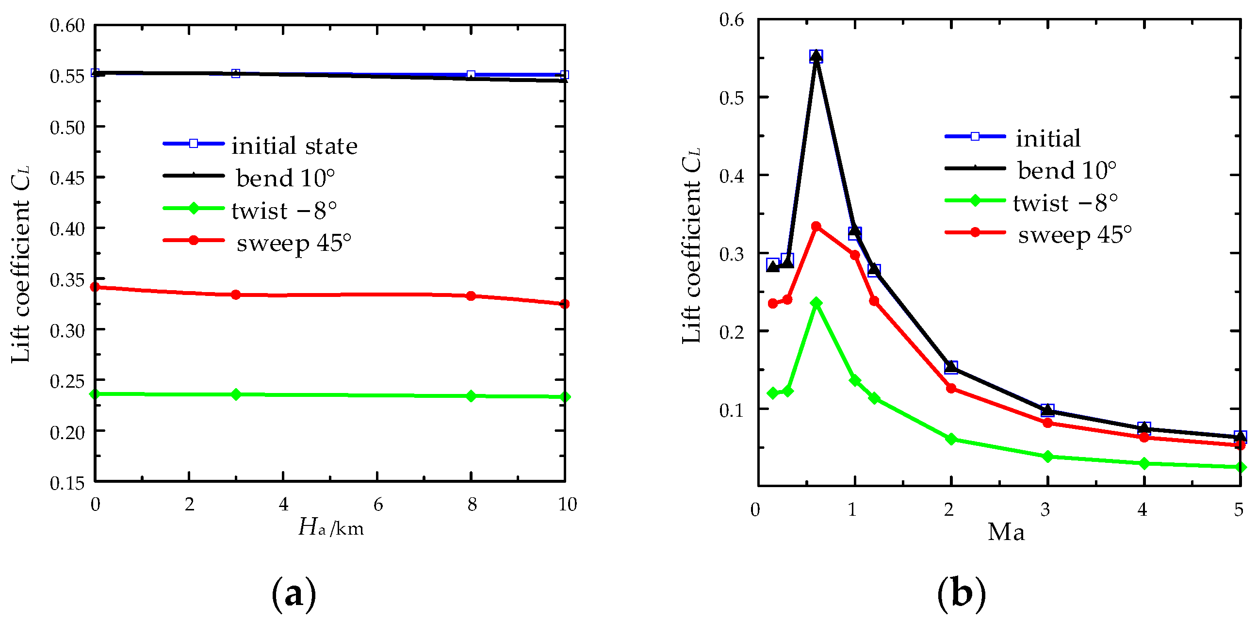
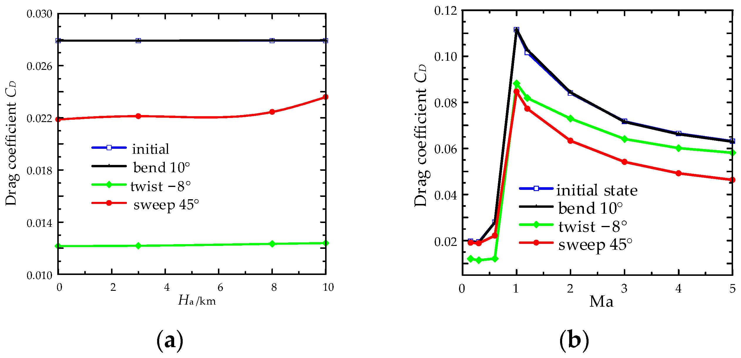
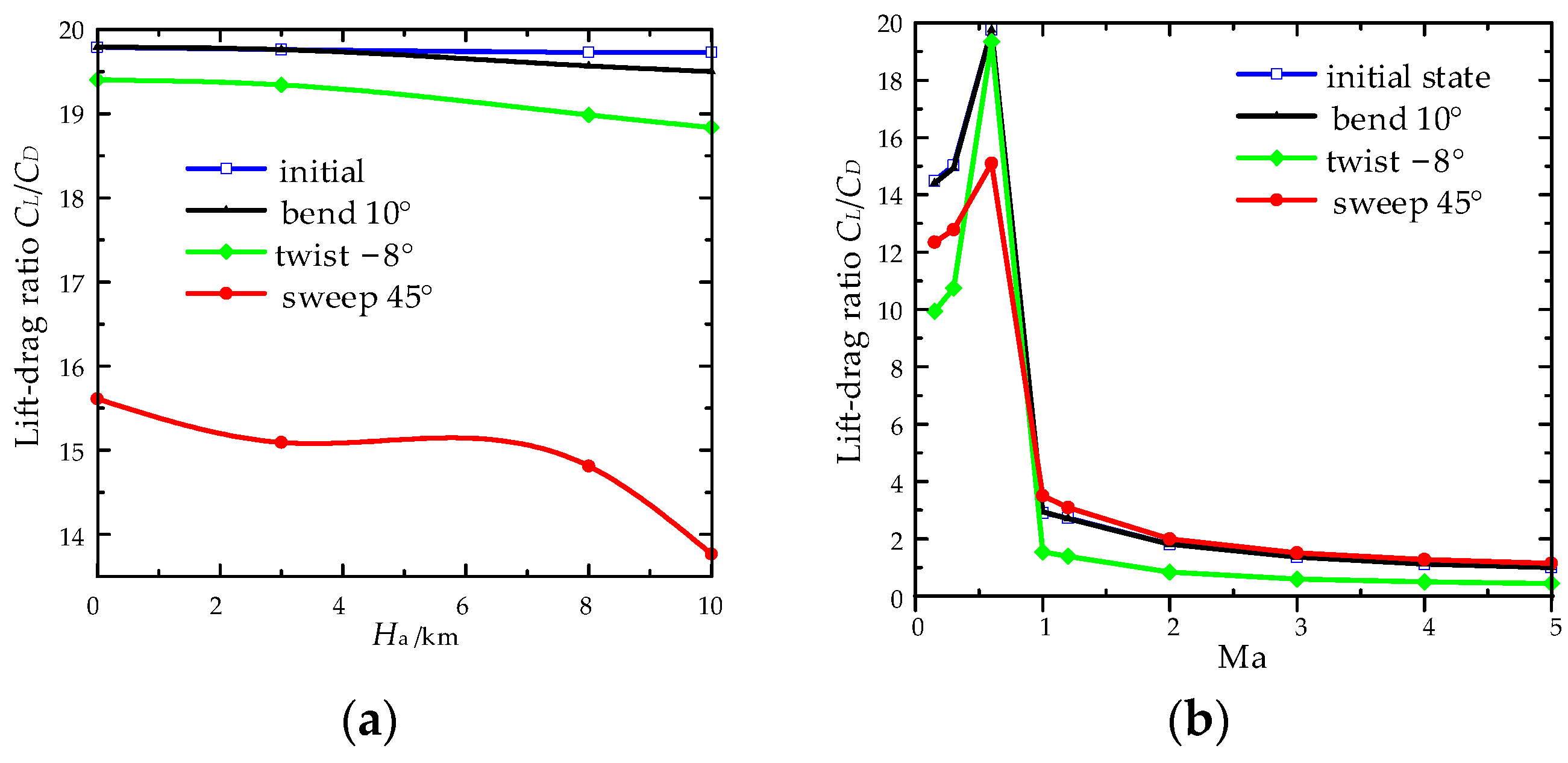
4.2. Effect of Flight Environment on Aerodynamic Characteristics

In the flight state, the speed is Ma = 0.6, and the angle of attack is AOA = 6°, and the influence of the altitudes of 0, 3, 8, and 10 km flight height on the morphing wing aerodynamic characteristics is shown in Figure 25a, Figure 26a and Figure 27a.
It can be seen from Figure 25a, Figure 26a and Figure 27a that the lift coefficients of each deformation state decrease to varying degrees with the increase in height, while the drag coefficients increase to varying degrees with the increase in height. Thus, the lift–drag ratios of initial, wingspan bending, twisting, and swept-back states decrease in varying degrees with increasing height. The swept state is most affected by the flight altitude.
Successively, subsonic velocity (0.15, 0.3, and 0.6) and supersonic velocity (1, 1.2, 2, 3, 4, and 5) are selected to compare the influence of flight speed on aerodynamic characteristics at the flight state of Ha = 3 km, and the angle of attack of AOA = 6°, as shown in Figure 25b, Figure 26b and Figure 27b. From Figure 25b, Figure 26b and Figure 27b, the aerodynamic characteristics under four different states of the hybrid metastructure morphing wing have the same variation rule with flight speed. Moreover, different deformed laws are presented in different speed stages. In the subsonic stage, the lift coefficient, drag coefficient, and lift–drag ratio gradually increase with the increase in speed. In the transonic and supersonic stages, the lift coefficient, drag coefficient, and lift–drag ratio gradually decrease with the increase in speed.

5. Conclusions

One MWS mechanism was proposed with modular BTP units, which had the capacities of continuous variable span-wise bend, span-wise twist, and sweep. A lockable morphing unit with the BTP unit was designed. One hybrid metastructure skin is proposed, which consists of the concave hexagon and the quadrangular star cell, and two flexible surfaces were bonded on both sides. Based on the theory of beam buckling, the theoretical models of the relative elastic modulus and Poisson’s ratio of the hybrid metastructure cell were established.
Fluid–structure coupling analysis on the MWS mechanism and flexible skin coupling model were carried out. The results demonstrated that the out-of-plane carrying capacity of flexible skin is mostly influenced by its initial and swept states. The wingspan bend and twist states of the flexible skin meet the deformation requirement, when the out-of-plane deformation should be less than 0.5%. Moreover, the out-of-plane bulge deformation in the flexible skin is advantageous in improving aerodynamic characteristics. Different deformed states, and the flight environment aerodynamic characteristics of the morphing wing, were analyzed. The results indicated that wingspan bend deformation has little influence on aerodynamic characteristics, while twist and swept deformations significantly alter aerodynamic characteristics. The flight height has little influence on aerodynamic characteristics, and lift–drag characteristics of each state increase with increasing speed in the subsonic stage. However, in the transonic and supersonic stages, lift–drag characteristics decrease with increasing speed.

Author Contributions

Conceptualization, H.Y.; methodology, S.J.; investigation, Y.W., software, H.X. All authors have read and agreed to the published version of the manuscript.

Funding

This research was funded by the National Natural Science Foundation of China (grant No. 52192631 and 51975001), and the APC was funded by the Science and Technology Project of the Hebei Education Department (grant No. QN2023206).

Data Availability Statement

Not applicable.

Conflicts of Interest

The authors declare no conflict of interest.

References

  1. Kammegne, M.J.T.; Botez, R.M.; Grigorie, L.T.; Mamou, M.; Mébarki, Y. Proportional fuzzy feed-forward architecture control validation by wind tunnel tests of a morphing wing. Chin. J. Aeronaut. 2017, 30, 561–576. [Google Scholar] [CrossRef]
  2. Fasel, U.; Keidel, D.; Baumann, L.; Cavolina, G.; Eichenhofer, M.; Ermanni, P. Composite additive manufacturing of morphing aerospace structures. Manuf. Lett. 2020, 23, 85–88. [Google Scholar] [CrossRef]
  3. Wang, J.; Zhao, Y.; Xi, F.; Tian, Y. Design and analysis of a configuration-based lengthwise morphing structure. Mech. Mach. Theory 2020, 147, 103767. [Google Scholar] [CrossRef]
  4. Xi, F.; Zhao, Y.; Wang, J.; Wang, W.; Tian, Y. Two actuation methods for a complete morphing system composed of a VGTM and a compliant parallel mechanism. J. Mech. Robot. Trans. ASME 2021, 13, 021020. [Google Scholar] [CrossRef]
  5. Yan, B.; Dai, P.; Liu, R.; Xing, M.; Liu, S. Adaptive super-twisting sliding mode control of variable sweep morphing aircraft. Aerosp. Sci. Technol. 2019, 92, 198–210. [Google Scholar] [CrossRef]
  6. Bowman, J.; Sanders, B.; Cannon, B.; Kudva, J.; Joshi, S.; Weisshaar, T. Development of next generation morphing aircraft structures. In Proceedings of the 48th AIAA/ASME/ASCE/AHS/ASC Structures, Structural Dynamics, and Materials Conference, Honolulu, HI, USA, 23–26 April 2007; p. 1730. [Google Scholar]
  7. Flanagan, J.; Strutzenberg, R.; Myers, R.; Rodrian, J. Development and flight testing of a morphing aircraft, the NextGen MFX-1. In Proceedings of the 48th AIAA/ASME/ASCE/AHS/ ASC Structures, Structural Dynamics, and Materials Conference; Honolulu, HI, USA, 23–26 April 2007, p. 1707.
  8. Jenett, B.; Calisch, S.; Cellucci, D.; Cramer, N.; Gershenfeld, N.; Swei, S.; Cheung, K.C. Digital morphing wing: Active wing shaping concept using composite lattice-based cellular structures. Soft Robot 2017, 4, 33–48. [Google Scholar] [CrossRef] [PubMed] [Green Version]
  9. Love, M.H.; Zink, P.S.; Stroud, R.L.; Bye, D.R.; Chase, C. Impact of actuation concepts on morphing aircraft structures. In Proceedings of the 45th AIAA/ASME/ASCE/AHS/ASC Structures, Structural Dynamics & Materials Conference; Palm Springs, CA, USA, 19–22 April 2004, p. 1724.
  10. Wang, Y.; Xiao, H.; Yang, G.; Jiang, H.; Liu, R.; Ding, J.; Guo, H. Structure design and distributed actuators configuration of a parallel linkage morphing wing. J. Harbin Inst. Technol. 2022, 54, 65–72. [Google Scholar]
  11. Liu, B.; Liang, H.; Han, Z.H.; Yang, G. Surrogate-based aerodynamic shape optimization of a morphing wing considering a wide Mach-number range. Aerosp. Sci. Technol. 2022, 124, 107557. [Google Scholar] [CrossRef]
  12. You, H.; Kim, S.; Joe, W.Y.; Yun, G.J. New concept for aircraft morphing wing skin: Design, modeling, and analysis. AIAA J. 2019, 57, 1786–1792. [Google Scholar] [CrossRef]
  13. Jones, M.P.; Murali, G.G.; Laurin, F.; Robinson, P.; Bismarck, A. Functional flexibility: The potential of morphing composites. Compos. Sci. Technol. 2022, 230, 109792. [Google Scholar] [CrossRef]
  14. Yu, J.R.; Ma, J.Y. Design and shear analysis of an angled morphing wing skin module. Appl. Sci. 2022, 12, 3092. [Google Scholar] [CrossRef]
  15. Yu, A.; Xi, F.F.; Moosavian, A.; Li, B. Design of a Sliding Morphing Skin with Segmented Rigid Panels. J. Aircr. 2018, 55, 1985–1994. [Google Scholar] [CrossRef]
  16. Moosavian, A.; Xi, F.F.; Hashemi, S.M. Design and motion control of fully variable morphing wings. J. Aircr. 2013, 50, 1189–1201. [Google Scholar] [CrossRef]
  17. Yokozeki, T.; Takeda, S.-I.; Ogasawara, T.; Ishikawa, T. Mechanical properties of corrugated composites for candidate materials of flexible wing structures. Compos. Part A Appl. Sci. Manuf. 2006, 37, 1578–1586. [Google Scholar] [CrossRef]
  18. Wang, Z. Recent advances in novel metallic honeycomb structure. Compos. Part B Eng. 2019, 166, 731–741. [Google Scholar] [CrossRef]
  19. Majid, T.; Jo, B.W.; Cestino, E. Status and challenges on design and implementation of camber morphing mechanisms. Int. J. Aerospace Eng. 2021, 2021, 6399937. [Google Scholar] [CrossRef]
  20. Wang, J.; Li, Z.; Liang, F.; Liu, W.; Liao, J.; Chen, F.; Li, M.; Shao, T. Design, simulation and theoretical study on novel cored octagon honeycomb for helicopter crashworthiness. Acta Aeronaut. Astronaut. Sin. 2022, 43, 225244. [Google Scholar]
  21. Olympio, K.R.; Gandhi, F. Zero Poisson’s ratio cellular honeycombs for flex skins undergoing one-dimensional morphing. J. Intell. Mater. Syst. Struct. 2010, 21, 1737–1753. [Google Scholar] [CrossRef]
  22. Bubert, E.A.; Woods, B.K.S.; Lee, K.; Kothera, C.S.; Wereley, N.M. Design and fabrication of a passive 1d morphing aircraft skin. J. Intell. Mater. Syst. Struct. 2010, 21, 1699–1717. [Google Scholar] [CrossRef]
Figure 1. Composition of the lockable morphing unit: (a) the BTP unit, (b) 1/2 BTP unit, and (c) the LM unit.
Aerospace 10 00678 g001
Figure 2. Morphing schematic diagram of the LM unit: (a) initial state, (b) sweep, (c) twist, and (d) span-wise bend.
Aerospace 10 00678 g002
Figure 3. Composition of the MWS mechanism. The numbers in the figure represent the linear actuators number, while the letters represent the lockable passive member number.
Aerospace 10 00678 g003
Figure 4. Diagram of hybrid metastructure flexible skin.
Aerospace 10 00678 g004
Figure 5. Hybrid metastructure and its geometrical parameters: (a) m × n hybrid metastructure and (b) geometrical parameters.
Aerospace 10 00678 g005
Figure 6. Equivalent stiffness of hybrid metastructure cell: (a) x direction loading, (b) x direction equivalent series spring, (c) y direction loading, and (d) y direction equivalent parallel spring.
Aerospace 10 00678 g006
Figure 7. The morphing wing with metastructure skin.
Aerospace 10 00678 g007
Figure 8. Four deformation states of single-module skeleton mechanism and skin: (a) initial state, (b) twist, (c) span-wise bend, and (d) sweep.
Aerospace 10 00678 g008
Figure 9. Flowchart for the numerical simulation of two-way FSI.
Aerospace 10 00678 g009
Figure 10. FEM model of the morphing wing in initial state.
Aerospace 10 00678 g010
Figure 11. Three FEM mesh models in deformation state: (a) wingspan bend, (b) twist, and (c) swept.
Aerospace 10 00678 g011
Figure 12. Flow field boundary naming.
Aerospace 10 00678 g012
Figure 13. Grid model of morphing wing flow field.
Aerospace 10 00678 g013
Figure 14. Deformation and stress distribution of skeleton mechanism in initial state: (a) initial deformation and (b) initial stress.
Aerospace 10 00678 g014
Figure 15. Deformation and stress distribution of skeleton mechanism in bending state: (a) bending deformation and (b) bending stress.
Aerospace 10 00678 g015
Figure 16. Deformation and stress distribution of skeleton mechanism in twisting state: (a) twisting deformation and (b) twisting stress.
Aerospace 10 00678 g016
Figure 17. Deformation and stress distribution of skeleton mechanism in sweeping state: (a) sweeping deformation and (b) sweeping stress.
Aerospace 10 00678 g017
Figure 18. Deformation and stress distribution of flexible skin in initial state: (a) deformation and (b) stress.
Aerospace 10 00678 g018
Figure 19. Deformation and stress distribution of flexible skin in bending state: (a) deformation and (b) stress.
Aerospace 10 00678 g019
Figure 20. Deformation and stress distribution of flexible skin in twisting state: (a) deformation and (b) stress.
Aerospace 10 00678 g020
Figure 21. Deformation and stress distribution of flexible skin in sweeping state: (a) deformation and (b) stress.
Aerospace 10 00678 g021
Figure 22. The definition of three different angles under three morphed states.
Aerospace 10 00678 g022
Figure 23. Airfoil pressure coefficient at different deformation states (AOA = 6°): (a) initial state, (b) wingspan bend 10°, (c) twist angle –8°, and (d) swept angle 45°.
Aerospace 10 00678 g023
Figure 24. Aerodynamic characteristics of different deformation states: (a) lift coefficient, (b) drag coefficient, and (c) lift–drag ratio.
Aerospace 10 00678 g024
Figure 25. Lift coefficient at different altitudes and velocities: (a) different height and (b) different speed.
Aerospace 10 00678 g025
Figure 26. Drag coefficient at different altitudes and speeds: (a) different height and (b) different speed.
Aerospace 10 00678 g026
Figure 27. Lift–drag ratio at different altitudes and speeds: (a) different height and (b) different speed.
Aerospace 10 00678 g027
Table 1. Maximum deflection under homogeneously distributed load.
Simulated Results wmax/mmTheoretical Result wmax/mmRelative Error RE/%
The hybrid metastructure skin0.843950.7946−5.8575
The equivalent orthogonal anisotropic sheet0.82234−3.3732
Table 2. Material properties of carbon fiber (395 GPa).
Density (g/cm3)Young’s Modulus (MPa)Poisson’s Ratio
ExEyEzvxyvyzvxz
Carbon fiber1.8395,000600060000.20.40.2
Table 3. Influence of flexible skin on lift–drag characteristics of morphing wing.
StateCLΔCL/%CDΔCD/%
Rigid SkinFlexible SkinRigid SkinFlexible Skin
Initial0.55850.592366.060.0302100.026716−11.57
Bend0.17320.178352.970.0286480.026825−6.36
Twist0.05550.05407−2.580.0192760.014484−24.86
Sweep0.117670.117760.0760.0188810.02181815.6
Table 4. Grid independence study of aerodynamic coefficient for morphing wing.
Grid SizeCLΔCL/%CDΔCD/%L/D
Coarse (1.47 million)0.397680.180.0210031.8918.93448
Medium (3.43 million)0.39307−0.990.020292−1.5619.37043
Fine (6.42 million)0.396980.02061419.25771
Disclaimer/Publisher’s Note: The statements, opinions and data contained in all publications are solely those of the individual author(s) and contributor(s) and not of MDPI and/or the editor(s). MDPI and/or the editor(s) disclaim responsibility for any injury to people or property resulting from any ideas, methods, instructions or products referred to in the content.

