1. Introduction
One of the issues that requires extensive knowledge from many fields is the design of aerospace structures. That process requires meeting criteria from many different disciplines [
1,
2], namely, aerodynamics, material strength, production technology, materials science, aviation law, and finally, general aviation knowledge, which cannot be described with simple relationships. This complexity means that there is no established procedure for the initial design and construction of an aircraft, and thus, the optimal solution is achieved using iterative matching of parameters [
3,
4]. This is an extremely time-consuming process that requires a lot of work. Interpreting the calculation results is only a small part of this process. At the same time, confrontation of effects with design assumptions is required.
In the design activities of aircraft, flexibility is also very important, for example, in geometric models, whose development involves constant changes in their structure. Thus, in the case of conventional methods, these changes would necessitate a large amount of work with each one-time change, and in the case of conventional methods, it would be necessary to involve many specialised engineers from various areas responsible for the project. In the case of the alternative, which is engineered using a knowledge base, we deal with a knowledge base that largely replaces the need for each intervention of specialists and streamlines many processes and activities performed for the concept being developed. A specific example is parametric models or generative models, which are direct solutions derived from knowledge-based engineering tools, which, in turn, help to create models in the CAD (computer-aided design) environment. Their geometric parameters and the design rules describing them are supported by a previously created knowledge base, the record of which is based on the general principles of building such structures, specialist knowledge, and previous experience and drawn from the basis of conclusions. Thanks to this, working with such models allows even less experienced users to create or modify them because the most important processes and compliance with the necessary rules are carried out using algorithms and formulas referring to a database, and at the same time, many of these activities are simplified and their finalisation takes much less time.
2. Materials and Methods
Although design automation methods have been used for a long time, systems that automate the design process—knowledge-based engineering (KBE)—are still not widely used, and if they are used, it is usually in the case of repetitive and labour-intensive development work [
5]. Usually, such a system is not designed ad hoc, but is one of the elements of the system engineering (SE) approach [
6], allowing a systemic approach to product development processes and a modern approach to work organisation with the application of the concurrent engineering (CE) [
7] idea.
The exchange of information and its organisation has become the key problem that aviation manufacturers are working on. For this purpose, XML (Extensible Markup Language) technology [
8], known for years, is used. Open formats and description schemes, such as the Common Parametric Aircraft Configuration Schema (CPACS) [
9], are intended to serve as the data definition for the air transportation system. CPACS enables engineers to exchange information between their tools. It is therefore a driver for multidisciplinary and multifidelity design in distributed environments. CPACS describes the characteristics of aircraft, rotorcraft, engines, climate impact, fleets, and missions in a structured, hierarchical manner. Not only the product but also the process information is stored in CPACS. Another example of using the model-based system engineering (MBSE) approach is the AGILE 4.0 project, which also builds ontologies that organise information resources in the aviation field [
10,
11]. The recipients of these systems are large aviation companies that achieve particular benefits because of the need to exchange information with their co-operators.
The use of descriptive languages has its roots in the methodology used to build KBE systems, such as MOKA (methodology for knowledge-based engineering applications) [
12] or KNOMAD [
13], which describe metamodels used in the development of complex technical systems. Metamodels allow us to define the structure of the knowledge base that is used in KBE systems based on these methodologies. Such a broad approach has its drawbacks. By ensuring multidisciplinary cooperation, the possibility of identifying relationships between domains at lower levels of information processes and structures is lost. In the case of model-based design (MBD) and generative modelling (GE), there is a possibility for the transdisciplinary building of information structures and building deeper transdisciplinary relations.
The generative model is a specific type of virtual model developed in the CAx (computer-aided x) class environment. CAx can automatically generate virtual models or draw documentation of the designed technical object at the end of the process using integrated knowledge of the designed design feature, element, or set of elements and predefined input information, no matter if it is geometric or parametric. This is accomplished using the existing automation techniques in the CAx environment [
14].
In the classic design process using the CAD system, the designer creates a model of the object based on his/her own knowledge or knowledge derived from external sources such as standards, catalogues, etc. In the case of creating a generative model, the role of the designer is completely different [
14]. In this case, the designer, together with the knowledge engineer, tries to identify the appropriate geometric features of the object and develops a set of parameters and rules that describe the given features [
13,
14]. The result of these activities is a CAD model that allows the automatic generation of specific design features based on the assumed input data. This approach is justified, especially in smaller enterprises, due to the integration of models directly in the CAx tool.
An example of another systemic approach is the use of SySML (Systems Modelling Language) [
15,
16] to record the architecture of the modelled system. Easy integration with CAD systems allows for processing of the system, which, in this way, is saved not only to the CAD model [
17] but also to further process these data in MBD (model-based design) systems [
18], or the TSM (total system modelling) approach, in a systematic way. The use of data recording formalisation such as XML (eXtensible Modelling Language) [
8], SysML [
15], UML (Unified Modelling Language) [
19], and OWL (Web Ontology Language) [
20] allows for a systematic and ordered approach; however, it requires defining one’s own formal data structures describing the space of a given domain. This is a laborious, multiyear task. When developing generative models in smaller enterprises, these steps can be skipped, and formal saving of the data space may take place using tools that support parametric recording directly in the CAD system.
The development of such a system requires laborious preparation covering various stages of the process but not as much as in the systematic approach. In this study, our development team used experience from knowledge acquisition, and also the creation of generative models [
14] used in this case, as a guiding element for the design automation system in the development of the current system that is presented. Particular attention was paid to the systematic and structural approach for constructing generative models, emphasising the structure of the model and the data related to the models and providing great flexibility in the application of the models and their reusability. This allows for easy integration not only with the analytical methods for design verification presented in this article but also with the high-fidelity simulation methods commonly used in design based on finite element methods (FEMs), together with more systematic design methods such as model-based design [
21], developed in aircraft design [
22], as well as unmanned aerial vehicles (UAVs) [
22,
23].
The main tasks to be carried out in the creation of such software are:
Development of a user interface with a database supporting analytical calculations for the verification of selected aircraft design features.
Development of a tool for fast and accurate recalculation of parameters in concept aircraft models with an appropriate interface.
Development of a set of procedures with a user interface allowing for verification of structural features.
Integration of design verification methods used in aircraft design with methods for determining structural features in developed generative models.
Integration of the database with the interface using the generative model in the CAD environment.
Performing calculations to check the correct operation of such software for selected cases of designed aircraft.
In addition, it was assumed that the environment in which all work would be carried out was MS Excel, for creating a knowledge base with a user interface, and ultimately, the Siemens NX CAD environment for defining and generating 3D models.
This choice was made primarily based on the availability of student licences that allow full use of the resources in these programmes without the need to purchase a licence for software development. In addition, the MS Excel environment is by definition an ideal environment for complementing and systematising all data that make up the knowledge base due to the clear interface and available programme functions. In the case of using the NX Siemens environment, the main justification was the availability of functions for creating surface and solid models and the method for creating geometry using curves based on many points. Using this environment, our work was completed in a very good and error-free way, which, using other CAD environments, was sometimes problematic and often required additional operations or other solutions to obtain satisfactory results.
The main objective of the work in this study was to create generative models allowing a user to obtain a complete geometric model for a given class of aircraft with the possibility of indicating the appropriate geometry and parameter values forming the entire structure, using an appropriate interface based on an appropriately stored database.
Among the available literature and materials, you can often find solutions in the field of creating models of aircraft structures along with simulations, especially in the context of MDO (multidisciplinary design optimisation) [
24], e.g., in the field of CFD (computational fluid dynamics) flow analysis (usually on surface models) used for aerodynamic analyses of aircraft, including simulation of airflow around the wings, fuselage, propulsion, and other aircraft assemblies. This allows engineers to determine the effect of different configurations and shapes on the aircraft’s aerodynamic characteristics and solve problems related to aerodynamic stall and noise generation. In the case of the project in question, in addition to generating ready-made hybrid models (using surface and solid modelling) of given structures, the software allows for a preliminary strength analysis of the entire volume of the designed structures using analytical calculations, which are formulated based on the literature on aircraft design methods. The data and formulas are collected in a spreadsheet that serves as a knowledge base on which all calculations are based. Thus, the software allows for the direct generation of precalculated CAD models of aircraft, not only models created for CFD analysis, which, in the end, must usually be properly prepared for testing after the modelling stage, as described in the available sources.
When formulating the assumptions of this study, one of the established issues was defining a small range of aircraft domains to create a compact, but complete, solution. It was clear that a specific class of aircraft had to be chosen, for which all calculations would be carried out, and that a set of knowledge had to be chosen. Thus, gliders became the target class of aircraft. Due to the simplicity of their structure, they are characterised by a reduced number of more complex analytical calculations and a reduced number of components, for which a set of knowledge was needed to achieve results without initial complexity. Among such problematic assemblies, a propulsion system was mentioned, which is not standard in this type of aircraft construction.
Based on calculations widely described in the literature [
25], spreadsheets were created to calculate glider parameters for use in the generative model. These included separate parts concerning glider geometry, strength parameters, flight parameters, and other parameters. The geometry section provided a list of linear and angular dimensions necessary to complete the shape of a glider, along with basic data on the internal structure.
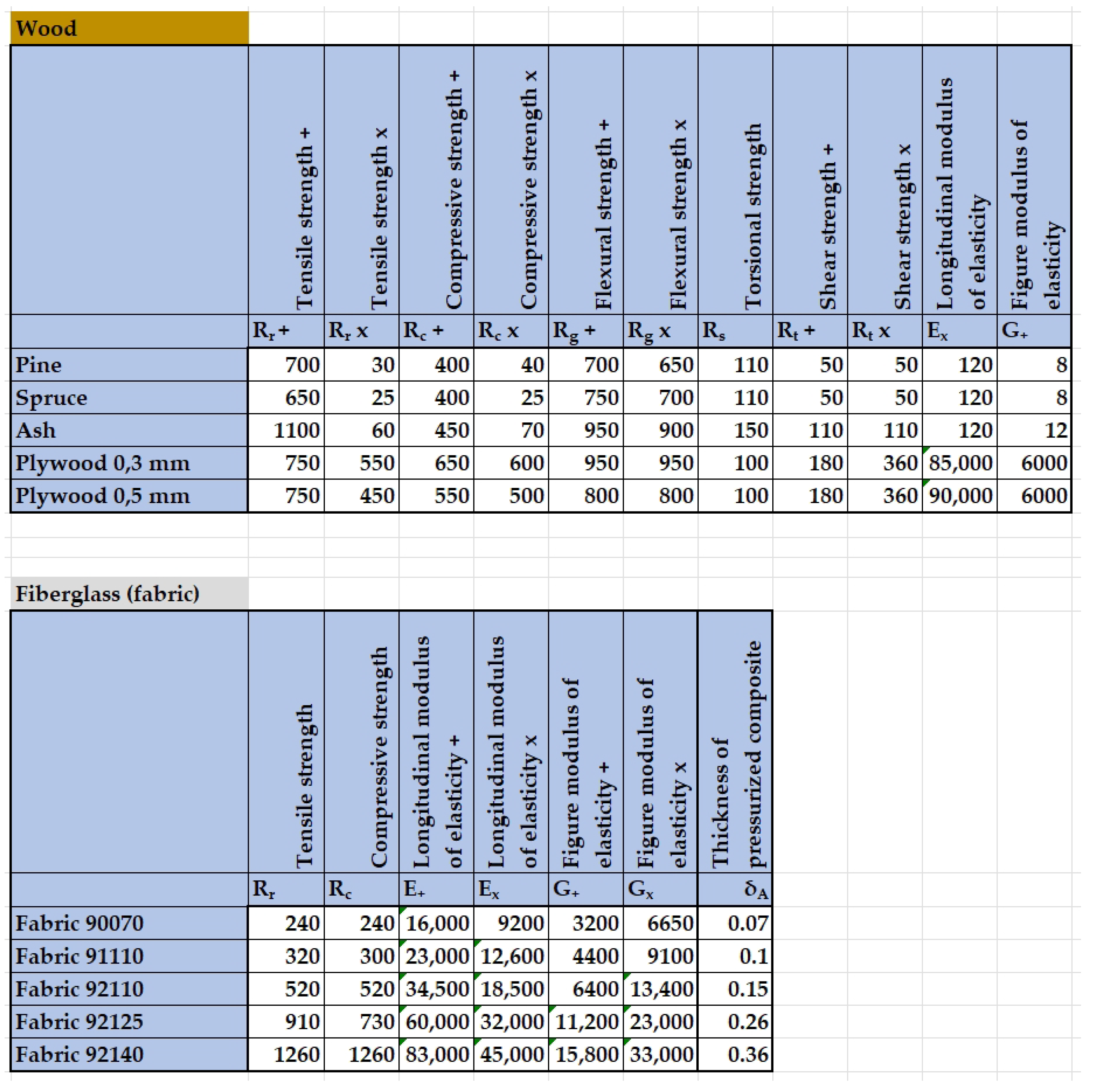
The described knowledge base, which is the foundation for the software, mainly covers the methodology for calculating and designing aviation structures (mainly gliders), but it also contains additional information on engineering materials used in aviation along with their most important characteristics, including wood and its most important types and selected metals and their alloys and composites. The content of the material database enables its scope to be extended along with the further development of the entire software. All information and values for material properties were obtained from the literature [
4], which facilitated the creation of the entire knowledge base for the needs of the described software.
An important issue when creating generative models based on parameters calculated using external programmes is the method for data exchange. It must meet the assumption of automatic data updates so that the parameters imported into the model match the parameters calculated in the programme. In the case of the integration of MS Excel spreadsheets and Siemens NX models, this means choosing specific tools and not using CAD software functions that do not meet this condition. The use of parameter selection within Siemens NX using the PTS Author interface creation tool was considered, but this possibility was rejected due to the difficulty of exporting and updating parameters from the model in Siemens NX attributes to worksheets without using Visual Basic code.
Ultimately, it was decided that the optimal solution was to completely separate the functions in the spreadsheets and the model, i.e., the spreadsheets would be used for preparing the relevant data, including validation, interface, and the calculation of dependent parameters, and the model in NX would only be a graphical representation of these data. Interference with the model was only possible by changing the parameters in the sheets. This ensured that the data were always consistent and, thus, there was no need to compare the Siemens NX data with the data in the Excel spreadsheets.
The chosen approach implies certain requirements for data exchange. The NX function is characterised by the fact that when you change parameters in an xlsx file, you must save the workbook and then refresh the external connections in Siemens NX (Tools > Expressions > Update for External Change tab). In the NX version, it is not possible to automate this activity easily.
Parameters from a spreadsheet are read using the functions available in NX: ug_excel_read, ug_cell_read, and ug_read_list. Some parameter definitions are not identical in the sheets and the CAD model; therefore, some of them are recalculated using the NX ‘expressions’ module. This is especially true for the shape of the profile, which is entered using equations, as opposed to the shape estimated in the spreadsheet using a set of points.
Simplifications in the initial modelling mean that certain elements, in particular, the control surfaces, may overlap when checking the range of motion after generating models. This is due to the philosophy of creating a model, where each of the elements is created separately, without considering the influence of shapes of other elements.
In the current version of the software, the NACA (National Advisory Committee for Aeronautics) [
26] 4-digit profile generator is based on equations that define the profile shape. From the name entered in the table, individual digits corresponding to the profile parameters are read, and on this basis, the appropriate coefficients are entered into the equations.
The assembly file that is the output model contains the following part files:
For each element, there is an appropriate module for geometry creation, aerodynamic parameter calculation, strength verification, and CAD-dependent geometrical parameter calculation.
In addition to these elements, the assembly in the CAD environment contains mirrored parts of the wing, aileron, flap, half-horizontal stabiliser, and elevator. All these elements are connected with two types of connections: hinge type and anchor type. The hinge connections are applicable to all control surfaces. For each such connection, an axis of rotation and a point of contact should be defined. The remaining constraints are based on local coordinate systems. Each model is built in such a way that its position is calculated relatively to the point located on the extension of the leading edge of the wing on the longitudinal axis of an airframe. The constraints of individual elements connect the corresponding planes in the coordinate systems.
The coordinate system used in the calculation is fundamentally different from the coordinate system used in the CAD model. In Excel sheets, geometries are considered in a two-dimensional coordinate system on section planes. The x-axis is the longitudinal axis of an airframe, while the y-axis is the axis perpendicular to the x-axis lying on the plane of a currently considered cross-section.
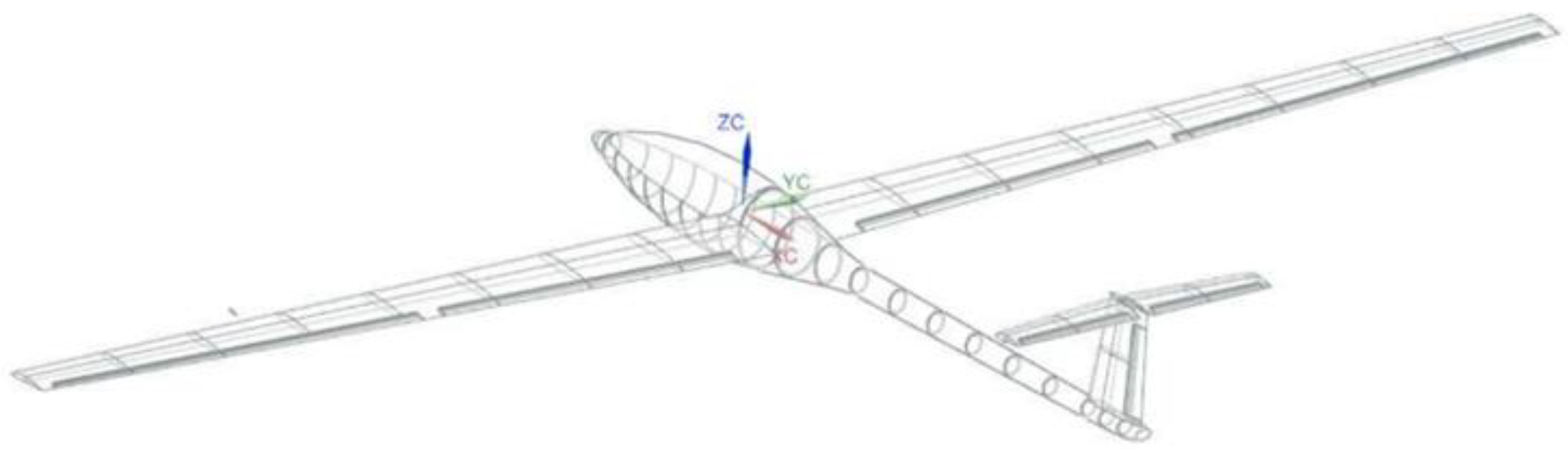
Models of individual aircraft elements have a common Cartesian coordinate system. The ZX plane in this system is the plane of symmetry in the YZ aircraft, the plane YZ is the vertical plane tangent to the ZX plane passing through the point of intersection of the leading edge with the XY
x-axis, and the plane XY is the horizontal plane passing through this point (
Figure 1).
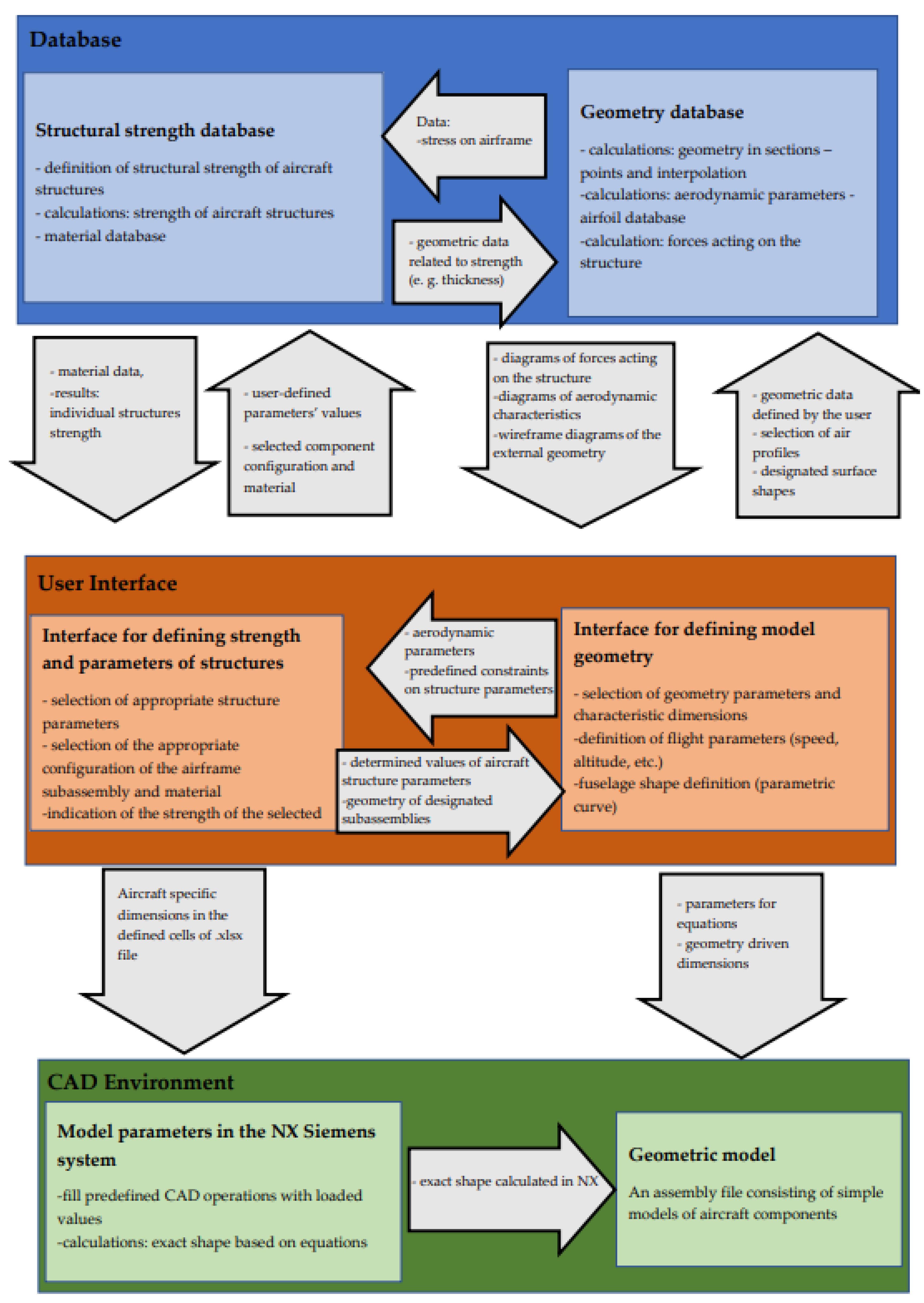
3. Software Structure
The designed software consists of a modular workbook containing spreadsheets responsible for individual fields of aircraft construction and generative models created using the Siemens NX programme (
Figure 2).
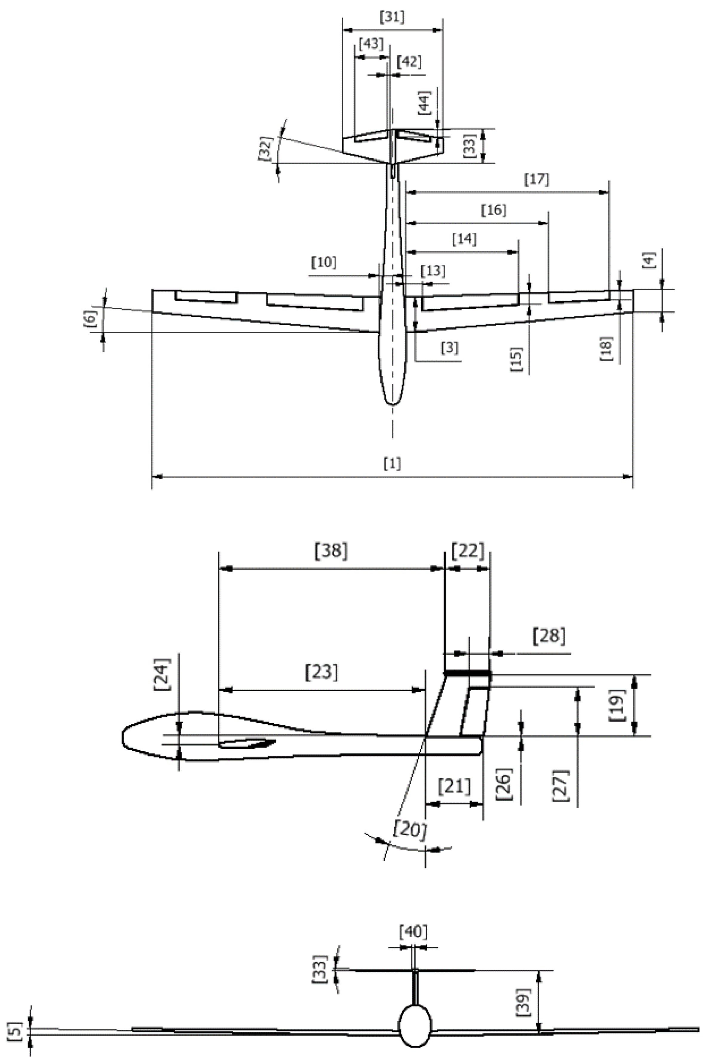
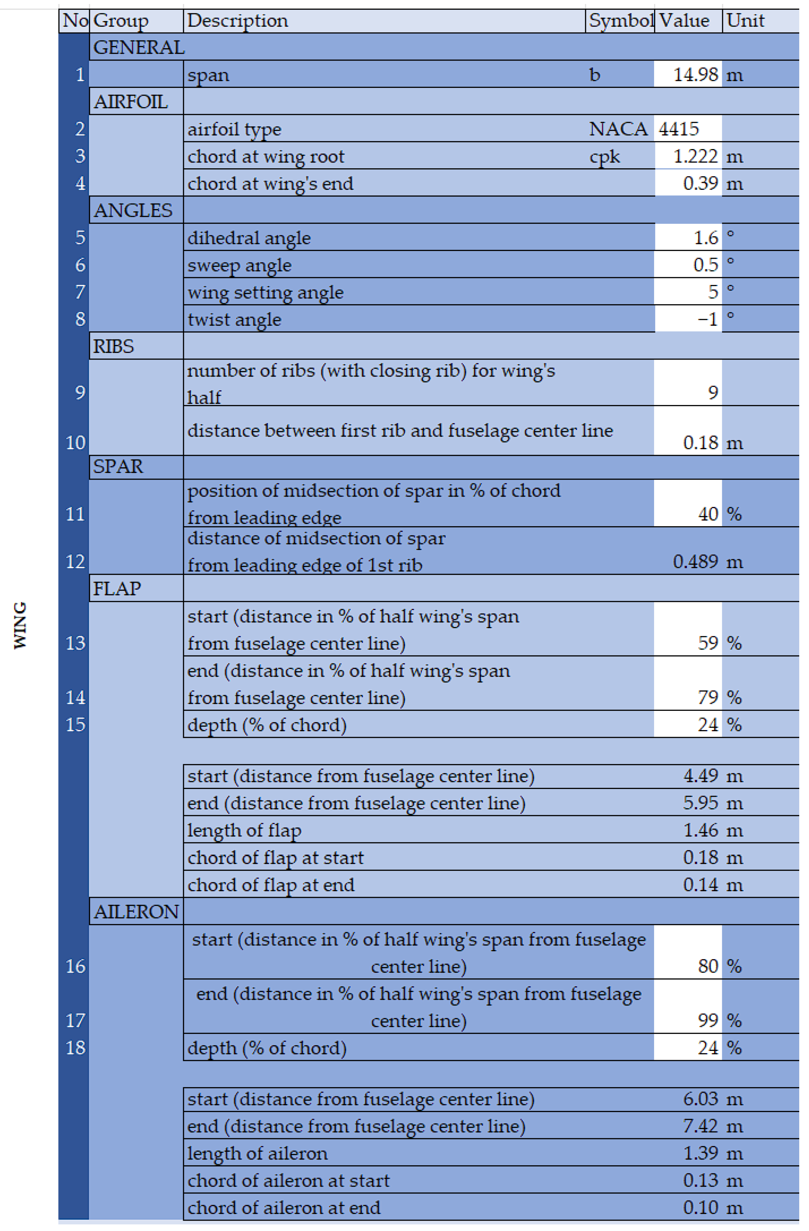
The geometry of the airframe is determined using the “Geometry interface” table. It contains a list of geometric parameters necessary for a complete description of the structure. To facilitate the identification of geometric parameters, schematic drawings with marked parameter identification numbers were created (
Figure 3). Each parameter has a unit that is used in the calculation and is reflected in the model.
Aerodynamic parameters are used only for calculations within an Excel workbook. The situation is different in the case of the geometry of the aerofoil. The representation elements of the profile shape are coordinates from a few to several dozen points in a two-dimensional form. They are stored in the .csv file. While Excel calculations are based on the interpolation of the points that define the profile, the shapes based on aerofoils in Siemens NX are defined using the equations for coordinates. For this reason, the format of the representation of points in the source file and the model are incompatible. The trade-off between simplicity in transforming the shape described by the imported points to adjust the geometry, calculating dependent geometries (such as the radius of the caisson, surface area, and spar height), and preparing equations for import using the generative model and the complexity of the formulas and the number of dependencies led to several restrictions on entering the coordinates into the worksheet.
After reading data from the xlsx file to create geometry in the model, elements are built by defining characteristic cross-sections. For all elements except the fuselage, their geometry is considered at the beginning and the end of the element. The next step is to connect the cross-sections using linear interpolation and, in the case of the fuselage, using guide curves.
In the case of a wing, a curve is created in a two-dimensional plane using the equations that define the aerofoil. This two-dimensional representation is positioned appropriately in space using the “y” coordinate of the model, the wing buttock line (WBL). After the appropriate transformation of the generator’s equations using the “law curve” tool, a curve is created, for which the values “x” and “z” are described using the transformed equations. For the root of the wing, the value of the coordinate “y” is equal to the distance of the first rib from the axis of the aircraft (WBL 0), while the tip of the coordinate “y” for the wing is equal to half the wingspan.
The skin of the wing half is formed as a surface extension using curves. This surface is thickened inwards using the thickness defined in the Excel sheets. This is one of the solids visible in the model.
Subsequent solids are the volumes of the ribs. They are created at equal distances in the number defined in the workbook. All of them are of equal thickness, and their outer outline is defined by the inner outline of the wing surface cross-section.
The next solid created is the spar. It is formed similarly to the plating—it is a swipe through two curves at the ends of the half of the wing. The width and thickness of the shelves, as well as the thickness of the web, are defined by the user in spreadsheets, while the height of the spar is calculated using Excel sheets. The lack of differentiation in the thickness of the wing surface and the spacing of the ribs is a consequence of the simplification assumptions at this stage of design.
In the case of the strength of user-defined parameters for individual structures, the whole procedure is an iterative method consisting of adjusting each of the values until the indicators regarding the safety factor indicate the correctness of the selection for each of them.
All calculations are carried out automatically in the Excel sheet tab dedicated to the given aircraft component using analytical methods (
Figure 4). This is where the formulas are located and the necessary links between them and the user interface are set. Thus, when the user enters a given parameter, it is automatically loaded, and the strength of the component is calculated on its basis, taking into account predefined conditions containing aerodynamic parameters and aircraft flight conditions.
The wing is divided into individual sections encompassing the described values, which contain constant values, predefined values, calculation quantities, and the resulting values from dependencies stored in a given sheet. The macro functions and actions available in this environment are used to perform operations. All calculations and links between them are based on the literature on structural calculations for gliders [
25].
The user’s task is to enter the indicated values using the interface, which, based on the aforementioned formulas prepared using calculations presented in the literature [
25] and saved in the sheet dedicated to the database, are subject to verification and recalculation. After that, finally, the appropriate results of these activities are returned, which are displayed in the appropriate interface cells.
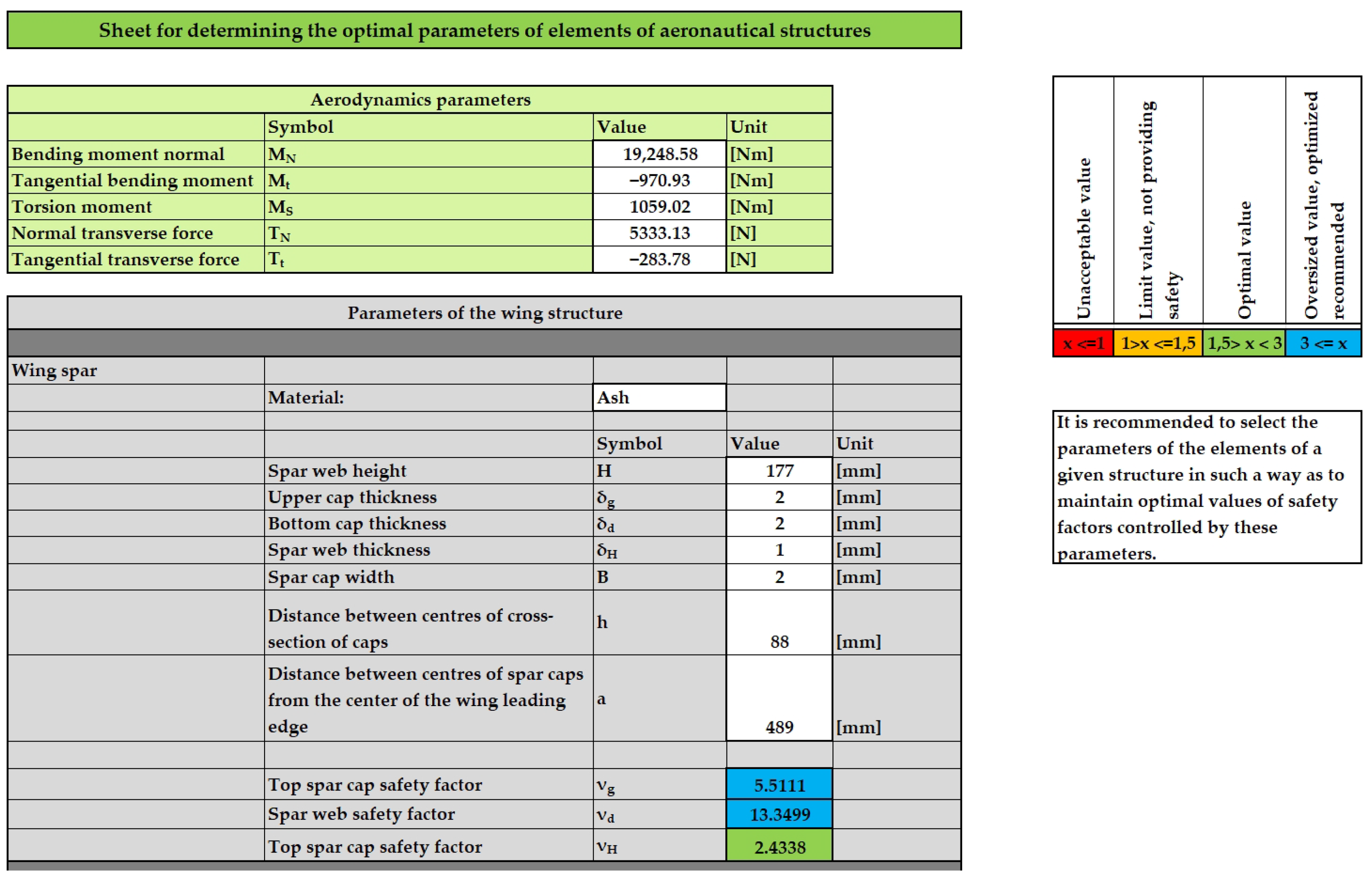
The results of the calculations boil down to presenting them in the form of a safety factor, which represents the multiplicity where the structure meets the strength stress under the used parameters. The user is informed by displaying its exact value and the colour of the label that indicates the correct or incorrect selection of one of the parameters (
Figure 5).
The value of the safety factor is influenced not only by the specific stored parameters but also by the options selected from the drop-down lists for specific configurations of aircraft assemblies and the materials used for their construction, which directly affect the method of calculation carried out and thus their results. Therefore, the user must iteratively select such quantities so that each indicated safety factor is finally within the optimal range to continue reading it in the Siemens NX environment.
When the selection of all options and parameters is complete, it is possible to save all operations and read them directly in the parameterisation window in the Siemens NX system by updating all model references to the Excel worksheet cells containing the parameter values for all aircraft components.
The software consists of spreadsheets and a CAD model stored in one folder. After entering the data and verifying it in the spreadsheet, the work is completed accordingly, the model file is opened, and the CAD model parameters are updated.
At this stage, verifying the correctness of the data boils down to entering information about typical values and warnings about exceeding them—the acceptable range of parameters is much larger than recommended; hence, there are no restrictions on the input.
An aerodynamic data module is present in the interface. These data also include general flight and aircraft parameters that significantly affect performance, such as mass, flight velocity, or the planned flight altitude.
The strength calculation module, which is also prepared, is used to adjust the geometry to the loads that occur in flight. Data are entered into this module using the “Interface” tab.
The user interface consists of parameter tables with descriptions. Some parameters are limited according to the capabilities of the software. The white fields are filled in by the user (
Figure 6).
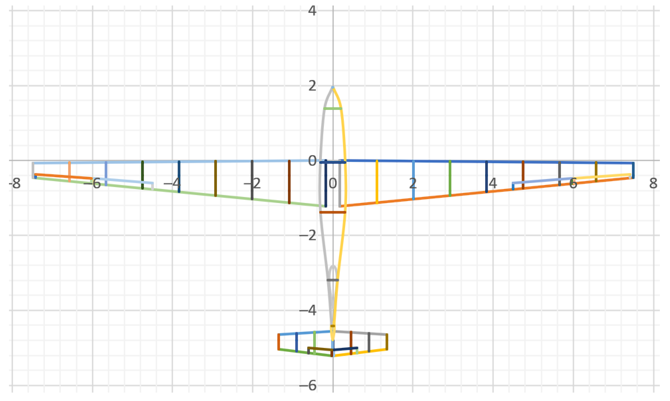
Working with the spreadsheet begins with entering the geometric parameters and basic flight mission data expected by the user. At this stage, it is possible to verify the accuracy of the data using graphs imitating the shape of the airframe in the model (
Figure 7).
The next step is to match the geometrical parameters to the aerodynamic requirements. Each element—wing, vertical and horizontal stabiliser, etc.—is divided into segments. The segments are characterised by cross-sections and then linearly interpolated. The number of segments for the wing is equal to the number of ribs, which can be up to 20 segments. For each segment, all geometrical data are calculated, e.g., chord, angle of attack, and cross-section surface area. To obtain some geometry-related parameters, differential equations are solved using substitution, with accuracy up to 0.001 mm in the case of caisson radii. Then, the points that define the outline are positioned in space. For each section, aerodynamic properties and forces are calculated using the methodology described in [
25]—the parameters are calculated analytically for each segment using the aerofoil database, requested flight parameters, and introduced geometry and then subsequently added. The spreadsheets automatically recalculate the parameters when the input changes.
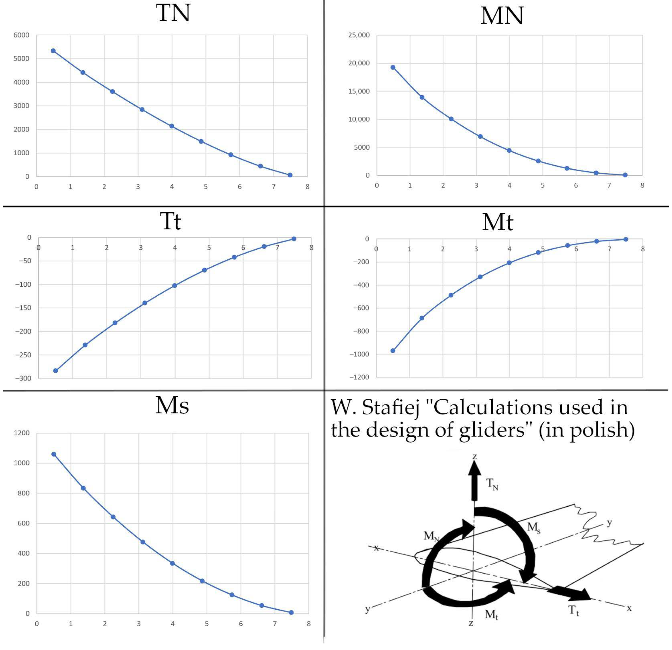
Aerodynamic parameters are checked using graphs and numerical data presented in the tables. The geometric and aerodynamic parameters are used to determine the forces that act on individual elements of the aircraft frame (
Figure 8). Based on these forces, geometric parameters related to the strength of the structure are selected.
The main purpose and method for operating the module that calculates the strength of individual airframe structures were to process the quantities selected by the user and inform about the strength of each of them and the extent to which they fulfil the basic strength conditions.
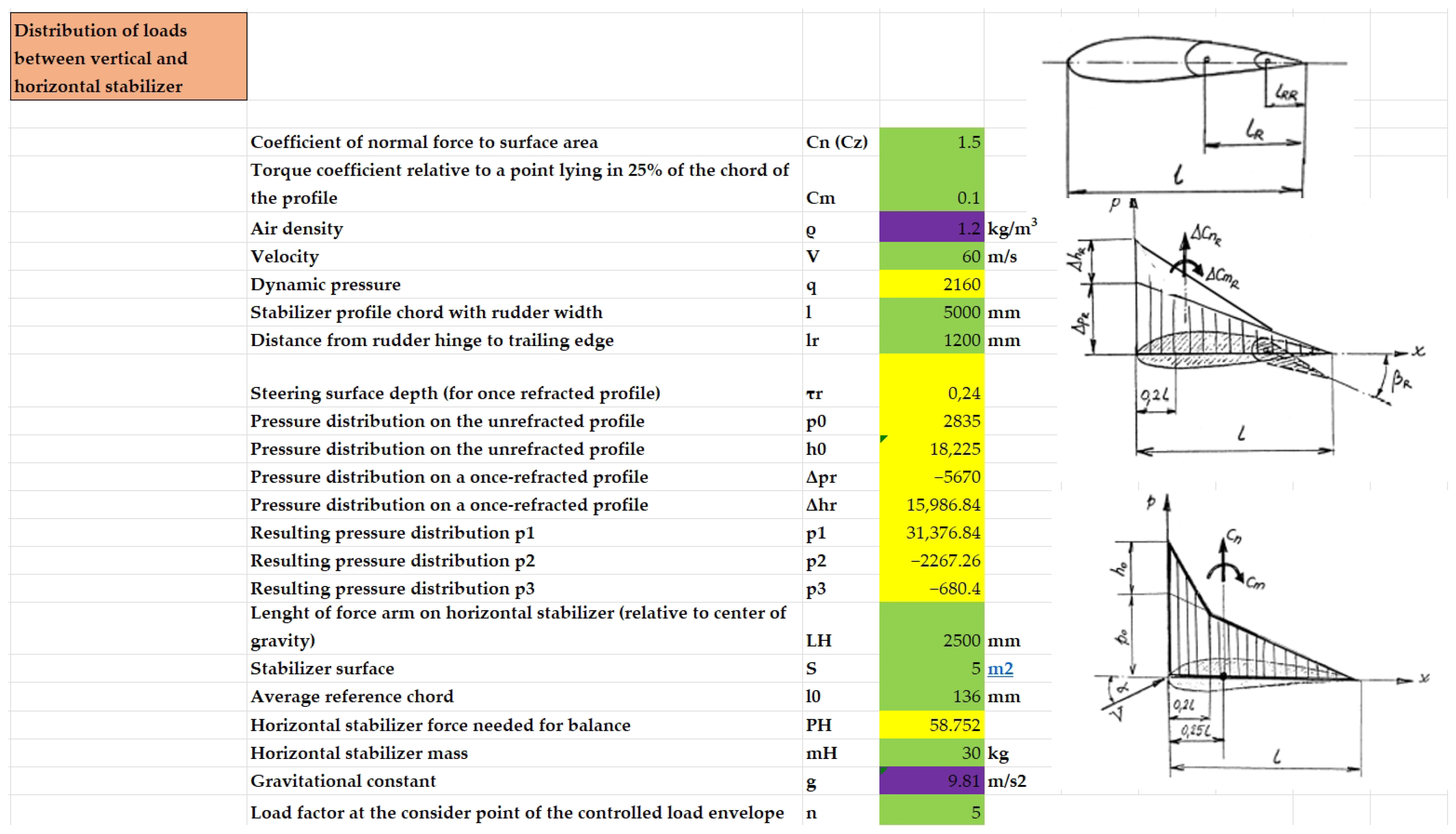
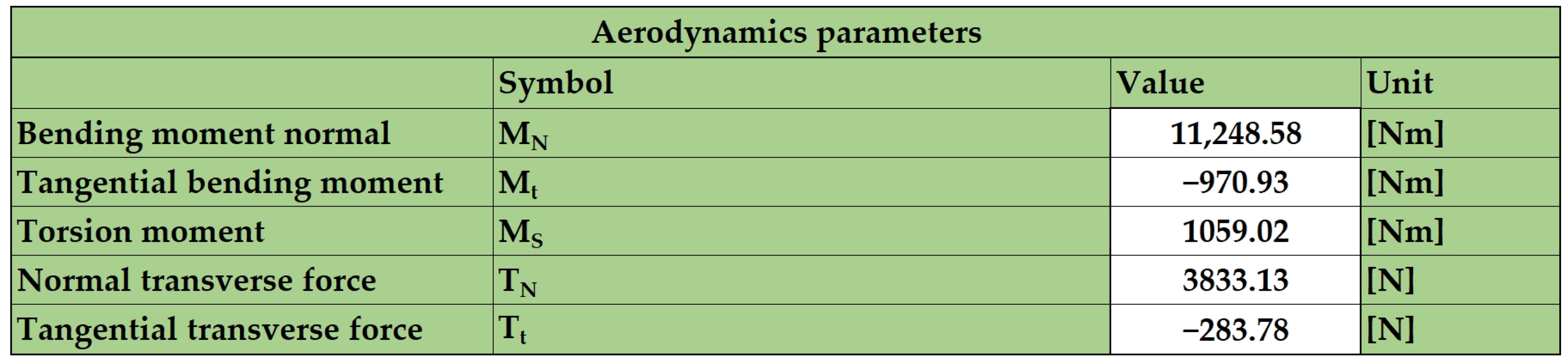
The spreadsheet consists of a part to enter or read data on the aerodynamic parameters of the aircraft structure (
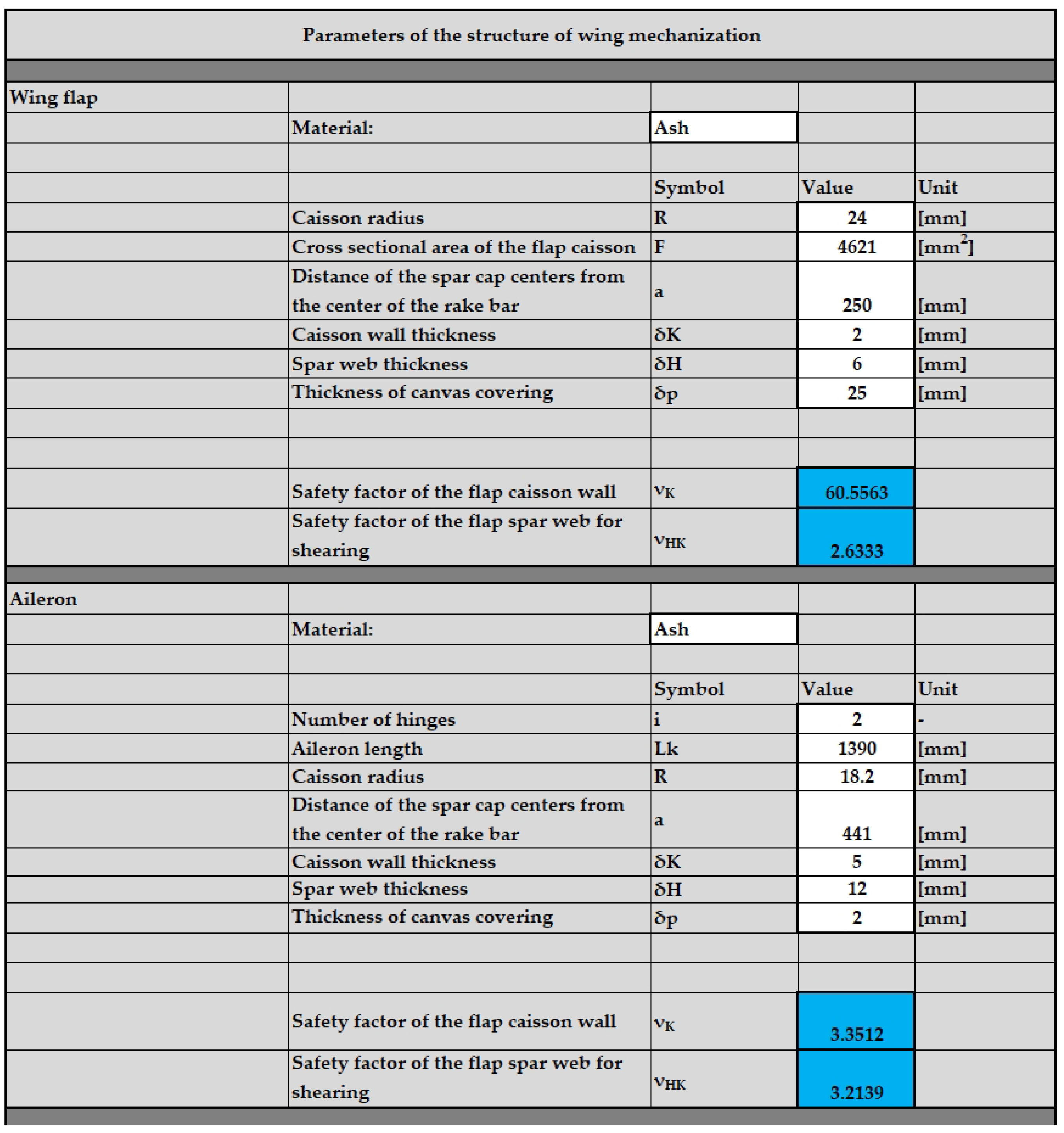
Figure 9); using this part, it is possible to define the exact values of aerodynamic forces and moments of force acting on a given aircraft structure. The spreadsheet also contains a part in which the user manually defines the physical values for each of the aircraft assemblies, where he/she is automatically informed of the correctness of the defined data (
Figure 10).
Strength verification begins with the calculation of all individual aerodynamic forces for the aircraft assembly under consideration. Then, using drop-down lists, the user selects a specific configuration for the assembly (e.g., the layout of horizontal and vertical stabilisers), as well as the individual construction materials available for the described structures.
All dependencies and calculations result directly from the aforementioned literature on calculation methods used in the process of designing aircraft structures. There is a direct reference to the methodology of aircraft design, which is based on classic methods for designing these types of structures, which was transferred to the content of the database sheets. The procedures contained therein are very similar to the procedures used for designing aircraft described by other sources in the literature, e.g., those used in the book by D. Raymer [
4]; thus, they do not require a detailed description of the used formulas due to the extensiveness and diversity of the entire content.
Once each of these quantities is determined, the user proceeds directly to the determination of the values defining the individual elements of the airframe, each of which has a direct impact on the calculated structural strength. This is expressed as a safety factor, informing the user of its range and the degree to which it provides strength for that particular aircraft structure. Strength calculations are carried out directly using a database sheet on all strength data and relationships between quantities.
The selection of each value must be completed so that each safety factor displayed in the interface window indicates, as described, a sufficiently high strength for each structure.
After verifying that the geometric, aerodynamic, and strength parameters are correct, it is mandatory to save the spreadsheet. Generative models in Siemens NX are updated to a saved set of parameters by manually forcing link updates; automatic updates of parameter functionality are not supported in the current NX release.
The model generated using the software should be exported to step format with the selected option ‘export only visible parts’ and then corrected and detailed or used as a template for a detailed design. This is a task belonging to the next stage of the design process—it is not included in the developed software presented in this paper.
3.1. Database
As part of building the knowledge base, it was necessary to specify which of the other components would be developed within the scope of this project. Thus, it was determined that all information and verification calculations regarding structures such as the fuselage, wing mechanisation elements, rudders, and elevators, along with load, would be collected and placed inside the database structure. In addition to the selection of a list for a given component, which is the main component of the airframe, it was also decided to make it possible for the user to select various configurations of the indicated structures, for which the knowledge base was additionally completed. Of these, the user can choose the type of construction, e.g., for the fuselage, the user can choose a monocoque, semi-monocoque, composite, or wooden structure, etc., using the created databases of construction materials (
Figure 11).
The goal set in the preparation of the database was to obtain, in the final effect, a set of information that enables verifying whether the performance of the calculations for a selected aviation structure meets the requirements of the given conditions. This result was achieved primarily using appropriate sources of knowledge in this field of aviation technology and the adapting their content to the needs of the developed software. As a result of all these activities, a sheet containing data and calculations was created, which semiautomatically provide the opportunity to define specific parameters of glider/aircraft components and enable the transfer of information to the extent to which they meet the specified strength conditions. The content of this document consists of tabs dedicated to assemblies such as
In addition, it contains tabs defining material constants used for strength calculations and determining the magnitudes of forces and moments resulting from aerodynamic phenomena acting on the elements of the aircraft. These activities were initiated to create a knowledge base focused on a clear record of all dependencies in the sheet, appropriate marking of features to be defined by the user, automatically calculated quantities, and quantities that should be read from other spreadsheet tabs. Then, where necessary, mutual relations between sheet cells were prepared, using, among others, macro tools and functions available in MS Excel. At the very end, the operation of the resulting system was checked.
Initially, attempts were made to implement aerofoil data in a form available directly in libraries: a file in CSV format separated by commas. This would have allowed us to enter any profile available in the external database. However, the available files turned out to be incompatible for several reasons.
On the one hand, the aerodynamic characteristics are generated exclusively for one Reynolds number (Re). On the other hand, the presented software calculates the Reynolds number and selects the appropriate characteristic based on the parameters of the airflow. Using ready-made files available in profile libraries would entail storing several files in a folder or multiple sheets in a file for one profile. Bearing in mind that a sufficiently large profile library would require several times more files/sheets, such a solution was rejected as ineffective.
Therefore, a database was created in an Excel spreadsheet, which contains aerodynamic coefficients in increments of 0.1 to 1, depending on the source fidelity. Each spreadsheet contains aerodynamic coefficients for a given aerofoil for a number of different Reynolds numbers.
3.2. Interface
Regarding the user interface, all activities primarily consist of an appropriate extension of the scope of database content to allow parameters to be determined for all the aircraft structures considered. Additionally, drop-down lists were implemented that enable quick selection of the configuration of a given airframe assembly and engineering material. In addition to the functions in the interface and the data it contains, appropriate colours were used, and the entire workspace was extracted so that it did not penetrate the spreadsheet background along with filling and adding borders to empty cells. The colour scheme for each element was based on the principles underlying human perception and association of colours; thus, the following colours were used for the given functions:
White—empty areas and free spaces requiring editing;
Red—communication about critical situations and communication about an error occurring;
Yellow—warning indicating a place requiring the user’s attention;
Green—message about the optimal choice;
Blue—indication of a large stock in terms of determined parameters;
Light green—area concerning aerodynamic parameters, forces, and moments;
Grey—used to fill the interface canvas.
The main assumption of the interface was that there would be rows in which the user enters values for geometric quantities that he/she assumed earlier. After their introduction, the quantities are analysed using the appropriate mathematical expressions. The feedback from these expressions returns safety factors for the given components of the wing structure, indicating the appropriate or inappropriate selection of one of the parameters.
Building appropriate tables in the interface tab allowed us to create further relationships between the cells used to enter the input data, the cells used to return information in the form of safety factors, and the appropriate cells contained in the tab with the calculation structure for strength parameters. Thus, communication between the tabs was shaped, which allowed for proper data exchange between them.
4. Results
The correctness of the models was verified using modelling of digital twins for production gliders, specifically, SZD-56-2 Diana 2 [
27] and SZD-32 Foka 5 [
28].
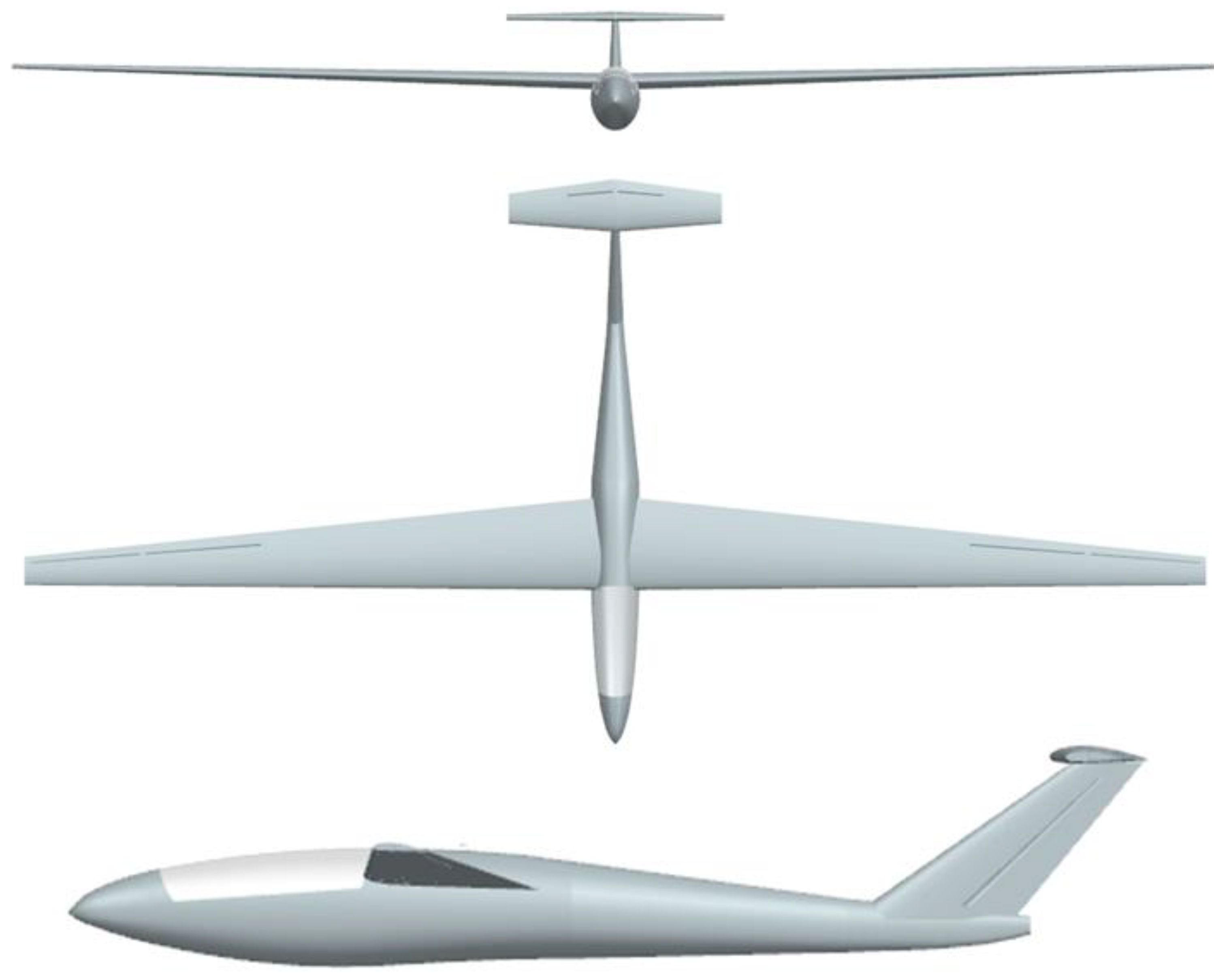
The Diana 2 glider is a medium-wing, T-tail glider, which is an extremely modern composite construction with a variable profile wing. The manufacturer provides basic dimensions, such as a span of 15 m and a fuselage length of 6.88 m.
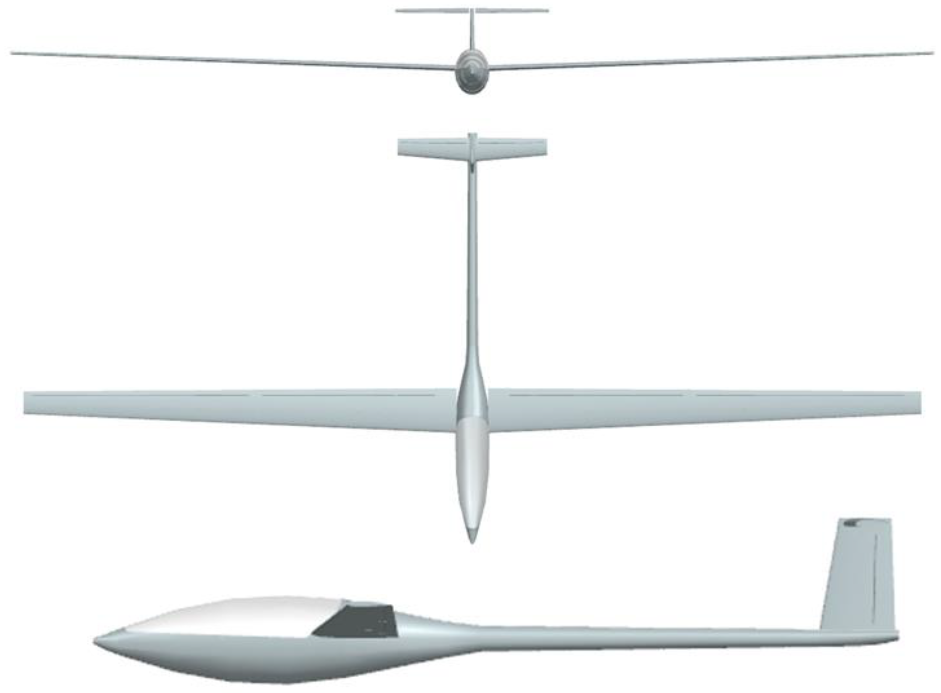
The complexity of modern designs resulted in a great simplification of the parameters in the Diana 2 model representation. For this reason, an attempt was also made to reproduce the shape of the historical glider, SZD-32 Foka 5. The first flight occurred in 1966, and work on it began in the 1950s. It is a high-wing, wooden glider with a T tail.
Based on available glider views and published parameters, all necessary dimensions were used to create as close to a geometric imitation as possible.
Using the software, glider models were created to simulate Diana 2 (
Figure 12) and Foka 5 (
Figure 13):
Due to the complexity of the construction, necessary simplifications were made when transferring the shape of the Diana 2 glider into the software. The outline of the wing was changed to trapezoidal, and the aerofoils were changed to ones available in the database, such as NACA4418 for the wing. However, the shape of the fuselage was preserved. Due to the simple design of the Foka 5 glider shape, the simplifications were only minimal.
Apart from aerodynamic-related geometries, the other geometric parameters were practically identical to the design of Diana 2. The calculation of the stall speed was performed using software based on Equation (1).
The stall speed varied greatly—it was almost 1.6 times greater than the original. This is probably due to the simplifications made to the wing. Diana 2 has an optimised wing profile that was created by Prof. Kubryński, who significantly modified it along the wingspan using advanced analyses. When comparing the stall speed of the calculated structure with Diana 1, which has similar dimensions and a less advanced design, the difference was no longer so great. In this case, it was overstated by 10 km/h, that is, 1.12 times. It is thus clearly visible that the greater simplification, the greater error.
Regarding a historical glider with a simpler design, it was possible to reproduce both the shape and aerodynamic parameters because Foka 5 was built in large part using the NACA4415 profile. After entering the new profile into the database, results consistent with the flight parameters of the structure published by the manufacturer were obtained. The difference in the calculations for the stall speed was 1.8 km/h (3%), while the minimum drag speed of the wing was identical to the published value (
Table 1).
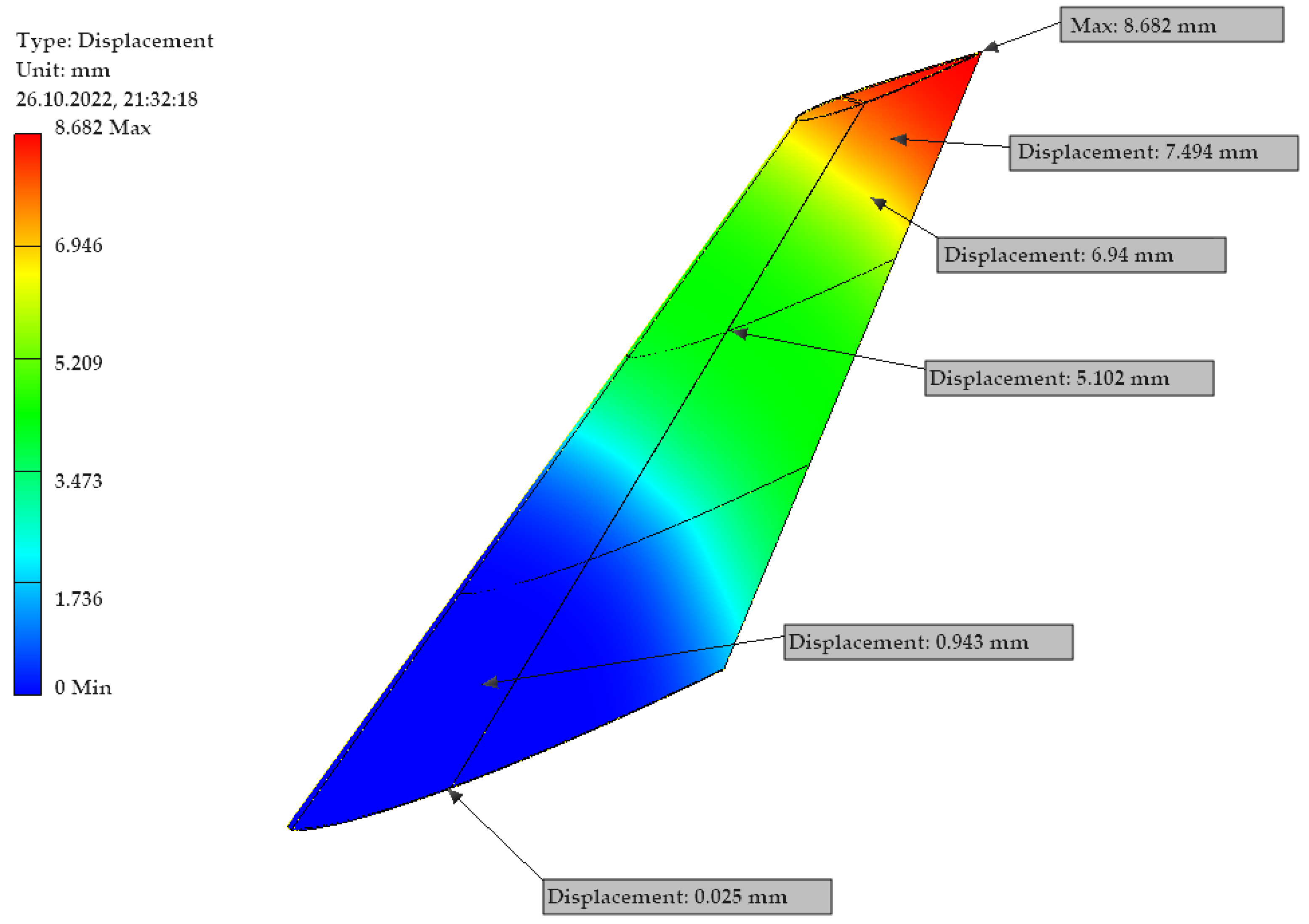
To determine whether the used equations and models correctly imitated the real-world cases, and to ensure the proper exchange of data within the software, we decided to perform a verification with real-world data. This task was accomplished using a strength analysis applied to the geometric models for a given aircraft assembly along with calculated quantities defining its exact parameters. For this purpose, the finite element method FEM was chosen, which was applied using the appropriate module available in the Autodesk Inventor environment. It should be noted that this evaluation was applied as a method to verify the accuracy of software itself. The presented evaluation examples are not mandatory to obtain results from the software, like strength-related parameters or any others. There is no need to perform FEA analysis for every iteration of the conceptual design with the presented software.
The most important step was to verify the calculated data defining the selected parameters of a given aircraft assembly using an Excel spreadsheet. Defining the following parameters using the functions contained in the sheet was associated with safety factors for a given structure, taking into account further elements such as:
The magnitude of these safety factors, depending on the predetermined range in which they were located, determined how many times the calculated stresses acting on the structure were smaller than the previously determined hazardous stress. Thanks to this, it was possible to select all sizes of the considered component, guaranteeing consistency in the entire structure and its strength during the action of forces formulated with the help of a spreadsheet.
The test was carried out on selected components separated from the aircraft, specifically, a simpler and more accurately reflected glider, the Foka V. This procedure was primarily aimed at shortening the time needed for strength analysis and resulted from the lack of any representation of structural nodes between the modelled compositions. According to the above, the following components were checked:
Horizontal stabiliser.
Wing flap;
Wing aileron;
At this stage, a decision was also made to simplify some models that contain, among others, cut-outs that enable ailerons or rudders to be placed in them. This decision was dictated primarily by the fact that at the stage of conception, these elements did not have precise values defining their strength, and the calculations carried out with the created software did not take them into account at this stage. Accordingly, their application in models subjected to strength analysis would result in such a structure not exhibiting the properties presented by the created knowledge base.
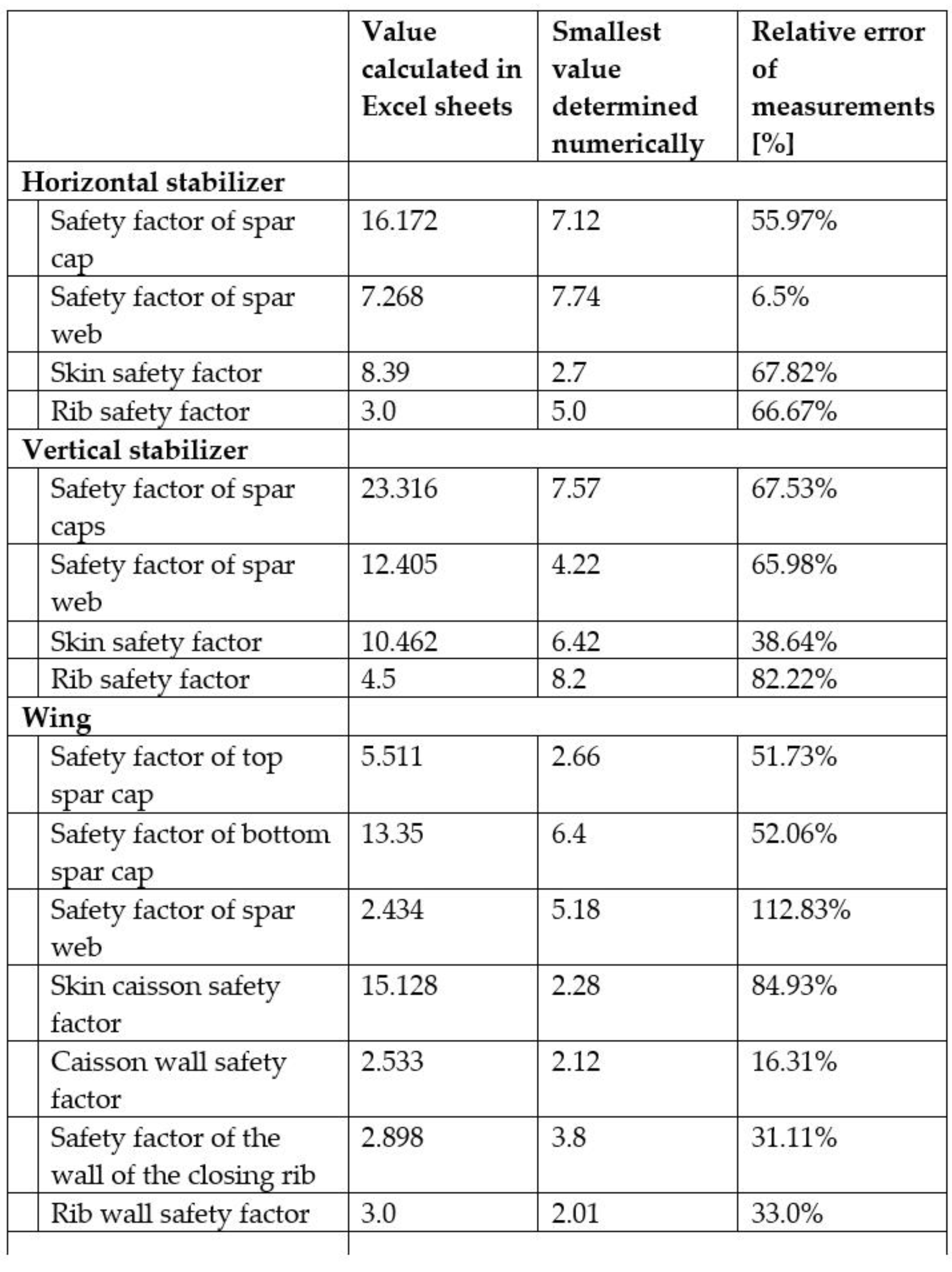
As part of this study, the relevant geometric parameters of subsequent glider components were defined, for which the safety factor should be 2.5 or more. On their basis, CAD models were generated, which were then subjected to strength analysis. The individual simulation results showed some errors resulting from incorrect interpretation of the programme regarding contacts at the boundaries of the designated central surfaces. Despite these inconsistencies, it was possible to read the necessary values on the basis of other data and determine the degree of correctness for the selected parameters. A comparison of the results is shown in
Figure 16.
Almost all elements of the glider components met the assumption of a minimum value of the safety factor. Based on a compilation of the results determined with the spreadsheets and the values obtained using the strength analysis, some deviations were noted between them. However, it should be noted that the basic values assumed for the safety factor were close to 2.5. Taking into account a certain tolerance related to the measurement error resulting from the strength analysis carried out, it can be assumed that these results meet the expectations to a sufficient extent. The remaining results met the assumptions regarding the level of the safety factor. Thus, these results confirmed the sufficient correctness of the interface and knowledge base to determine the above-mentioned parameters of aircraft structures.
5. Limitations and Solutions
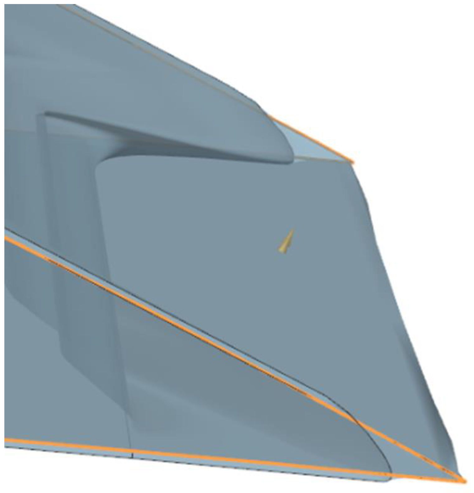
The main problem we encountered was profile scaling. Points describing the profile on any scale were allowed. These points were imported using the method based on the CSV coordinates file; however, the profile was not subjected to scaling, rotation, or translation prior to its import into Siemens NX. These transformations were applied after importing points into the model using the “Scale Curve” function and the “Pattern Feature” function several times. When normalised points were imported into the range [0; 1] and the curve based on it was scaled, curve deformations were visible.
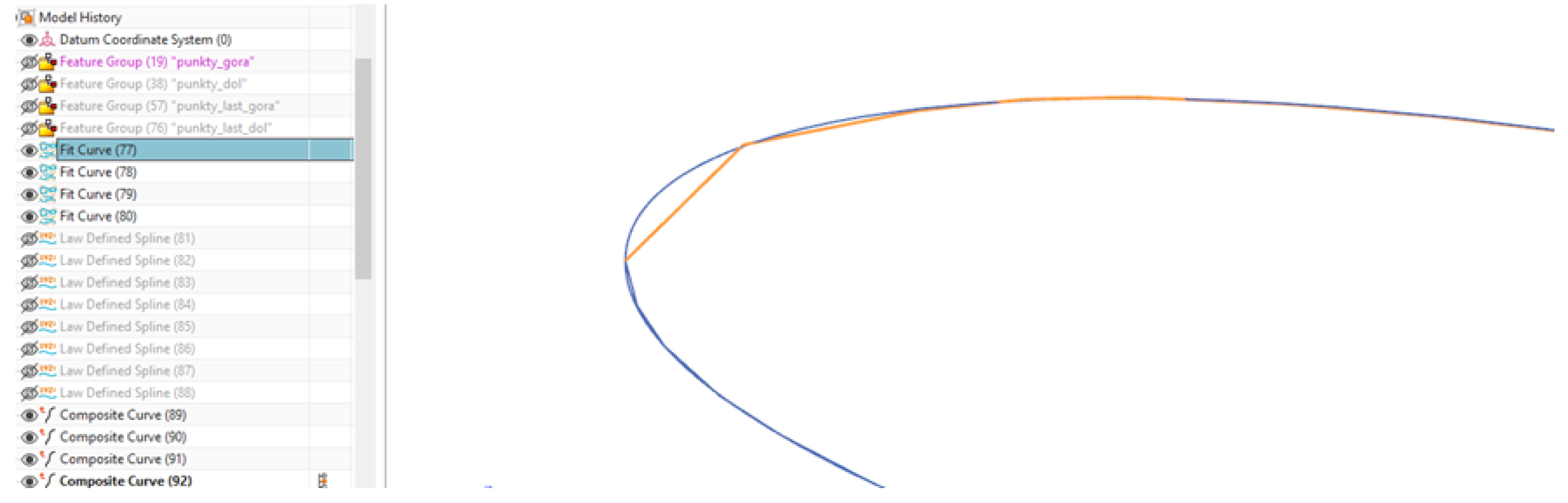
In addition, Siemens NX does not provide an approximation for a curve passing through points using a Catmull–Rom curve, but rather it uses a polynomial curve. During this study, problems related to the Runge phenomenon were revealed—at the ends of the profile, there were deformations greater than the distances between successive points (
Figure 17).
It was considered necessary to enter the profile shape in an exact, not approximated, form. For this purpose, a NACA profile generator was used, directly applying the equations describing the shape of the profile. A comparison of shape reproduction accuracy is shown in
Figure 18. Approximated shape is highlighted in orange, exact shape in blue.
In this way, errors in the transformation of the external surface, such as those shown in
Figure 17, were eliminated.
It is possible to expand the capabilities of the current software, as the presented models are an implementation of the most basic functions. The modularity of both the spreadsheets and models allows for trouble-free attachment of subsequent modules in future work.
The first important limitation of the current version of the software is its ability to build geometry based solely on four-digit NACA profiles. The equations for NACA five-digit profiles are known, which means that such a generator could be adapted to the model without much difficulty. The generator contains two sets of equations: one for generating the curve shape and the second for scaling, rotation, and translation. To enter the generator of five-digit NACA aerofoils, it would be required to add a conditional statement to the transforming equations to change the selection of curve equations from the four-digit NACA profile generator into the introduced NACA five-digit profile generator.
6. Summary
The presented work focused on the construction of software to support the design and generation of aircraft/glider geometry and to assist with verifying the calculations of structural features of aircraft structures applicable to generative models for aircraft design. A draft version of this article was published as a preprint. As part of this, a detailed review of studies in the literature was carried out on generative models and knowledge-based systems. As the next stage of this work, here we presented the process for creating an appropriate database containing, among others, data on construction materials and calculations for individual quantities necessary to determine geometric parameters for generative models. We then completed the integration of design verification methods used in aircraft design with methods for determining structural features in the generative models and implementation of the entire composition into the Siemens NX system. The sample parameters were defined, and models were generated, which were subjected to strength analysis in order to verify the correct operation of the entire software.
The designed software addresses the needs resulting from current trends in the field of aviation engineering and is a great foundation for creating a full-fledged programme that allows for accelerating the design of aircraft structures. Further work on the software will certainly increase the range of possible types of aircraft, as well as the configurations available for them. This would make the software more universal and appealing to a wider audience and expand the possibilities of its use.
7. Conclusions
The development of the system required very tedious and time-consuming work, consisting of testing many different options for model generation automation solutions and choosing the most effective solutions with compromise. During this process, very well-developed textbooks were used, constituting a compendium of design knowledge, which greatly improved the process of identifying knowledge. Usually, however, the designers of such systems are not in such a comfortable situation, and the process of knowledge acquisition becomes a bottleneck in the process of building systems using generative models. The developed model can serve as a foundation for further design and should only be considered as a preliminary form of the entire aircraft. Many details of the structure, including the load-bearing structure, mechanisation of the wing, and integrated subsystems, will be designed using this model in the next steps of our project. The developed system is an excellent foundation for the initial design of an aircraft, and its application allows for the quick generation of a verified aircraft concept. This project is innovative due to the combination of knowledge and methods of aircraft design and merging them with 3D design software. At the same time, it allows for the creation of pre-optimised models of aircraft structures which, supported by the created knowledge base, enable computational initial verification of the designed structure without requiring extensive knowledge of aviation or general engineering from the user to obtain reliable results. Such programmes and systems are not widely available, especially for home use. Due to the extensive knowledge base and issues necessary to create such a programme, and its possible further application for practical purposes, this issue is considered by research units and specialised units dealing with designing aviation structures, etc. Due to the limitations related to the availability of programmes supporting and enabling work on the presented software, the software currently allows for the creation and verification of aircraft structures from the selected range of aircraft classes, which are gliders. Therefore, it is a step toward addressing the limited possibilities and availability of resources allowing, inter alia, an ordinary user to use such software.


