Article

Fundamental Study of Premixed Methane Air Combustion in Extreme Turbulent Conditions Using PIV and C-X CH PLIF

by
Md. Amzad Hossain
1,*,
Md Nawshad Arslan Islam
1,
Martin De La Torre
2,
Arturo Acosta Zamora
3 and
Ahsan Choudhuri
1
1
Aerospace Center, Department of Aerospace and Mechanical Engineering, The University of Texas at El Paso, El Paso, TX 79968, USA
2
Engineer, Blue Origin, Cape Canaveral, FL 32920, USA
3
Engineer, Intel Inc., Portland, OR 97124, USA
*
Author to whom correspondence should be addressed.
Aerospace 2023, 10(7), 620; https://doi.org/10.3390/aerospace10070620
Submission received: 27 May 2023 / Revised: 29 June 2023 / Accepted: 6 July 2023 / Published: 8 July 2023
(This article belongs to the Special Issue Heat Transfer, Combustion and Flow Dynamics in Propulsion Systems)

Abstract

:
This paper presents the flow and flame characteristics of a highly turbulent reactive flow over a backward-facing step inside a windowed combustor. Flow and combustion experiments were performed at Re = 15,000 and Re = 30,000 using high-resolution 10 kHz PIV and 10 kHz PLIF diagnostic techniques. Grid turbulators (Grid) with two different hole diameters (HD of 1.5 mm and 3 mm) and blockage ratios (BR of 46%, 48%, 62%, and 63%) were considered for the turbulence study. Grids introduced different turbulent length scales (LT) in the flow, causing the small eddies and turbulence intensity to increase downstream. The backward-facing step increased the turbulence level in the recirculation zone. This helped to anchor the flame in that zone. The small HD grids (Grids 1 and 3) produced continuous fluid structures (small-scale), whereas the larger HD grids (Grids 2 and 4) produced large-scale fluid structures. Consequently, the velocity fluctuation was lower (~25.6 m/s) under small HD grids and higher (~27.7 m/s) under large HD grids. The flame study was performed at Φ = 0.8, 1.0, and 1.2 using C-X CH PLIF. An Adaptive MATLAB-based flame imaging scheme has been developed for turbulent reacting flows. Grids 1 and 3 induced more wrinkles in the flame due to higher thermal instabilities, pressure fluctuation, and diffusion under those grids. The flamelet breakdown and burnout events were higher under Grids 2 and 4 due to higher thermal diffusivity and a slower diffusion rate. It was observed that the flame wrinkling and flame stretching are higher at Re = 30,000 compared to Re = 15,000. The Borghi–Peters diagram showed that the flames were within the thin reaction zone except for Grid 1 at Re = 15,000, where flames fell in the corrugated zone. It was observed from PIV and PLIF analyses that Re and LT mostly controlled the flame and flow characteristics.

1. Introduction

The design and development of next-generation high-speed engine combustors such as scramjets, ramjets, and diesel engines require an in-depth understanding of high-intensity turbulent combustion [1,2]. The study of turbulent premixed combustion is always difficult, especially when it comes to stabilizing the combustion and detecting the flames, or finding whether is it the instability or the turbulence that controls the flame. Instabilities such as the Darrieus–Landau instability, flame wrinkling, flame straining pattern (tangential and normal), stretching rate and duration, turbulence and vorticity levels, and heat release-induced pressure gradients play an important role in turbulent flame behavior [3,4,5,6].
To better understand turbulent flame behavior, researchers developed highly accurate non-intrusive flame measurement techniques with high repetition rates in the last two decades. Among those techniques, particle image velocimetry (PIV) and planar laser-induced fluorescence (PLIF) have been widely used [3,4,5,6]. In the following discussion, the authors aim to present the advancements made with PIV and PLIF techniques, the limitations of this research work, and the rationale behind their selection of C-X CH PLIF for the flame study.
G. Troiani [7] used the PIV system to study the wrinkling of flame fronts caused by the Darrieus–Landau (DL) instability and its interaction with turbulence across various Reynolds numbers (Re) in a Bunsen setup. The instability was induced by adjusting the mixture ratio (MR) in laminar conditions and by varying the Bunsen nozzle diameter (DN) in turbulent conditions. They compared stable and unstable Bunsen flames by analyzing the vorticity generation, total flame strain, and the straining pattern of a single DL cusp. The results indicated that unstable flames with wrinkling displayed statistical characteristics typically seen in stable flames under high turbulence levels, suggesting a unified regime with some remaining distinctions. This study demonstrates that there is a correlation between flame-front instability with flame wrinkling, flame straining, vorticity level, etc. Lapenna et al. [8] have examined the impact of DL instability on turbulent propane–air premixed flames. The theoretical analysis identifies two regimes: one dominated by instability and the other by turbulence. In the turbulence-dominated regime (also known as the unified regime), the presence of turbulence hinders the formation of large-scale cusp-like structures in the flame front caused by the DL instability, resulting in reduced effects on turbulent flame propagation and front curvature statistics. As a result, the characteristics of stable and unstable flame configurations become indistinguishable across laminar to turbulent conditions. Similarly, Chaudhuri et al. [9] utilized a high-speed PIV system to examine how flames interact with turbulence in expanding premixed flames using a CH4–air mixture. The study presents information on mean flow velocity, fluctuating flow velocity, stretch rate contributions, and the movement of flame edge points. Their findings indicate non-Gaussian tails in normal straining and near-Gaussian behavior in tangential straining. Lipatnikov et al. [10] demonstrated that the pressure gradients from the heat release in surrounding flamelets can generate unburned mixture fingers that penetrate deeply into the combustion products, eventually increasing the flame surface area, flame velocity, and mean flame brush thickness. This mechanism is distinct from the DL instability and made the flame fronts move towards the leading edge of the flame brush. Chaudhuri [11] utilized the DNS to examine the finite lifetime of flame particles residing on iso-temperature surfaces of statistically planar H2–air flames interacting with near-isotropic turbulence. The particles encounter increasing tangential straining rate (Kt) and negative curvature (κ) and the flame surface mostly shifted because of the tangential strain rate. Zhou et al. [12] investigated the flow fields of premixed and stratified CH4–air flames under turbulent conditions using laser Doppler anemometry (LDA) and PIV. Their study revealed significant changes in flow behavior with varying levels of swirl and stratification, incorporating axial, radial, and tangential velocities to derive key turbulence parameters. Fan et al. [13] investigated the impact of water droplets on strained methane–air laminar flames using PIV and measured the flame speed and motion of the liquid phase simultaneously. They found that the addition of water droplets significantly reduces the flame speed and is more effective in flame suppression. These studies clearly show that turbulent flow characterization and flame detection mechanisms are very complex and demand more fundamental studies.
PLIF system has been extensively used for turbulent reacting flow combustion studies. PLIF involves the use of laser-induced fluorescence to visualize and quantify various properties, such as temperature, species concentration, and flow velocity. The PLIF system typically consists of a laser source, optics for shaping the laser beam, a fluorescent dye for tagging the fluid, and a high-resolution imaging system. When the laser beam interacts with the tagged fluid, the fluorescent molecules emit light, which is captured by the imaging system and converted into meaningful data [14]. PLIF targets the species present in the flame, such as hydroxyl (OH), CH2O, and methylidyne (CH). Among these radicals, OH PLIF is widely used in the lab [15]. The concentration gradient of OH radicals in flames is high [16]. Additionally, OH radicals are present near the flame fronts and combustion products [17]. OH also sustains for a long time in the flame. Because of these characteristics, OH radicals are suitable for tracing down the flame fronts in a highly turbulent environment. For the same reasons, OH radicals have also been used in high-repetition-rate PLIF diagnostics [18,19]. While these advantages seem prevailing, there are a few questions about the use of OH as a flame front tracer [20]. For instance, OH is slowly removed away from the flame by three-body collision reactions [21,22,23] making it difficult to trace the primary fuel reaction zone. Additionally, OH is a tracer of the radical-recombination zone, not necessarily a marker of flame front tracing [24].
The alternative way of tracing flames is to use methylidyne (CH) PLIF. Generally, CH is a suitable marker for flame front tracing. CH radicals are formed during the initial fuel decomposition. Additionally, CH is removed away by rapid two-body collision reactions. Thus, the CH radicals are present during the main course of combustion. There are three bands of CH radicals as reported by Carter’s group [25,26]: A-X (A2Σ+-X2Π (0,0)), B-X (BƩ—XΠ), and C-X (C2Σ+-X2Π (0,0)). Carter’s group stated that the C-X CH band is better than the other two bands. The reason for this is that the C-X band is effective in detecting the flame during the main phase of combustion. It provides a clear visualization of the flame’s central region, outer boundaries, and the way it extends in turbulent reacting flows. The C-X CH radical could be easily excited using the frequency-doubler dye laser commonly used for OH detection [22,27,28]. Therefore, a laser power system comprised of a dye laser and a pump laser (main power laser) can be used for C-X CH excitation. The excitation and emission spectrum of C-X CH is normally held at 314 nm [9].
Acosta-Zamora [28] studied the highly turbulent reacting flow over a backward-facing step. This study examined the flow and flame interaction at low to moderate Re conditions using both PIV and OH PLIF. Although the researcher was able to excite and detect the OH signal, the study experienced several issues in flame imaging. For example, the flame profiles were diffuse, and the flame core was not thin. This is because there was a presence of some foreign quantity, which was named the “ghost mixture quantity”. This ghost quantity gets infused into the flame core and makes the core diffuse rather than a thin, flamelet-like structure. It was very difficult to differentiate the flame reaction zone from the overall flame profile. In addition, at higher turbulence conditions, OH PLIF does not give sharp flame-front structures. It was also hard to investigate how the turbulent eddies infused into the flame core. To better detect the flame profile at turbulent premixed combustion, the study recommended using CH PLIF. Acosta et al. [28] conducted a preliminary study but were not able to implement CH PLIF because of the system’s limitation and lack of time to do the iterations. Similar recommendations have been reported in [22,27,29]. The authors in this study made changes to the laser diagnostics system described by Acosta-Zamora at The University of Texas at El Paso (UTEP) Aerospace Center. They then implemented CH PLIF for the turbulent premixed combustion study.
Based on the literature review [22,25,27,29], it is observed that CH PLIF has the potential to accurately detect flame profiles in turbulent conditions. Furthermore, most researchers, including Carter’s group, use PLIF for open flame systems. Based on a statistical analysis of 100 random papers [30], it is seen that 95% of the papers talk about open flame systems (Bunsen burners, flat plate burners, flat swirl burners, etc.) [18,25,26], and only 5% of papers talk about closed flame systems [3,28]. This clearly shows the importance of researching closed flame systems. Hossain [30] also stated that out of these 100 papers, 68% considered OH PLIF, 22% considered CH PLIF and 10% addressed other types of PLIF systems. Out of the 22 papers on CH PLIF, 5 papers used C-X CH PLIF, 11 papers used A-X CH PLIF, and 6 papers used B-X CH PLIF. This indicates that more research should be carried out using C-X CH PLIF. In addition, experimental resources on flame–flow interaction at higher-order turbulence (higher Re) remain sparse [4,29], and [31]. More study needs to be carried out under low to moderate Re or Mach conditions.
Motivated by the above-mentioned issues and limitations, the present effort aimed to demonstrate experimental methodology and post-processing techniques for imaging CH in a high-intensity turbulent flow field within a windowed combustor. A high repetition rate PLIF (10 kHz) and PIV (10 kHZ) were used to study the flame and flow characteristics. Grid turbulators (Grids) or perforated plates were used to investigate the effect of turbulent length scale (LT) on flame growth. Different Reynold numbers (Re = 15,000 and 30,000) and equivalence ratios (Φ = 0.8, 1.0, and 1.2) were considered to study the effect of mixture inlet velocities and fuel loading on flame propagation. Two Matlab-based programs were developed for flame post-processing: one for flame profile detection and another for flame edge detection. The ultimate goal of this research is to see the compatibility of the present laser system for high-speed combustion.

2. Experimental Setup and Methodology

2.1. Experimental Setup

A 304 stainless steel (SS) combustor was used to study high-speed combustion. The combustor has optical access through quartz windows located on the top and both lateral sides. These windows were designed with a factor of safety (FOS) of 3.5. The maximum chamber operating pressure is 6 bar (90 psi), and the maximum temperature is 500 °K (440 °F). The maximum thermal firing input of this combustor is 250 kW. Methane and air are premixed in a mixing chamber before entering the combustor. Air enters the mixing chamber axially, while methane enters radially in a cross-mixing arrangement. The circular flow path inside the mixing chamber is converted to a square at the mixing chamber outlet via a converter flange attached to the combustor inlet. Once inside the combustor, the mixture moves over the backward-facing step. This step offers a sudden expansion in the flow path area. Consequently, a high number of small eddies form in the recirculation zones. The eddies help to mix the burned gases with the fresh mixtures, stabilizing the flame in this area. The methane–air mixture ignition point is located at the recirculation zone. A pilot flame subsystem operating with a hydrogen–air flame is used to ignite the flammable mixture inside the combustor. After ignition, the exhaust combustion products are routed through the exhaust cooling tower and finally to the laboratory exhaust. Figure 1 shows an exploded view of the small-scale windowed combustor with the backward-facing step.
At the combustor inlet, perforated SS plates called grids (or grid turbulators) induce isotropic homogeneous turbulence inside the combustor. Grids also produce different turbulent length scale levels in the flow. Figure 2 shows the grid and the pilot flame subsystem.

2.2. PLIF Methodology

The planar laser-induced fluorescence (PLIF) system consists of three main components: a Q-switched DPSS laser (neodymium-doped yttrium aluminum garnet (Nd-YAG) Edgewave IS series), a frequency-doubled dye laser (Radiant Dyes NarrowScan HighRep Dye Laser), and an intensified high frame rate CCD camera (Speed sense 9070 with Hamamatsu C10880-01C). The pump laser produces a 532 nm beam through the tunable dye laser. The Nd-YAG pump laser has a pulse energy of 5.6 mJ/pulse (28 W) at 5 kHz and 2 mJ/pulse (20 W) at 10 kHz. The dye laser uses different dyes, oscillators, and a BBO crystal assembly to tune the laser to the desired wavelength. DCM in ethanol with a concentration of 0.55 g/L is used for CH radical excitation. The dye laser produces energy of approximately 0.25 mJ/pulse at 5 kHz. The fluorescence is detected using an intensifier equipped with a Cerco 100 mm f/2.8 lens coupled with a 3 kHz high-speed camera. The camera has a resolution of 640 × 480 pixels at 10 kHz, providing a resolution of 105.48 um/pixel. A UG-5 colored glass filter was placed on the camera lens to block visible light but allow UV fluorescence to pass through. The intensifier gate was set to 15 ns. A wavelength scan identified the 314.415 nm wavelength to be optimum for tracing flame front with C-X CH PLIF. At this wavelength, the excitation and emission coefficients of CH radicals are high. Figure 3 shows the complete schematic of the PLIF. For a complete overview of the high-speed combustion test facility and the laser diagnostic systems, readers are referred to the authors’ previous articles [28,32,33,34,35].
Several challenges were encountered during the experimentation and post-processing stages of this study. The greatest challenge was to focus the laser sheet onto the interrogation area with optimum accuracy. It was also hard to get the right excitation wavelength for the CH C-X band. In this present work, the authors have excited CH using wavelengths from 314 nm to 320 nm. The CH signals are collected at 314.415 nm as it gives better flame profiles. The authors are aware that there is a chance of having resonance in the CH PLIF system; similar issues are reported in [18,26]. In addition to the above-mentioned challenges, it was particularly difficult to detect and extract the CH signal as it tends to overlap with OH. The OH signal was reduced by optimizing cameras and intensifier parameters. The optimization of both camera and intensifier parameters depends on the flow turbulence. Dantec Dynamics studio was used to acquire the data.
The acquired data were post-processed using in-house MATLAB image processing codes. The raw images contained unwanted laser reflections, background noise, and soot. In addition, the post-processing of the raw images can also contribute to scaling errors. A MATLAB image processing code was developed to address these challenges. First, the MATLAB code was adjusted to the flame image pixel matrix to mitigate unwanted laser reflections and background noises. This adjustment protects the target area from external influence. Next, a separate MATLAB code was implemented to improve the visibility of the flame profile. The base images (without flame) were subtracted from the raw images (with flame) to improve visibility. After that, the images were converted to grayscale and webinar scale. Colormap was then implemented on both grayscale and webinar-scale images. The flame profile generated by the grayscale colormap shows higher resolution and almost no background noises. For this reason, the grayscale-induced HSV colormap is reported in this paper. Additionally, the flame profiles were magnified to observe the flame edge events. A magnification factor of two to four was used in this research. Although it makes the flame core slightly dense, this does not obstruct or influence the flame structures.
The flame edges provide a better representation of flame evolution. For this, a separate MATLAB code was established. This code flipped the HSV colormap contours. Then, the flipped images were converted to grayscale images. After that, binarization and edge detection commands were implemented in the images. For simplicity, flame edges detected by the Canny command are presented in this research. Finally, the MATLAB complement command gives a final flame edge profile. The flow chart of MATLAB image processing codes is shown in Figure 4.

2.3. PIV Methodology

A 15–1000 dual-power neodymium-doped yttrium lithium fluoride (Nd-YLF) laser with a pulse energy of 15 mJ was used for flow characterization. A series of optical mirrors guided the laser from the laser head to the combustor interrogation area. A compressed air-driven fine alumina particle (1 micron) was used as a seeding particle for flow visualization. The seeding particles were introduced at the mixing chamber to mix with the air–fuel mixture and then introduced to the combustor. Nd-YLF is a double-pulse laser. The camera records two instances when the particles travel a fixed distance. The software cross-correlates to the interrogation area and generates the velocity fields. Statistical analysis and adaptive PIV tools generate other flow characteristics such as turbulent intensity and vorticity. A complete overview of the PIV laser system, synchronization parameters, and PIV post-processing can be found elsewhere [33,34,35].
The main challenge in the PIV system was to redirect the laser beam to the laser optics sheet by 45°. The target was to create a laser plane area of 1 mm × 52 mm × 25 mm. Another challenge was to send the tracer particles to the combustor without flow interruption. The pressure on the seeding flow has to be higher than the bulk flow pressure for seeding particle introduction. The camera must also be calibrated accurately to obtain the flow field events.
Dynamic Studio was used to process the acquired images from PIV experiments. Dynamic Studio implements the image balance map to all raw images to address non-uniformities in the images. This generated light-balanced images with high contrast for easy distinguishment of the location of the particles. Dynamic Studio also utilizes a masking tool to minimize background noise in the processed images. A wall windowing function was used to resolve the wall bias. This function provides a symmetrical uniform distribution of the seeding particle within the interrogation area. An adaptive PIV function was used to adapt the interrogation area to the local seeding densities and flow gradients. The adaptive PIV was also used for frequency filtering and universal outliners detection.

2.4. Operating Conditions

The operating conditions were calculated based on the Reynolds numbers (Re), equivalence ratios (Φ), and mixture flow rates. The following two equations are used to calculate the Reynolds number and mixture viscosity:
R e = V m i x t u r e × L ν m i x t u r e
l o g ν m i x t u r e = x a i r l o g ν a i r + x C H 4 l o g ν C H 4
where Vmixture is bulk mixture velocity, x is the mole fractions, νmixture is the bulk mixture viscosity, and L is a characteristics dimension of the combustor inlet. The operating conditions are presented in Table 1 and Table 2. The pump laser, camera, and intensifier unit are synchronized so that the right flow and flame sequence was captured. The synchronization parameters are presented in Table 3.
PIV analysis generates the velocity vector contours, turbulent intensity, and vorticity contours. It also allows observing the flow characteristics at the interrogation line. The equations used to measure the flow characteristics at the interrogation line are presented in Table 4. For detailed PIV analysis, refer to articles previously published by the authors of this paper, [28,32,33,34,35].

3. Results and Discussion

This section reports the fundamental study of high-speed combustion under different grids (see Table 5 below) at various mixture inlet velocities (10 m/s (Re = 15,000) and 20 m/s (Re = 30,000)) and equivalence ratio of Φ = 0.8, 1.0, and 1.2. The PIV results at Re = 15,000 and Re = 30,000 are used to understand the flow dynamics better. The effect of turbulent length scale (LT) on flame–flow interaction and flame regime boundaries and scale factors on reaction zone are reported in this section.

3.1. Flow Field Characteristics Analysis

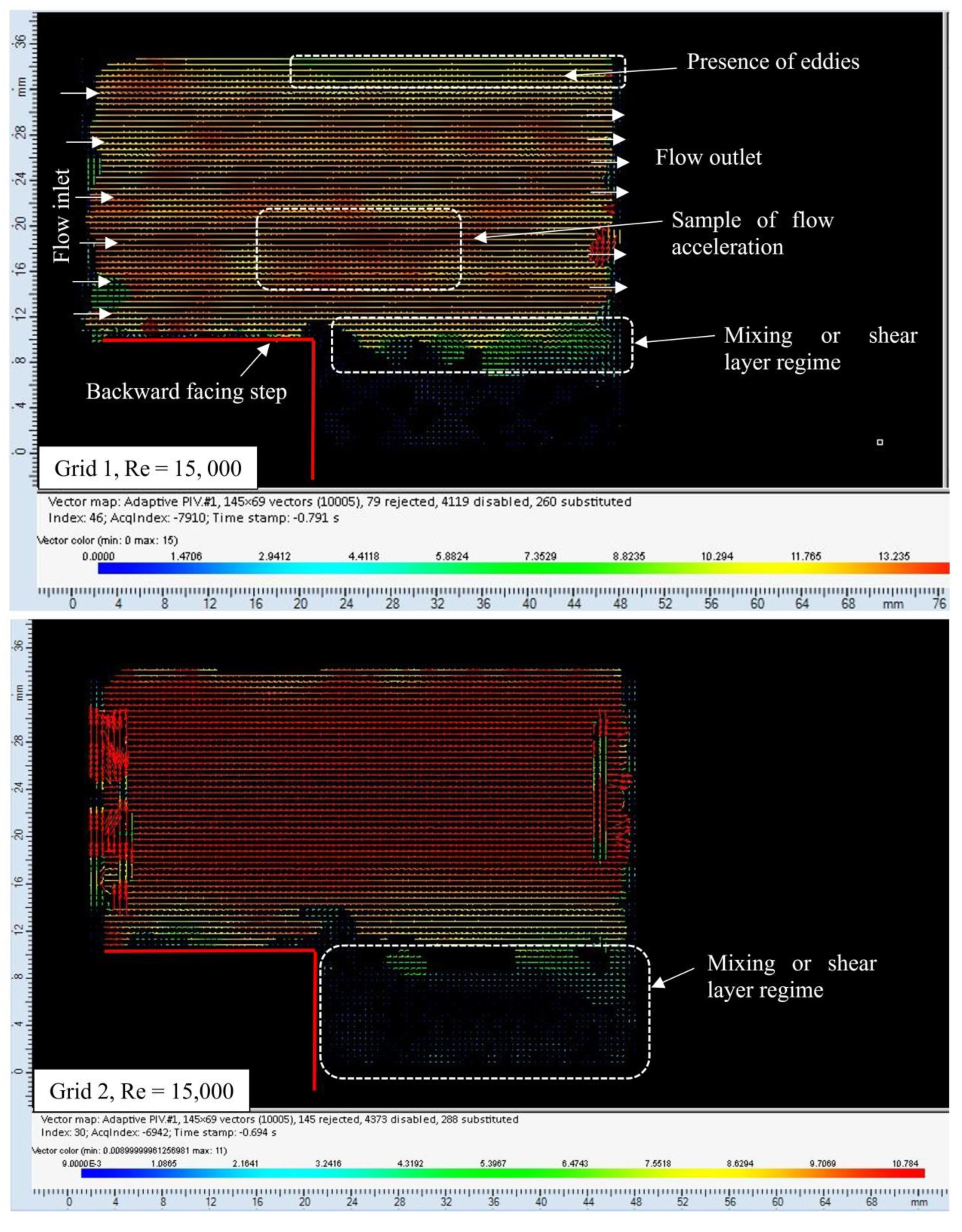
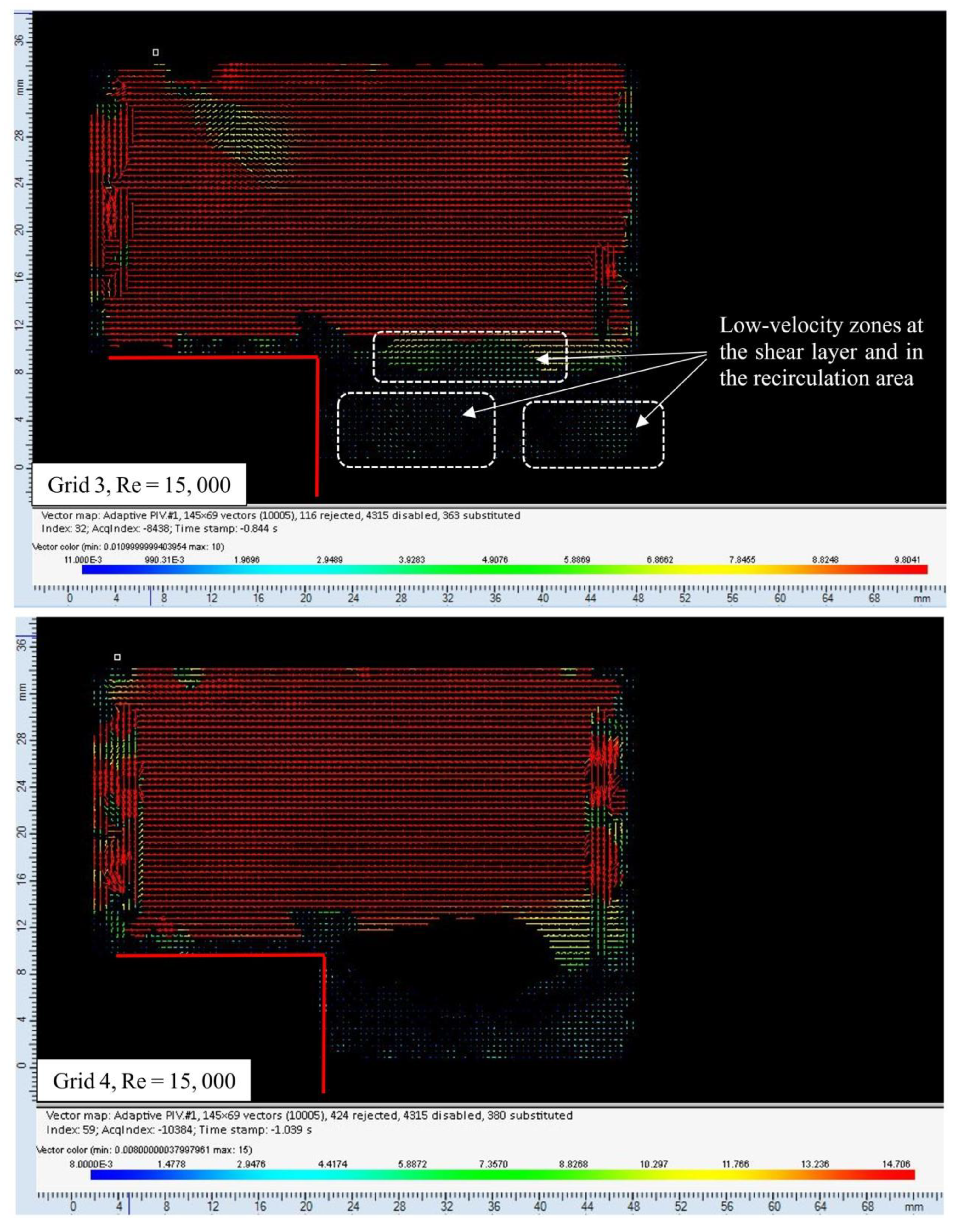
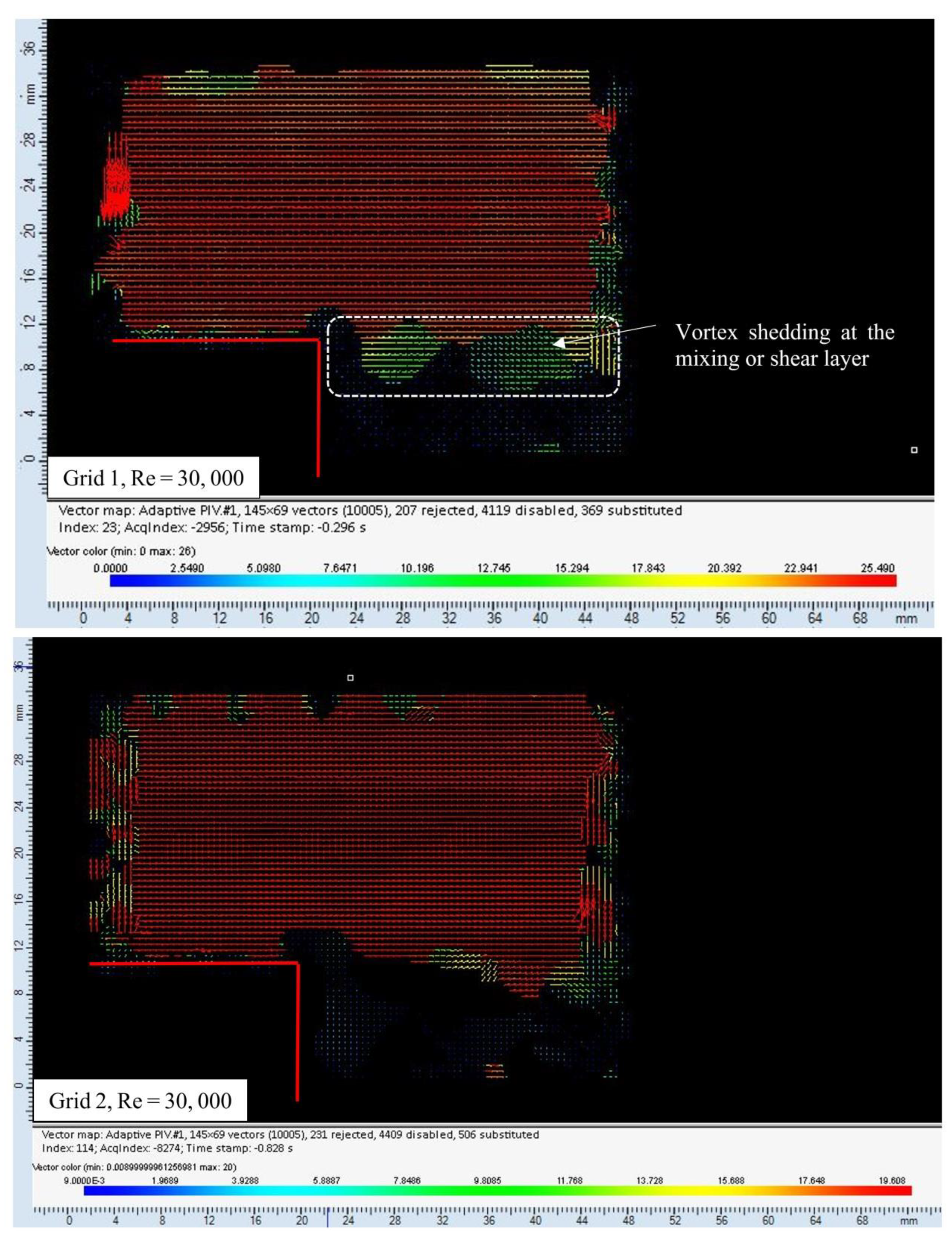
In this part, the authors aim to present the observed flow field characteristics obtained through experiments conducted with four grids at Re = 15,000 and 30,000. The velocity vector field was plotted to observe the flow events due to the backward-facing step. Figure 5 shows a dark background that was used to create a more impactful flow area and improve image contrast, resulting in clearer visualization of the flow. The grid at the combustor inlet induces homogenous turbulence in the flow because of interactions between wakes and jets behind the grid. This usually needs a significant distance downstream for the flow to become well-mixed and uniform. The authors optimized the combustor design by testing for the distance downstream that produced the best mixture. A detailed understanding of these inquiries can be found in [2,28,32]. The flow accelerated once it passed the backward-facing step, as seen in Figure 5. This happens because of the thermal dilation effects that the flow encountered downstream. The velocity contours showed the presence of a mixing or shear layer between the recirculation zone and the main flow. This layer was composed of vortices that were shed downstream from the edge of the backward-facing step. This low-speed recirculation zone helped to anchor the flame. Grids 3 and 4 had higher blockage ratios (BR), as expected flows showed fewer interacting vortices in the wake and jets of the grids, especially in the recirculation zone. At Re = 15,000 and 30,000, the occurrence of vortex shedding downstream of the sharp corner of the step was observed consistently, regardless of the presence of grids or perforated plates. The flow experienced more fluctuations at Re = 30,000 compared to Re = 15,000 due to the higher turbulence present at Re = 30,000.
In this article, the authors extracted the local velocities, vorticities, and other turbulent characteristics from the interrogation line and points distributed across the flow domain, as illustrated in Figure 5. (For a detailed understanding of the PIV data extraction, acquisition, and post-processing methods, the readers are referred to [32].) The velocities (U) and velocity fluctuations ( u ) were then calculated using Equations (3)–(5) and are presented in Figure 6. The maximum velocities of 15 m/s and 25 m/s are measured at Re = 15,000 and Re = 30,000, respectively. This indicates an increase of 5 m/s in flow velocity at both Re conditions. The maximum velocity fluctuations of 0.5 m/s and 0.25 m/s were observed for the u and v components, respectively. As expected, the perforated plate installed at the inlet of the combustor helped increase the flow velocity and flow fluctuation.
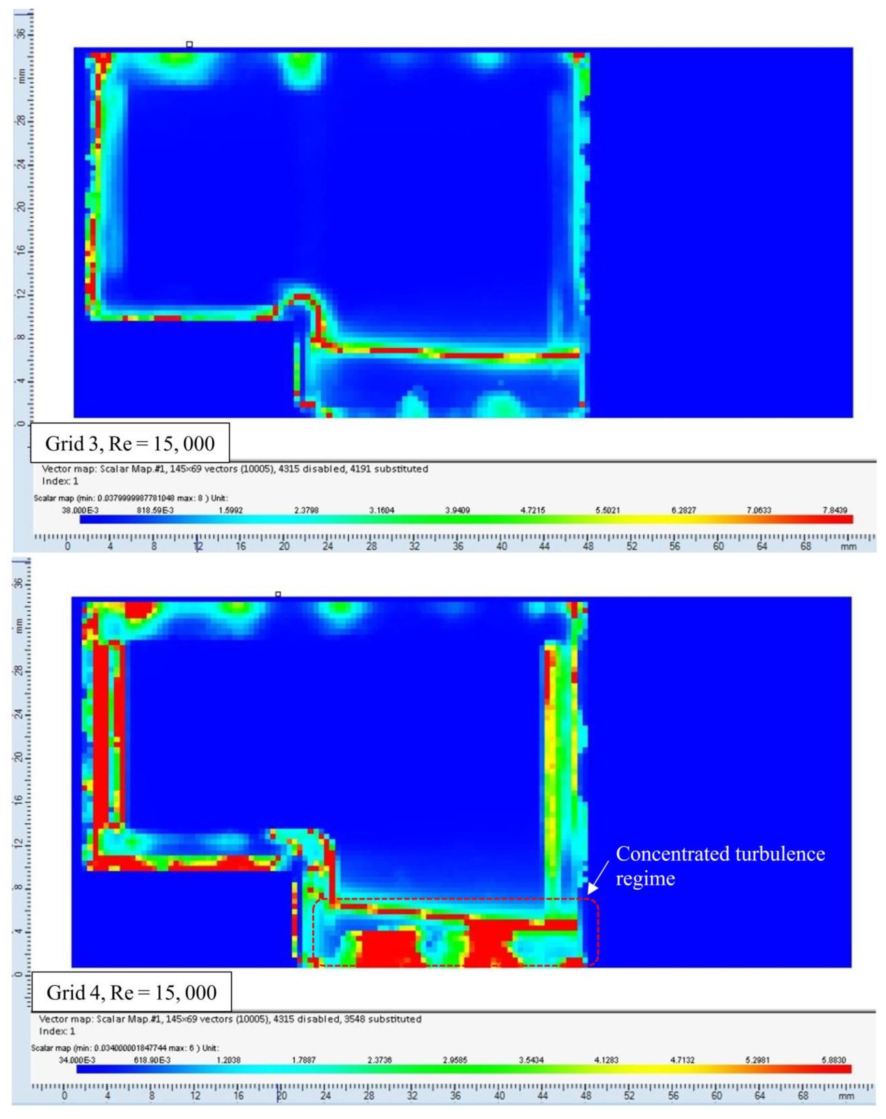
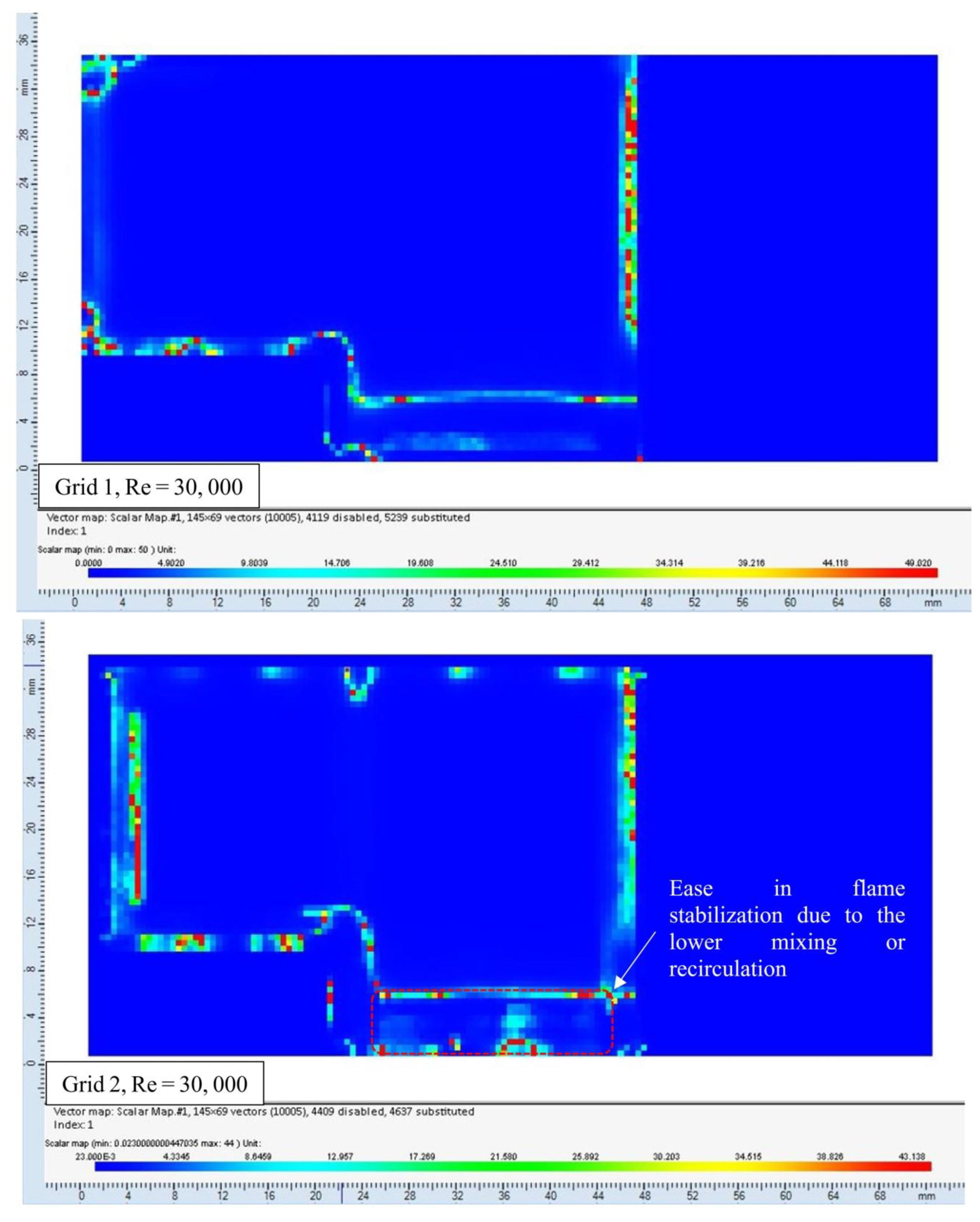
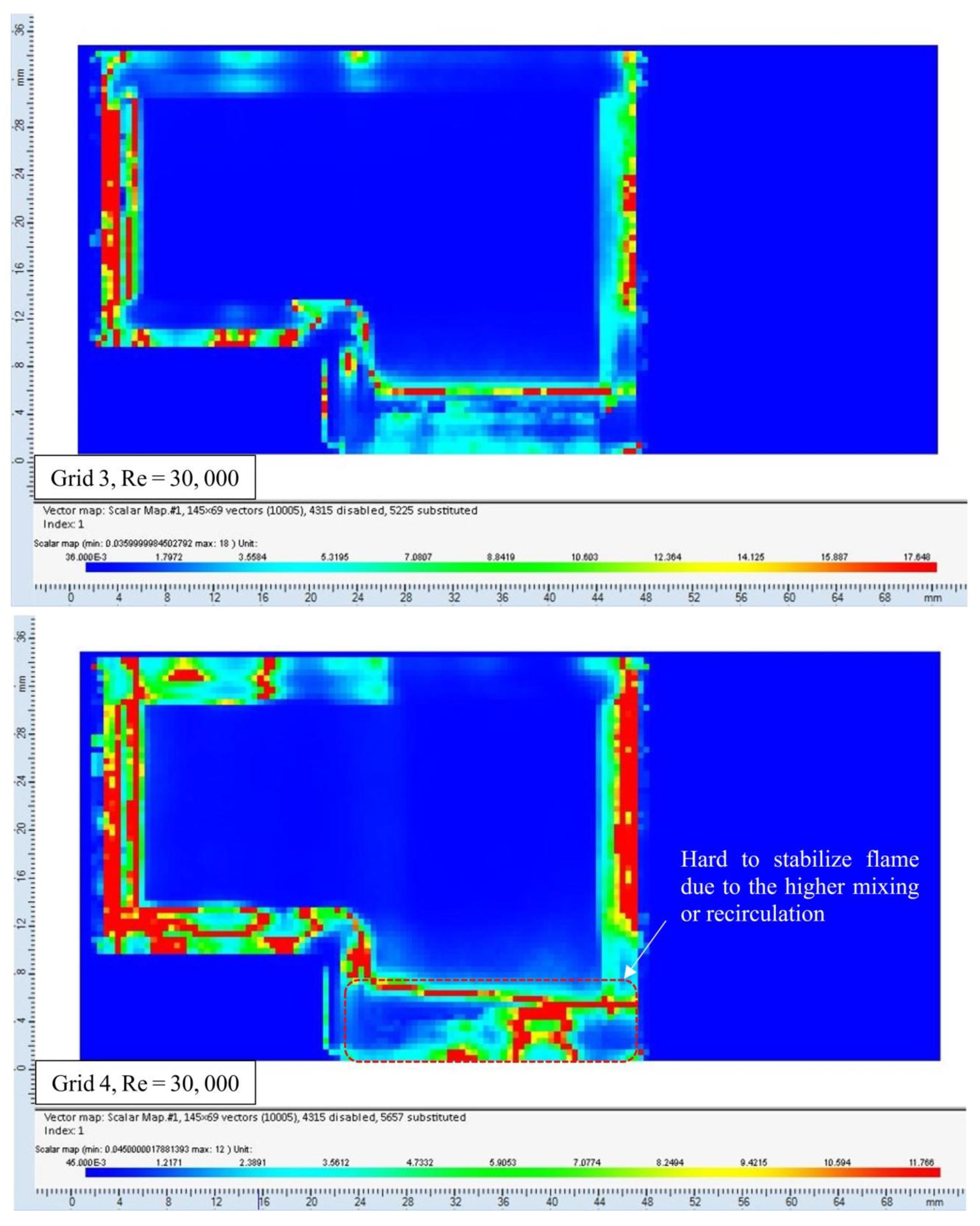
Turbulent intensity contour maps are instrumental in improving comprehension of the structure of combusting flows by visually depicting the turbulent intensity distribution throughout the combustion system. These maps are used to identify and analyze significant flow structure features, including flame stabilization mechanisms, flame front propagation, and flame extinction. By investigating variations in turbulent intensity, one can gain a deeper understanding of the intricate interactions between turbulence and combustion, ultimately facilitating enhanced efficiency, reduced emissions, and safer operation through improved design and optimization of combustion systems. With that in mind, the authors generated the turbulent intensity contour map in Figure 7. These maps show how the recirculation zone behaves at different Re and unveil how turbulence is distributed in the fluid domain. Figure 7 also helps to locate the areas of lower turbulence (reduced mixing or recirculation) and higher turbulence (higher mixing or recirculation). Figure 7 shows that when the blockage ratio is increased, the turbulent intensity increases too. Such outcomes indicate the increased amount of induced eddies in the recirculation zone at the foot of the step. In addition, when the hole diameter of the grid is increased, the turbulent intensity also changes; in both cases, increasing the hole diameter decreases the intensity. This is important because the pilot flame used to ignite the premixed methane–air mixture is located near the foot of the backward-facing step. Figure 7 shows that turbulence can influence flame anchoring or stability. It has been observed that the increase in turbulence has both pros and cons in the flame anchoring regime. While at a lower Re of 15,000, the higher turbulence has shown an improvement in flame anchoring, which is due to the better mixing of the pilot flame charge. However, when the Re is increased, a lower BR tends to help anchor the flame better compared to a higher BR. This is due to the infusion of too many eddies, which partly break up the pilot flame and causes instability. Consequently, it ultimately leads to flame blowout due to pilot flame extinction.
Grids 1 and 2 experienced less flow restriction (low BR) and thus have diffused turbulence at the recirculation zones. This aids in stabilizing the flame in the recirculation zone. On the other hand, Grids 3 and 4 exhibit concentrated turbulence. The higher flow restriction governs this behavior (high BR). Consequently, flame stabilization under Grids 3 and 4 would be challenging. The turbulence level ( I ) is high at the edge of the backward-facing step (refer to Equation (6), Table 4) and in the recirculation zone. Figure 7 also indicates how the flow fluctuation varies within the flow domain. The vortices in the shear layer (mixing layer) control the flow fluctuation at the lower part of the fluid domain. However, the overall flow fluctuation is controlled by grids and the Reynolds number. Grids 3 and 4 show more turbulent intensities compared to Grids 1 and 2 in the recirculation zone. This is again due to the higher blockage ratio of Grids 3 and 4.
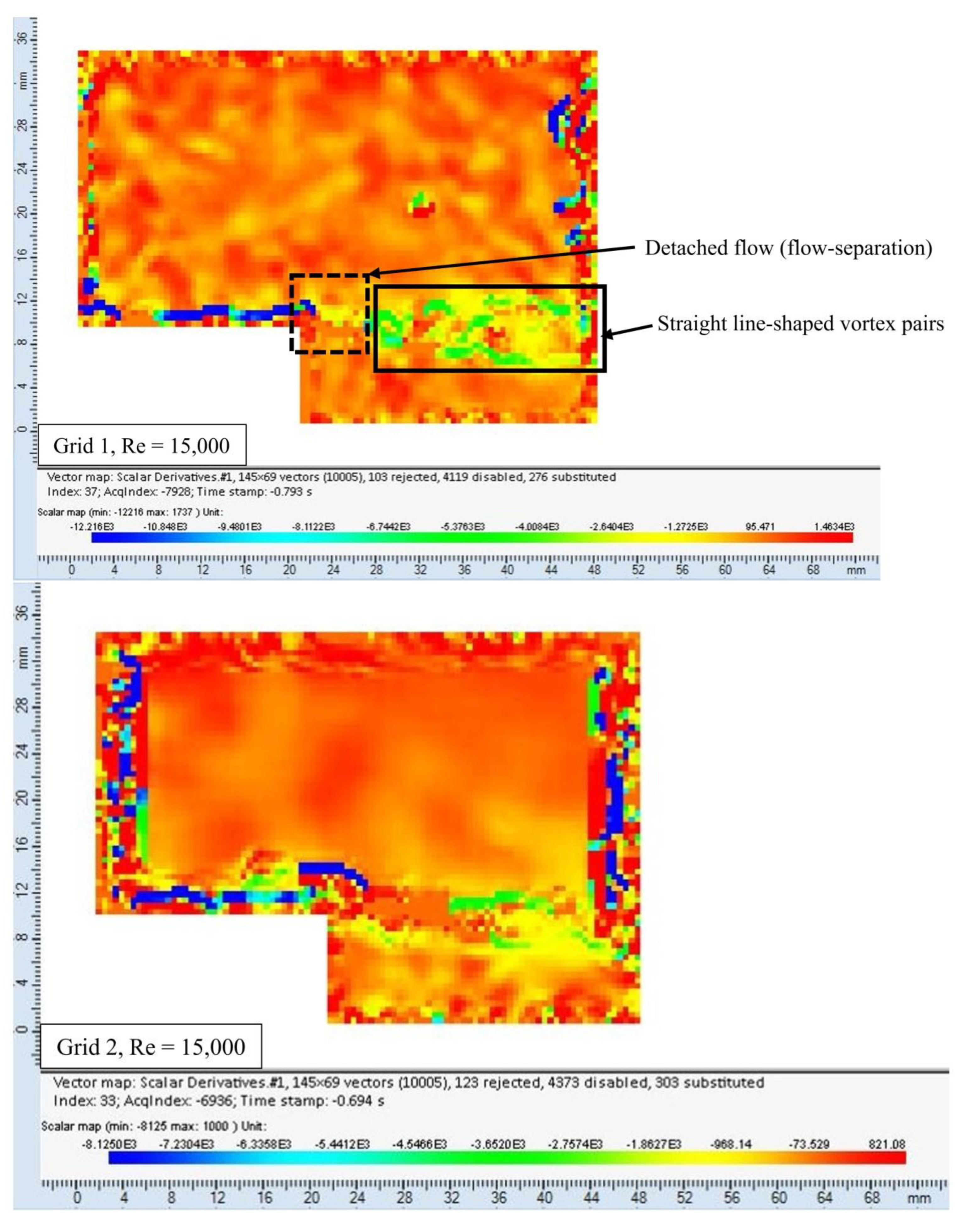
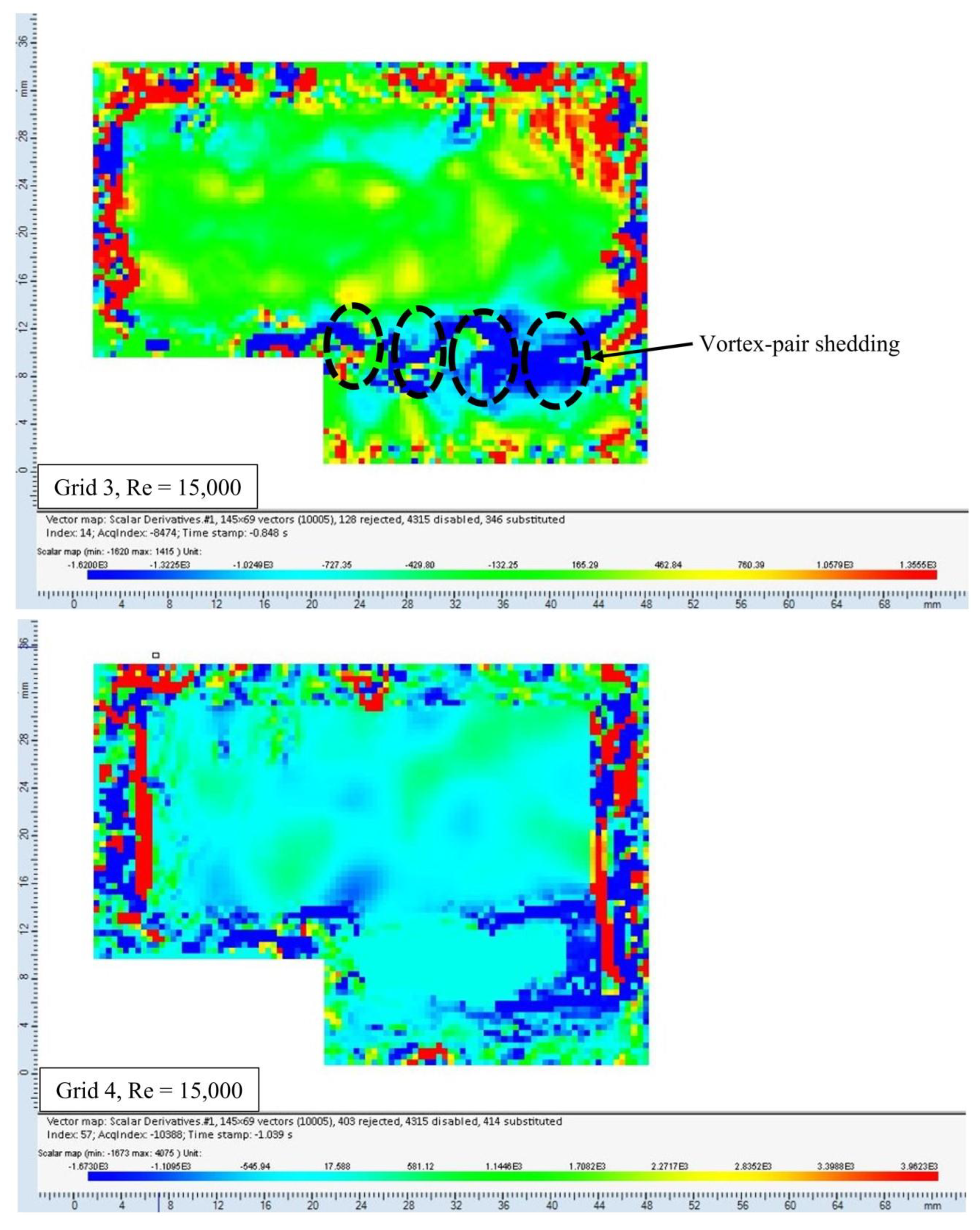
The vorticities at the edge of the step are calculated using Equations (7) and (8). Figure 8 presents the vorticity profiles. The vorticity profiles show the areas of lower and higher vorticity fluctuations. The vorticity fluctuation is very high between the 10 mm to 20 mm (the first peak) and 30 mm to 40 mm (the second peak) line distance from the reference/datum point. This is due to the significant change in velocity gradient and angular momentum in those areas, which reveals that the areas close to the step and upper part of the flow domain are susceptible to higher vorticity fluctuation. The turbulence level was found to be higher at the shear layer and is expected to have a higher vorticity value. In addition, maximum vorticity of 4100 rad/s and 50,000 rad/s was observed at Re = 15,000 and Re = 30,000, respectively. As expected, the vorticity level was high under Grids 2 and 4 (large HD), whereas it was low under Grids 1 and 3 (low HD). The PIV-derived vorticity contour maps are shown in Figure 9. These maps show how the flow was detached from the backward-facing step. Once the flow was detached, it formed low-speed recirculation zones downstream. The vorticity contours were successful in resolving the vortex pairs. The high vorticity level at the shear layers indicates that the system is designed and tested with high standards. As expected, the vorticity maps also show that the vorticity in the recirculation zone is higher under Grids 2 and 4. This is again due to the velocity gradients that are steep along the flow path under Grids 2 and 4. The y-velocity component dominated the axial component, which increased the rotation of the velocity vector. The opposite was true under Grids 1 and 3. In the colormap scales, the positive and negative values of vorticity are seen indicating the presence of both counterclockwise and clockwise vortices in the flow. Furthermore, the vorticity scale was six times higher at Re = 30,000 compared to Re = 15,000. The vortex pairs look like a straight line at Re = 30,000, whereas it looks like a spotted dot at Re =15,000. In general, the authors found that the vorticity orientation and magnitude in the contour maps were mostly controlled by velocity gradients and rotation or angular momentum within the fluid elements. The vorticities were induced through the interaction of different flow components such as shear layers, boundary layers, or swirling flows, which created regions with intense vorticity where fluid elements rotate or circulate. The presence, strength, and spatial distribution of vortices in the vorticity maps helps understand the flow dynamics under turbulent environments and guide optimization of the design of the combustor.
The PIV results showed how the flow concentration was uniformly distributed inside the combustion chamber. The flow homogeneity was achieved using the different grids at the combustor inlet. The sharp velocity gradients were seen at the backward-facing step, which aids in accelerating flame growth. The bottom wall close to the step was densely populated by small eddies. These eddies controlled the flame anchoring mechanism inside the combustor. The PIV gave a detailed statistical explanation of the flow behavior, which Table 6 lists below. However, to understand the relation of flow behavior with flame dynamics, a PLIF study was carried out.

3.2. Flame Characteristics Analysis

A flame study was conducted at Re = 15,000 (10 m/s) and Re = 30,000 (20 m/s) using the 10-kHz rate PLIF. The base image (without the flame) and the raw image (with the flame) were post-processed using the MATLAB image processing tools described previously in Figure 4. Figure 10i–iv below shows how a typical flame profile and flame edge were generated using those image processing tools.
The base image without the flame is shown in Figure 10i. This is when the igniter was off and there was no active combustion in the system. Figure 10ii is the raw image with flame when combustion occurred in the system. Figure 10iii shows the flame profiles that were generated using the MatLab-based image processing procedures listed in Figure 4. Flame profiles locate the reaction zones, show the thickness of the flame core, help to understand the flame expansion and stretching, etc. Figure 10iv shows the flame edges. The flame edges revealed the location, shape and size of flame wrinkling, and the presence of vortices, and showed how vortices infused the flame core and made the flame thin and stretch.
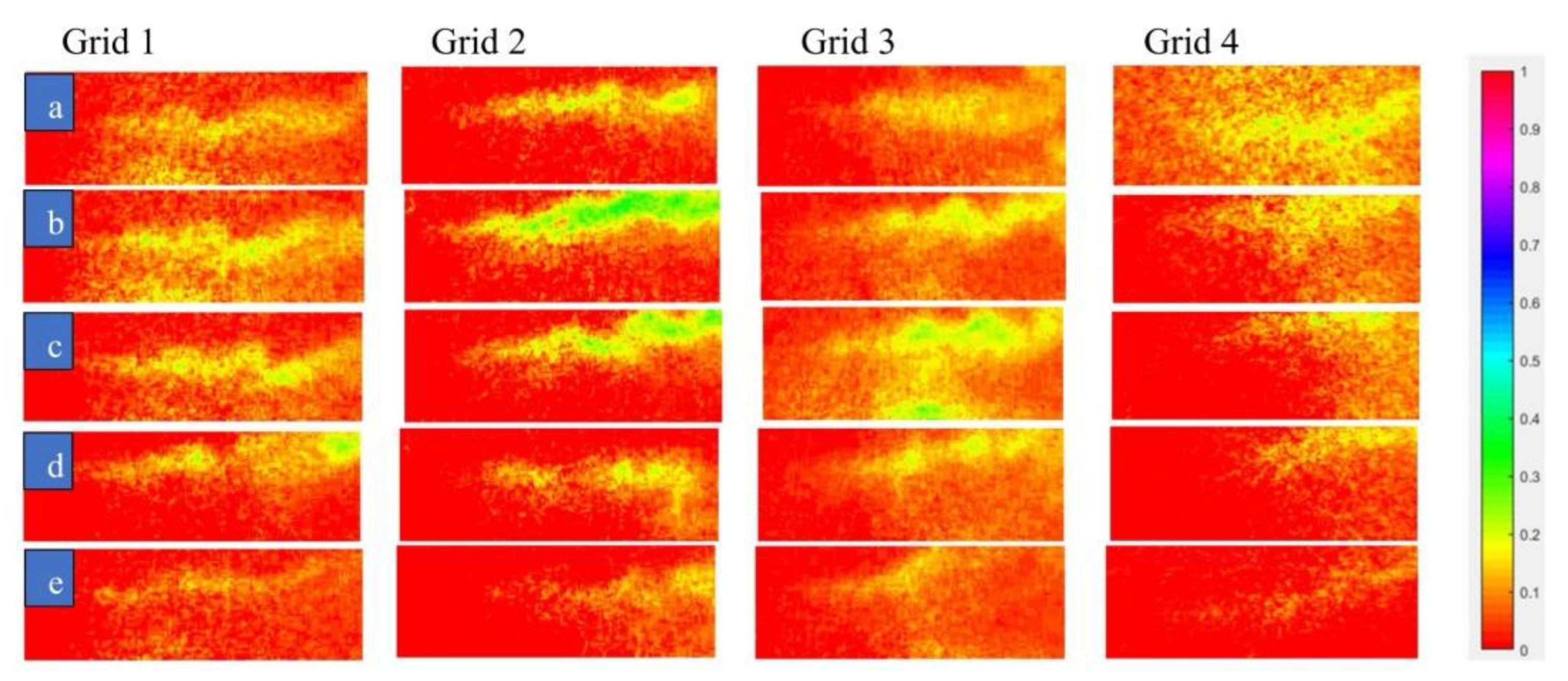
The flame progression is shown in Figure 10v. Images (a) to (e) show the progression of the flame growth from ignition initiation through blowout. Image (a) indicates the initial combustion stage; (b) shows the initiation of wrinkles; (c) reveals the formation of more wrinkles; (d) shows the breakdown of the flamelets; and (e) shows the burnout of the flamelets.
The presence of an unburned air–fuel mixture inside the burned gases and vice versa are observed in Figure 10(va). Eventually, combustion completely burns all the air–fuel mixture. The authors studied the recess length and made sure that the mixing, residence time and air–fuel ratio were adequate for the complete combustion of methane air. There were different levels of turbulence in the flame. Additionally, the flame profiles show irregularly shaped wrinkles (handgrip-like structures), see Figure 10(vb). The wrinkles continued to form as the flame progressed downstream as shown in Figure 10(vc). The flow fluctuation, thermal instabilities caused by buoyancy and expansion, and local flame viscosity controlled the flame wrinkling. The turbulent and velocity scales—for example, velocity fluctuation (u’) and turbulent length-scale (LT)—generated high compressive forces in the flame, leading to accelerated flame–flame interactions. This interaction enhanced the reactant-product pocket formation rate [36], causing many finger-shaped wrinkles to form in the flame. It also causes to change in flame thickness, (δL) and flame expansion.
After the flame wrinkling, the next event is called the breakdown of the flamelet or pinch-off event Figure 10(vd). The large-scale fluid structures caused the reaction zone to shatter, leading to flamelet detachment from the edges. Local velocity fluctuations and thermal diffusion further accelerated pinch-off events. Near the bottom wall, at a distance downstream, the breakdown (pinch-off) event accelerated. This was due to the infusion of small eddies into the flamelet regime. These small-scale, semi-detached, burned gases sometimes reach self-ignition temperature and start to burn out or disappear. This is commonly known as a burned-out event Figure 10(ve). The pinch-off and burnout events occurred spontaneously and were controlled by parameters such as pressure, turbulent length scale, and velocity fluctuation. Flame profiles observed in this research work are very thin (thin reaction zone); therefore, all the images presented below are intensified and zoomed in for better interpretation and visualization.
The authors conducted a qualitative analysis of flame behavior in this article. Therefore, the authors combined all the images together and present them here so that an overall understanding of how flame propagates and interacts under different grids and Reynolds numbers could be made. First, thin fluctuating flame profiles are seen in Figure 11, Figure 12 and Figure 13. Additionally, the flame width increased as it moved downstream. This is referred to as flame broadening. The local flame diffusivity increased due to the enhanced heat and mass transfer imparted to the reaction zone by the turbulent eddies. This caused the flame’s core structure (width) to increase. As reported in [37,38], these large-scale eddies and wrinkles should enhance the reactant burning rate, flame burning area, and flame propagation speed. As the velocity increased downstream, high-energy fluid structures formed. This increased the turbulent eddy diffusivity and suppressed the strain rate effect, influencing flame stretching. Broadened flame structures were observed under all grids.
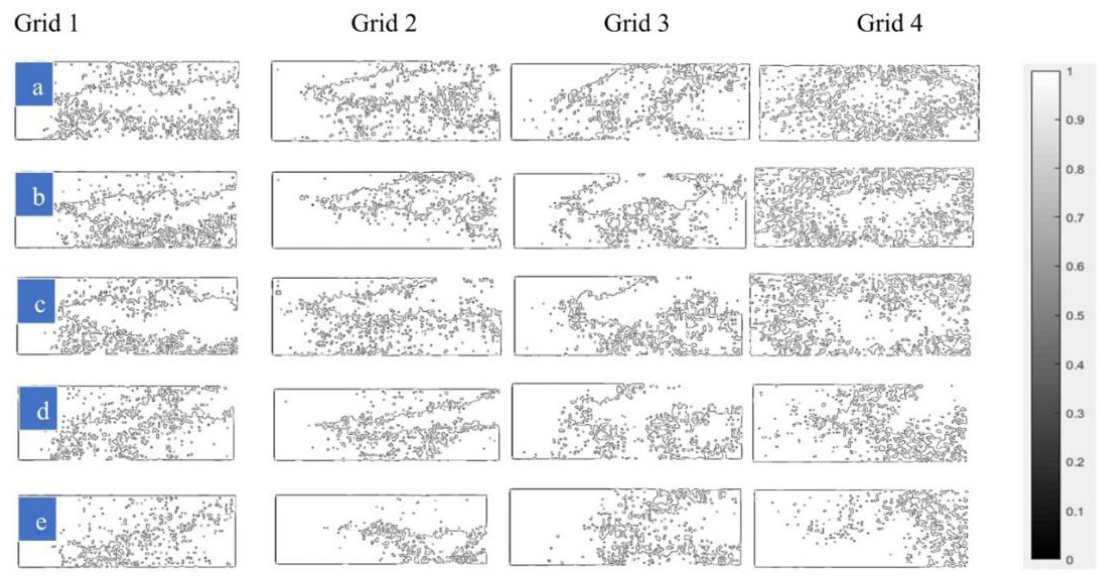
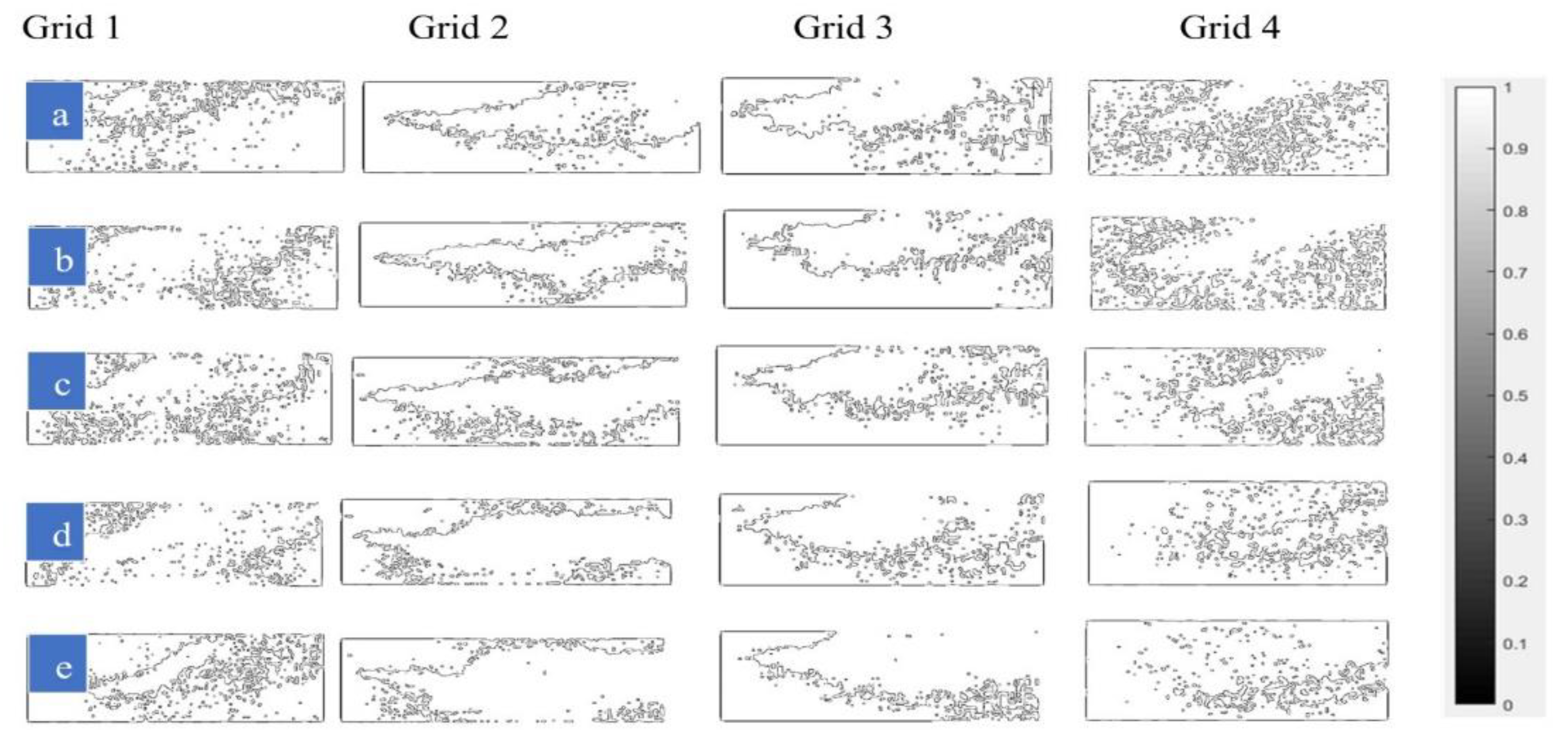
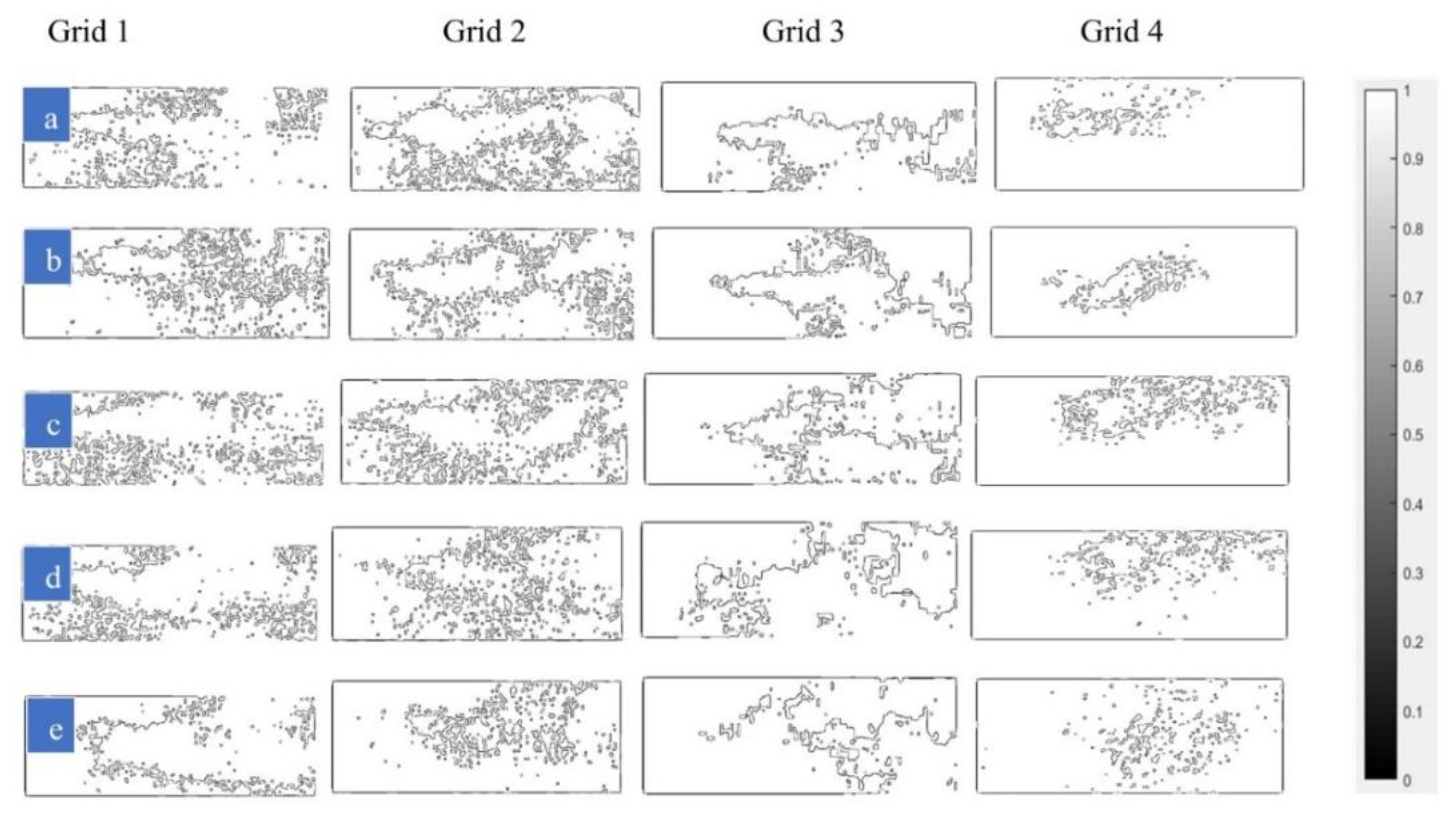
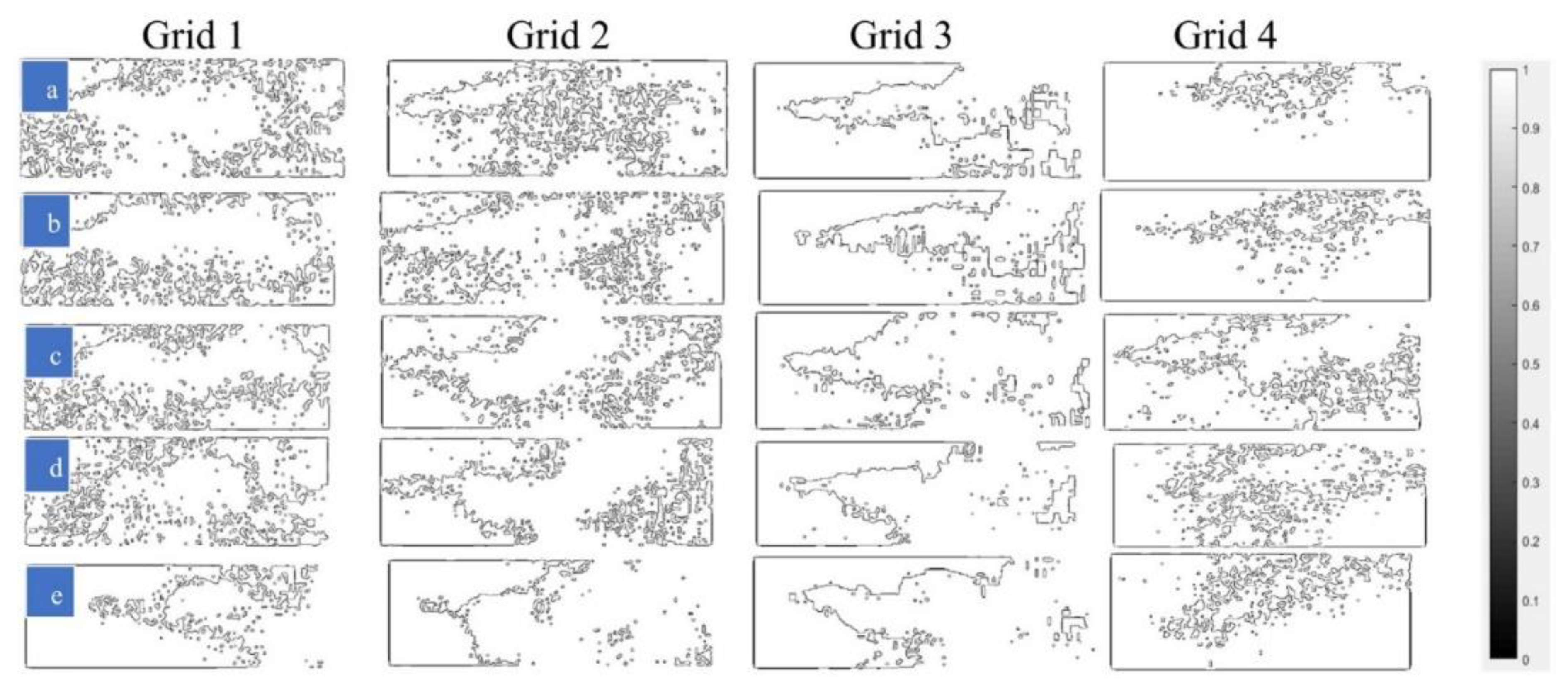
The effect of grids on flame characteristics has been studied (see Figure 11, Figure 12 and Figure 13). The flame profiles under Grids 1 and 3 had more wrinkle growths. This was due to the higher change in thermal diffusion and viscosity of the flame under those grids, as also reported in [5]. However, there is less presence of large-scale wrinkles in the flames under those grids. Thus, flame stretching and flame width are less under Grids 1 and 3. The opposite is true for the flame under Grids 2 and 4 (see Figure 11, Figure 12 and Figure 13).
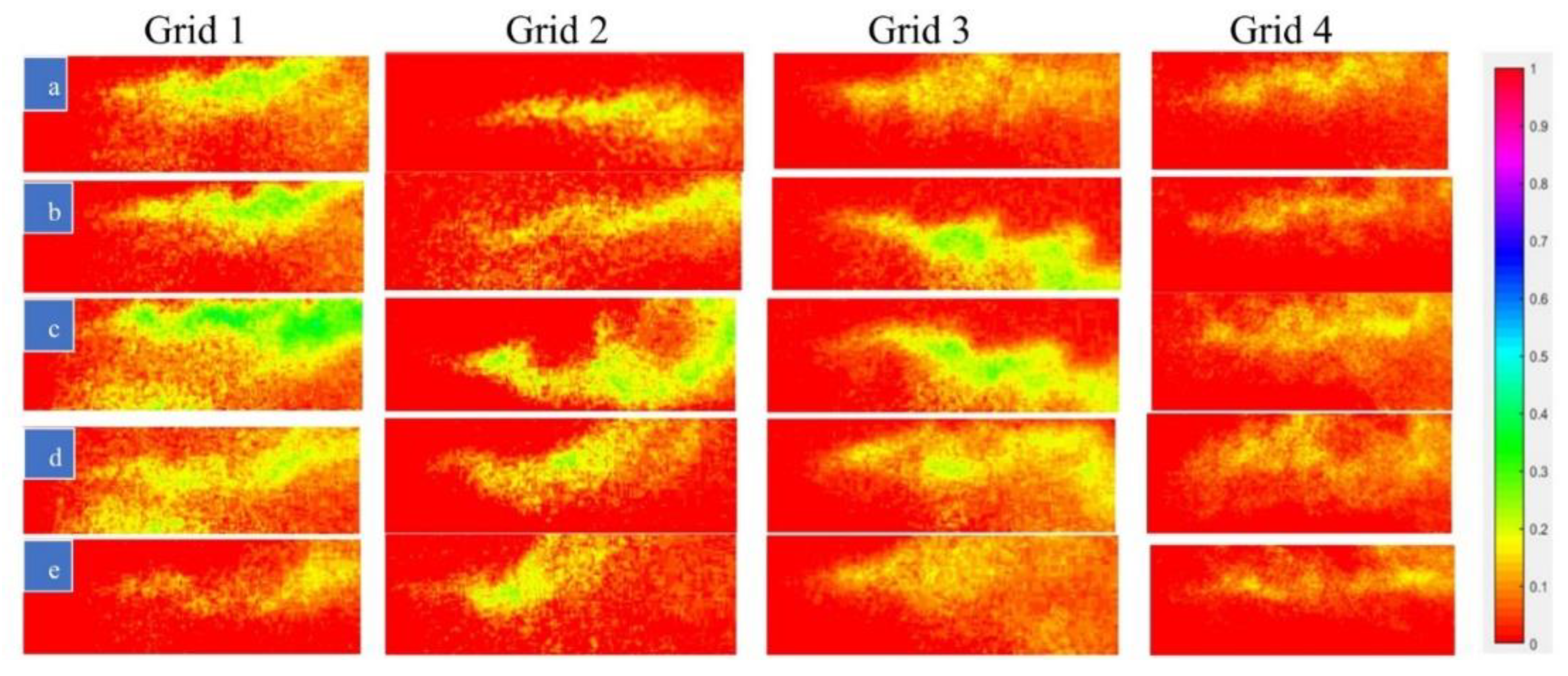
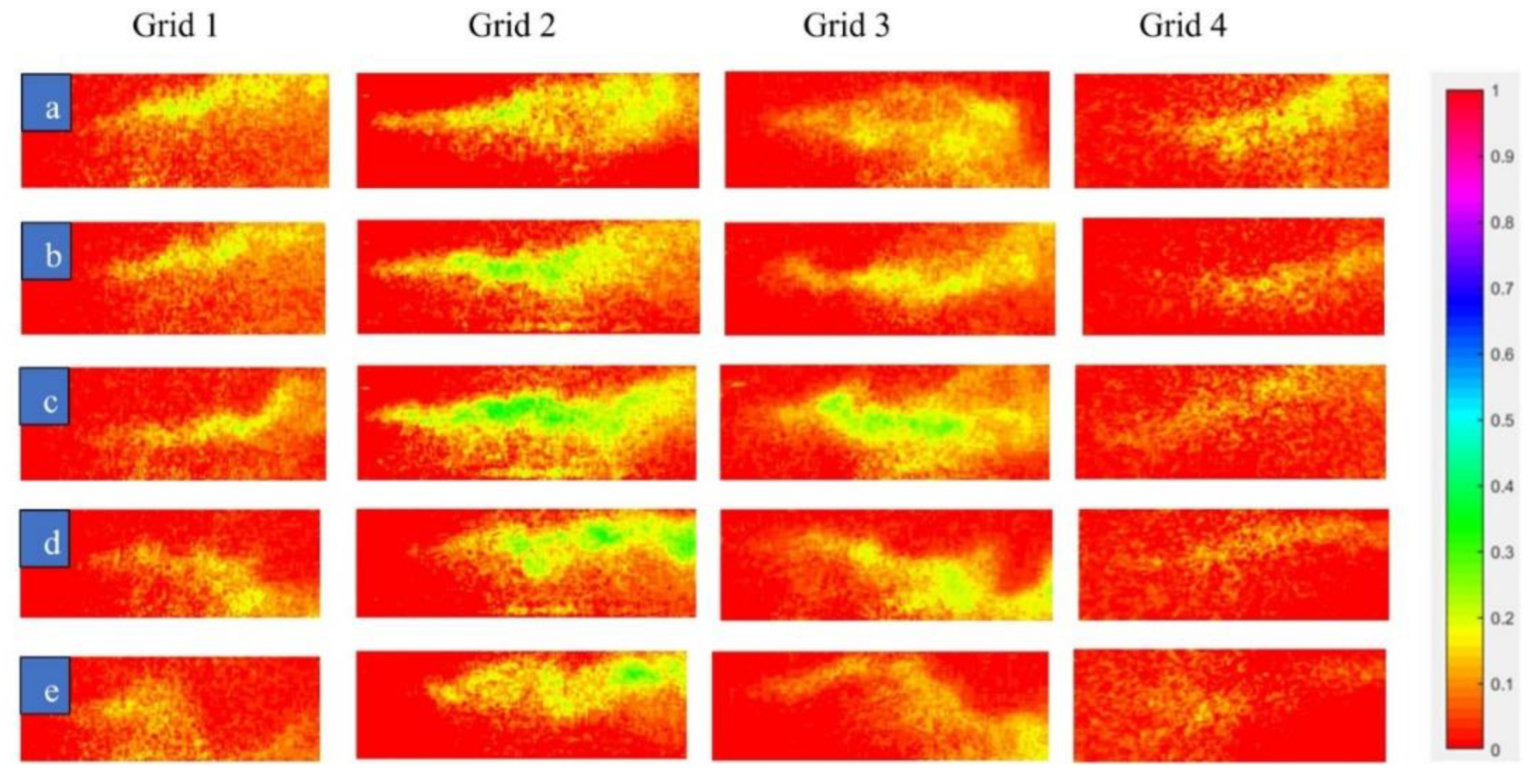
The effect of two different Reynold’s numbers on flame evolution has been studied. The flame expansion was faster at Re = 30,000 (20 m/s) (Figure 14, Figure 15 and Figure 16) compared to Re = 15,000 (10 m/s) (Figure 11, Figure 12 and Figure 13). The local flame strain rate increased with the increase in flow velocity. This strain tries to suppress flame growth. However, higher-order turbulence at higher Re aided in overcoming this challenge. Similar research on flame expansion rate is reported in [39]. Additionally, at Re = 30,000, the flow mixture velocity (20 m/s) dominated over turbulent eddy viscosity ( u l o   o r   u ƞ ) , see Table 6. Therefore, the flame front broadened in both axial and radial directions and allowed the small eddies to infuse into the flame core (see Figure 14, Figure 15 and Figure 16).
The flame wrinkling (irregularly shaped edges) was higher at Re = 30,000 compared to Re = 15,000. This was because a large number of small-scale eddies and higher flame instabilities (mostly the flame fluctuation) were present at Re = 30,000 (see Figure 14, Figure 15 and Figure 16).
The effect of the equivalence ratio (Φ) on flame propagation was also investigated. The reactant-product pocket formation rate increased with fuel loading as Φ increased. Therefore, at Re = 30,000 and Φ > 1, the flame wrinkling rate is maximum. Additionally, the pinch-off and burnout rates were higher at Re = 30,000 (Figure 14, Figure 15 and Figure 16d,e). The same finding is also reported in [40]. In addition, the flame stretching rate was found to be higher at Re = 30,000. This was due to the large-scale wrinkles that interacted with each other and formed new wrinkles along the flame edges. As a result, the flame stretched across those wrinkles. The opposite is true for Re = 15,000.
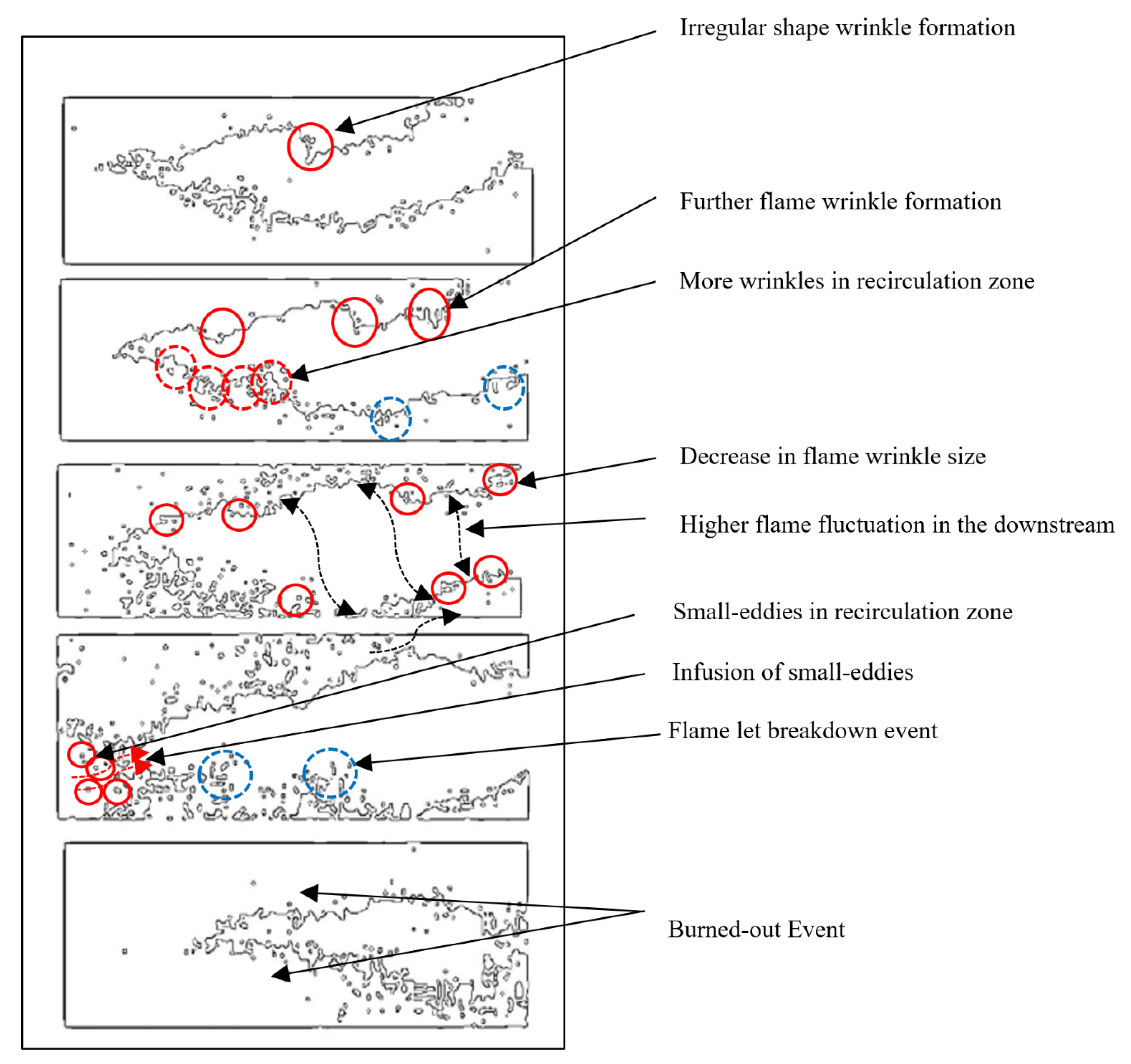
The flame profiles alone do not offer a comprehensive understanding of flame behavior. To gain more detailed insights into crucial flame characteristics such as flame boundaries and wrinkles, the authors utilized MATLAB image processing tools with in-house coding (see Figure 4) and generated corresponding flame edges (See Figure 17).
Figure 17 shows how the wrinkle initiated and grew with time. It also shows how the wrinkles changed their shape and size from ignition through the blowout. The wrinkles have an irregular shape with handgrip-like structures. Wrinkle shape does not change, but wrinkle size changes throughout the flame evolution (ignition to burnout). The flame edges show the presence of many small eddies in the recirculation zone. The same behavior is noticed in the PIV analysis. This validates the role of the backward-facing step in flame anchoring.
The flame had more fluctuation downstream (see flame edges under Figure 18, Figure 19, Figure 20, Figure 21, Figure 22 and Figure 23). Flame growth was mostly controlled by flame wrinkling and turbulence. The flame was continuous and had no flame extinction for the Re conditions considered in this paper. Wrinkle formation (Figure 18, Figure 19, Figure 20, Figure 21, Figure 22 and Figure 23b) was adequate to maintain a continuous flame and not too extreme. The flame edges also showed how the small eddies infused into the flame core and the flamelet (small-scale flame eddies) detached and reattached to the flame core. These events were more common at Re = 30,000 (see Figure 21, Figure 22 and Figure 23b–d) due to the increase in flame displacement rate. In other words, vorticity-strain rate effects were higher at Re = 30,000.
The flame was thinner at Re = 30,000 and wider at Re = 15,000 (see Figure 18, Figure 19, Figure 20, Figure 21, Figure 22 and Figure 23). This could be justified by the PIV-derived data presented before. The velocity contours (previously presented in Figure 5) show that the local flow velocity was high and residence time was low across the shear layer at Re = 30,000. Consequently, the flame did not have enough time to expand laterally and became thinner. The opposite is true at Re = 15,000. The flame edges also show that the flame wrinkling rate is higher under Grids 1 and 3, whereas pinch-off and burnout rates are higher under Grids 2 and 4. The same behavior is noticed in the flame profiles reported earlier in Figure 11, Figure 12, Figure 13, Figure 14, Figure 15 and Figure 16. A similar observation is reported in [41,42].
The flame profiles (Figure 11, Figure 12, Figure 13, Figure 14, Figure 15 and Figure 16) and flame edges (Figure 18, Figure 19, Figure 20, Figure 21, Figure 22 and Figure 23) presented above show that the CH layer (reaction zone layer) is thinner at both Re conditions. However, the CH layer thickness increased slightly downstream. This happens because the turbulence dominated over the strain rate downstream. The CH layer resembled both flamelet-like and diffuse-like structures. The authors believe that the flame signal detected by the C-X CH PLIF was not entirely the CH signal: there might be a presence of some CH * chemiluminescence. This is why in some cases the flame profiles looked diffuse. The authors completed some preliminary iterations on methane–air premixed reacting flames using the CH PLIF. The authors believe that there are still many questions and issues that need to be addressed in future research iterations. For example, the CH filter and the operating parameters of the camera intensifier units such as gate pulse width and gate exposure/opening time need to be re-tuned according to the higher test operating conditions. Additionally, the wavelength tuning for the C-X band of CH PLIF should be further examined. The flame edges showed that the CH signal decreased with the increase in Re. The authors will also consider this in the next research iteration. The authors are recommending preheating the reactants at elevated temperatures for higher Re combustion tests. The incorporation of higher-order alkaline into the reactants might resolve this issue. However, a series of experimental tests and more theoretical research must be conducted before making any conclusion on this issue.
The effect of equivalence ratios (Φ) on flame evolution was investigated using the flame profiles and edges reported above. Data from the temperature sensors (k-type) indicate that the chamber heat release rate increased with the increase in fuel loading, Φ. This is because the combustion radical fraction and their reaction rates increase with Φ. The same behavior is reported in [1,5,43]. The authors used a series of temperature sensors (non-intrusive) on the combustor walls. The temperature sensors sensed the wall face temperature during the combustion. After that, the LabView tool generated the associated heat release rate from the combustor walls, exhaust chamber, and cooling chamber. This information has already been published by two of the co-authors of this paper, [28,32].
The flame reaches the maximum static temperature (~2200 K) at Φ =1.2. Therefore, according to the literature [6], the flame surface consumption rate, flame surface area, and flame length should increase at Φ > 1. Additionally, the flame surface area directly relates to the flame burning velocity and flame front curvature. Thus, at higher Φ, the flame burning area and flame front curvature should increase [3,31,43]. The flame fluctuation (less radical kinetics) is less for the lean mixture (Φ = 0.8). A moderate level of flame fluctuation is seen at Φ = 1.2 (see Figure 18, Figure 19, Figure 20, Figure 21, Figure 22 and Figure 23). However, this small fluctuation does not affect the flame stability studied in this paper, as also reported in [4]. The authors believe that more tests at variable Φ need to be conducted to conclude these predictions.

3.3. Flame Regime Plot

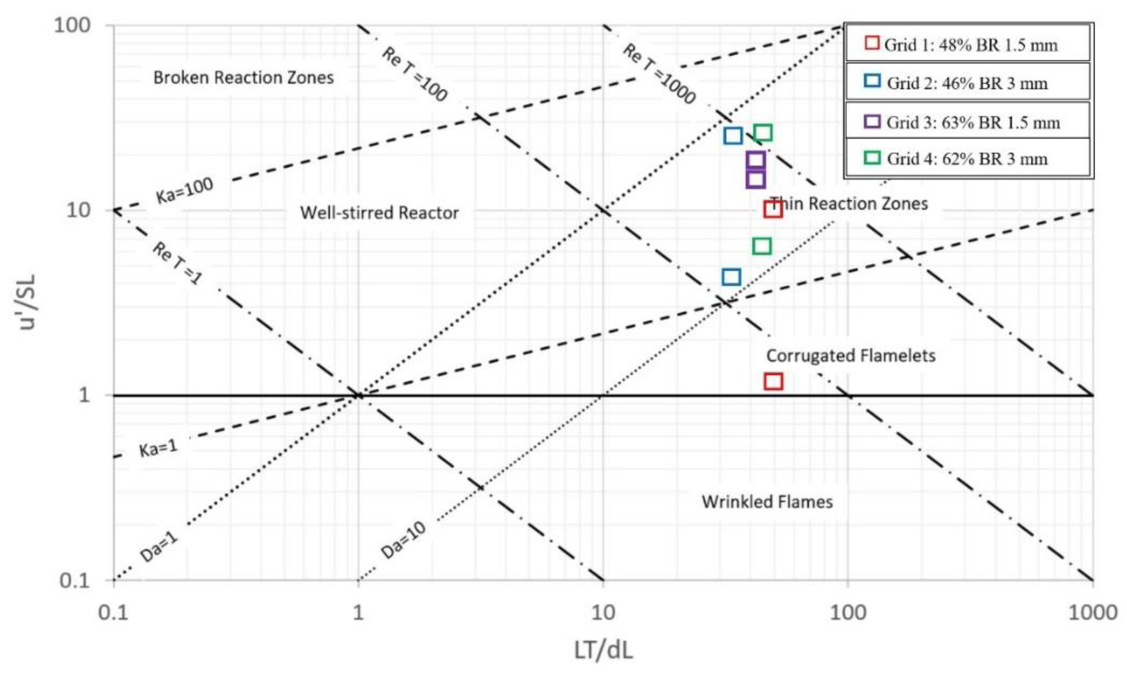
The laminar flame characteristics such as laminar flame speed and laminar flame thickness used in this paper are extracted from the papers published by two of the co-authors of this article, [28,32]. Information regarding the laminar flame characteristics is also well-reported in the literature [44,45]. The flow characteristics were extracted using the PIV results reported in this paper. All this information was used to locate the flame on the Borghi–Peters diagram (see Figure 24). The PIV results and flame characteristics used to locate the flame regime boundaries are summarized in Table 6 and Table 7.
The thickened flame (thin reaction zone) was observed at all flow conditions except the flame under Grid 1 at Re = 15,000 (Figure 24). At this specific condition, the flame falls in the corrugated flamelet regime. This happened because of the velocity fluctuation relative to laminar flame speed ( u S L ) was low under this specific condition. The thickness of small-scale eddies (Kolmogorov scales, ƞ) was less than the flame thickness ( δ ). The small-scale eddies were infused into the flame and made the reaction zone thinner. Therefore, the reaction zone was much thinner at Re = 30,000 than Re = 15,000. The flame did not fall in the broken reaction zone so there was no flame break up. It is hypothesized that the flame wrinkling was not severe and flame stabilized at both flow conditions.
The flame location on the Borghi–Peter diagram gives some insight into the flame behavior at different turbulence levels. The flame lies on the top of the thin reaction zone under Grids 2 and 4 (see Figure 24). This means that the Kolmogorov time scale is less than the chemical time scale (higher Ka value) and more flamelet breakdown should be expected under Grids 2 and 4. On the other hand, the flame fell at the core of the thin reaction zone under Grids 1 and 3. Therefore, the reaction rate dominated over the diffusion rate (lower Da value) and more flame wrinkling should be seen under Grids 1 and 3. This is exactly what the authors noticed from the flame profile and flame edges reported previously in this paper.

4. Conclusions

The current study reports the flow and flame characteristics in extreme turbulence environments using 10 kHz PIV and 10 kHz PLIF. The premixed methane–air flow inside a small-scale windowed combustor was considered for this study. Different flow conditions (Re = 15,000 (10 m/s), Re = 30,000 (20 m/s)), fuel concentrations (Φ = 0.8, 1.0, and 1.2) and grid turbulators (grids) (BR = 46%, 48%, 62% and 63%) were used for flow and flame study. PIV results show that the flow turbulence increased downstream due to the drastic change in the flow passage after the backward-facing step. The turbulence was higher in the shear layer. Perforated stainless steel (SS) plates, namely grid turbulators (grids), created isotropic homogeneous turbulence inside the combustor. The backward-facing step helped in small eddy formation, flow acceleration, and flame stabilization. The small HD grids (Grids 1 and 3) produced continuous fluid structures and comparatively less turbulence in the flow. On the other hand, large HD grids (Grids 2 and 4) created large-scale fluid structures and higher velocity fluctuation ( u ) in the flow. The flame front study was carried out using C-X CH PLIF at a wavelength of 314.415 nm. The higher laser absorption and emission coefficients gave outstanding flame profiles at this wavelength. The reaction rate was faster than the diffusion rate under Grids 1 and 3 (lower Da value). This was due to the presence of high-pressure fluctuations and thermal instabilities in the flame. Thus, the flame wrinkling was higher under Grids 1 and 3. The turbulence intensities (I) and flame thermal diffusivity are higher under Grids 2 and 4 (higher Ka value). Accordingly, the pinch-off and burnout rates are higher under these grids. The PIV and PLIF study revealed that the Re, turbulent length scales ( L T ), and wrinkling mostly controlled flame evolution. The flame growth rate was faster at Re = 30,000 compared to Re = 15,000 due to the higher velocity fluctuations and thermal instabilities at Re = 30,000. The flame edges showed that the flame had both flamelet and diffuse-like structures. Further, the flame had irregularly shaped wrinkles and the size of those wrinkles decreased with time as the flame progressed downstream. Flame edges justified the infusion of small eddies into the flame core; this eventually helped in flame anchoring. Flame expansion and flame stretching are higher at Re = 30,000 compared to Re = 15,000. The flame mainly fell in the thin reaction zone (thickened flame regime) except for one that fell in the corrugated flame regime. However, the flame was close to the broken reaction zone. For this, the authors are recommending taking extra precautions in future high-speed combustion tests. Additionally, the authors are aware that the flame signal detected by the C-X CH PLIF was not entirely the CH radical signal. Some CH * chemiluminescence might be present in the flame. This is a preliminary study where the authors implemented the CH PLIF in the high-pressure turbulent reacting premixed combustion environment. The authors want to conduct more studies to see how the C-X CH filter and camera intensifier properties such as gate pulse width and gate exposure/opening time play a role in flame image detection.

Author Contributions

Conceptualization, A.C.; methodology, M.A.H., M.N.A.I., M.D.L.T. and A.A.Z.; software, M.A.H. and M.N.A.I.; validation, M.A.H.; formal analysis, M.A.H.; investigation, M.A.H.; resources, A.C.; data curation, M.A.H., M.N.A.I., M.D.L.T. and A.A.Z.; writing—original draft preparation, M.A.H.; writing—review and editing, M.A.H.; visualization, M.A.H., M.N.A.I., M.D.L.T. and A.A.Z.; supervision, A.C.; project administration, A.C.; funding acquisition, A.C. All authors have read and agreed to the published version of the manuscript.

Funding

This research work was supported by the National Aeronautics and Space Administration (NASA) (award No(s) NNX09AV09A) and the Army Research Office (ARO) (award No(s) W911NF-13-1-0156).

Data Availability Statement

Source data and other raw data are available from the corresponding author upon request.

Acknowledgments

The authors would like to thank former graduate research assistants at the Aerospace Center at UTEP: Martin Alejandro De La Torre (currently Engineer, Blue Origin, FL, USA) and Arturo Acosta-Zamora (currently Engineer, Intel, OR, USA) for their contribution to preliminary research work. The authors also would like to thank the faculties and staff of the Aerospace Center at UTEP for their supervision and support.

Conflicts of Interest

The authors declare no conflict of interest.

Nomenclature

PLIFlanar laser-induced fluorescence
PIVParticle image velocimetry
HDHole diameter
BRBlockage ratio
CCDCharged couple device
ΦEquivalence ratio
xMole fraction
ω ¯ Vorticity, curl of mean velocity
ωzVorticity in the z-direction, computed from the velocity gradients
𝝏 U 𝝏 y X-velocity gradient in the Y direction
u Velocity fluctuation
ITurbulent intensity
DaDamkohler number
KaKarlovitz number
SLLaminar flame speed
δLLaminar flame thickness
ReReynolds number
R e T Turbulent Reynolds number
LTTurbulent length scale
uRMSRMS of u velocity, computed from the velocity variance
vRMSRMS of v velocity, computed from the velocity variance
FOSFactor of safety

References

  1. Bobba, M.K. Flame Stabilization and Mixing Characteristics in a Stagnation Point Reverse Flow Combustor; Georgia Institute of Technology: Atlanta, GA, USA, 2007. [Google Scholar]
  2. Hossain, M.A. Design of a High Intensity Turbulent Combustion System; The University of Texas at El Paso: El Paso, TX, USA, 2015. [Google Scholar]
  3. Sadiq, A.M.; Sleiti, A.K.; Ahmed, S.F. Turbulent Flames in Enclosed Combustion Chambers: Characteristics and Visualization—A Review. J. Energy Resour. Technol. 2020, 142, 080801. [Google Scholar] [CrossRef]
  4. Periagaram, K. Determination of Flame Characteristics in a Low Swirl Burner at Gas Turbine Conditions through Reaction Zone Imaging; Georgia Institute Technology: Atlanta, GA, USA, 2012. [Google Scholar]
  5. Wang, Z.; Bai, Z.; Yu, G.; Yelishala, S.; Metghalchi, H. The Critical Pressure at the Onset of Flame Instability of Syngas/Air/Diluent Outwardly Expanding Flame at Different Initial Temperatures and Pressures. J. Energy Resour. Technol. 2019, 141, 082207. [Google Scholar] [CrossRef]
  6. Allison, P.M. Experimental Characterization of Combustion Instabilities and Flow-Flame Dynamics in a Partially-Premixed Gas Turbine Model Combustor; The University of Michigan: Ann Arbor, MI, USA, 2013. [Google Scholar]
  7. Troiani, G.; Lapenna, P.E.; Lamioni, R.; Creta, F. Self-wrinkling induced by Darrieus-Landau instability in turbulent premixed Bunsen flames from low to moderately high Reynolds numbers. Phys. Rev. Fluids 2022, 7, 053202. [Google Scholar] [CrossRef]
  8. Lapenna, P.E.; Troiani, G.; Lamioni, R.; Creta, F. Mitigation of Darrieus–Landau instability effects on turbulent premixed flames. Proc. Combust. Inst. 2021, 38, 2885–2892. [Google Scholar] [CrossRef]
  9. Chaudhuri, S.; Saha, A.; Law, C.K. On flame–turbulence interaction in constant-pressure expanding flames. Proc. Combust. Inst. 2015, 35, 1331–1339. [Google Scholar] [CrossRef]
  10. Lipatnikov, A.N.; Chomiak, J.; Sabelnikov, V.A.; Nishiki, S.; Hasegawa, T. Unburned mixture fingers in premixed turbulent flames. Proc. Combust. Inst. 2015, 35, 1401–1408. [Google Scholar] [CrossRef]
  11. Chaudhuri, S. Life of flame particles embedded in premixed flames interacting with near isotropic turbulence. Proc. Combust. Inst. 2015, 35, 1305–1312. [Google Scholar] [CrossRef]
  12. Zhou, R.; Balusamy, S.; Sweeney, M.S.; Barlow, R.S.; Hochgreb, S. Flow field measurements of a series of turbulent premixed and stratified methane/air flames. Combust. Flame 2013, 160, 2017–2028. [Google Scholar] [CrossRef]
  13. Fan, L.; Chong, C.T.; Tanno, K.; McGrath, D.; Zheng, Y.; Hochgreb, S. Measurement of the effect of water droplets on strained laminar flames using two-phase PIV. Proc. Combust. Inst. 2021, 38, 3183–3192. [Google Scholar] [CrossRef]
  14. Ruan, C.; Chen, F.; Cai, W.; Qian, Y.; Yu, L.; Lu, X. Principles of non-intrusive diagnostic techniques and their applications for fundamental studies of combustion instabilities in gas turbine combustors: A brief review. Aerosp. Sci. Technol. 2019, 84, 585–603. [Google Scholar] [CrossRef]
  15. Hedman, T.D.; Cho, K.Y.; Pfeil, M.A.; Satija, A.; Mongia, H.C.; Groven, L.J.; Lucht, R.P.; Son, S.F. High speed OH PLIF applied to multiphase combustion (Review). Combust. Explos. Shock. Waves 2016, 52, 1–13. [Google Scholar] [CrossRef]
  16. Driscoll, J.F.; Chen, J.H.; Skiba, A.W.; Carter, C.D.; Hawkes, E.R.; Wang, H. Premixed flames subjected to extreme turbulence: Some questions and recent answers. Prog. Energy Combust. Sci. 2020, 76, 100802. [Google Scholar] [CrossRef]
  17. Farooq, A.; Alquaity, A.B.; Raza, M.; Nasir, E.F.; Yao, S.; Ren, W. Laser sensors for energy systems and process industries: Perspectives and directions. Prog. Energy Combust. Sci. 2022, 91, 100997. [Google Scholar] [CrossRef]
  18. Skiba, A.W.; Carter, C.D.; Hammack, S.D.; Lee, T. A simplified approach to simultaneous multi-scalar imaging in turbulent flames. Combust. Flame 2018, 189, 207–211. [Google Scholar] [CrossRef]
  19. Fluorescence, P.L. Role of Planar Laser-Induced Fluorescence in Combustion Research; AerospaceLab: Mont-Saint-Guibert, Belgium, 2009; pp. 1–14. [Google Scholar]
  20. Zhou, B.; Kiefer, J.; Zetterberg, J.; Li, Z.; Aldén, M. Strategy for PLIF single-shot HCO imaging in turbulent methane/air flames. Combust. Flame 2014, 161, 1566–1574. [Google Scholar] [CrossRef]
  21. Baudoin, E.; Bai, X.S.; Yan, B.; Liu, C.; Yu, R.; Lantz, A.; Hosseini, S.M.; Li, B.; Elbaz, A.; Sami, M.; et al. Effect of Partial Premixing on Stabilization and Local Extinction of Turbulent Methane/Air Flames. Flow Turbul. Combust. 2013, 90, 269–284. [Google Scholar] [CrossRef]
  22. Sjöholm, J.; Rosell, J.; Li, B.; Richter, M.; Li, Z.; Bai, X.-S.; Aldén, M. Simultaneous visualization of OH, CH, CH2O and toluene PLIF in a methane jet flame with varying degrees of turbulence. Proc. Combust. Inst. 2013, 34, 1475–1482. [Google Scholar] [CrossRef]
  23. Escofet-Martin, D.; Chien, Y.-C.; Dunn-Rankin, D. PLIF and chemiluminescence in a small laminar coflow methane-air diffusion flame at elevated pressures. Combust. Flame 2022, 243, 112067. [Google Scholar] [CrossRef]
  24. Driscoll, J.F.; The University of Michigan. Turbulent CombustionExperimental and Fundamental Models. 2016. Available online: https://cefrc.princeton.edu/sites/g/files/toruqf1071/files/combustion-summer-school/lecture-notes/Driscoll_Friday_4M.pdf (accessed on 26 May 2023).
  25. Carter, C.D.; Donbar, J.M.; Driscoll, J.F. Simultaneous CH planar laser-induced fluorescence and particle imaging velocimetry in turbulent non-premixed flames. In Proceedings of the 36th AIAA Aerospace Sciences Meeting and Exhibit, Reno, NV, USA, 6–9 January 1997. [Google Scholar]
  26. Carter, C.D.; Hammack, S.; Lee, T. High-speed flamefront imaging in premixed turbulent flames using planar laser-induced fluorescence of the CH C−X band. Combust. Flame 2016, 168, 66–74. [Google Scholar] [CrossRef]
  27. Tanahashi, M.; Murakami, S.; Choi, G.-M. Simultaneous CH–OH PLIF and stereoscopic PIV measurements of turbulent premixed flames. Proc. Combust. Inst. 2005, 30, 1665–1672. [Google Scholar] [CrossRef]
  28. Acosta-zamora, A. Flame front Structure Studies of Highly Turbulent Reacting Flow over a Backward Facing Step Using kHz OH-CH Planar Laser Induced Fluorescence; The University of Texas at El Paso: El Paso, TX, USA, 2016. [Google Scholar]
  29. Vagelopoulos, C.M.; Frank, J.H. An experimental and numerical study on the adequacy of CH as a flame marker in premixed methane flames. Proc. Combust. Inst. 2005, 30, 241–249. [Google Scholar] [CrossRef]
  30. Hossain, M.A. Laser Diagnostics of Compressible and High-Intensity Premixed Methane-Air Combustion Inside a Backward Facing Step Combustor Using High-Repetition Rate CH-PLIF and PIV. Ph.D. Thesis, The University of Texas at El Paso, El Paso, TX, USA, 2020. [Google Scholar]
  31. Filatyev, S.A.; Driscoll, J.F.; Carter, C.D.; Donbar, J.M. Measured properties of turbulent premixed flames for model assessment, including burning velocities, stretch rates, and surface densities. Combust. Flame 2005, 141, 1–21. [Google Scholar] [CrossRef]
  32. De La Torre, M.A. Characterization of High Intensity Turbulent Flows through Time Resolved Particle Image Velocimetry in a Backward Facing Step Combustor; University of Texas at El Paso: El Paso, TX, USA, 2016. [Google Scholar]
  33. Hossain, A.; Islam, N.A.; Hossain, W.; Choudhuri, A.R. CH-PLIF Diagnostics of High-Intensity Turbulent Premixed Methane-Air Combustion. In Proceedings of the AIAA Scitech 2020 Forum, Orlando, FL, USA, 6–10 January 2020; pp. 1–14. [Google Scholar] [CrossRef]
  34. Islam, N.A.; Hossain, A.; De La Torre, M.; Acosta-Zamora, A.; Choudhuri, A.R. Laser Diagnostics of Highly Turbulent Premixed Methane-Air Flow over a Backward Facing Step Using PIV and OH-PLIF. In Proceedings of the AIAA Propulsion and Energy Forum, Indianapolis, IN, USA, 19–22 August 2019; pp. 1–12. [Google Scholar] [CrossRef]
  35. Hossain, M.A.; Islam, M.N.A.; Choudhuri, A. Flame Imaging of Highly Turbulent Premixed Methane-Air Combustion Using Planar Laser Induced Fluorescence (PLIF) of CH (C-X). In Proceedings of the ASME 2019 Power Conference, Salt Lake City, UT, USA, 15–18 July 2019; pp. 1–7. [Google Scholar]
  36. Tyagi, A.; Boxx, I.; Peluso, S.; O’Connor, J. Statistics and topology of local flame–flame interactions in turbulent flames. Combust. Flame 2019, 203, 92–104. [Google Scholar] [CrossRef] [Green Version]
  37. Skiba, A.W.; Carter, C.D.; Hammack, S.D.; Miller, J.D.; Gord, J.R.; Driscoll, J.F. The influence of large eddies on the structure of turbulent premixed flames characterized with stereo-PIV and multi-species PLIF at 20 kHz. Proc. Combust. Inst. 2019, 37, 2477–2484. [Google Scholar] [CrossRef]
  38. Wang, Z.; Zhou, B.; Yu, S.; Brackmann, C.; Li, Z.; Richter, M.; Aldén, M.; Bai, X.-S. Structure and burning velocity of turbulent premixed methane/air jet flames in thin-reaction zone and distributed reaction zone regimes. Proc. Combust. Inst. 2019, 37, 2537–2544. [Google Scholar] [CrossRef]
  39. HDave, H.L.; Mohan, A.; Chaudhuri, S. Genesis and evolution of premixed flames in turbulence. Combust. Flame 2018, 196, 386–399. [Google Scholar] [CrossRef]
  40. Beeri, Z.; Blunsdon, C.A.; Malalasekera, W.M.G.; Dent, J.C. Comprehensive Modeling of Turbulent Flames With the Coherent Flame-Sheet Model—Part II: High-Momentum Reactive Jets. J. Energy Resour. Technol. 1996, 118, 72–76. [Google Scholar] [CrossRef]
  41. Yoshida, S.; Naka, Y.; Minamoto, Y.; Shimura, M.; Tanahashi, M. Propagation Characteristics of Turbulent Methane-Air Premixed Flames at Elevated Pressure in a Constant Volume Vessel. In Proceedings of the 18th International Symposium on the Application of Laser and Imaging Techniques to Fluid Mechanics, Lisbon, Portugal, 4–7 July 2016; pp. 1–12. [Google Scholar]
  42. OAskari, O.; Metghalchi, H.; Moghaddas, A.; Hannani, S.K.; Ebrahimi, R.; Hemmati, H. Fundamental study of spray and partially premixed combustion of methane/air mixture. J. Energy Resour. Technol. 2013, 135, 021001. [Google Scholar] [CrossRef]
  43. Mulla, I.A.; Dowlut, A.; Hussain, T.; Nikolaou, Z.M.; Chakravarthy, S.R.; Swaminathan, N.; Balachandran, R. Heat release rate estimation in laminar premixed flames using laser-induced fluorescence of CH2O and H-atom. Combust. Flame 2016, 165, 373–383. [Google Scholar] [CrossRef] [Green Version]
  44. Dyakov, I.V.; De Ruyck, J.; Brussel, V.U.; Bosschaart, K.J.; De Goey, P. Measurement of adiabatic burning velocity in methane-oxygen-nitrogen mixtures. Combust. Sci. Technol. 2001, 172, 81–96. [Google Scholar] [CrossRef]
  45. Gens, J.G.; Mauss, F.; Peters, N. Analytic approximations of burning velocities and flame thicknesses of lean hydrogen, methane, ethylene, ethane, acetylene, and propane flames. In Proceedings of the Twenty-Fourth Symposium (International) on Combustion, Sydney, Australia, 5–10 July 1992; The Combustion Institute: Pittsburgh, PA, USA, 1992; pp. 129–135. [Google Scholar]
Figure 1. The exploded 3D view of the combustor system and its components. Adapted with permission from Ref. [32].
Aerospace 10 00620 g001
Figure 2. The 2D geometry of the combustor and the position of the grid and pilot flame igniter. Adapted with permission from Ref. [28].
Aerospace 10 00620 g002
Figure 3. The integration of the PLIF and PIV systems used in this study. Adapted with permission from Ref. [28].
Aerospace 10 00620 g003
Figure 4. The flow chart used to post-process images to generate the HSV colormap flame profiles and flame edges.
Aerospace 10 00620 g004
Figure 5. The velocity vector field maps at Re = 15,000 (first four contours) and Re = 30,000 (last four contours). Color print required.
Aerospace 10 00620 g005aAerospace 10 00620 g005bAerospace 10 00620 g005cAerospace 10 00620 g005d
Figure 6. Average velocity acquired at the interrogation line for Re = 15,000 (first two rows) and Re = 30,000 (last two rows). Color print required.
Aerospace 10 00620 g006
Figure 7. Turbulent intensity contour plot at Re = 15,000 (first four contours) and Re = 30,000 (last four contours). Color print required.
Aerospace 10 00620 g007aAerospace 10 00620 g007bAerospace 10 00620 g007cAerospace 10 00620 g007d
Figure 8. Vorticity levels at Re = 15,000 (first two rows) and Re = 30,000 (last two rows). Color print required.
Aerospace 10 00620 g008
Figure 9. Vorticity contour plot at Re = 15,000 (first four contours) and Re = 30,000 (last four contours). Color print required.
Aerospace 10 00620 g009aAerospace 10 00620 g009bAerospace 10 00620 g009cAerospace 10 00620 g009d
Figure 10. A typical flame profile and flame edge images generated using C-X CH PLIF at Re = 15,000 and Φ = 0.8 (i) base image (without flame); (ii) raw image (with flame); (iii) flame profile with HSV color map; (iv) flame edge; and (v) flame progression overview.
Aerospace 10 00620 g010
Figure 11. Flame profiles at Φ = 0.8 and Re = 15,000. Here, (a) = initial combustion stage; (b) = initiation of wrinkles; (c) = formation of more wrinkles; (d) = breakdown (pinch-off) of the flamelets; and (e) = burnout of the flamelets. The HSV colormap shows flame intensity between 0 and 1. [Flame profiles are zoomed in for better visualization].
Aerospace 10 00620 g011
Figure 12. Flame profiles at Φ = 1.0 and Re = 15,000. Here, (a) = initial combustion stage; (b) = initiation of wrinkles; (c) = formation of more wrinkles; (d) = breakdown (pinch-off) of the flamelets; and (e) = burnout of the flamelets. [Flame profiles are zoomed in for better visualization].
Aerospace 10 00620 g012
Figure 13. Flame profiles at Φ = 1.2 and Re = 15,000. Here, (a) = initial combustion stage; (b) = initiation of wrinkles; (c) = formation of more wrinkles; (d) = breakdown (pinch-off) of the flamelets; and (e) = burnout of the flamelets. [Flame profiles are zoomed in for better visualization].
Aerospace 10 00620 g013
Figure 14. Flame profiles at Φ = 0.8 and Re = 30,000. Here, (a) = initial combustion stage; (b) = initiation of wrinkles; (c) = formation of more wrinkles; (d) = breakdown (pinch-off) of the flamelets; and (e) = burnout of the flamelets. [Flame profiles are zoomed in for better visualization].
Aerospace 10 00620 g014
Figure 15. Flame profiles at Φ = 1.0 and Re = 30,000. Here, (a) = initial combustion stage; (b) = initiation of wrinkles; (c) = formation of more wrinkles; (d) = breakdown (pinch-off) of the flamelets; and (e) = burnout of the flamelets. [Flame profiles are zoomed in for better visualization].
Aerospace 10 00620 g015
Figure 16. Flame profiles at Φ = 1.2 and Re = 30,000. Here, (a) = initial combustion stage; (b) = initiation of wrinkles; (c) = formation of more wrinkles; (d) = breakdown (pinch-off) of the flamelets; and (e) = burnout of the flamelets. [Flame profiles are zoomed in for better visualization].
Aerospace 10 00620 g016
Figure 17. Typical flame edge profiles.
Aerospace 10 00620 g017
Figure 18. Flame edges at Φ = 0.8 and Re = 15,000. Here, (a) = initial combustion stage; (b) = initiation of wrinkles; (c) = formation of more wrinkles; (d) = breakdown (pinch-off) of the flamelets; and (e) = burnout of the flamelets. [Flame edges are zoomed in for better visualization].
Aerospace 10 00620 g018
Figure 19. Flame edges at Φ = 1.0 and Re = 15,000. Here, (a) = initial combustion stage; (b) = initiation of wrinkles; (c) = formation of more wrinkles; (d) = breakdown (pinch-off) of the flamelets; and (e) = burnout of the flamelets. [Flame edges are zoomed in for better visualization].
Aerospace 10 00620 g019
Figure 20. Flame edges at Φ = 1.2 and Re = 15,000. Here, (a) = initial combustion stage; (b) = initiation of wrinkles; (c) = formation of more wrinkles; (d) = breakdown (pinch-off) of the flamelets; and (e) = burnout of the flamelets. [Flame edges are zoomed in for better visualization].
Aerospace 10 00620 g020
Figure 21. Flame edges at Φ = 0.8 and Re = 30,000. Here, (a) = initial combustion stage; (b) = initiation of wrinkles; (c) = formation of more wrinkles; (d) = breakdown (pinch-off) of the flamelets; and (e) = burnout of the flamelets. [Flame edges are zoomed in for better visualization].
Aerospace 10 00620 g021
Figure 22. Flame edges at Φ = 1.0 and Re = 30,000. Here, (a) = initial combustion stage; (b) = initiation of wrinkles; (c) = formation of more wrinkles; (d) = breakdown (pinch-off) of the flamelets; and (e) = burnout of the flamelets. [Flame edges are zoomed in for better visualization].
Aerospace 10 00620 g022
Figure 23. Flame edges at Φ = 1.2 and Re = 30,000. Here, (a) = initial combustion stage; (b) = initiation of wrinkles; (c) = formation of more wrinkles; (d) = breakdown (pinch-off) of the flamelets; and (e) = burnout of the flamelets. [Flame edges are zoomed in for better visualization].
Aerospace 10 00620 g023
Figure 24. The flame regime location at Re = 15,000 and Re = 30,000 for all grids.
Aerospace 10 00620 g024
Table 1. Overview of the flow and associated mixture flow rates.
ReBulk Mixture Flow Rate
LPMCFM
15,000353.712
30,000707.3125
Table 2. The test operating conditions.
Equivalence Ratios (Φ)Re = 15,000Re = 30,000
Qmethane (LPM)Qair (CFM)Qmethane (LPM)Qair (CFM)
0.827.411.554.823.0
1.033.611.367.222.6
1.239.611.179.222.2
Table 3. Synchronization parameters of the pump laser, camera, and intensifier unit.
Controlling ParametersMagnitudes with Units
Pump Laser Capacity and Pulse Energy 532 nm and 2 mJ/pulse
Dye Laser Maximum Output and Pulse Energy355 nm and 0.2 mJ/pulse
Camera Exposure Time70 μs
Intensifier Parameters: Gain, Gate Delay Time, Gate Pulse Width700–750, 10 ns, and 15 ns–100 ns
Excitation Wavelength for CH-CX Band314.415 nm
Table 4. List of equations used for flow characteristics measurement.
Turbulence PropertiesFormulasEquations Numbers
RMS of u velocityuRMS  = ( u u ¯ ) 2 N (3)
RMS of v velocity v RMS = ( v v ¯ ) 2 N (4)
Velocity Fluctuation u = u 2 R M S + 2 v 2 R M S 3 (5)
Turbulent intensity I = u U ¯ (6)
Vorticity ω ¯ = r o t U ¯ = c u r l U ¯ = × U ¯ = 𝜕 w 𝜕 y 𝜕 v 𝜕 z i ¯ + 𝜕 u 𝜕 z 𝜕 w 𝜕 x j ¯ + 𝜕 v 𝜕 x 𝜕 u 𝜕 y k ¯ (7)
ω z = 𝜕 v 𝜕 x 𝜕 u 𝜕 y (8)
Karlovitz Number K a = C h e m i c a l   T i m e   S c a l e K o l m o g o r o v   T i m e   S c a l e = ( L T δ L ) 1 2 ( u S L ) 3 2 (9)
Damkohler Number D a = R e a c t i o n   R a t e D i f f u s i o n   R a t e = C h e m i c a l   T i m e   S c a l e T u r b u l e n t   T i m e   S c a l e = L T S L u δ L (10)
Turbulent Reynolds Number R e T = u L T S L δ L (11)
Table 5. Characteristics of grids used to induce turbulence inside the combustor.
Grid #Blockage Ratio (BR)Hole Diameter (HD)Mixture Velocity, m/s
148%1.5 mm10, 20
246%3.0 mm
363%1.5 mm
462%3.0 mm
Table 6. The flow characteristics for all grids at Stoichiometric conditions.
GridReΦUbulk (m/s)UPIV (m/s)u′ (m/s)DaKaReTu′/SLLTLTL
115,0001.010131.121.30.8147.53.00.017349.4
30,00020253.518.87.0458.49.30.017349.4
215,00010111.734.21.7234.24.40.018633.2
30,00020269.82.218.21364.725.70.018633.2
315,00010145.55.110.3604.514.50.014641.8
30,00020267.54.316.8824.019.70.014641.8
415,00010172.513.93.4300.56.60.016045.6
30,000202711.01.824.61315.928.90.016045.6
Table 7. Borghi–Peters diagram parameters.
Flow Rate (CFM)Grid 1Grid 2Grid 3Grid 4
LTLu′/SLLTLu′/SLLTLu′/SLLTLu′/SL
12 (10 m/s, Re = 15,000)49.3712.98733.1714.40541.7714.47145.576.594
25 (20 m/s, Re = 30,000)49.3719.28533.17125.66541.7719.72745.5728.875
Disclaimer/Publisher’s Note: The statements, opinions and data contained in all publications are solely those of the individual author(s) and contributor(s) and not of MDPI and/or the editor(s). MDPI and/or the editor(s) disclaim responsibility for any injury to people or property resulting from any ideas, methods, instructions or products referred to in the content.