Article

Additive Manufacturing of 17-4PH Alloy: Tailoring the Printing Orientation for Enhanced Aerospace Application Performance

1
Institute of Chemical Metallurgy and Foundry Engineering, University of Miskolc, 3515 Miskolc, Hungary
2
Institute of Physical Metallurgy, Metalforming and Nanotechnology, University of Miskolc, 3515 Miskolc, Hungary
3
Department of Industrial Engineering DIN, University of Bologna, Via Fontanelle 40, 47121 Forlì, Italy
4
Laboratory of Technology & Strength of Materials (LTSM), Department of Mechanical Engineering and Aeronautics, University of Patras, 26504 Patras, Greece
*
Author to whom correspondence should be addressed.
Aerospace 2023, 10(7), 619; https://doi.org/10.3390/aerospace10070619
Submission received: 28 February 2023 / Revised: 23 June 2023 / Accepted: 27 June 2023 / Published: 7 July 2023

Abstract

:
Additive manufacturing (AM) is one of the fastest-growing markets of our time. During its journey in the past 30 years, its key to success has been that it can easily produce extremely complex shapes and is not limited by tooling problems when a change in geometry is desired. This flexibility leads to possible solutions for creating lightweight structural elements while keeping the mechanical properties at a stable reserve factor value. In the aerospace industry, several kinds of structural elements for fuselage and wing parts are made from different kinds of steel alloys, such as 17-4PH stainless steel, which are usually milled from a block material made using conventional processing (CP) methods. However, these approaches are limited when a relatively small element must withstand greater forces that can occur during flight. AM can bridge this problem with a new perspective, mainly using thin walls and complex shapes while maintaining the ideal sizes. The downside of the elements made using AM is that the quality of the final product is highly dependent on the build/printing orientation, an issue extensively studied and addressed by researchers in the field. During flight, some components may experience forces that predominantly act in a single direction. With this in mind, we created samples with the desired orientation to maximize material properties in a specific direction. The goal of this study was to demonstrate that an additively manufactured part, produced using laser powder bed fusion (LPBF), with a desired build orientation has exceptional properties compared to parts produced via conventional methods. To assess the impact of the build orientation on the LPBF parts’ properties, one-dimensional tensile and dynamic fracture toughness tests were deployed.

1. Introduction

Additive manufacturing (AM), or 3D printing, is a computer-controlled process that creates three-dimensional objects by depositing materials, usually in layers, thus enabling the creation of lighter and stronger parts and systems. The benefits of AM are numerous, allowing the creation of parts with complex geometries and low material waste, therefore providing cost reduction for high-value components while reducing lead times. In addition, parts that previously required assembly from multiple components can be fabricated as a single object with improved strength and durability. Furthermore, AM can be used to fabricate unique objects or replacement pieces for parts that are no longer produced. Having demanding standards in terms of performance and weight reduction, the aerospace industry has been one of the first to adopt additive manufacturing since the deployment of such techniques can advance part-making methods [1,2]. Common AM applications include environmental control system ducting, custom cosmetic aircraft interior components, rocket engine components and combustor liners [3,4]. Certification requirements for these installed parts in aircrafts are discussed in USAF Structures Bulletin EZ-19-01, mandating a linear elastic fracture assessment for all load-bearing AM parts [5]. These requirements are based on US MIL-STD-1530D, which mandates linear elastic fracture mechanics (LEFM) and does not allow the use of S–N curves in the design/assessment of a load-bearing component on USAF aircrafts. This standard applies to the entire structure, type or procurement strategy for the entire life cycle of the aircraft [6]. AM also helps deliver complex, consolidated parts with enhanced strength, which is a prerequisite in this industry. To justify these AM parts, there are several ongoing studies on durability and damage tolerance certification [7], with a focus on the aforementioned standards, while others are taking different approaches towards the same goal [8].
What AM contributes to the already existing manufacturing methods is a whole new perspective. The layer-by-layer deposition provides product designers with more freedom to create innovative, high-performance parts. These parts can be further optimized using finite element methods (FEM) aimed specifically at AM processes [9]. Due to the fact that a minimum amount of material is used, parts are generally more cost effective and produce less waste, making the product more sustainable. Conversely, the demanding requirements of raw materials are associated with high costs, as well as an inferior surface quality and dimensional precision, necessitating the application of surface finishes to fulfill quality standards and specifications. Furthermore, the layering and multiple interfaces of additive manufacturing can cause defects in the product, whereby post-processing is needed to rectify any quality issues. Among the many 3D printing processes, such as atomic diffusion additive manufacturing (ADAM) and metal fused filament fabrication (MFFF) [10], the LPBF technique, namely, selective laser melting (SLM), is one of the most promising [11]. This method uses a continuous powder bed melted with a high-precision energy source, which is usually a solid-state laser or an electron beam [3]. During the process, this energy source scans the cross-sections layer by layer until the part is finished. This bottom-up approach allows a variety of detailed modifications to existing components, where traditional machining technologies suffer from the limitations of their operation. The issues of low surface quality and high thermal residual stresses occurring in the final parts are most of the time related to the heat source [12]. Both issues can be mitigated with the mechanical machining of the surfaces or with more complex technologies, such as hot isostatic pressing [13]. Another important parameter is the build/printing orientation that can yield different mechanical properties along different directions [14]. Since numerous components are subjected to loading along specific directions, the LPBF material does not require isotropic behavior. Furthermore, the LPBF process can accommodate various types of raw materials. Although lightweight alloys are prevalent in commercial aircraft, steels are also widely used, particularly in turbine blades, missile and rocket fittings, undercarriage components and fasteners. Of all the steel varieties, high-performance stainless steels (SSs) are particularly significant due to their remarkable ability to attain exceptional strength throughout the process of aging. The 17-4PH SS material represents one of the most common types of martensitic precipitation-hardening SSs. Owing to its high chromium, nickel and copper content, it has good corrosion resistance and high fatigue resistance, and in the aged state, the copper-based precipitates ensure high strength and high toughness, which are requirements for SS alloy applications in the aerospace industry, even in critical components, such as fan or propeller blades [15]. Typically used where designers need more reliability in their products, this alloy is great for gate valves, chemical processing equipment, pump shafts, gears, ball bearings, bushings and even fasteners. It is also one of the most common types of stainless-steel powders in the powder metallurgy and AM industry. Despite using identical raw materials, the mechanical properties of parts manufactured using different methods can vary significantly due to differences in the resulting microstructures. The properties of CP-17-4PH, as shown in Table 1, including yield strength (YS), ultimate tensile strength (UTS), hardness (HV), toughness (IE) and elongation (EL), are determined using the heat treatment process according to ASTM A564. It is worth noting that the properties can be affected by the high temperature used in the process.
Achieving a desired build orientation/direction is crucial for ensuring that a 3D- printed part can withstand the forces that will act upon it. In this work, the desired orientation was achieved using selective laser melting (SLM) and 17-4PH SS powder, which is a widely used material in aeronautical applications. The properties of the produced specimens were subsequently compared with corresponding parts made using traditional manufacturing methods and other AM processes to evaluate their potential applicability in the aviation industry. To evaluate the mechanical properties of the 3D-printed parts, several tests were conducted. Hardness measurements were performed to assess the resistance of the material to indentation and penetration, and tensile testing was performed to determine the ultimate tensile strength (UTS), yield strength (YS) and strain at break values. Impact testing was also carried out to evaluate the material toughness under high-stress conditions. Finally, density measurements were conducted to evaluate the porosity of the samples, and the fractured surfaces of the samples were analyzed to determine the fracture mechanisms.

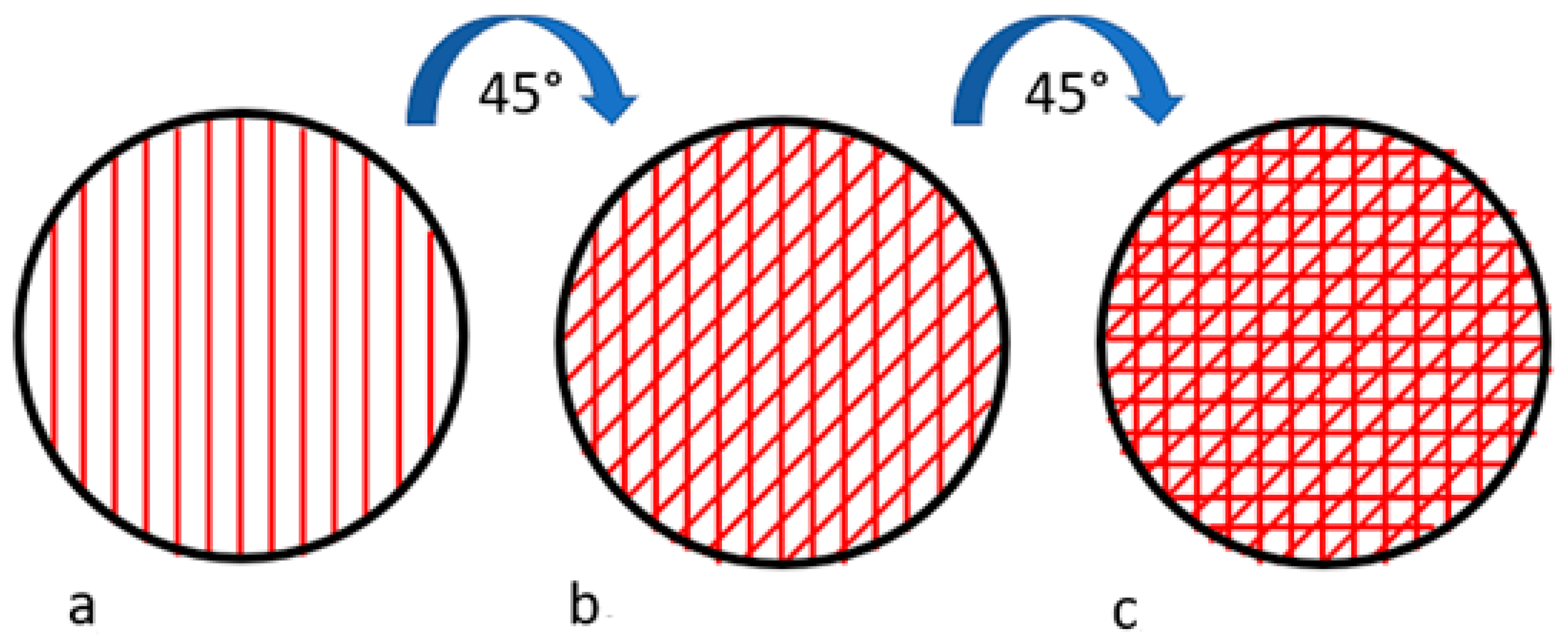
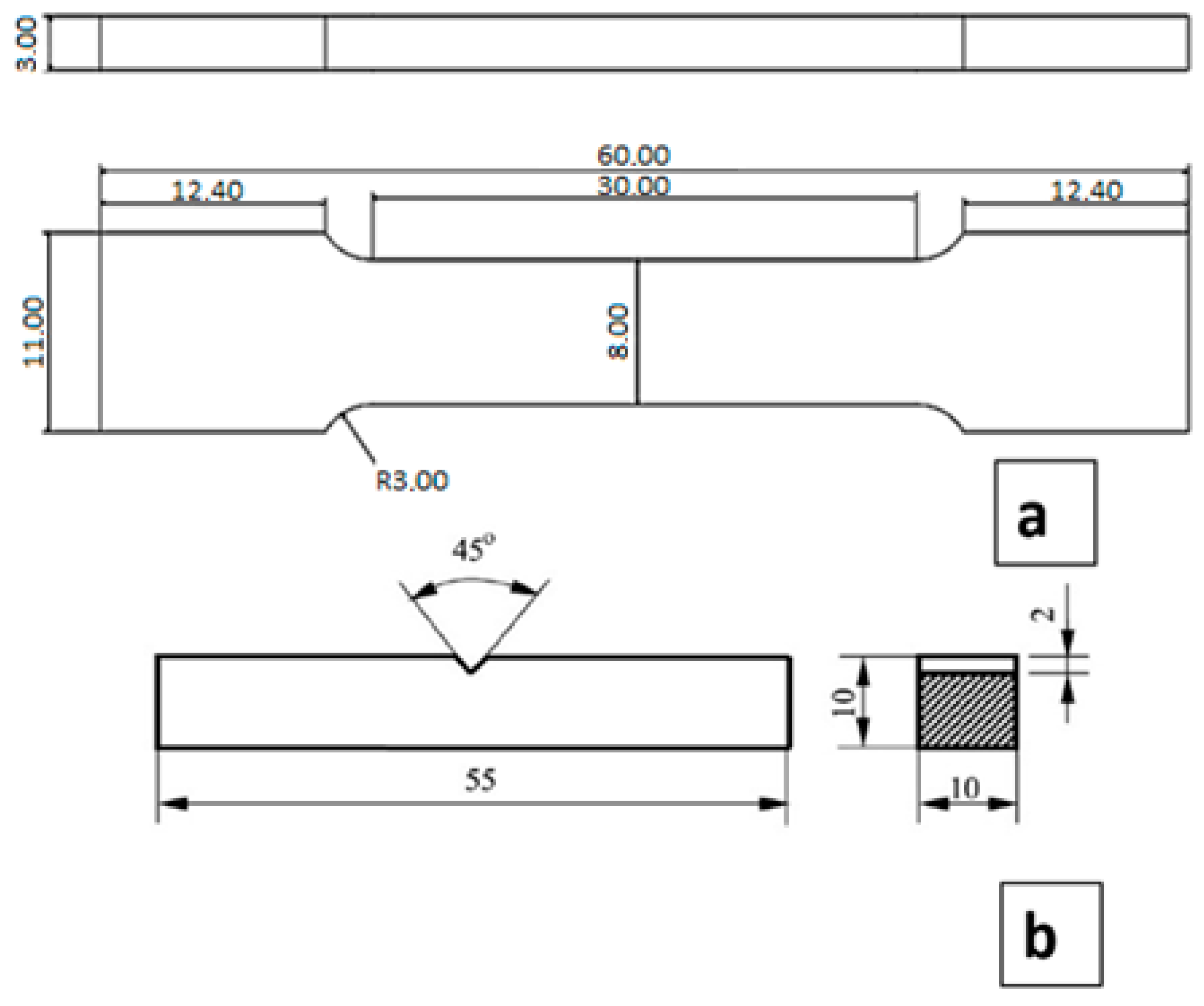
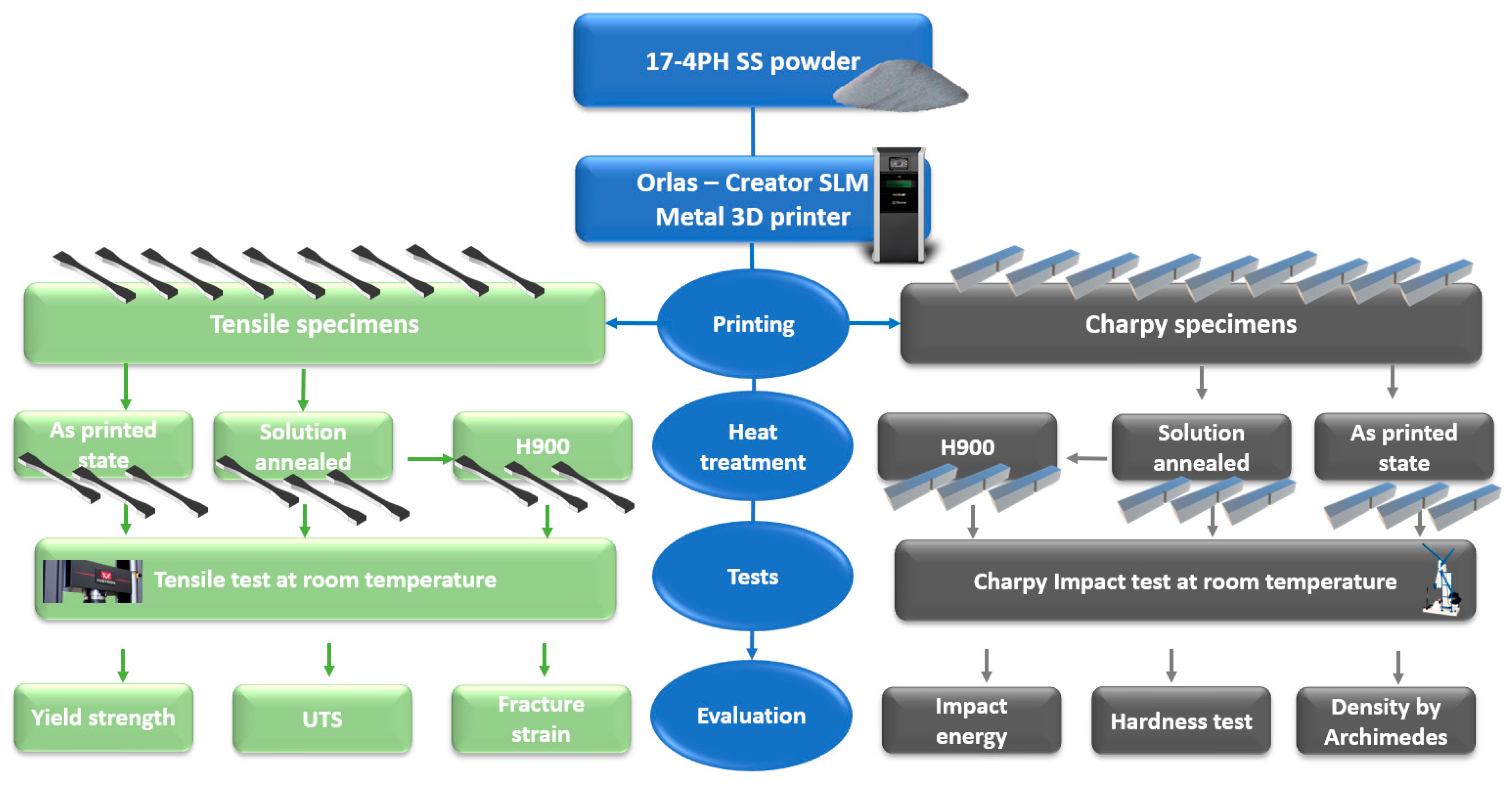
2. Materials and Methods

The selection of process parameters in our study was a result of a comprehensive approach. Initially, we extensively reviewed the existing literature in the field to identify commonly used and well-established process parameters employed in similar studies. These parameters served as a foundation for our research. Furthermore, we conducted preliminary experiments to evaluate the performance and feasibility of different process parameters. Via these experiments, we assessed their impact on the desired outcomes and determined the most appropriate range for our specific experimental setup. Practical constraints, such as equipment limitations, were also taken into account during the finalization of parameter selection. While we recognize that there are numerous process parameters that could potentially influence the outcomes, we carefully chose a subset that we believed would yield meaningful insights within the scope of our research objective.
The base material used for this research work was water-atomized 17-4PH stainless steel powder supplied by Oerlikon. The average particle size was 40 µm, which is widely used in AM and approved by both the German Federal Office of Civil Aeronautics and the German Federal Office of Defence Technology and Procurement. The morphology of the powder is mainly spherical, which is favorable for most additive manufacturing processes due to its excellent flowability and its high apparent density. However, as shown in Figure 1, the powder contained some particles with an irregular shape, which reduced the flowability and the apparent density of the powder bed. Furthermore, this can negatively affect the compactness of the 3D-printed parts. Yet, these particles are similar in shapes and sizes to those observed in the work of P. Ponnusamy et al. [16], in which the same alloy was considered. The official certificate (specified in the datasheet of the powder alloy) and the measured (ICP or inductively coupled plasma method) chemical composition of the initial powder are shown in Table 2.
The LPBF machine used in this experiment was an Orlas–Creator SLM machine, using an Yb fiber, a 1070 nm wavelength laser as an energy source, nitrogen shield gas and a ~40 µm average accuracy. The printing strategy is a scan of parallel lines with a 45° clockwise rotation for each deposited layer, thus creating a crosshatch pattern, as depicted in Figure 2. This strategy is typically used in 3D printing [16,17] to improve the strength and quality of printed parts.
The selected pattern improves the adhesion between the layers and prevents delamination. Delamination is a serious production flaw that occurs when there is improper bonding between successive layers, leading to permanent deformation due to residual stresses. In order to execute this approach, it is necessary to adjust the settings of the 3D printer software to position the heat source at a 45-degree angle relative to the previous scanning direction. This configuration involves a complete 360-degree rotation every eight consecutive layers. This method enables the machine to maintain control over the desired structural integrity, resulting in improved mechanical properties and a more seamless layer construction. Additionally, the powder feed was supplied using a rubber coater, which moved in counterclockwise circular motions. Tensile specimens in the shape of rectangular dog bones and Charpy specimens were printed, adhering to the dimensions depicted in Figure 3. In the case of the Charpy specimens, the V notch was machined after the printing.
All printed samples were made on a horizontal (0°) orientation as it has been proven to be the favorable orientation for this type of testing [18]. Six as-printed tensile specimens and Charpy specimens were solution-heat-treated (annealed) at 1038 °C for 30 min in argon atmosphere and then quenched with water. Three of the annealed specimens were subsequently aged at 480 °C for 60 min in argon atmosphere. The heating rate was 10 °C/min in both heat treatment processes. The density of the samples was determined by the Archimedes method. The hardness of the samples was measured using the Vickers method (HV10) [19] on a Wolpert UH930. Instron 5982 equipment was utilized for the tensile tests at room temperature. Tensile tests were conducted according to ASTM E8/E8M standard [20]. Charpy tests were conducted according to ASTM E23-16b [21], using a Schenck-Trebel of 300 J capacity. Three tests were carried out on each condition. The strain rate was 3 mm/min. The microstructure and the broken surface of the tested samples were investigated using optical microscopy (OM) and scanning electron microscopy (SEM) with C. Zeiss Axio Image and a C. Zeiss EVO MA 10 equipment, respectively. The experimental flowchart of the additively manufactured 17–4PH stainless steel is shown in Figure 4.

3. Results

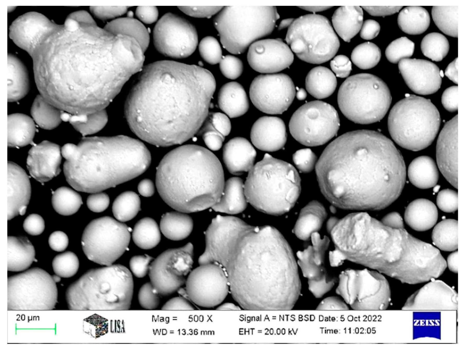
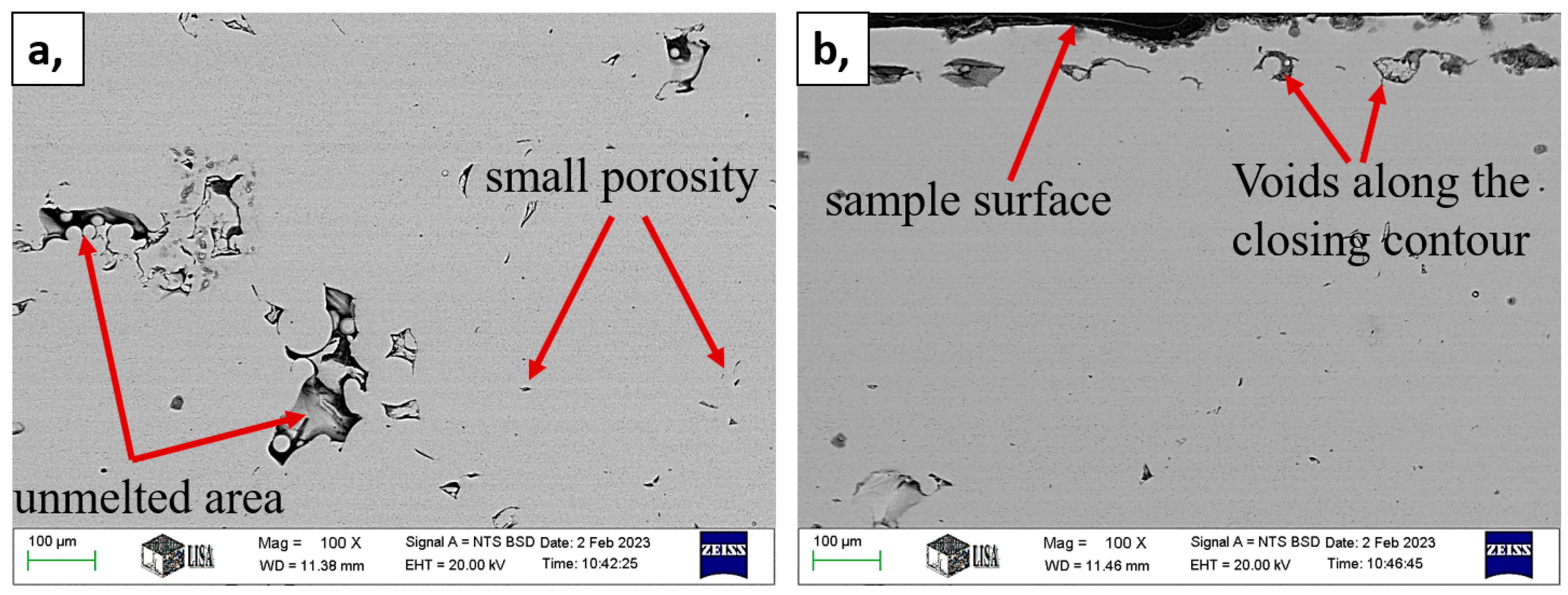
3.1. Density and Microstructure

The bulk density of the porosity-free, CP-wrought 17-4PH stainless steel was measured to be 7.75 g/cm3 [22]. The density of the AM products shows generally a lower value compared to the CP metals. In conventional processes (CP), a substantial amount of plastic deformation is applied, which helps eliminate the porosity present in the initial cast ingot. In contrast, in the field of additive manufacturing (AM), the use of long pressureless sintering or hot isostatic pressing (HIP) can reduce porosity, but it is inevitable to have some remaining porosities in the structure. This can significantly reduce the deformability as well as the strength and toughness of the material. The overall density results of the produced samples can be seen in Table 3, where the measured density and the calculated relative density values were also determined. The results show that the porosity lies between 1.5 and 2.7%. This is close to the literature’s data for sintering processes [23,24,25]. The applied heat treatments did not have any further effects on the density.
As depicted in Figure 5, the micrograph reveals the presence of two types of porosity within the microstructure. The majority of these voids exist on a microscale, with diameters less than 1–2 µm. However, there are a few voids that possess larger sizes but are less abundant. This type of porosity arises from inadequate melting during the 3D printing process, which will be further discussed in the analysis of fractured surfaces. Typically, the larger voids are observed along the outer rim of the specimen (Figure 5b). This phenomenon is well known in the realm of LPBF techniques as the process involves precise edge definition. With each layer, a closing contour is added, typically one (originally three). Although this contour addition is a machine-specific parameter and unavoidable, it does not significantly impact the mechanical properties.

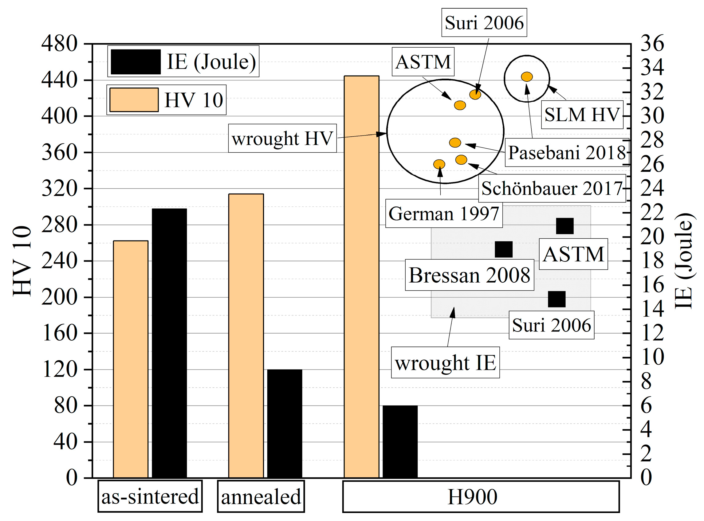
3.2. Hardness and Toughness

The hardness and toughness values of the tested Charpy samples under different heat-treated conditions are presented in Figure 6. The results indicate that the as-printed state exhibits the lowest hardness and the highest toughness. The average hardness of the as-printed samples is insufficient for most engineering applications. However, the advantage of this alloy lies in its ability to be hardened by heat treatment. Prior to the aging heat treatment, annealing is performed. This heat treatment aims to maintain all the alloying elements in a solid solution state achieved by rapid cooling from the austenitic phase. Typically, this is the softest state of the material. However, as demonstrated by the results, the hardness of the annealed samples is higher than that of the as-printed state. According to the ASTM A693 standard, the maximum hardness is obtained in the annealed state, with a Rockwell hardness of 38 (HRC) or a corresponding Vickers hardness of 348 (HV). Our measured value of 314 (HV10) slightly falls below this maximum value. In practical terms, the hardest state of this alloy can be achieved by the H900 aging treatment. In this state, the hardness values usually range between 388 HV and 458 HV [26,27,28]. In our case, the average hardness of the aged samples is close to the maximum value of 445 (HV10). Regarding the measured impact energy (IE) values, an opposite trend can be observed.
This observed trend can be attributed to the fact that harder samples have a higher susceptibility to fracture when subjected to high-impact forces, resulting in lower impact energy (IE) values. The as-printed state exhibits the highest IE value of 22 Joules. However, after the annealing process, this value decreases to 9 joules. The lowest IE value of 6 joules was measured in the H900 state. In comparison to the results reported in the literature and the standard for the CP 17-4PH alloy, this impact energy is relatively low. The presence of unmelted areas within the printed microstructure (Figure 7) is undoubtedly the reason behind this discrepancy. These areas significantly reduce the toughness of the material [31].

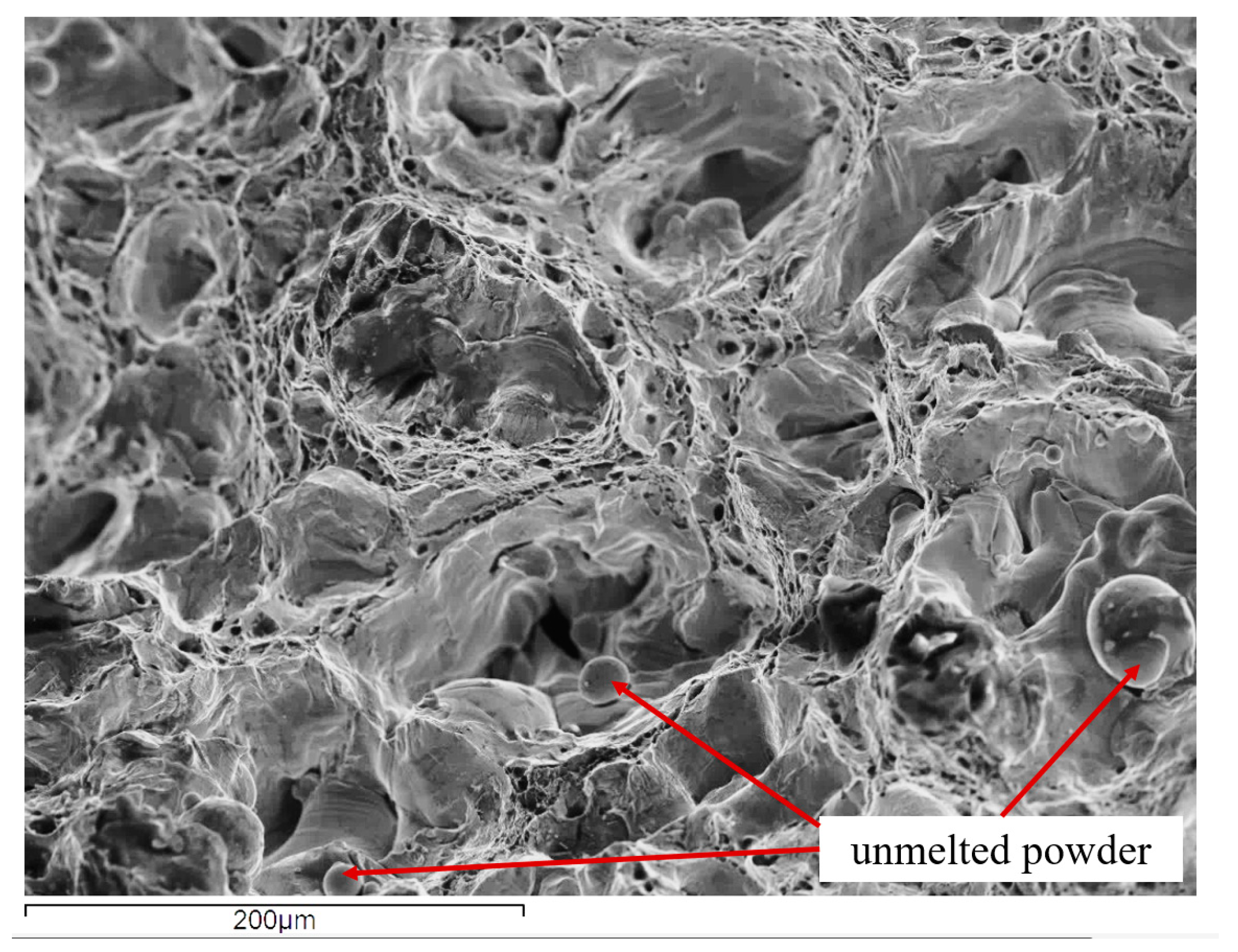
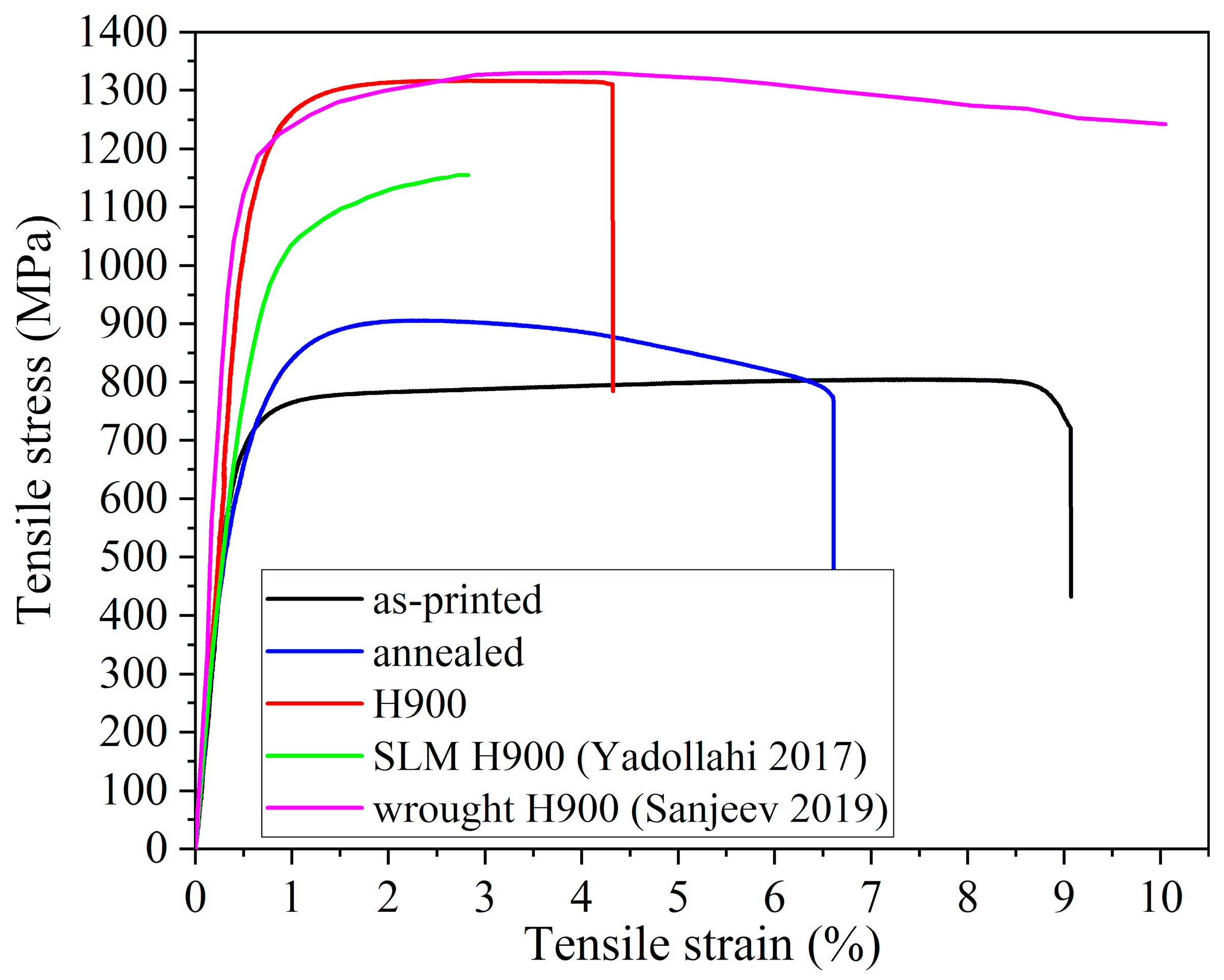
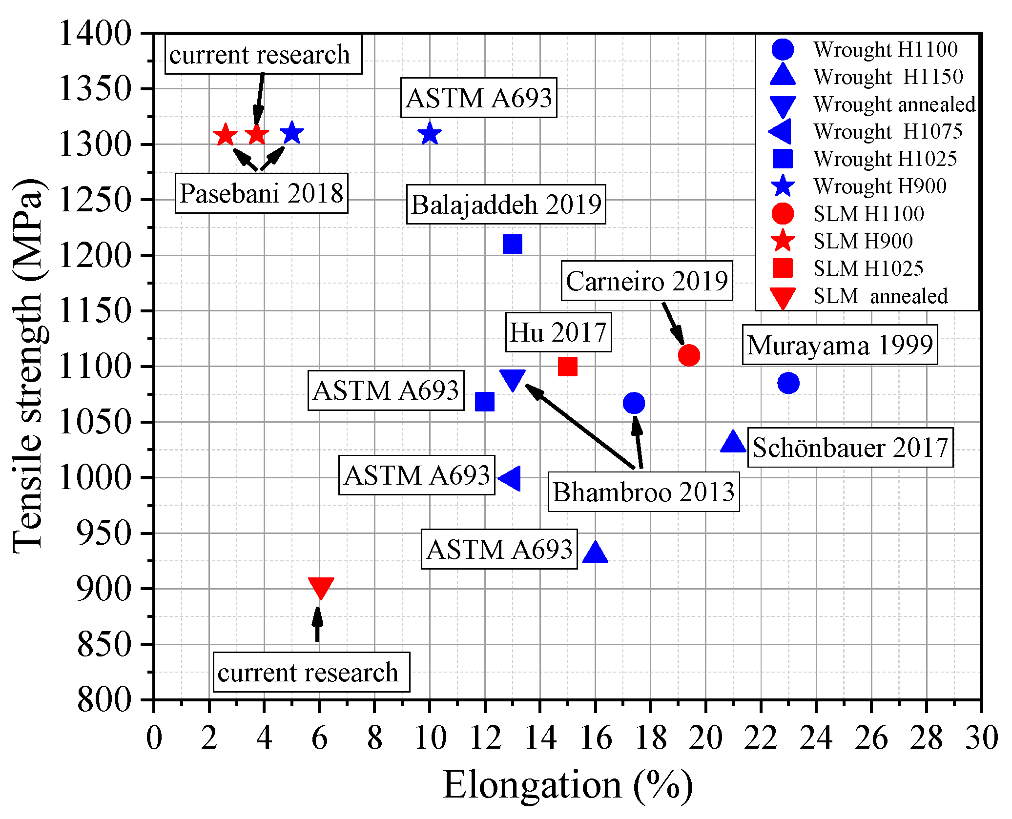
3.3. Tensile Properties

The typical tensile curves for the three different heat-treated conditions of the investigated material are depicted in Figure 8 and Table 4. It was determined that the heat treatment had a notable impact on the plastic deformation behavior of the material, as evidenced by the shape of the curves. In the case of the as-printed sample, a slight strain hardening effect can be observed between the yield strength (YS) and ultimate tensile strength (UTS). This curve exhibits the highest level of uniform plastic deformation and the lowest stress values. Following the UTS, a short period of non-uniform plastic deformation, known as necking, can be observed. Conversely, the annealed sample displays a different pattern. While the strain hardening period is short, the necking period is longer. The curve for the H900 sample exhibits a distinct curvature. After yielding, the tensile stress shows a sustained elongation phase. No further necking is observed after the UTS, and the sample fractures rapidly. The trend observed in the hardness and toughness values is also reflected in the tensile properties. The strength of the samples increases as a result of the heat treatment, while the plastic deformability experiences a significant decrease.
The values for yield strength (YS), ultimate tensile strength (UTS) and strain at break obtained from the tensile curves, along with the H900 value, are presented in Figure 9. The figure also includes data from the literature on CP- and AM-produced samples in different aged states. By comparing the results of the CP and AM alloy, as depicted in the diagram, it can be observed that the highest UTS can be achieved by the H900 treatment (1309 MPa), which is nearly equivalent to that of traditional manufacturing methods (1310 MPa). Generally, AM processes are often promoted as post-production free processes, but the as-built condition lacks the necessary mechanical properties for practical use. A comparison was made with similar results reported in the literature. In their respective studies, H.R. Lashgari et al. [33] and F.R. Andreacola et al. [14] applied heat treatment to their specimens, resulting in UTS values close to 1300 MPa, while the as-printed mechanical strength was approximately 900 MPa.
Figure 10 provides optical microscopy (OM) and scanning electron microscopy (SEM) micrographs of the fracture surfaces of the tensile specimens. Upon comparing the fracture surfaces, it becomes evident that the fracture mechanism differs. It is apparent that all the fractured surfaces exhibit a notable presence of porosity accompanied by unmelted powder. This is clearly visible in Figure 10d, although a similar amount can be observed on all other investigated surfaces. As indicated by the tensile curves, the curves corresponding to the as-printed and H900 aged samples display a short period of necking in comparison to the curve of the annealed sample. A short necking period implies that the fracture occurs without significant plastic deformation. This can be observed in Figure 10a,c,d,f, where cleavage fracture surfaces are depicted. Conversely, the tensile curve of the annealed sample exhibits a prolonged necking period. This substantial amount of plastic deformation is visible on the ductile-type fractured surfaces shown in Figure 10b,e.

4. Conclusions

The present work focused on the production of LPBF samples with a desired orientation towards enhancing their properties in a specific direction. 17-4PH SS powder has been used for the production of the samples, being a widely used material for aeronautical applications, such as landing gear components wing spars and engine mounts, as well as for producing control rods, exhaust components, cockpit fasteners or even simple brackets. Such parts are predominantly loaded in one direction. By optimizing the properties of an additively manufactured 17-4PH alloy, it may be possible to produce parts with lighter and more efficient designs that can replace conventional parts made using traditional manufacturing methods. The properties of the produced specimens have been compared with those of corresponding parts from the literature made via traditional manufacturing methods and other AM processes. While the aviation industry places high standards on conventional crafting methods, their potential for increased complexity is limited. However, powder-based methods offer a significant improvement in this regard. Based on the results of the tensile tests, notable differences in characteristics are observed between parts made conventionally and those produced using our AM process. CP parts, in their as-made condition, exhibit superior tensile strength properties but lack elongation. On the other hand, LPBF-produced parts, when subjected to treatment, demonstrate competitive properties in this aspect. Moreover, the narrow standard deviation of the LPBF values indicates the stability of this manufacturing method. Our findings also suggest that additional treatments can enhance the potential applicability of these powder-based parts, particularly in terms of ultimate tensile strength (UTS) and yield strength (YS). This aligns with the requirement stated in MIL-STD-1530D, which specifies no yielding at the 100% design limit load [6] while still allowing for optimal design freedom to achieve greater complexity. Despite the printing jobs not being 100% accurate in terms of surface finish and the occasional presence of unmelted particles resulting in 2-3% porosity, the results are remarkable compared to other AM technologies, as supported by values reported in the literature. These unmelted zones were subsequently minimized by annealing and aging heat treatments. In conclusion, additively manufactured 17-4 PH parts have the potential to find application in the aviation sector, although further investigations are necessary to assess their actual applicability. Future research endeavors may focus on improving the stability of 3D printing jobs or exploring alternative heat treatment methods, considering their potential impact on the mechanical properties of AM parts. Additive manufacturing (AM) has the potential to revolutionize the way parts are designed and produced, particularly in industries like aerospace in which weight reduction is a critical factor in improving performance and fuel efficiency, which is also emphasized in US Army Directive 2019-29 [39]. By using AM to produce parts with reimagined, lighter geometries, it may be possible to reduce the overall weight of aircraft and spacecraft, resulting in significant improvements in fuel efficiency and cost savings. Moreover, the utilization of AM for part production brings additional advantages, including decreased material waste, enhanced design flexibility and expedited production times. These benefits make AM a promising alternative to conventional manufacturing methods in various industries, including aerospace. Nevertheless, it is important to acknowledge that the adoption of AM in the aerospace sector presents certain challenges that must be overcome. Quality control, certification processes and material limitations are among the key issues that need to be addressed before AM can be widely embraced in the industry.

Author Contributions

Conceptualization, Z.G. and T.M.; methodology, S.E.K.; software, S.E.K. and T.M.; validation, S.E.K. and T.M.; formal analysis, S.E.K., T.M., D.M. and E.T.; investigation, S.E.K. and T.M.; resources, S.E.K., T.M. and Z.G.; data curation, S.E.K., T.M., D.M. and E.T.; writing—original draft preparation, S.E.K.; writing—review and editing, T.M., D.M., E.T. and D.P.; visualization, S.E.K. and T.M.; supervision, Z.G. and L.V.; project administration, G.G.; funding acquisition, Z.G. All authors have read and agreed to the published version of the manuscript.

Funding

The work was carried out as part of the UMA3 project funded by the European Union’s Horizon 2020 research and innovation program under grant agreement No 952463.

Data Availability Statement

The data presented in this study are available in the following paper: “Additive Manufacturing of 17-4PH Alloy: Tailoring Printing Orientation for Enhanced Aerospace Application Performance”.

Acknowledgments

The experiments were carried out at the University of Miskolc, Faculty of Materials and Chemical Engineering, Institute of Physical Metallurgy, Metalforming and Nanotechnology and Institute of Foundry Engineering.

Conflicts of Interest

The authors declare no conflict of interest.

References

  1. Nickels, L. AM and aerospace: An ideal combination. Met. Powder Rep. 2015, 70, 300–303. [Google Scholar] [CrossRef]
  2. Berrocal, L.; Fernández, R.; González, S. Topology optimization and additive manufacturing for aerospace components. Prog. Addit. Manuf. 2019, 4, 83–95. [Google Scholar] [CrossRef]
  3. Gibson, I.; Rosen, D.W.; Stucker, B. Additive Manufacturing Technologies: 3D Printing. In Rapid Prototyping, and Direct Digital Manufacturing, 2nd ed.; Springer: Berlin/Heidelberg, Germany, 2015. [Google Scholar]
  4. Liu, R.; Wang, Z.; Sparks, T.; Liou, F.; Newkirk, J. Aerospace applications of laser additive manufacturing. In Laser Additive Manufacturing; Woodhead Publishing: Cambridge, UK, 2017; pp. 351–371. [Google Scholar] [CrossRef]
  5. USAF Structures Bulletin EZ-SB-19-01, Durability and Damage Tolerance Certification for Additive Manufacturing of Aircraft Structural Metallic Parts, Wright Patterson Air Force Base, OH, USA, 10 June 2019. Available online: https://daytonaero.com/wp-content/uploads/EZ-SB-19-01.pdf (accessed on 27 February 2023).
  6. MIL-STD-1530D; Department of Defense Standard Practice Aircraft Structural Integrity Program (ASIP). Military and Government Specs & Standards (Naval Publications and Form Center) (NPFC): New York, NY, USA, 2016.
  7. Kundu, S.; Jones, R.; Peng, D.; Matthews, N.; Alankar, A.; Raman, S.R.K.; Huang, P. Review of Requirements for the Durability and Damage Tolerance Certification of Additively Manufactured Aircraft Structural Parts and AM Repairs. Materials 2020, 13, 1341. [Google Scholar] [CrossRef] [PubMed] [Green Version]
  8. Zerbst, U.; Bruno, G.; Buffiere, J.Y.; Wegener, T.; Niendorf, T.; Wu, T.; Zhang, X.; Kashaev, N.; Meneghetti, G.; Hrabe, N.; et al. Damage tolerant design of additively manufactured metallic components subjected to cyclic loading: State of the art and challenges. Prog. Mater. Sci. 2021, 121, 100786. [Google Scholar] [CrossRef]
  9. Khorasani, M.; Ghasemi, A.; Leary, M.; Downing, D.; Gibson, I.; Sharabian, E.G.; Veetil, J.K.; Brandt, M.; Bateman, S.; Rolfe, B. Benchmark models for conduction and keyhole modes in laser-based powder bed fusion of Inconel 718. Opt. Laser Technol. 2023, 164, 109509. [Google Scholar] [CrossRef]
  10. Lavecchia, F.; Pellegrini, A.; Galantucci, L.M. Comparative study on the properties of 17-4 PH stainless steel parts made by metal fused filament fabrication process and atomic diffusion additive manufacturing. Rapid Prototyp. J. 2023, 29, 393–407. [Google Scholar] [CrossRef]
  11. Giganto, S.; Martínez-Pellitero, S.; Barreiro, J.; Leo, P.; Ángeles Castro-Sastre, M. Impact of the laser scanning strategy on the quality of 17-4PH stainless steel parts manufactured by selective laser melting. J. Mater. Res. Technol. 2022, 20, 2734–2747. [Google Scholar] [CrossRef]
  12. Ponnusamy, P.; Sharma, B.; Masood, S.H.; Rahman Rashid, R.A.; Rashid, R.; Palanisamy, S.; Ruan, D. A study of tensile behavior of SLM processed 17-4 PH stainless steel. Mater. Today Proc. 2021, 45, 4531–4534. [Google Scholar] [CrossRef]
  13. Liverani, E.; Lutey, A.; Ascari, A.; Fortunato, A. The effects of hot isostatic pressing (HIP) and solubilization heat treatment on the density, mechanical properties, and microstructure of austenitic stainless steel parts produced by selective laser melting (SLM). Int. J. Adv. Manuf. Technol. 2020, 107, 109–122. [Google Scholar] [CrossRef]
  14. Andreacola, F.R.; Capasso, I.; Pilotti, L.; Brando, G. Influence of 3D-printing parameters on the mechanical properties of 17-4PH stainless steel produced through Selective Laser Melting. Frat. Ed Integrità Strutt. 2021, 58, 282–295. [Google Scholar] [CrossRef]
  15. Raj, S.; Ghosn, L.; Lerch, B.; Hebsur, M.; Cosgriff, L.; Fedor, J. Mechanical properties of 17-4PH stainless steel foam panels. Mater. Sci. Eng. A 2007, 456, 305–316. [Google Scholar] [CrossRef] [Green Version]
  16. Ponnusamy, P.; Masood, S.H.; Palanisamy, S.; Rahman Rashid, R.A.; Ruan, D. Characterization of 17-4PH alloy processed by selective laser melting. Mater. Today Proc. 2017, 4, 8498–8506. [Google Scholar] [CrossRef]
  17. Liu, C.Y.; Tong, J.D.; Jiang, M.G.; Chen, Z.W.; Xu, G.; Liao, H.B.; Wang, P.; Wang, X.Y.; Xu, M.; Lao, C.S. Effect of scanning strategy on microstructure and mechanical properties of selective laser melted reduced activation ferritic/martensitic steel. Mater. Sci. Eng. A 2019, 766, 138364. [Google Scholar] [CrossRef]
  18. Aripin, M.A.; Sajuri, Z.; Jamadon, N.H.; Baghdadi, A.H.; Syarif, J.; Mohamed, I.F.; Aziz, A.M. Effects of Build Orientations on Microstructure Evolution, Porosity Formation, and Mechanical Performance of Selective Laser Melted 17-4 PH Stainless Steel. Metals 2022, 12, 1968. [Google Scholar] [CrossRef]
  19. ASTM E 92; Standard Test Method for Vickers Hardness of Metallic Materials. ASTM International: West Conshohocken, PA, USA, 2017.
  20. ASTM E8/E8M-22; Standard Test Methods for Tension Testing of Metallic Materials. ASTM International: West Conshohocken, PA, USA, 2022.
  21. ASTM E23-16b; Standard Test Methods for Notched Bar Impact Testing of Metallic Materials. ASTM International: West Conshohocken, PA, USA, 2018.
  22. ASTM A693-16(2022); Standard Specification for Precipitation-Hardening Stainless and Heat-Resisting Steel Plate, Sheet, and Strip. ASTM International: West Conshohocken, PA, USA, 2022.
  23. Simchi, A.; Rota, A.; Imgrund, P. An investigation on the sintering behavious of 316L and 17-4ph stainless steel powders for graded composites. Mater. Sci. Eng. A 2006, 424, 282–289. [Google Scholar] [CrossRef]
  24. Szewczyk-Nykiel, A.; Gadek, S.; Hebda, M.; Nykiel, M.; Pieczonka, T.; Kazior, J. Influence of Sintering Atmosphere on Densification Development of 17-4PH stainless steel powder. Materials 2023, 16, 760. [Google Scholar] [CrossRef]
  25. Wu, Y.; Blaine, D.; Marx, B.; Schlaefer, C.; German, R.M. Sintering Densification and Microstructural Evolution of Injection Molting Grade 17-4 PH Stainless steel Powder. Metall. Mater. Trans. A 2002, 33, 2185–2194. [Google Scholar] [CrossRef]
  26. Suri, P.; Smarslok, B.P.; German, R.M. Impact properties of sintered and wrought 17-4 PH stainless steel. Powder Metall. 2006, 49, 40–47. [Google Scholar] [CrossRef]
  27. Pasebani, S.; Ghayoor, M.; Badwe, S.; Irrinki, H.; Atre, S.V. Effects of atomizing media and post processing on mechanical properties of 17-4 PH stainless steel manufactured via selective laser melting. Addit. Manuf. 2018, 22, 127–137. [Google Scholar] [CrossRef]
  28. German, R.M. Thermal Processing Optimization of Injection Molded Stainless Steel Powders. Mater. Manuf. Process. 1997, 12, 713–735. [Google Scholar] [CrossRef]
  29. Schönbauer, B.M.; Yanase, K.; Endo, M. The influence of various types of small defects on the fatigue limit of precipitation-hardened 17-4PH stainless steel. Theor. Appl. Fract. Mech. 2017, 87, 35–49. [Google Scholar] [CrossRef]
  30. Bressan, J.D.; Daros, D.P.; Sokolwski, A.; Mesquita, R.A.; Barbosa, C.A. Influence of hardness on the wear resistance of 17-4 PHstainless steel evaluated by the pin-on-disc testing. J. Mater. Process. Technol. 2008, 205, 353–359. [Google Scholar] [CrossRef]
  31. Sanjeev, K.C.; Nezhadfar, P.D.; Phillips, C.; Kennedy, M.S.; Shamsei, N.; Jackson, R.L. Tribological behavior of 17–4 PH stainless steel fabricated by traditional manufacturing and laser-based additive manufacturing methods. Wear 2019, 440–441, 203100. [Google Scholar]
  32. Yadollahi, A.; Shamsaei, N.; Thompson, S.M.; Elwany, A.; Bian, L. Effects of building orientation and heat treatment on fatigue behavior of selective laser melted 17-4 PH stainless steel. Int. J. Fatigue 2017, 94, 218–235. [Google Scholar] [CrossRef]
  33. Lashgari, H.R.; Adabifiroozjaei, E.; Kong, C.; Molina-Luna, L.; Li, S. Heat treatment response of additively manufactured 17-4PH stainless steel. Mater. Charact. 2023, 197, 112661. [Google Scholar] [CrossRef]
  34. Murayama, M.; Hono, K.; Katayama, Y. Microstructural evolution in a 17-4 PH stainless steel after aging at 400 °C. Metall. Mater. Trans. A 1999, 30, 345–353. [Google Scholar] [CrossRef]
  35. Carneiro, L.; Jalalahmadi, B.; Ashtekar, A.; Jiang, Y. Cyclic deformation and fatigue behavior of additively manufactured 17-4 PH stainless steel. Int. J. Fatigue 2019, 123, 22–30. [Google Scholar] [CrossRef]
  36. Bhambroo, R.; Roychowdhury, S.; Kain, V.; Raja, V.S. Effect of reverted austenite on mechanical properties of precipitation hardenable 17-4 stainless steel. Mater. Sci. Eng. A 2013, 568, 127–133. [Google Scholar] [CrossRef]
  37. Balajaddeh, B.M.; Naffakh-Moosavy, H. Pulsed Nd:YAG laser welding of 17-4 PH stainless steel: Microstructure, mechanical properties, and weldability investigation. Opt. Laser Technol. 2019, 119, 105651. [Google Scholar] [CrossRef]
  38. Hu, Z.; Zhu, H.; Zhang, H.; Zeng, X. Experimental investigation on selective laser melting of 17-4PH stainless steel. Opt. Laser Technol. 2017, 87, 17–25. [Google Scholar] [CrossRef]
  39. US Army Directive 2019-29, Enabling Readiness and Modernization Through Advanced Manufacturing, Secretary of The Army, Pentagon, Washington DC, 18 September 2019. Available online: https://armypubs.army.mil/epubs/DR_pubs/DR_a/pdf/web/ARN19451_AD2019-29_Web_Final.pdf (accessed on 27 February 2023).
Figure 1. Morphology of 17-4 PH SS powder at 500×magnification.
Aerospace 10 00619 g001
Figure 2. Crosshatch pattern achieved by 45-degree-clockwise rotation: (a) first deposited layer; (b) second deposited layer; (c) third deposited layer.
Aerospace 10 00619 g002
Figure 3. Dimensions and shapes of the printed (a) and tensile (b) Charpy specimen.
Aerospace 10 00619 g003
Figure 4. Experimental procedure conducted on the (AM)17-4PH stainless steel tensile test specimens and Charpy specimens. The arrows represent the life cycle of each test piece.
Aerospace 10 00619 g004
Figure 5. Typical porosity morphology of the LPBF 3D-printed samples: (a) inside the sample; (b) close to the sample surface.
Aerospace 10 00619 g005
Figure 6. Hardness and impact energy at different heat-treated states [26,27,28,29,30]. Values from the same fields were marked with rectangle and circles.
Aerospace 10 00619 g006
Figure 7. SEM picture on a broken surface of a Charpy specimen.
Aerospace 10 00619 g007
Figure 8. Tensile curves of 17-4ph LPBF samples [31,32].
Aerospace 10 00619 g008
Figure 9. Tensile properties of the different values reported in the literature. CP parts are marked with blue, while AM parts are marked with red [27,29,34,35,36,37,38].
Aerospace 10 00619 g009
Figure 10. Fractured surfaces of (a,d) as-printed, (b,e) annealed and (c,f) H900 tensile specimens.
Aerospace 10 00619 g010
Table 1. Typical mechanical properties of commercially manufactured 17-4PH SS according to ASTM A564.
ConditionYS (MPa)UTS (MPa)Elongation (%)Hardness, VickersYS/UTSCharpy Impact Energy (Joule)
H90011711309104100.8922
H10259991068123490.9454
H1075861999133280.8661
H1150723930162920.7875
Table 2. Chemical composition of 17-4 PH stainless steel powder (wt. %).
CCrCuNiNbTaMnSiFe
Measured0.0117.13.034.460.27<0.01--Bal.
Certification0.0216.523.944.470.30-0.040.43Bal.
Table 3. Density of LPBF 17-4PH SS Charpy samples.
StateSample ρ Measured
(g/cm3)
ρ Relative (%)
as printed1.7.5497.30
2.7.6398.46
3.7.5296.98
annealed4.7.5897.76
5.7.5697.61
6.7.5697.58
H9007.7.5597.40
8.7.5497.27
9.7.5797.70
Table 4. Tensile properties of LPBF specimens in various conditions.
CONDITIONYS (MPA)UTS (MPA)EL (%)YS/UTS
AS PRINTED712 ± 6796 ± 89.4 ± 0.60.89
ANNEALED714 ± 5904 ± 66.1 ± 0.40.79
H900 (AGED)1190 ± 161309 ± 133.7 ± 0.70.91
Disclaimer/Publisher’s Note: The statements, opinions and data contained in all publications are solely those of the individual author(s) and contributor(s) and not of MDPI and/or the editor(s). MDPI and/or the editor(s) disclaim responsibility for any injury to people or property resulting from any ideas, methods, instructions or products referred to in the content.

