Mathematical Modelling of a Propellent Gauging System: A Case Study on PRISMA
Abstract
1. Introduction
- Mathematical modelling of propellent gauging systems
- Errors analysis of the propellant gauging systems
- Performing case study on PRISMA satellite.
2. PRISMA Mission and Mathematical Modelling
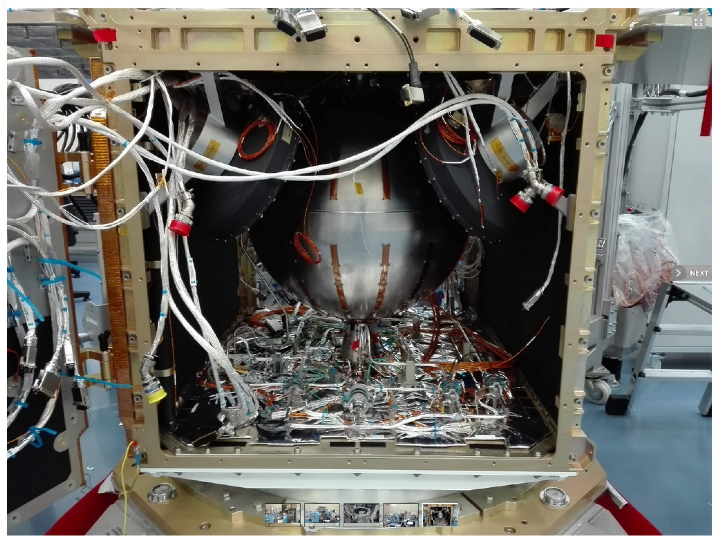
- Fuel tank: It is where the satellite stores its propellant.
- Pressure transducers: They measure the pressure of the propellant inside the tank.
- Temperature sensors: They measure the temperature of the propellant.
- Level sensors: They measure the level of the propellant inside the tank.
- Control electronics: They receive data from the pressure transducers, temperature sensors, and level sensors, and process this data to calculate the amount of propellant remaining in the tank.
- Communication interface: It enables the control electronics to transmit the calculated propellant level data to the satellite’s telemetry system.
2.1. Input Data from PRISMA
2.2. BKP Approach
Error Analysis for BKP Approach
2.3. Pressure−Volume−Temperature Approach
Error Analysis on PVT Approach
2.4. Thermal Propellant Gauging Approach
- Newton’s law of heating;
- By the thermal response of the system (in our case, systems can be considered as a combination of tank, propellant, and pressurant);
- Using mass fuel ratios;
Error Analysis of the TPG Approach
2.5. Algorithm Definition
- Once the status has been confirmed, it checks whether the two thrusters were working or only one was working during the firing.
- After this check, it reads the date and time of that operation to verify whether this analysis has already been carried out.
- According to the active number of thrusters, it calculates the total mass flow rate from the tank., i.e., in case two thrusters were working, the mass flow rate will be doubled.
- Then it considers the pressure and temperature values, which are in alignment with the above two conditions, and then calculates residual propellant mass and relative errors using the formulae.
- The two propellant masses and errors will be calculated applying two different approaches viz BKP and PVT method.
- Finally, it prints the results into two txt files; one is for the total history of firing with firing time and the other one will have a summary file, which also provides input for the next analysis.
- A graph will be plotted using the data from the summary file after every firing.
3. Software Implementation
3.1. Analysis of Propellant Gauging
3.1.1. Input Phase
3.1.2. Main Phase
3.1.3. Output Phase
3.2. Telemetry Data Analysis for Propellant Gauging
4. Results and Discussion
4.1. BKP Approach
4.2. PVT Approach
4.3. Thermal Propellant Gauging Approach
4.4. Comparative Study of Errors on Different Methods
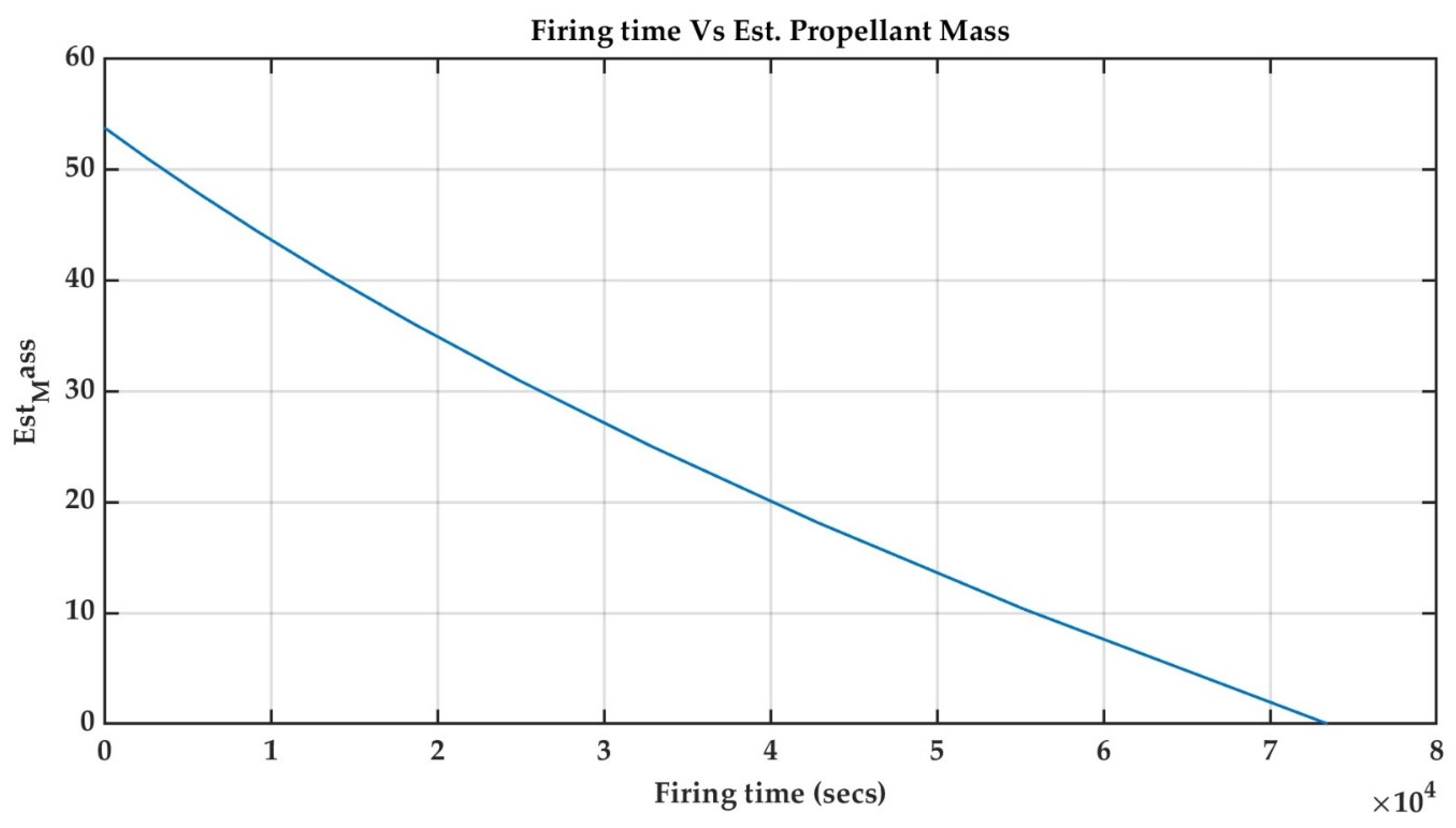
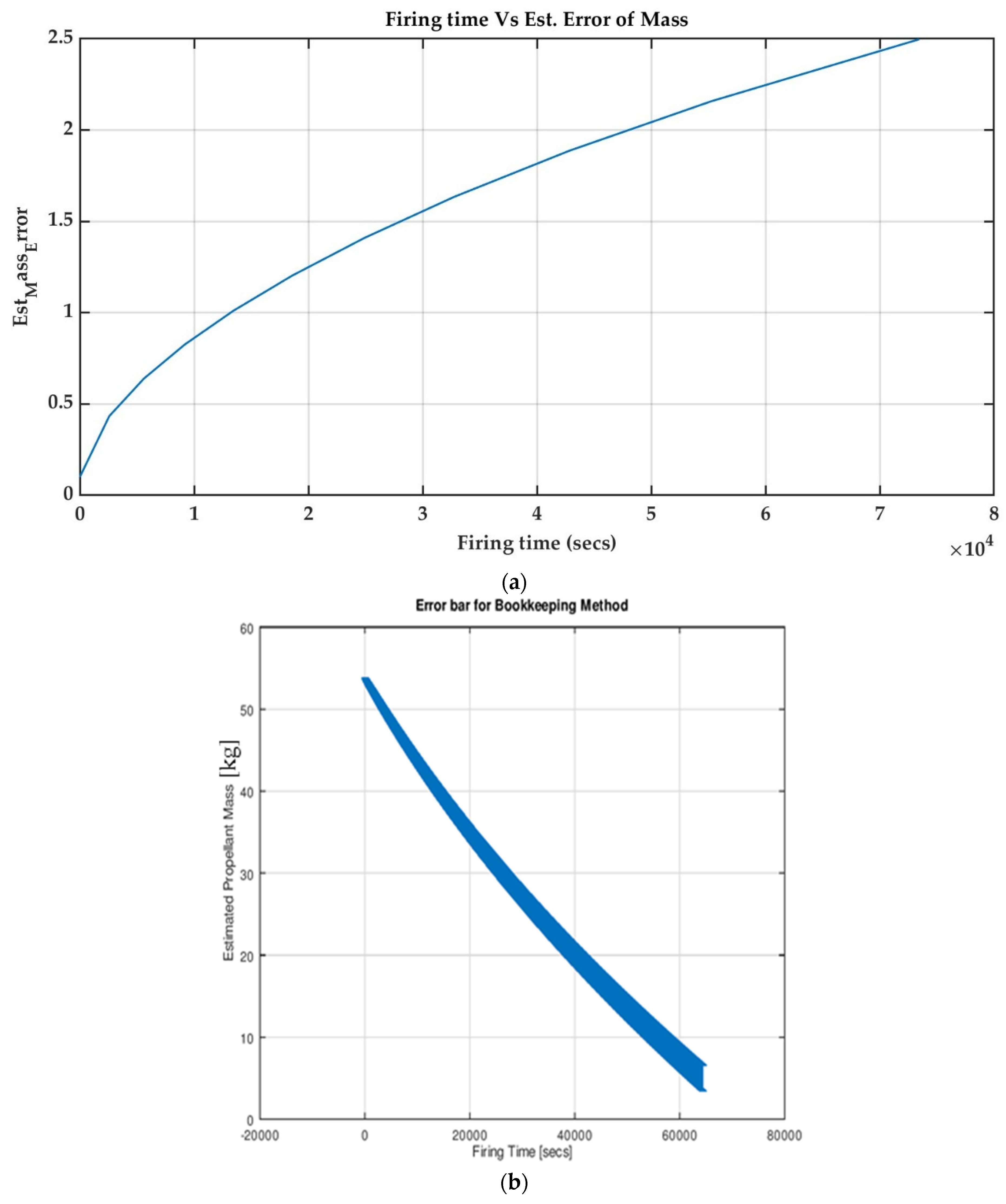
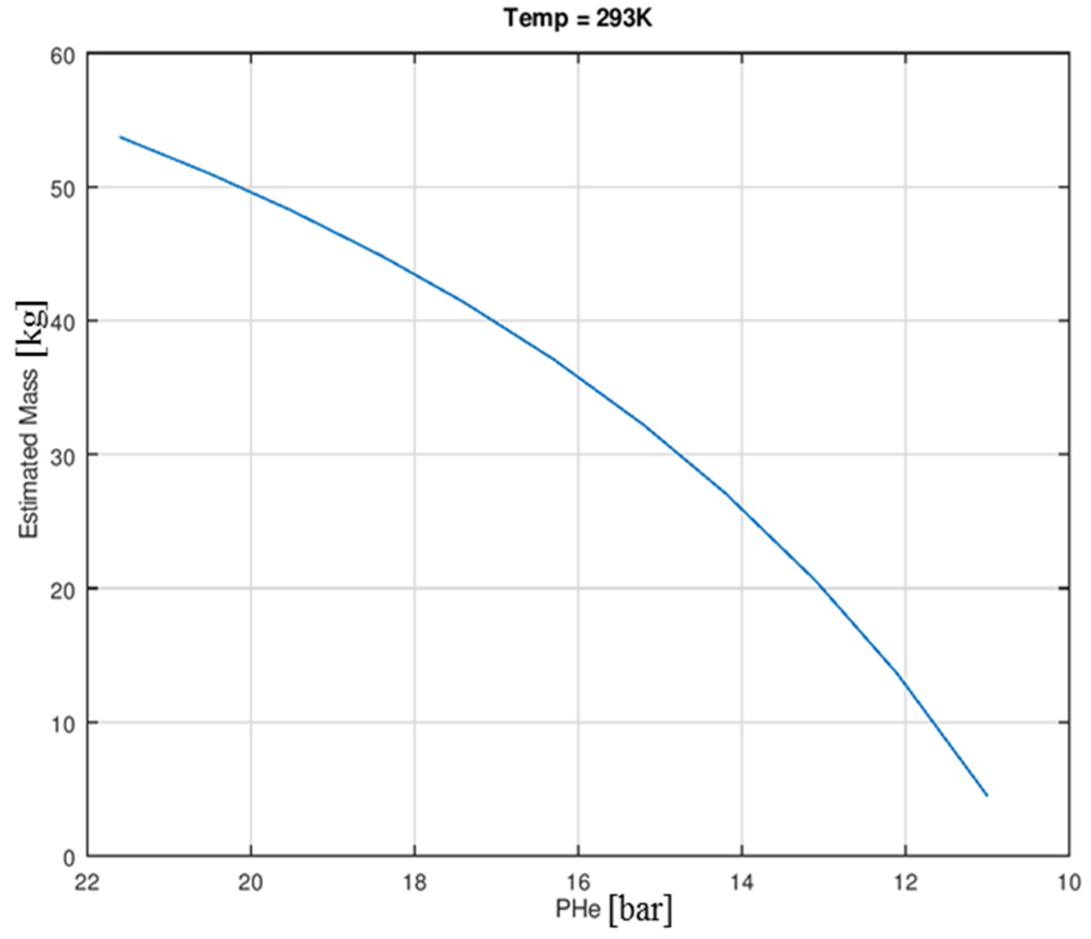
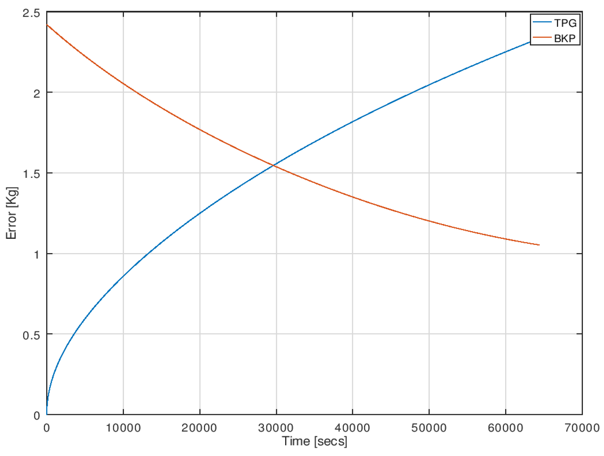
- Firstly, the BKP method is one of the best methods for gauging propellant from BoL up to a certain limit. After this, the error in the BKP values increases since it calculates by a cumulative method. In this case, the error was 0.1 kg (0.1%) in the beginning, and it increased to 2.5 kg (4.6%) till the end of life (EoL).
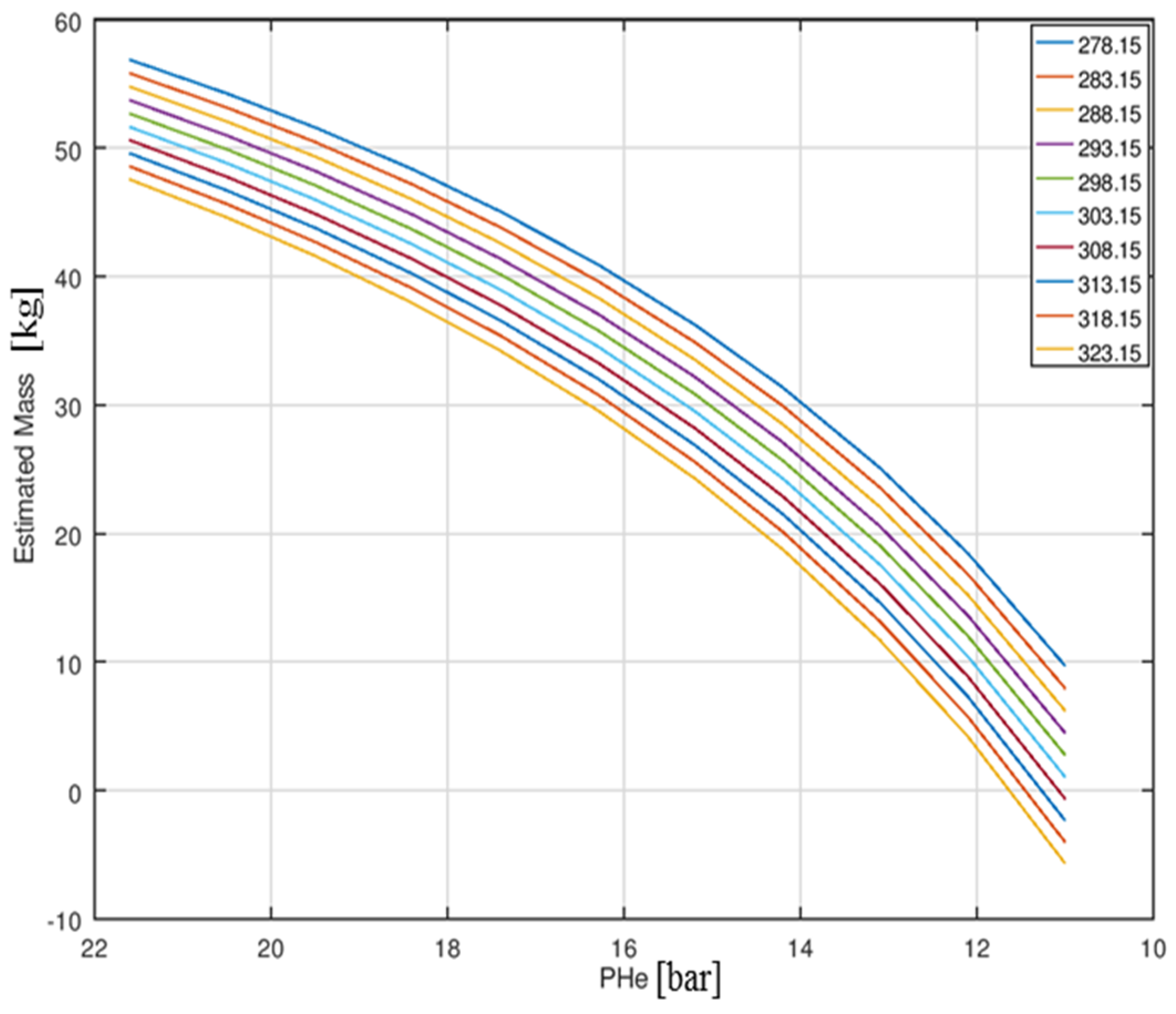
- Secondly, the PVT method has shown a moderate result (error) which is 0.69 kg (1%) and increased up to 2.6 kg (4.8%) till the EoL. Since it uses two parameters, i.e., pressure and temperature values for calculation, both parameters contribute to the error. The BKP and PVT method are passive which means it is not required to send any commands to satellite especially for this, but the data acquired by default is enough to calculate the residual mass.
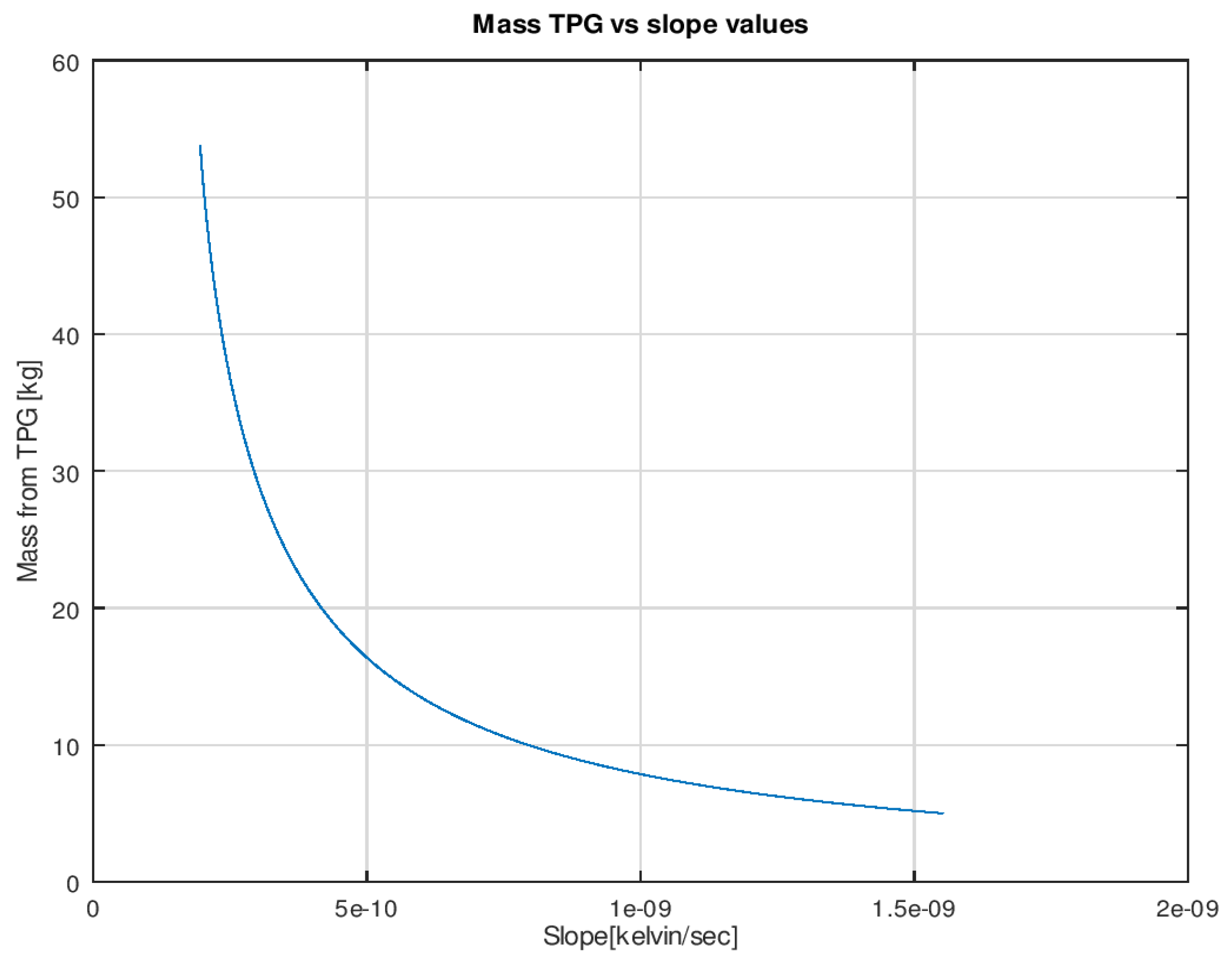
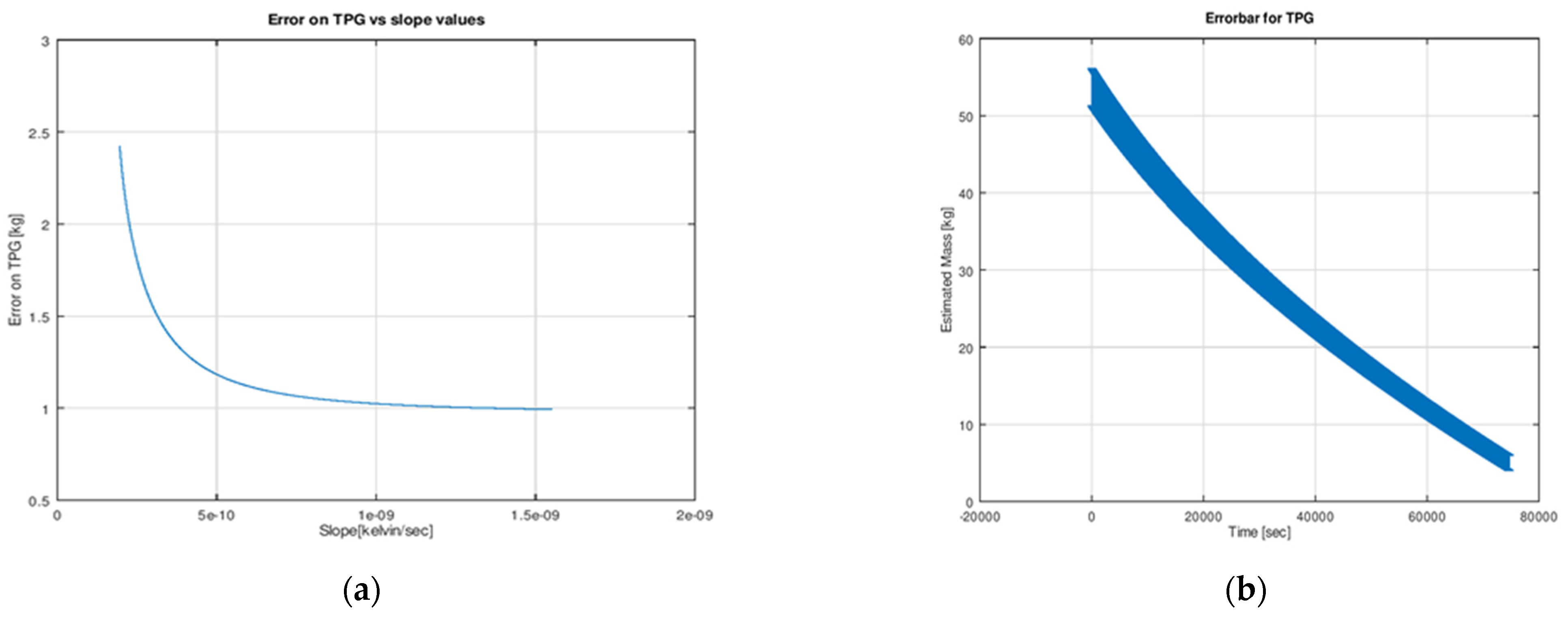
- Finally, the TPG method, which was the focus in this research work calculated the residual propellant mass from input and output heat transfer values from heaters and temperature sensors, respectively. This is an active/passive method of gauging which means heaters could be switched ON/OFF manually by giving a command from the ground station if necessary, and the change in temperature with respect to time for the tank should be acquired from telemetry data. Using temperature slopes, the residual mass can be calculated, and the models for this were developed in the project. The error contribution at the beginning was 0.7 kg (1.3%), whereas at the end, it was 1.02 kg (1.86%).
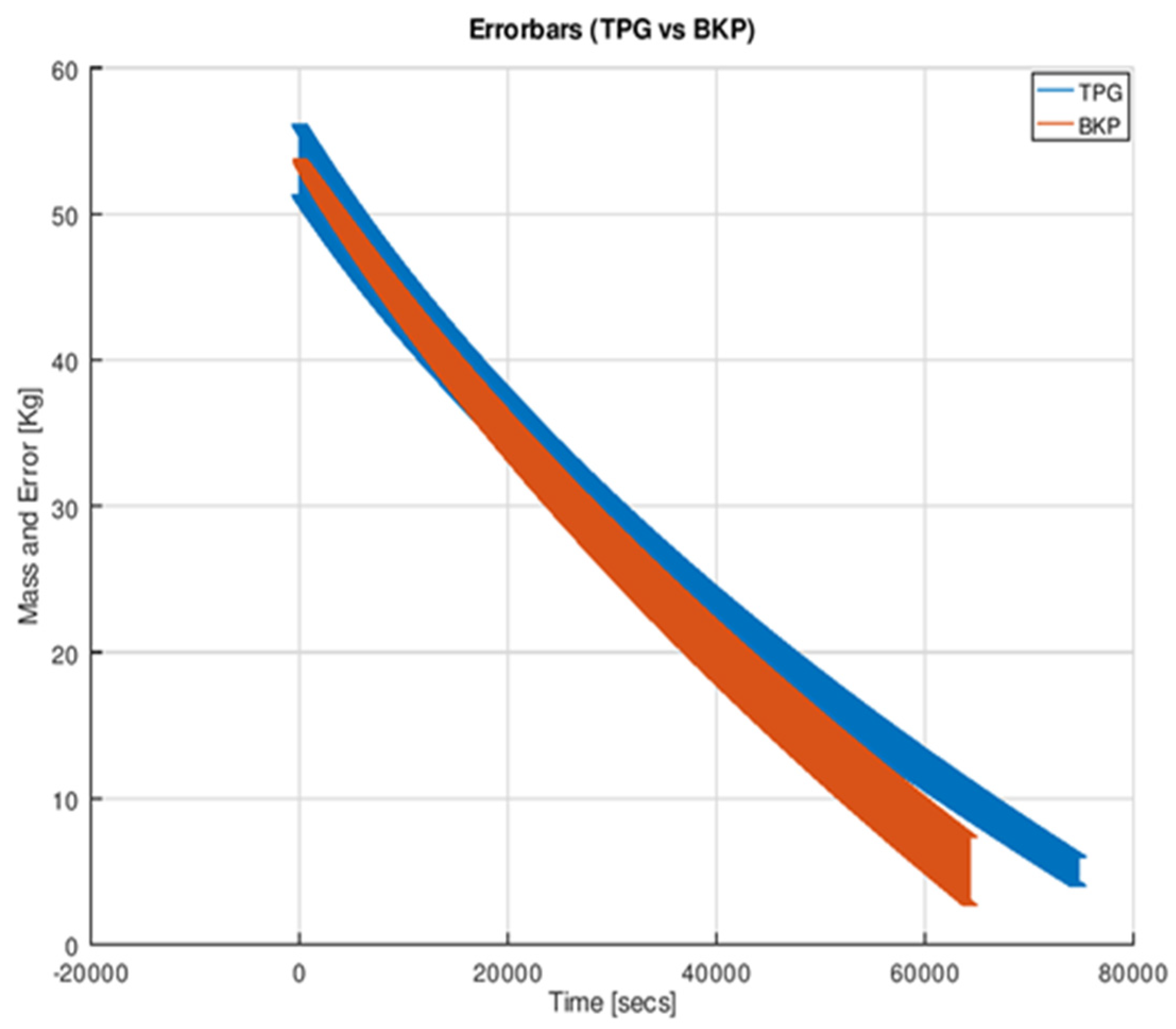
- Usually, the PVT method will be used by most of the satellites, but TPG exclusively developed here is giving better results than the other two methods at end of life. So, it was concluded to use two different methods for gauging the propellant in the satellite tank throughout its life.
- The duration up to which the BKP method can be used was also found. It was observed as 29,616 s up to which the BKP method provides better accuracy, and after this is recommended to shift to the TPG method for the tank fill level.
- Hence, developing the TPG model was more effective and will allow us to save 1.5 kg of propellant at the end of life which can add more ~5 months to the operational life of the satellite.
5. Conclusions
Author Contributions
Funding
Data Availability Statement
Acknowledgments
Conflicts of Interest
Nomenclature
| , , & | the specific heat constants for the mentioned subscripts respectively (J/KgK) |
| the heat capacity of the system (J/K) | |
| , , & | are the heat capacities as per the mentioned subscripts respectively (J/K) |
| & | the conduction constant for upper and lower interface respectively (W/m2K) |
| the total mass flow rate (in g/s) | |
| the relative error due to burnt propellant mass (in kg) | |
| the relative error due to helium pressure (in kg) | |
| the relative error due to initial temperature (in kg) | |
| the relative error due to mass flow rate (in kg) | |
| the relative error due to volume of pipe (in kg) | |
| the burnt propellant mass (in kg) | |
| the total error at time (t) | |
| the cumulative error due to variable parameters at time (t) | |
| the loaded mass (in kg) | |
| the mass available initially after loading (in kg) | |
| the relative error due to loaded mass (in kg) | |
| , , & | the masses as for the mentioned subscripts respectively (in kg) |
| the relative error due to sampling time (in kg) | |
| RSS | is the Root Sum Square |
| the helium pressure at the moment (in bar) | |
| the power of the heater (in W) | |
| P0 | the initial pressure of the pressurant (in bar) |
| & | the temperature of the upper and lower tank respectively (K) |
| the temperature of helium at the moment (in K) | |
| the external temperature of the tank (K) | |
| the working temperature on-board (in K) | |
| & | the temperature of the upper and lower blanker (K) |
| T0 | the initial temperature of the system (in K) |
| the volume of the propellant in the pipe at the moment (in L) | |
| the volume of the propellant in the pipe initially (in L) | |
| the volume of the propellant at the moment (in L) | |
| the volume of the propellant at initial time (in L) | |
| the wet pipe volume (in L) | |
| the ullage volume at the moment (in L) | |
| the ullage volume initially (in L) | |
| the propellant density, which is temperature dependent-only (in kg/L) | |
| the propellant density, at initial temperature ( (in kg/L) | |
| the average density considering min. and max. working temperatures (in kg/L) | |
| & i + 1 | the present and previous one |
| or t | the sampling time (in s) |
References
- Goff, J.; Zegler, F.; Bienhoff, D.; Marchetta, J.; Kutter, B.; Chandler, F. Realistic Near-Term Propellant Depots: Implementation of a Critical Spacefaring Capability. In Proceedings of the AIAA Space 2009 Conference & Exposition, Pasadena, CA, USA, 14–17 September 2009. [Google Scholar]
- NASA Technology Roadmaps TA 2: In-Space Propulsion Technologies. 2015. Available online: https://www.nasa.gov/sites/default/files/atoms/files/2015_nasa_technology_roadmaps_ta_2_in-space_propulsion_final.pdf (accessed on 2 February 2023).
- Yendler, B. Review of Propellant Gauging Methods. In Proceedings of the 44th AIAA Aerospace Sciences Meeting, Reno, NV, USA, 9–12 January 2006; American Institute of Aeronautics and Astronautics Inc.: Reston, VA, USA, 2006; Volume 15, p. 939. [Google Scholar] [CrossRef]
- Hufenbach, B.; Brandt, R.; Andre, G.; Voeten, R.; van Put, P.; Sanders, B.; Schwer, A.; Delil, A.; Mastenbroek, O.; Pauw, A. Comparative Assessment of Gauging Systems and Description of a Liquid Level Gauging Concept for a Spin Stabilized Spacecraft. In Proceedings of the Second European Spacecraft Propulsion Conference, Noordwijk, The Netherlands, 27–29 May 1997; ESA SP-287. European Space Agency: Paris, France, 1997. [Google Scholar]
- Hasan, D.; Jaeger, M.; Oren, A.; Adler, S.; Miller, N.; Zemer, E. Application of Satellite Hydrazine Propulsion System. In Proceedings of the 4th International Spacecraft Propulsion Conference (ESA SP-555), Chia Laguna (Cagliari), Sardinia, Italy, 2–9 June 2004. [Google Scholar]
- Dandaleix, L.; Ounougha, L.; Jallade, S. Flight Validation of Thermal Propellant Gauging Method. In Proceedings of the 4th International Spacecraft Propulsion Conference (ESA SP-555), Chia Laguna (Cagliari), Sardinia, Italy, 2–9 June 2004. [Google Scholar]
- Chobotov, M.V.; Purohit, G.P. Low-gravity propellant gauging system for accurate predictions of spacecraft end-of-life. J. Spacecr. Rocket. 1993, 30, 92–101. [Google Scholar] [CrossRef]
- Lal, A.; Raghunandan, B.N. Uncertainty analysis of propellant gauging system for spacecraft. J. Spacecr. Rocket. 2005, 42, 943–946. [Google Scholar] [CrossRef]
- Paros, J.M.; Purohit, G.P.; Clark, R.W. Satellite Propellant Gauging System Using High Resolution Quartz Pressure Transducers. In Proceedings of the 39th International Instrumentation Symposium, Albuquerque, NM, USA, 2–6 May 1993. [Google Scholar]
- Kowalek, J.; DASA/ERNO. A Liquid Volume Gauging System for Orbital applications. In Proceedings of the 1st ESA/CNES Spacecraft Propulsion Conference, Toulouse, France, 22–24 November 1994. [Google Scholar]
- Trinks, H.; Behring, T. Liquid Propellant Content Measurement Methods Applicable to Space Missions. In Proceedings of the 25th Joint Propulsion Conference, Monterey, CA, USA, 12–16 July 1989; American Institute of Aeronautics and Astronautics (AIAA): Washington, DC, USA, 1989. [Google Scholar] [CrossRef]
- Nariyoshi, R.; Chernikov, S.; Yendler, B.S. Prediction of Spacecraft Remaining Life-Challenges and Achievements. In Proceedings of the 49th AIAA/ASME/SAE/ASEE Joint Propulsion Conference, San Jose, CA, USA, 14–17 July 2013; American Institute of Aeronautics and Astronautics Inc.: Washington, DC, USA, 2013; Volume 1. [Google Scholar] [CrossRef]
- Ambrose, J.; Yendler, B.; Collicott, S.H. Modeling to evaluate a spacecraft propellant gauging system. J. Spacecr. Rocket. 2000, 37, 833–835. [Google Scholar] [CrossRef]
- Yendler, B. Unconventional Thermal Propellant Gauging System. In Proceedings of the 45th AIAA Aerospace Sciences Meeting, Reno, NV, USA, 8–11 January 2007; American Institute of Aeronautics and Astronautics Inc.: Washington, DC, USA, 2007; Volume 23, pp. 16155–16159. [Google Scholar] [CrossRef]
- Owens, B.; Cosgrove, D.; Sholl, M.; Bester, M. On-Orbit Propellant Estimation, Management, and Conditioning for the THEMIS Spacecraft Constellation. In Proceedings of the SpaceOps 2010 Conference, Huntsville, Al, USA, 25–30 April 2010. [Google Scholar] [CrossRef]
- Yendler, B.S.; Myers, M.; Chilelli, N.; Chernikov, S.; Wang, J.; Djamshidpour, A. Implementation of Thermal Gauging Method for ABS 1A (LM 3000) Satellite. In Proceedings of the SpaceOps 2016 Conference, Daejeon, Republic of Korea, 16–20 May 2016; American Institute of Aeronautics and Astronautics Inc.: Washington, DC, USA, 2016. [Google Scholar] [CrossRef]
- Benthem, R.C.; van Es, J.; van Put, P.; Matthijssen, R. Accuracy Analysis of Propellant Gauging Systems. In Proceedings of the 43rd International Conference on Environmental Systems (ICES), Vail, CO, USA, 14–18 July 2013; p. 3300. [Google Scholar] [CrossRef]
- Brauer, L.E.; Chun, S.H.; Davies, K.; Pulkowski, J.A. Method fa Measuring the Mass of Liquid in a Storage Tank. US Patent 5,158,362, 27 October 1992. [Google Scholar]
- Yendler, B.S.; Molinsky, J.; Chernikov, S.; Guadagnoli, D. Comparison of Gauging Methods for Orbital’s GEOstarTM1 Satellites. In Proceedings of the 13th International Conference on Space Operations, SpaceOps 2014, Pasadena, CA, USA, 5–9 May 2014; American Institute of Aeronautics and Astronautics Inc.: Washington, DC, USA, 2014. [Google Scholar] [CrossRef]
- Chang, Y.; Chae, Y.; Young, M.; Han, H. Error Analysis of Spacecraft Propellant Gauging Techniques. In Proceedings of the 30th AIAA/ASME/SAE/ASEE Joint Propulsion Conference, Indianapolis, IN, USA; American Institute of Aeronautics and Astronautics (AIAA): Washington, DC, USA, 1994. [Google Scholar] [CrossRef]
- Brouard, L.; Ounougha, L.; Jallade, S. Propellant Gauging Method on Astrum SAS. In Proceedings of the 3rd International Conference on Spacecraft Propulsion, Cannes, France, 10–13 October 2000; ESA SP-465. European Space Agency: Paris, Frence, 2000. [Google Scholar]
- Loizzo, R.; Guarini, R.; Longo, F.; Scopa, T.; Formaro, R.; Facchinetti, C.; Varacalli, G. PRISMA: The Italian hyperspectral mission. In Proceedings of the IGARSS 2018-2018 IEEE International Geoscience and Remote Sensing Symposium, Valencia, Spain, 22–27 July 2018; pp. 175–178. [Google Scholar]
- Pignatti, S.; Palombo, A.; Pascucci, S.; Romano, F.; Santini, F.; Simoniello, T.; Umberto, A.; Vincenzo, C.; Acito, N.; Diani, M. The PRISMA hyperspectral mission: Science activities and opportunities for agriculture and land monitoring. In Proceedings of the 2013 IEEE International Geoscience and Remote Sensing Symposium-IGARSS, Melbourne, VIC, Australia, 21–26 July 2013; pp. 4558–4561. [Google Scholar]
- Shaik, R.U.; Periasamy, S.; Zeng, W. Potential Assessment of PRISMA Hyperspectral Imagery for Remote Sensing Applications. Remote Sens. 2023, 15, 1378. [Google Scholar] [CrossRef]
- Shaik, R.; Laneve, G.; Fusilli, L. An Automatic Procedure for Forest Fire Fuel Mapping Using Hyperspectral (PRISMA) Imagery: A Semi-Supervised Classification Approach. Remote Sens. 2022, 14, 1264. [Google Scholar] [CrossRef]
- Shaik, R.; Giovanni, L.; Fusilli, L. Dynamic Wildfire Fuel Mapping Using Sentinel–2 and Prisma Hyperspectral Imagery. In Proceedings of the IGARSS 2022–2022 IEEE International Geoscience and Remote Sensing Symposium, Kuala Lumpur, Malaysia, 17–22 July 2022; pp. 5973–5976. [Google Scholar]
- Thangavel, K.; Spiller, D.; Sabatini, R.; Amici, S.; Sasidharan, S.T.; Fayek, H.; Marzocca, P. Autonomous Satellite Wildfire Detection Using Hyperspectral Imagery and Neural Networks: A Case Study on Australian Wildfire. Remote Sens. 2023, 15, 720. [Google Scholar] [CrossRef]
- Thangavel, K.; Spiller, D.; Sabatini, R.; Amici, S.; Longepe, N.; Servidia, P.; Marzocca, P.; Fayek, H.; Ansalone, L. Trusted Autonomous Operations of Distributed Satellite Systems Using Optical Sensors. Sensors 2023, 23, 3344. [Google Scholar] [CrossRef] [PubMed]
- Lal, A.; Raghunandan, B.N. Configuration for Propellant Gauging in Satellites. J. Spacecr. Rocket. 2007, 44, 143–146. [Google Scholar] [CrossRef]
- Eaton, J.W.; Bateman, D.; Hauberg, S. Gnu Octave; Network Theory: London, UK, 1997. [Google Scholar]
- Alberts, C.; Dorofee, A.; Stevens, J.; Woody, C. Introduction to the OCTAVE Approach; Carnegie-Mellon Univ Pittsburgh Pa Software Engineering Institute: Pittsburgh, PA, USA, 2003. [Google Scholar]


| Parameters | Input Values | Values Type | Associated Error | Units |
|---|---|---|---|---|
| 53.70 | Measured at fueling | Kg | ||
| 0.109 | Calculated [CAD & supplier data] | L | ||
| 293.15 | Measured at fueling | K | ||
| 1.102 (BoL) | Calculated at initial helium pressure and burnt mass | kg/s | ||
| 0.567 (EoL) | ||||
| 21.6 (BoL) | Measured at fueling (BoL) | bar | ||
| 11.0 (EoL) | Calculated (EoL) | |||
| t | 2 | Data sampling time | s | |
| 21.59 | Measured at fueling | Bar | ||
| 103.2 | From supplier data | L | ||
| T | 283.15–323.15 | Allowed range in orbit | K | |
| 10 | From supplier data | W |
| Parameters | Relative Error Model | Absolute Error Models | |
|---|---|---|---|
| Constant errors | Propellant loaded mass ( | ||
| Volume of the pipe ( | |||
| Initial Temperature ( | |||
| Variable errors | Mass flow rate ( | ||
| Helium Pressure ( | |||
| Burnt mass () | |||
| Sampling time (t) |
| Parameters | Relative Error Model | |
|---|---|---|
| Relative Error | Absolute Error | |
| Parameter | Consideration | Error |
|---|---|---|
| PWR |
| Method | Estimated Error (kg) | Error Percentage (%) |
|---|---|---|
| BoL EoL | BoL EoL | |
| BKP | 0.1 2.5 | 0.1 4.6 |
| PVT | 0.6 2.6 | 1.0 4.8 |
| TPG | 0.7 1.0 | 1.3 1.8 |
Disclaimer/Publisher’s Note: The statements, opinions and data contained in all publications are solely those of the individual author(s) and contributor(s) and not of MDPI and/or the editor(s). MDPI and/or the editor(s) disclaim responsibility for any injury to people or property resulting from any ideas, methods, instructions or products referred to in the content. |
© 2023 by the authors. Licensee MDPI, Basel, Switzerland. This article is an open access article distributed under the terms and conditions of the Creative Commons Attribution (CC BY) license (https://creativecommons.org/licenses/by/4.0/).
Share and Cite
Shaik, R.U.; Relangi, N.; Thangavel, K. Mathematical Modelling of a Propellent Gauging System: A Case Study on PRISMA. Aerospace 2023, 10, 567. https://doi.org/10.3390/aerospace10060567
Shaik RU, Relangi N, Thangavel K. Mathematical Modelling of a Propellent Gauging System: A Case Study on PRISMA. Aerospace. 2023; 10(6):567. https://doi.org/10.3390/aerospace10060567
Chicago/Turabian StyleShaik, Riyaaz Uddien, Naresh Relangi, and Kathiravan Thangavel. 2023. "Mathematical Modelling of a Propellent Gauging System: A Case Study on PRISMA" Aerospace 10, no. 6: 567. https://doi.org/10.3390/aerospace10060567
APA StyleShaik, R. U., Relangi, N., & Thangavel, K. (2023). Mathematical Modelling of a Propellent Gauging System: A Case Study on PRISMA. Aerospace, 10(6), 567. https://doi.org/10.3390/aerospace10060567


