Abstract
Hot fire tests of a multi-injector research combustor were performed with liquid-oxygen and liquefied-natural-gas (LOX/LNG) propellants at chamber pressures from 30 up to 67 bar, hence at conditions similar to an upper stage rocket engine. Within these tests shear coaxial injectors were tested with and without a recessed LOX post. In both configurations, operating conditions with flames anchored at the LOX post tip and thus, if available, pre-combustion in the recess volume as well as lifted flames were observed. Flame anchoring was indirectly detected via acoustic measurements, using mean speed of sound to indicate the presence of flame in the head end of the combustion chamber. While the injector without recess showed only stable combustion irrespective of the flame anchoring behavior, the recessed injector featured short-lived bursts of oscillatory combustion and sustained combustion instabilities. Analysis of the test data showed that stable flame anchoring could not be ensured at momentum flux ratios below 20 for a non-recessed and below 45 for a recessed injector.
1. Introduction
Future space missions with new mission profiles and different requirements to the propulsion system require the development of new rocket engines. The propellant combination of liquid oxygen and methane (LOX/CH) is predicted to be a economically competitive alternative to oxygen/hydrogen (LOX/H).
The combustion behavior as well as the overall performance of liquid propellant rocket engines (LPREs) are significantly influenced by the injector. Its design determines the atomization and mixing of the propellants. A prominent injector technology choice for propellant combinations with a high density ratio (e.g., liquid and gaseous combination) between oxidizer and fuel is a coaxial element [1]. This element type consists of a central tube surrounded by an annulus enabling both propellants to enter the combustion chamber coaxially. This type can be further distinguished by liquid or gaseous fluids being injected through the central tube, thus liquid-centered or gaseous-centered coaxial elements. Here gaseous centered coaxial injectors with a tuned element length can mitigate the combustion chamber’s vulnerability to longitudinal combustion instabilities [2]. Additional swirling of one or both propellant components (swirl-coaxial injector) can improve the mixing characteristics. This work focuses on the use of unswirled liquid-centered coaxial elements (shear-coaxial injector) for LOX/CH, which are primarily used in LOX/H rocket engines [1].
The slower reaction kinetics in LOX/CH combustion compared with LOX/H [3,4] give rise to the potential for a different flame anchoring behavior. While flame anchoring at the LOX post tip has consistently been observed for shear coaxial LOX/H injection [5,6,7,8], flame anchoring in the shear layer further downstream is a possible mechanism with LOX/CH [3,9,10]. This adds another source of uncertainty to the combustion characteristics of a rocket engine.
Yang [3] reported on lifted flames for subcritical LOX/CH flames at similar conditions, where a stable flame anchoring, with the flame’s origin at the LOX post tip, was observed for LOX/H flames. Intermittent lifted flames at supercritical pressures for liquid-oxygen/compressed-natural-gas combustion were observed as well in an optical accessible combustion chamber [10]. Preliminary analysis of the flame anchoring behavior, with the same experimental setup as analyzed in this work, and its effect on the combustation stability is provided in a previous publication [9]. While during stable combustion the cooling of the injected LOX and LNG is sufficient to prevent the injector from being damaged in spite of a flame anchoring at the LOX post tip, this was not the case for the high-amplitude combustion instabilities. Here, the increased temperature in the vicinity of the injection plane thermally damaged the injectors.
This work reports on flame anchoring behavior observed in a multi-injector research combustor with liquid-oxygen/liquefied-natural-gas (LOX/LNG) propellants operating at conditions similar to an upper-stage rocket engine. Within the framework of the presented test campaign two different injector configurations (with and without recess) were tested. It should be noted here that characterization of an injector optimized for LOX/Hydrogen combustion for the propellant combination LOX/LNG was a secondary goal of the campaign. During these tests different variants of flame anchoring and dynamics in the form of high frequency combustion instabilities were observed. Through the analysis of the measurements in the injection manifolds in combination with the given geometry it will be shown that the observations of the flame anchoring character are best explained by the momentum flux ratio (J) and the level of thermoacoustic oscillations.
In this paper, the experimental conditions will first be described under which the different types of flame anchoring mechanisms were observed. Following this the momentum flux ratio as a key factor for determining the flame anchoring behavior is presented. Finally, the influence of the combustion stability as a secondary factor on the flame anchoring behavior will be discussed.
2. Experimental Method
2.1. Thrust Chamber
The hot-fire tests analyzed in this work were conducted at the European Research and Technology Test Facility P8 for cryogenic rocket engines with the DLR research thrust chamber model ‘D’ (BKD) [11]. BKD consists of a multi-element injector head, a measurement ring, at least one cylindrical chamber segment and a convergent divergent nozzle. For these tests it was configured with two cylindrical chamber segments resulting in an overall length of 400 mm. The combustor configuration is illustrated in Figure 1.
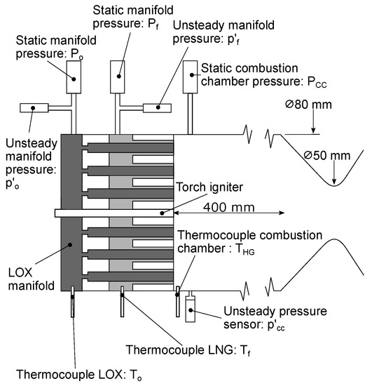
Figure 1.
Experimental thrust chamber (schematic) [9].
The oxidizer (LOX) and fuel (LNG) manifolds are equipped with static pressure sensors (, ) and thermocouples (, ) sampled at a frequency of 100 Hz to determine the thermodynamic state of the injectants. The measurement ring mounted between the injector head and the first chamber segment is instrumented with four unsteady pressure sensors at the circumferential angular positions of 0°, 80°, 180°, and 300°. The sample rate of the signal is 100 kHz. The measurement range was set to bar. 20 thermocouples in groups of five distributed 90° apart () measuring the hot gas temperature in the vicinity of the wall were installed in the measurement ring. Additional information on the boundary conditions in the chamber is provided by a static pressure sensor (). Both the temperature and the static pressure measurement are sampled with a rate of 100 Hz. LOX and LNG are injected through 42 shear coaxial injection elements with a tapered LOX post, as illustrated in Figure 2 and an inner (exit) diameter of the LOX posts of mm, a tip width of 0.15 mm and a size of the annular gap of 0.5 mm. Tests with a recess of 2 mm, or 0.54 d, and without recess were conducted.
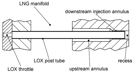
Figure 2.
Experimental chamber injection element [12].
2.2. Operating Conditions
Data from eight tests distinguished in 21 load points (LPs) are analyzed in this work. The LPs are defined by the chamber pressure and ratio of oxidizer to fuel mass flow rate (ROF) in Table 1. This table also contains additional information on the combustion stability, whether the flame was lifted and if a recessed injector was used.

Table 1.
Overview of test runs. (✓ = Yes; ✗ = No; ✓/✗ = Both).
The tests were conducted with chamber pressures up to 67 bar and ROF up to 2.7. This results in a thermal power of up to approximately 60 MW. The LNG injection temperature was determined by the heat transfer from the combustion chamber to the regenerative cooling. A stable LNG injection mass flow was maintained by a closed-loop regulation. Two tests are presented in Figure 3 and Figure 4. Figure 3 represents a typical run with recessed injector and Figure 4 without recessed injector. The test sequences are described with spectrograms (top) of the unsteady pressure signal (middle), along with traces of the static chamber pressure , LOX injection temperature , LNG injection temperature , and ROF (bottom). These traces of parameters describe the performed sequence of operating conditions, while the raw unsteady pressure signal (middle) and the spectrogram (top) describe the stability character. It should be noted that the unsteady pressure signals partially exceed their measurement range during phases of high amplitude instabilities.
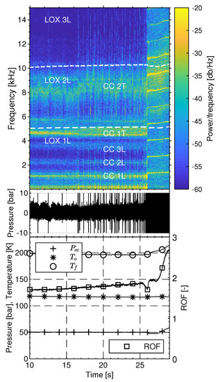
Figure 3.
Test sequence with operating conditions (bottom), unsteady pressure trace (middle), and spectrogram from unsteady pressure (top) for Test C with recessed injector [9].
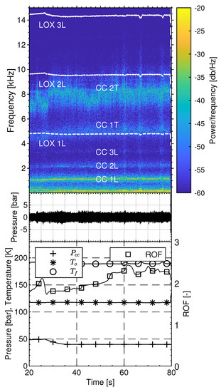
Figure 4.
Test sequence with operating conditions (bottom), unsteady pressure trace (middle), and spectrogram from unsteady pressure (top) for Test F with non-recessed injector.
3. Methodology
Lifted Flame Detection
A key aspect during analysis of the flame anchoring behavior in this work was the identification whether the flame is lifted or anchoring at the LOX post tip. Since no optical probes were available in the measurement ring for these tests an alternative approach for the identification of the flame’s anchoring location has to be applied. An essential element in the flame anchoring detection are the different characteristics of a lifted and anchored flame. In the latter case the flame’s origin is directly at LOX post tip. The mixture of heated propellants, in the vicinity of the flame, and burnt combustion gases result in a higher mean temperature at the head end of the combustion chamber and a rapidly increasing speed of sound. In case of lifted flame the propellants enter the combustion chamber and begin reacting further downstream. The cooler mean temperature near the injection plane results also in an initially lower speed of sound compared to the anchored case. The detection method used in this work based upon the approach developed in previous work [9] and consists of three steps.
The first step uses Equation (1) [13] to estimate the frequencies f of the first and second tangential mode (1T, 2T), since these modes are most affected by a lifted flame:
This is a modified version of the analytic equation for linear acoustic eigenmodes in a cylindrical volume, accounting for the axial distribution of the sound speed with correction factors for the influence on longitudinal modes and for transverse modes. Figure 5 shows a typical radially averaged axial speed of sound profile for LOX/CH combustion. A zone of reduced speed of sound can be seen upstream of the final plateau where chemical equilibrium is reached. This zone is characterized by the mixing and combustion processes [13]. As the transverse modes usually occur in the region close to the injector, is mostly influenced by the speed of sound at the upstream end of the chamber. Therefore is calculated according to Equation (2) as the ratio of the averaged speed of sound in the mixing and combustion zone () to the equilibrium sound speed provided by CEA ().
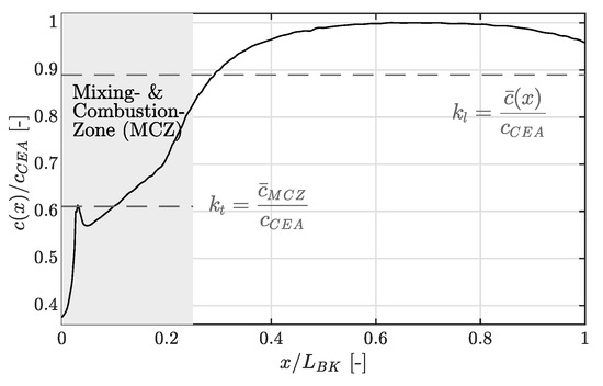
Figure 5.
Typical radially averaged and normalized speed of sound profile of a LOX/CH combustion chamber, based upon [14].
Longitudinal modes and thus are affected by the speed of sound throughout the whole chamber. is thus calculated according to Equation (3) as the ratio of the averaged speed of sound () to the equilibrium sound speed provided by CEA ().
The regions of interest for both correction factors are indicated by dotted lines in Figure 5. Based upon the hardware configuration used and the operating conditions achieved (considering a nominal combustion behavior) in these experiments the longitudinal correction factor and the transverse correction factor were calculated as 0.88 and 0.61, respectively. The variable is the equilibrium sound speed in the combustion chamber calculated by NASA CEA [15] dependent on the combustion efficiency . Here, D is the diameter and L the length of the chamber, m, n, and q are integer variables for radial, transverse, and longitudinal modes, respectively, and is the m-th root of the radial derivation of the nth order Bessel function of first kind divided by . Finally, a correction for the influence of axial flow through the chamber is performed with the mean Mach number in the combustor . For example, considering a nominal and stable combustion behavior Equation (1) provides frequencies between 4862 and 4975 Hz for the 1T mode and frequencies between 8050 and 8240 Hz for the 2T mode in Test F.
The second step compares the calculated tangential modes with those extracted from test data for each LP. If a significant decrease (at least 300 Hz) in the experimental frequency compared to the calculated is detected, a closer look at the temperature measurements in the measurement ring was taken. A lowered frequency of the acoustic resonance modes in the chamber indicates a reduced mean sound speed in the chamber caused by an increased cold-zone at the upstream end near the faceplate an thus a lifted flame. Previous analysis [9] has shown that, even if combustion instabilities occured, the temperature near the faceplate stays constant for a flame anchoring at the LOX post tip (Figure 6) and is clearly reduced for a lifted flame (Figure 7).
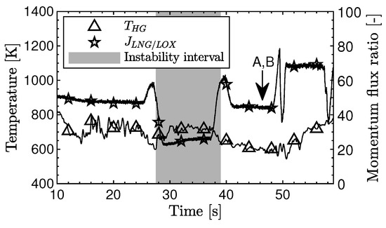
Figure 6.
Combustion chamber gas-side temperature at the measurement ring, and momentum flux ratio at the injection element for Test A [9].
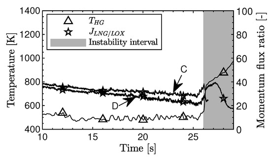
Figure 7.
Combustion chamber gas-side temperature at the measurement ring, and momentum flux ratio at the injection element for Test C [9].
The third step consolidates the previous steps with recalculating the transversal modes according to Equation (1) with an adjusted correction factor considering a lifted flame. As previously stated, is mainly influenced by speed of sound upstream of the final plateau in the profile. A lifted flame is approximated by extending the cold-zone at the head end of the chamber. In case of a lifted flame the calculation of also considers the extended cold-zone and is modified according to Equation (4).
Here is the ratio of the averaged speed of sound throughout the extended cold-, mixing- and combustion zone to the speed of sound by CEA assuming chemical equilibrium. An enlargement of the cold-zone leads to a reduction of . For an estimation of the lift-off distance the cold-zone is extended in an iterative process until the resulting in combination with Equation (1) matches the experimental measured frequency. The distance of the cold-zone extension equals the estimated lift-off distance. The adjusted speed of sound profile with an extended cold-zone and the adjusted correction factors is visualized in Figure 8. Again, the regions of interest for the calculation of these factors are indicated by dotted lines.
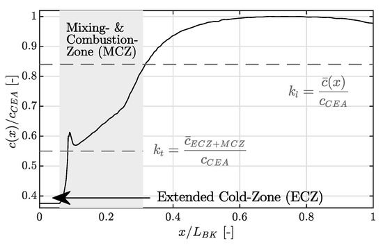
Figure 8.
Typical radially averaged and normalized speed of sound profile of a LOX/CH combustion chamber, based upon [14], with an extended cold-zone as approximation for a lifted flame.
The three steps are visualized in Figure 9 for Test F. However, consistent behavior regarding a reduced temperature near the injection plane and reduced frequencies of the resonance modes in the chamber and thus consistent judgment of a lifted flame was possible.
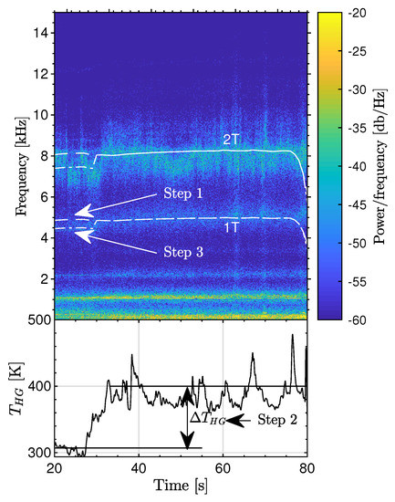
Figure 9.
Spectrogram from unsteady pressure (top) with averaged temperature in measurement ring (bottom) for Test F.
Here, for the sub-/transcritical LP F.1 a lift-off distance of 30 mm reducing by 0.06 applies to match the experimental frequency. The same reduction of the transversal correction factor also applies for the other sub-/transcritical LPs with lifted flames C.1 and D.1. The supercritical LPs G.1, G.2, H.1 and H.2 required a lift-off distance of 60 mm accompanied by a reduction of by 0.1 to fit the experimental frequency. It should be noted here, that the recalculation of the resonance frequencies in the chamber according to Equation (1) with reduced correction factors considering an extended cold-zone due to a lifted flame is a simplified assessment of the lift-off distance. The calculated lift-off distances should be interpreted as estimations.
4. Results and Discussion
The flame anchoring behavior will now be examined.
Figure 10 shows the pressure drop between fuel manifold () and combustion chamber () plotted against the pressure drop from the oxygen manifold () to the combustion chamber () for the tests A–D with recessed injectors. The pressure drop values are normalized by the chamber pressure. It can be observed that the load points, which were identified to have a lifted flame due to the lifted flame detection procedure, also have a lower pressure drop for the fuel injection. The LOX pressure drop is unaffected by flame anchoring location [9].
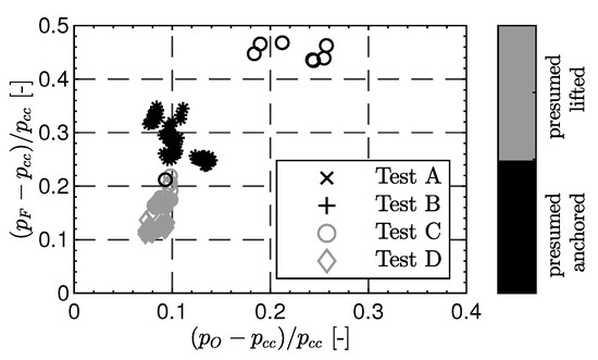
Figure 10.
Pressure drop between dome volumes and combustion chamber for tests A–D with respect to the assumed flame anchoring mechanism for a recessed injector. (Modified from [9]; Shapes indicate Test, Colors indicate presumed flame anchoring mechanism).
Figure 11 visualizes the pressure drops of the fuel and oxygen over the injectors, but for non-recessed injector configuration. Again, the samples featuring a lifted flame, as identified by the lifted flame detection procedure, have the lowest pressure drop on the fuel side. Although there are data points at similar fuel pressure drop but not identified as lifted flame, these are characterized by a significantly lower oxygen pressure drops indicating a LP with reduced chamber pressure. At lower chamber pressures also the percentage of pressure drop over the injection system decreases. It can also be seen that in case of a non-recessed injector the pressure drop over the fuel annulus is lower in general. At normalized oxygen pressure drop values of ≈0.1 normalized fuel pressure drop values down to ≈0.15 were observed. In case of a recessed injector configuration such low fuel pressure drops were only observed with a lifted flame. This can be explained by the observations from Kendrick et al. [16] and Schmitt [17]. They showed that a recessed injector leads to acceleration of the annular fuel flow as it is pinched by the flame expanding inside the recess region, and therefore an increase in fuel injection velocity and pressure drop over the fuel injection.
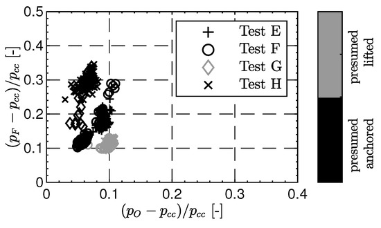
Figure 11.
Pressure drop between dome volumes and combustion chamber for tests E–H with respect to the assumed flame anchoring mechanism for a non-recessed injector. (Shapes indicate Test, Colors indicate presumed flame anchoring mechanism.).
Based upon the data presented in Table 1 some preliminary correlations can already be found. First of all it can be clearly seen that all LPs from test runs without a recessed injector showed stable combustion. More precisely the injection element without recess showed stable combustion for both lifted and anchored flames. Solely test runs with a recessed injector showed unstable combustion with high amplitude pressure oscillations. Here LPs with short-lived pressure bursts of oscillatory combustion and LPs with sustained combustion instabilities were observed. A more detailed analysis of the these combustion instabilities is provided in a previous work [9].
The momentum flux ratio (J-number) plays an important role in models describing the forces which govern the primary breakup of the LOX jet in shear coaxial injectors [18,19,20]. Higher values of J enhance the mixing processes between oxidizer and fuel [21]. Thus, the influence of the momentum flux ratio, calculated according to Equation (5), on the flame anchoring mechanism will be investigated.
Here and u denote the density and injection velocity of the injectants, respectively, with the subscript F for LNG and O for LOX.
Figure 12 shows the momentum flux ratio of the injectants with respect to the chamber pressure distinguished by flame anchoring mechanism for the tests in which a non-recessed injector was used. The threshold setting the minimum value to be necessary for an anchored flame seems to be a J number between 18 and 20.
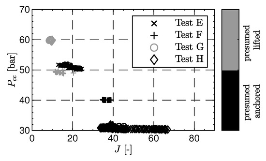
Figure 12.
Momentum flux ratio of the injectants with respect to the chamber pressure distinguished by flame anchoring mechanism for a non-recessed injector (Tests E–H; Shapes indicate Test, Colors indicate presumed flame anchoring mechanism).
Figure 13 plots the momentum flux ratio of the injectants against the thermoacoustic amplitude normalized by the chamber pressure, again distinguished by flame anchoring mechanism, for the tests in which a non-recessed injector was used. Here it can be seen that a stable lifted flame showed consistently lower levels of thermoacoustic activity. In the case of an anchored flame normalized thermoacoustic amplitudes approaching these of harming high-frequency combustion instabilities (5%) could be observed.
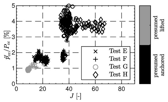
Figure 13.
Momentum flux ratio of the injectants with respect to the normalized unsteady pressure amplitude distinguished by flame anchoring mechanism for a non-recessed injector (Tests E–H; Shapes indicate Test, Colors indicate presumed flame anchoring mechanism).
The relation between the momentum flux ratio and the flame anchoring mechanism for a recessed injector draws a more complex picture (Figure 14).
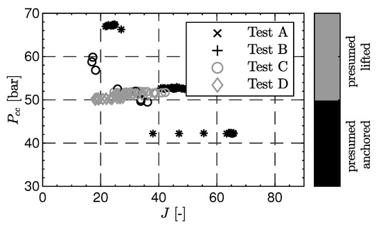
Figure 14.
Momentum flux ratio of the injectants with respect to the chamber pressure distinguished by flame anchoring mechanism for a recessed injector (Tests A–D; Shapes indicate Test, Colors indicate presumed flame anchoring mechanism).
At a of 50 bar, the threshold for a recessed injector is at a J-value of 45. However, there also exist LPs at higher pressure and lower momentum flux ratio featuring flame anchoring at the LOX post tip.
Clarification is provided by (Figure 15), which again compares the momentum flux ratio and flame anchoring mechanism with the normalized thermoacoustic amplitude. Here it can be seen that the LPs, where flame anchoring at the LOX-post tip for low momentum flux ratios was observed, are extracted from intervals characterized by high amplitude combustion instabilities. In other words, there were no lifted flames observed during oscillatory combustion. Either the combustion instability causes the flame to anchor at the injector, or the anchoring facilitates the conditions for combustion instability. In a previous work the LPs originating from LP A.2/B.2 were identified as a resonance of the chamber’s first tangential resonance (1T) mode and these from LP C.2/E.1 were identified as a resonance of the chamber’s first longitudinal mode (1L) [9]. In these cases it is supposed that the possible degradation in anchoring from a low J-number is counteracted by the strong transverse velocity perturbations near the faceplate of the 1T and 1L mode enhancing the primary jet breakup and mixing process. The impact on the fuel-mixture process by means of a retracted LOX core during instabilities was shown by Hardi et al. [22].
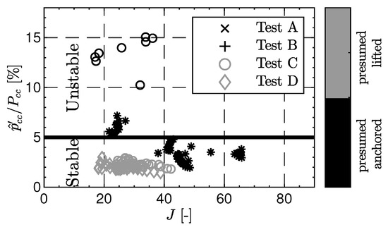
Figure 15.
Momentum flux ratio of the injectants with respect to the normalized unsteady pressure amplitude distinguished by flame anchoring mechanism for a recessed injector (Tests A–D; Shapes indicate Test, Colors indicate presumed flame anchoring mechanism).
While for a non-recessed injector all LPs resulting in are characterized by a flame anchoring at the LOX post tip, a lifted flame applies for with a recessed injector and stable combustion. Since combustion instabilities could solely be observed in the recessed injector configuration this leads to the conclusion that the LOX post recess somehow influences the flame dynamics in an unfavorable way. This conclusion contradicts the conventional wisdom on the design of shear coaxial injectors for LOX/H saying that recess has a stabilizing influence on combustion instabilities, although this may be limited to the transverse modes [23]. Schmitt [17] compared simulations of a recessed and non-recessed LOX/H injector and found that the heat release rate near the injector is doubled for the recessed case and pointed out its importance for the flame acoustic interaction with respect to combustion instabilities. In addition he also observed hydrodynamic footprints of the inner stream are more prominent on the annular stream in form of velocity perturbations in case of a recessed injector, introducing a periodically oscillating heat release rate. These dynamics of a recessed injector can play an important role in developing combustion instabilities. The slower reaction kintetics in LOX/CH combustion compared with LOX/H result in a stronger axial variation of the heat release [24]. This axial variation of the heat release rate is even more prominent with the flame translation between a flame anchored at the LOX post tip and further downstream. The aforementioned dynamics for recessed injectors in combination with the different combustion characteristics for LOX/CH could play a role in the greater susceptibility of recessed LOX/LNG injectors to combustion instabilities.
In summary the flame anchoring characteristics can be divided into three regimes with respect to the momentum flux ratio among both injector configurations. The first J-number regime is below a value of 20 and is characterized by a stable lifted flame. This is valid for both injector configurations, although data regarding a recessed injector is rare in this regime. The second regime is valid for both injector types as well and above a value of 45 and is marked by a stable anchored flame at the LOX post tip. J-numbers between 20 and 45 result in an stable anchored flame for the injector without recess and an unstable anchored/lifted flame for the recessed injector. Since the non-recessed injector showed stable anchoring at the LOX post tip for similar operating condition it is possible that the higher relative injection velocities in the recessed version might exceed the flame propagation speed and cause it to lift. This could further provide an explanation why combustion instabilities only occurred for the recessed injector configuration. J-value above 20 seems to be sufficient to provide stable flame anchoring as seen in the data of an injector without recess. However, the higher LNG injection velocity due to the recessed injector prevents the flame to anchor robustly at the LOX-post tip. These two dynamics opposing each other lead to unstable flame anchoring, introducing flame translation of the flame anchoring position axially between the LOX post tip and some position downstream in the shear layer and perturbations to the combustion and thus setting boundary conditions enabling the development of high-amplitude combustion instabilities.
5. Conclusions
Thee different types of flame anchoring behavior occurring in a sub-scale LOX/LNG rocket thrust chamber with and without recessed injectors were analyzed in this work.
The first behavior was a stable lifted flame and was detected for both injector configurations below a threshold for the momentum flux ratio of approximately 20. The second behavior was a stable anchored flame and occurred at values for the momentum flux ratio above 20 for the non-recessed injector and 45 for the recessed injector. The third flame anchoring behavior corresponded to an unstable anchored/lifted flame along with the occurrence of combustion instabilities and could be observed for the recessed injector configurations between momentum flux ratios of 20 and 45.
The latter behavior was hypothesized to be caused by the high J-numbers theoretically sufficient for stable flame anchoring and the increased fuel injection velocity due the pinched fuel flow area inside the recess opposing each other.
One important aspect of the current observations is that the injector without LOX post recess was stable whereas two types of instability occurred with the recessed injector. This is in contradiction with conventional wisdom on the design of shear coaxial injectors for LOX/H in which recess has a stabilizing influence on combustion instabilities.
Author Contributions
Conceptualization, J.H.; Methodology, J.M., J.H. and M.O.; Software, J.M.; Validation, J.M.; Formal Analysis, J.M. and M.B.; Investigation, J.M., M.B. and D.S.; Resources, J.H.; Writing—Original Draft Preparation, J.M.; Writing—Review & Editing, J.M., M.B., J.H., D.S. and M.O.; Visualization, J.M.; Supervision, J.H. and M.O.; Project Administration, J.H.; Funding Acquisition, J.H. All authors have read and agreed to the published version of the manuscript.
Funding
This research received no external funding.
Institutional Review Board Statement
Not applicable.
Informed Consent Statement
Not applicable.
Acknowledgments
The work is associated with the Franco-German Rocket Engine Stability iniTiative (REST). The authors would also like to thank the crew of the P8 test bench. Thanks also to Jan Haemisch in performing and Alex Grebe for their assistance in performing the experiments.
Conflicts of Interest
The authors declare no conflict of interest.
References
- Schmidt, G. Flames: Technik der Flüssigkeits-Raketentriebwerke; DaimlerChryslerAerospace: Munich, Germany, 1999. [Google Scholar]
- Wang, Y.; Cho, C.H.; Du, J.; Sohn, C.H. Effects of recess length on combustion instability in a model chamber with a gas-centered swirl coaxial injector. Aerosp. Sci. Technol. 2022, 130, 107911. [Google Scholar] [CrossRef]
- Yang, B.; Cuoco, F.; Oschwald, M. Atomization and Flames in LOX/H2- and LOx/CH4- Spray Combustion. J. Propuls. Power 2007, 23, 763–771. [Google Scholar] [CrossRef]
- Fiock, E.F. Measurement of Burning Velocity. In Physical Measurements in Gas Dynamics and Combustion; Ladenburg, R., Lewis, B., Pease, R., Taylor, H.S., Eds.; Princeton University Press: Princeton, NJ, USA, 1953; pp. 409–438. [Google Scholar]
- Mayer, W.; Smith, J. Fundamentals of Supercritical Mixing and Combustion of Cryogenic Propellants. In Liquid Rocket Thrust Chambers; Popp, M., Hulka, J., Yang, V., Habiballah, M., Eds.; American Institute of Aeronautics and Astronautics: Reston, VA, USA, 2004; pp. 339–367. [Google Scholar]
- Herding, G.; Snyder, R.; Scouflaire, P.; Rolon, C.; Candel, S. Flame Stabilization in Cryogenic Propellant Combustion. Symp. Int. Combust. 1996, 26, 2041–2047. [Google Scholar] [CrossRef]
- Candel, S.; Herding, G.; Synder, R.; Scouflaire, P.; Rolon, C.; Vingert, L.; Habiballah, M.; Grisch, F.; Pé, M.; Bouchardy, P.; et al. Experimental Investigation of Shear Coaxial Cryogenic Jet Flames. J. Propuls. Power 1998, 14, 826–834. [Google Scholar] [CrossRef]
- Mayer, W.; Ivancic, B.; Schik, A.; Hornung, U. Propellant Atomization in LOX/GH2 Rocket Combustors. In Proceedings of the 34th AIAA/ASME/SAE/ASEE Joint Propulsion Conference and Exhibit, Cleveland, OH, USA, 13–15 July 1998. [Google Scholar]
- Martin, J.; Armbruster, W.; Hardi, J.S.; Suslov, D.; Oschwald, M. Experimental Investigation of Self-Excited Combustion Instabilities in a LOX/LNG Rocket Combustor. J. Propuls. Power 2021, 37, 944–951. [Google Scholar] [CrossRef]
- Martin, J.; Armbruster, W.; Suslov, D.; Stützer, R.; Hardi, J.S.; Oschwald, M. Flame Characteristics and Response of a High-Pressure LOX/CNG Rocket Combustor with Large Optical Access. Aerospace 2022, 9, 410. [Google Scholar] [CrossRef]
- Sender, J.; Suslov, D.I.; Deeken, J.; Gröning, S.; Oschwald, M. L42 Technology Demonstrator: Operational Experience. In Proceedings of the Space Propulsion Conference, Rome, Italy, 2–6 May 2016. [Google Scholar]
- Armbruster, W.; Hardi, J.S.; Suslov, D.; Oschwald, M. Injector-Driven Flame Dynamics in a High-Pressure Multi-Element Oxygen–Hydrogen Rocket Thrust Chamber. J. Propuls. Power 2019, 35, 632–644. [Google Scholar] [CrossRef]
- Hardi, J.; Deeken, J.; Armbruster, W.; Miene, Y.; Haemisch, J.; Martin, J.; Suslov, D.; Oschwald, M. LUMEN Thrust Chamber—Injector Design and Stability Analysis. In Proceedings of the 32th International Symposium on Space Technology and Science (ISTS), Fukui, Japan, 15–21 June 2019. [Google Scholar]
- Chemnitz, A. Analysis and Improvement of Rocket EngineCombustion Stability Simulations. Ph.D. Thesis, Technical University of Munich, München, Germany, 2022. [Google Scholar]
- Gordon, S.; McBride, B.J. Computer Program for Calculation of Complex Chemical Equilibrium Compositions and Applications; NASA-RP-1311; NASA Lewis Research Center: Cleveland, OH, USA, 1994. [Google Scholar]
- Kendrick, D.; Herding, G.; Scouflaire, P.; Rolon, C.; Candel, S. Effects of a Recess on Cryogenic Flame Stabilization. Combust. Flame 1999, 118, 327–339. [Google Scholar] [CrossRef]
- Schmitt, T. Assessment of Large Eddy Simulation for the prediction of recessedinner tube coaxial flames. CEAS Space J. 2023. [Google Scholar] [CrossRef]
- Davis, D.W.; Chehroudi, B. Measurements in an Acoustically Driven Coaxial Jet under Sub-, Near-, and Supercritical Conditions. J. Propuls. Power 2007, 23, 364–374. [Google Scholar] [CrossRef]
- Woodward, R.; Pal, S.; Farhangi, S.; Santoro, R. LOX/GH2 Shear Coaxial Injector Atomization Studies at Large Momentum Flux Ratios. In Proceedings of the 42nd AIAA/ASME/SAE/ASEE Joint Propulsion Conference and Exhibit, Sacramento, CA, USA, 10–12 July 2006. [Google Scholar]
- Lasheras, J.C.; Villermaux, E.; Hopfinger, E.J. Break-up and Atomization of a Round Water Jet by a High-Speed Annular Air Jet. J. Fluid Mech. 1998, 357, 351–379. [Google Scholar] [CrossRef]
- Tani, H.; Teramoto, S.; Okamoto, K. Effects of Injector Geometry on Cryogenic Shear Coaxial Jets at Supercritical Pressures. J. Propuls. Power 2015, 31, 883–888. [Google Scholar] [CrossRef]
- Hardi, J.S.; Harvey, C.G.M.; Oschwald, M.; Dally, B.B. Coupling of LOx Jet Atomization Under Transverse Acoustic Oscillations. J. Propuls. Power 2014, 30, 337–349. [Google Scholar] [CrossRef]
- Harrje, D.T.; Reardon, F.H. Liquid Propellant Rocket Combustion Instability; Scientific and Technical Information Office, National Aeronautics and Space Administration: Washington, DC, USA, 1972.
- Martin, J.; Armbruster, W.; Börner, M.; Hardi, J.S.; Oschwald, M. Flame-Acoustic Interaction in a Sub- and Supercritical, Single-Injector, LOX/CNG/LNG Rocket Combustor with OpticalAccess. In Proceedings of the AIAA SciTech Forum, National Harbor, MD, USA, 23–27 January 2023. [Google Scholar]
Disclaimer/Publisher’s Note: The statements, opinions and data contained in all publications are solely those of the individual author(s) and contributor(s) and not of MDPI and/or the editor(s). MDPI and/or the editor(s) disclaim responsibility for any injury to people or property resulting from any ideas, methods, instructions or products referred to in the content. |
© 2023 by the authors. Licensee MDPI, Basel, Switzerland. This article is an open access article distributed under the terms and conditions of the Creative Commons Attribution (CC BY) license (https://creativecommons.org/licenses/by/4.0/).