Abstract
An asteroid impact can potentially destroy life on this planet. Therefore, asteroids should be prevented from impacting the Earth to impede severe disasters. Nuclear explosions are currently the only option to prevent an incoming asteroid impact when the asteroid is large or the warning time is short. However, asteroids exist in an absolute vacuum, where the explosion energy propagation mechanism differs from that in an air environment. It is difficult to describe this process using standard numerical simulation methods. In this study, we used the single-material arbitrary Lagrangian–Eulerian (ALE) method and the finite element-smoothed particle hydrodynamics (FE-SPH) adaptive method to simulate the process of deflecting hazardous asteroids using penetrating explosions. The single-material ALE method can demonstrate the expansion process of explosion products and energy coupling in absolute vacuum. The FE-SPH adaptive method can transform failed elements into SPH particles during the simulation, avoiding system mass loss, energy loss, and element distortion. We analyzed the shock initiation and explosion damage process and obtained an effective simulation of the damage evolution, stress propagation, and fragment distribution of the asteroid. In addition, we decoupled the penetrating explosion into two processes: kinetic impact and static explosion at the impact crater. The corresponding asteroid damage modes, velocity changes, and fragmentation degrees were simulated and compared. Finally, the high efficiency of the nuclear explosion was confirmed by comparing the contribution rates of the kinetic impact and nuclear explosion in the penetrating explosion scheme.
1. Introduction
One of the largest asteroid impacts on record occurred over the Tunguska River in Siberia in 1908, producing an airburst of energy equivalent to 5–15 megatons of trinitrotoluene (TNT). An estimated 80 million trees covering more than 2150 square kilometers were flattened [1]. On 15 February 2013, approximately 1500 people were injured in a 500-kiloton airburst over Chelyabinsk, another warning about the enormous destructive potential of hazardous asteroids [2,3]. The expected energy of an event, such as that of Tunguska, would be devastating in a highly populated area. Therefore, there is an urgent need to develop and validate feasible and effective techniques to prevent an incoming asteroid impact on Earth. Previous studies have proposed a series of asteroid mitigation techniques, such as solar collectors [4,5], laser ablation [6,7,8], ion beam [9], gravity tractors [10,11,12], kinetic impacts [13,14,15,16], conventional explosions [17], nuclear explosions [18,19,20,21,22], and hypervelocity asteroid intercept vehicles (HAIV) [23,24]. A successful mitigation strategy requires accurately predicting the warning time, trajectory, shape, material compositions, and other physical characteristics of asteroids [25,26].
Unlike various slow-drag technologies, deflecting asteroids via kinetic impact or nuclear explosions does not require long-term (decades) orbital operations. They are more mature and more efficient, with shorter execution cycles (years to months) [26,27]. The United States successfully implemented the Deep Impact and Double Asteroid Redirection Test (DART) missions, verifying the feasibility of the kinetic impact method for deflecting hazardous asteroids [15,16]. However, the maximum mass of a kinetic impactor is limited by the rocket payload, which limits the effectiveness of the kinetic impact method. When the warning time is less than 10 years, the kinetic impact can deflect smaller asteroids (<200 m in diameter), but for larger asteroids such as Itokawa, the kinetic impact cannot provide the required deflection velocity [27] (increases with shorter warning time, 1.45 cm/s when warning time is 10 years [28]). Nuclear explosions are the most energy-dense option, transferring 10–100 times more momentum than kinetic impacts for a fixed launch mass [26]. Nuclear explosives have a substantial capability to fragment an asteroid during emergencies. Nuclear explosions are the only available technology when the asteroid is large (>500 m in diameter) or when the warning time is short (years to months) [27]. The energy density of existing nuclear weapons is approximately 1 kt/kg, and nuclear explosion devices (NEDs) with yields of millions of tons can be successfully delivered to the target area using existing delivery technologies [23]. However, delivering nuclear weapons into space would raise political and legal risks and challenges [29]. In this study, we have not considered those additional issues.
Because laboratory-scale experiments cannot fully reproduce the scale and conditions of asteroid deflection using nuclear explosions, current research on the nuclear deflection of hazardous asteroids primarily adopts theoretical calculation methods [30] and numerical simulation methods. In general, numerical simulation is fast and intuitive. It can deal with various complex explosion deflection scenarios and reproduce the dynamic breakage and damage evolution of materials. Current simulation formulations applied to deflect asteroids are primarily based on the finite element method (FEM), such as the Lagrange method, Euler method [31,32], and arbitrary Lagrangian–Eulerian (ALE) method 2021. In addition, many studies have been conducted on meshless algorithms, with smoothed particle hydrodynamics (SPH) being the most popular [33,34]. Most previous works used two-dimensional axisymmetric numerical simulation [19,20], which has a significant advantage in terms of computational efficiency. However, three-dimensional numerical simulation has extensive applicability. Combined with the meso-modeling approach, it may deal with the structural response of asteroids with various complicated geometric structures [35]. In addition, it can better demonstrate the random failure characteristics of materials, so the simulation results are closer to reality.
The Lagrangian method has high computational efficiency and can accurately describe the material boundaries of solid structures. However, it is unsuitable for dealing with significant deformation problems because severe element distortion will reduce the computational accuracy [36]. The Eulerian method is ideal for describing fluid materials and is suitable for analyzing significant deformation problems; however, it is challenging to capture the moving interfaces of materials [37]. The ALE method combines the advantages of the Lagrange and Euler methods [38,39], which can effectively track the movement of the material boundary and avoid severe element distortion. The multi-material ALE method is widely used in numerical simulations of rock blasting damage [40], impact dynamics [41], and hydrodynamics [42]. Air is used as the coupling material between explosives and rock in specific applications.
In an air environment, the explosion energy is mainly transferred outward through shock waves [43]. Nevertheless, the external environment of asteroids is an absolute vacuum in which it is difficult to form shock waves. The explosion energy can only be transferred outward by the expansion of the explosion products [43], significantly reducing the energy coupling and thus reducing asteroid fragmentation. Therefore, in studies using nuclear explosions to deflect asteroids, if the influence of absolute vacuum is ignored, the calculation results may completely deviate from reality.
Using the multi-material ALE method cannot simulate the explosion in an absolute vacuum because the air material must be defined. However, setting zero density in a region for multi-material ALE methods produces infinity. Dearborn et al. [19] Zimmerman et al. [31] set the air environment in their numerical simulations, ignoring the influence of the absolute vacuum, resulting in the asteroid’s degree of damage and velocity change being significantly greater than the actual values.
The SPH method uses groups of discrete particles to represent the continuum. Connection is not set between particles, avoiding element distortion caused by extremely large deformations during the calculation [44,45]. The conservation of system mass and energy is ensured because the particles are not deleted after failure. An explosion in an absolute vacuum can be simulated using the SPH method [46]. However, it is difficult to maintain a smooth boundary of the explosion products, such as in the ALE method, because the SPH method simulates the expansion of the explosion products throughout space with a finite number of particles. In addition, the vast size difference between the NED and asteroid requires that the NED be defined with a high particle density to ensure calculation accuracy and efficiency.
Explosions in an absolute vacuum can be simulated by dividing the asteroid into Lagrangian elements and modeling the NED using SPH [47]. This method is more computationally efficient than SPH. However, deleting failed elements causes a sudden change in the contact interface, which inevitably leads to interpenetration between the SPH particles and elements, reducing the accuracy of the simulation results.
The FEM method describes fragmentation by removing failed elements from the system [48]. However, taking nuclear fragmentation and disruption of asteroids as an example, fragments in the crater still have high velocity, can withstand pressure, and transfer kinetic energy to the asteroid body by interacting with the surrounding rocks. In addition to the direct push from the explosion products, the velocity change of the asteroid was largely due to the kinetic energy transfer of the fragments in the crater. Therefore, the deletion of the failed elements by the FEM leads to an excessive loss of system mass and energy [49], further resulting in a lower velocity change of the asteroid than the actual value. Therefore, it is important to avoid immediately deleting failed elements to maintain system mass and energy conservation.
To avoid the above-mentioned problems, we used the single-material ALE method with the LS-DYNA [50] software to simulate the explosion in an absolute vacuum. Similar to the multi-material ALE method, the single-material ALE method is also suitable for handling significant deformation problems. However, there is no need to define an air material when using this method to simulate the explosion. Explosive is the only ALE material; the explosion products flow in the initial space (defined as a void part). The iSALE and SALE methods, currently used mainly in impact cratering studies [51,52], can also deal with explosions in absolute vacuum, and the principle is consistent with the single-material ALE method, i.e., the initial space is an empty part and serves only as a space for the flow of explosion products. The single-material ALE method is much more mature and simple to operate, and it is ideal for simulating explosions in absolute vacuum.
In addition, LS-DYNA software provides the finite element-smoothed particle hydrodynamics (FE-SPH) adaptive method, which combines the advantages of FEM and SPH by transforming the failed elements into SPH particles during the simulation 5355. This method was used to simulate the fragmentation of the asteroid. This method contains a coupling algorithm that interacts with and transmits information between particles and elements, such as force, to avoid system mass and energy loss. Meanwhile, non-failed elements ensure an accurate material boundary of the asteroid.
The single-material ALE method and the FE-SPH adaptive method can be used to simulate nuclear fragmentation and disruption of asteroids in absolute vacuum. The single-material ALE method ensures that the explosion environment is an absolute vacuum, which facilitates the analysis of the expansion and pressure changes of the explosion products and the loading mechanism of the explosion energy. The FE-SPH adaptive method avoids excessive distortion of elements and the loss of system mass and energy. The use of the single-material ALE method and the FE-SPH adaptive method improves the accuracy of the velocity change of the asteroid compared to the FEM and enables a more intuitive observation of the asteroid’s material boundary compared to the SPH method. Statistical analysis of non-failed elements and SPH particles is available for analyzing data on all hazardous fragments.
2. Numerical Simulation Method
2.1. Single-Material ALE Method and FE-SPH Adaptive Method
When using the single-material ALE method, it is necessary to create volume meshes as the initial space for the expansion of explosion products. The keyword INITIAL_VOID_PART is used to define voids. Explosives are connected to the volume mesh by sharing common node IDs or filling in the void part by using the keyword INITIAL_VOLUME_FRACTION_GEOMETRY. Explosives of various shapes can be modeled using this method, thereby simplifying the process.
The FE-SPH adaptive method provided by the LS-DYNA software combines the advantages of the finite element method and meshless method [50]. It has been successfully applied to the dynamic fracture of explosively driven cylindrical shells [53], hypervelocity impacts [54], and meteorite impact cratering [55] problems. Convincing results have been obtained in the study of structural damage evolution, debris cloud morphology, hazardous debris extraction, shock wave propagation, and material temperature changes. Parts using the adaptive method must be divided into Lagrangian elements. The keyword DEFINE_ADAPTIVE_SOLID_TO_SPH is used to transform the failed elements into SPH particles during the simulation; detailed parameters are given in Table 1. Parameter NQ controls the number of particles converted by each failed element. A hexahedral element can be adapted to 1, 8, or 27 particles, simulating an object breaking into multiple small pieces. The parameter ICPL controls the switch of the coupling algorithm between particles and elements. ICPL is set to one or zero to enable or disable the coupling algorithm. For the enabled coupling algorithm, the IOPT controls the particle activation time. IOPT = 0 implies that the particles are activated at the beginning of the calculation, whereas IOPT = 1 indicates that the particles are activated when the corresponding elements fail.

Table 1.
Parameters related to the FE-SPH adaptive method.
The program generates SPH particles with the same parameters as the corresponding elements before the calculation. The generated particles are constrained and moved with the corresponding element. During the calculation process, failed elements are transformed into SPH particles, and the SPH particles are in a new part. The SPH particles inherit the mass, velocity, and other parameters of the corresponding element, thereby conserving the energy and mass of the system. In addition, the FE-SPH method can provide an accurate material boundary of the asteroid, providing conditions for the subsequent analysis of the fragmentation process.
When using the single-material ALE method and the FE-SPH adaptive method to investigate the fragmentation of the asteroid under explosion loading, the solid parts were modeled using Lagrangian material. The same material parameter was used in ALE to define the void part and NED part. The computational model contains only one ALE material. The Lagrangian parts initially overlap with the void part, which can provide sufficient space for the expansion of the explosion products. The keyword CONSTRAINED_LAGRANGE_IN_SOLID was used to implement the fluid-structure interaction.
2.2. Simulation Model
The energy coupling of subsurface explosions is much higher than that of surface explosions, which induces a significantly higher velocity change in the asteroid. Kaplinger et al. [33] proposed a nuclear penetrator to trigger a subsurface explosion and performed a two-dimensional numerical simulation using the SPH method. We investigated the damage and fragmentation mechanisms of the asteroid by performing a three-dimensional numerical simulation using the single-material ALE method and FE-SPH adaptive method. The size parameters of the asteroid, impactor, and NED in this study are all derived from [27], and the calculation model is shown in Figure 1. In particular, the combination of the single-material ALE method and the FE-SPH method has good scalability to study the explosion-deflection hazardous asteroid process. Combined with the meso-modeling approach, this method can be used to study explosively deflected hazardous asteroids of various complex geometries and material compositions (porosity, strength, friction, layering, etc.).
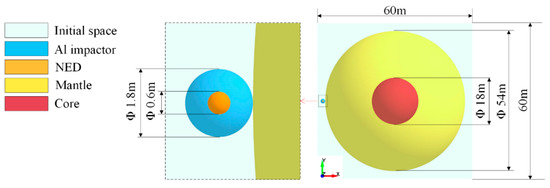
Figure 1.
Calculation model.
The external light-cyan area in the figure represents the initial space. The spherical asteroid is 54 m in diameter, with an 18 m diameter core (red). The core is composed of granite with a density of 2630 kg/m3. The yellow part outside the core is the mantle, composed of low-strength rubble piles with a density of 1910 kg/m3. The asteroid’s total mass is approximately 1.597 × 10⁸ kg, and its bulk density is 1937 kg/m3. The blue sphere on the left is a kinetic impactor made of aluminum alloy, and its interior orange spherical part is the NED. In [33], the outer diameter of the aluminum sphere was 1.8 m and the inner diameter was 0.6 m. The mass of the impactor was 8145 kg, and the mass of the NED was 184 kg. The kinetic penetrator hits the asteroid vertically at a velocity of 6.1 km/s; the NED is initiated when the impact shockwave reaches its boundary. The explosion releases an energy equivalent of 60 kt trinitrotoluene (TNT). In this calculation model, the initial space is divided into 4,873,500 hexahedral elements, with a minimum side length of approximately 0.2 m. The impactor is divided into 864 hexahedral elements, with a minimum side length of approximately 0.06 m. The asteroid is divided into 2,331,668 hexahedral elements, with a minimum side length of approximately 0.06 m.
This scenario uses an impactor to create a shallow crater on the surface of the asteroid, in which the NED initiates a subsurface explosion. The deflection momentum gained by the asteroid originates from two parts: the kinetic impactor affects the asteroid by direct momentum transfer, and the nuclear explosion products push the asteroid by transferring momentum. The mass of the impactor is much larger than that of the NED, which poses a significant challenge to the rocket payload. The design of the deflection scheme should balance the relationship between the mass of the impactor, explosion equivalent, and velocity change of the asteroid. Therefore, it is necessary to quantitatively analyze the contribution of the kinetic impact and nuclear explosion to the velocity change of the asteroid.
As a comparative analysis, we divided the process of the penetrating explosion into two parts: kinetic impact and explosion in the impact crater. By calculating the deflection effects of the three working conditions, we can compare the respective deflection effects of the kinetic impact and the nuclear explosion and determine the contribution of the kinetic impact and the nuclear explosion to the deflection effect in the penetrating explosion scheme. The specific numerical simulation conditions are listed in Table 2.

Table 2.
Numerical simulation conditions.
2.3. Parameters of Simulation
All keywords are edited by LS-PrePost, which is the pre-processing software of LS-DYNA. The impactor and asteroid are divided into hexahedral Lagrangian elements for the adaptive method. The keyword CONTACT_AUTOMATIC_SURFACE_TO_SURFACE was used to define the contact between each other, and the keyword CONTACT_INTERIOR was used to define the contact between elements inside one entity. The mantle and core were linked by sharing common node IDs at the interface. The high impact velocity and the vast difference in material strength between the impactor and asteroid increase the mutual penetration between elements. Therefore, the keyword CONTROL_CONTACT was used to define contact stiffness. The parameter SLSFAC controls the contact interface stiffness scale factor. The default value will lead to penetration between elements, while setting SLSFAC = 1.5 can significantly avoid the anomaly.
The NED and the initial space were divided into hexahedral ALE elements. In the keyword SECTION_SOLID, the parameter ELFORM should be set to 12, which indicates that one-point integration with a single material and void is adapted. NED was filled in the initial space using the keyword INITIAL_VOLUME_FRACTION_GEOMETRY. The parameter AMMGID was set to 1, indicating NED, and AMMGID was set to 2, indicating the initial space. The keyword INITIAL_VELOCITY_GENERATION is used to define the velocity of the NED, and the keyword ALE_REFERENCE_SYSTEM_GROUP is used to define the reference coordinate system.
The parameter ITHK in the keyword CONTROL_SPH was set to 1, indicating that the volume of each particle was considered in the contact process. The parameter NQ in the keyword DEFINE_ADAPTIVE_SOLID_TO_SPH was set to 1, which means that one solid element was adapted to one SPH element. The ICPL was set to 1 to enable a coupling algorithm between the particles and elements. IOPT was set to 1, indicating that coupling began when the corresponding elements failed. In the keyword HOURGLASS, corresponding to SPH, the parameters QM, Q1, and Q2 were set to 1 to avoid penetration between particles. In the keyword HOURGLASS, corresponding to ALE, the parameter QM should be set to 1 × 10⁻⁶ to improve the calculation speed and stability.
2.4. Material Model
According to point explosion theory [43], the shock wave generated by an explosion is only related to the total energy of the explosion, and a nuclear explosion is equivalent to an explosion of conventional explosives with high energy density. This study simplifies the near-field physical process of nuclear explosions and simulates a nuclear explosion by increasing the energy density per unit volume of TNT. The explosion process was simulated using the Jones–Wilkins–Lee (JWL) equation of state (EOS) [56], expressed as
where P is the pressure of the explosive product; A and B are the pressure coefficients; R1 and R2 are the principal and secondary Eigenvalues to depict the short-range and long-range behavior of the explosive products, respectively; ω is the fractional part of the energy (E0) contributing to the pressure; and E0 and V are the internal energy per initial volume and relative volume, respectively. The NED parameters are listed in Table 3.
where E is the total energy released by the explosion and V1 is the volume of the NED.

Table 3.
JWL parameters of the NED.
The Holmquist–Johnson–Cook (HJC) model was selected to model the material behavior of the asteroid [57,58]; the material parameters are listed in Table 4. The HJC model comprehensively considers the effects of compaction and crushing, strain rate, damage evolution, and confining pressure. It can describe the deformation and fracture characteristics of rocks, concrete, and other brittle materials under enormous strain, high strain rate, and high hydrostatic pressure [59]. It is widely used in the numerical simulation of the damaging effects of rock materials under the action of explosions and impact loads [60].

Table 4.
Parameters of asteroid.
The HJC model uses the accumulation of the equivalent plastic strain and plastic volumetric strain to describe the material damage, which is expressed as
where Δ𝜀𝑝 and Δ𝜇𝑝 are the equivalent plastic strain and plastic volumetric strain, is the total plastic strain under constant pressure until fracture, D1 and D2 are damage constants, is the normalized pressure, P is the actual pressure; is the normalized maximum hydrostatic tensile, T is the maximum hydrostatic tensile and EFmin is the amount of plastic strain before fracture.
The EOS model of HJC consists of three stages. The first stage (P < Pcrush) is the elastic stage, the second stage (Pcrush < P < Plock) is the plastic stage, which is characterized by the gradual compression of the initial holes in the material to produce plastic deformation, and the third stage (P > Plock) is the compaction stage, which is expressed as
where is the modified volumetric strain; Pcrush and Plock are the crushing pressure and locking pressure, respectively; μcrush and μlock are the crushing volumetric strain and locking volumetric strain, and K1, K2 and K3 are material constants. Using the meso-porosity model, we can study the effect of the internal porosity of the rubble pile on shock wave propagation and asteroid structural response. However, the meso-porosity model is not used in this paper, and we only use the homogeneous model to approximate the rubble pile structure. With the rubble pile material parameters applied, the structural response of the rubble pile asteroid under explosion loading can still be approximated.
The keyword MAT_ADD_EROSION was used to define the material failure criterion. The parameters are listed in Table 5, where Pmax is the maximum hydrostatic pressure; Tmax is the maximum hydrostatic tension; and εmax is the maximum tensile strain, respectively.

Table 5.
Erosion parameters of asteroid.
The Johnson–Cook (JC) strength model and the Gruneisen equation of state were selected to model the material behavior of the impactor. The JC model is widely used to describe materials subjected to a high strain rate, and is expressed as
where A1 is the static yield limit, B1 is the strain hardening modulus, n is the strain hardening exponent, C is the strain rate coefficient, m is the thermal softening exponent, is the equivalent plastic strain, is the dimensionless effective plastic strain rate, and is the dimensionless temperature. We selected the maximum tensile stress criterion and the JC failure model to simulate tensile and compression failure, respectively. The material parameters are listed in Table 6. Based on the experience of He et al. [54,61] an acceptable simulation result was obtained by setting the maximum tensile stress failure criterion to 2.6 GPa

Table 6.
Parameters of kinetic impactor.
3. Material Response of the Asteroid under Penetrating Explosion
The penetration depth of the impactor when the NED is initiated determines its initiation position. To ensure the credibility of the numerical simulation, it is necessary to determine the precise initiation time. Due to the significant difference in volume between the impactor and the asteroid, it is difficult to accurately describe the shock wave propagation and explosion product expansion using the full model. Therefore, in addition to the full structural model, we also build a mesh-refined local model, as shown in Figure 2. This model is a hexahedron of 12 m × 12 m × 7 m, and the red edge is the non-reflection boundary. In this model, the initial space is divided into 3,710,000 hexahedral elements, with a minimum side length of approximately 0.05 m. The impactor is divided into 155,520 hexahedral elements, with a minimum side length of approximately 0.01 m. The asteroid is divided into 1,716,104 hexahedral elements, with a minimum side length of approximately 0.04 m.
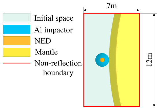
Figure 2.
Mesh-refined local model.
We used the mesh-refined local model to simulate the propagation of the shock wave in the impactor and asteroid during the kinetic impact phase, to determine the initiation time of the NED, and to show the expansion of the explosion products and failure of the impactor after the NED was initiated. Owing to the limited size of the mesh-refined local model, it is impossible to simulate the entire process of expansion and pressure change of the explosion products in space. Therefore, the full model was used later to simulate the expansion of the explosion products and material response of the asteroid under a penetrating explosion. Referring to the shock initiation pressure of the TNT [43], we set the initiation pressure of the NED to 1.4 GPa; that is, the initiation occurs when the surface pressure of the NED reaches 1.4 GPa.
3.1. Crater Formation and Shock Initiation
The hypervelocity impact of the impactor on the asteroid induced high-amplitude shock waves propagating into the Al impactor and asteroid materials. The propagation velocity of the shockwave in the Al impactor is higher than that observed in the asteroid. Figure 3 shows the pressure contours of the Al impactor and asteroid during the kinetic impact process to illustrate the process of shock wave propagation, material failure, and shock initiation of the NED.
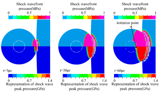
Figure 3.
Propagation of impact-induced shock wave.
The shock wavefront propagates fast, but its pressure is too low to initiate the NED. Only the peak of the shock wave can initiate the NED. Therefore, we use the shock wavefront to represent the shock wave propagation distance, and the shock wave peak to show the shock initiation of the NED. The pressure display range of the upper half is 0~1 MPa, and the areas with pressures higher than 1 MPa are shown in purple, mainly representing the propagation distance of the shock wavefront. As the initiation pressure is 1.4 GPa in this study, the pressure display range of the lower half is 0~1.4 GPa, and the areas with pressures higher than 1.4 GPa are shown in red, mainly representing the propagation distance of the shock wave peak, which is used to determine the initiation time. Evidently, the shock wave peak propagates more slowly than the shock wavefront.
The materials were severely compressed by the intense shock waves produced by the hypervelocity impact. The asteroid starts to fail at t = 5 μs, while the impactor has not yet started to fail. Each failed element was converted into an SPH particle that failed at the moment of activation. The particles represent broken material without tensile and shear stresses that can only withstand compressive stress. Thus, tensile instability was avoided in the SPH. Because the shock wave velocity was greater than the impact velocity of the impactor, the shock wave caused the asteroid elements that had not yet contacted the Al impactor to fail. Before t = 60 μs, the impact shock waves were the only cause of element failure.
The shockwave peak interface in the impactor reached the outer surface of the NED at t = 60 μs, initiating the NED. The impactor penetrated 0.35 m underground at that moment; the center of mass of the NED was 0.54 m above the surface, and the initiation point was 0.24 m above the surface. Therefore, the kinetic impactor could not initiate the NED underground and failed to take advantage of the high-energy coupling of the underground explosion.
After the initiation, the explosion products began to expand, and the impactor elements gradually failed under pressure. The upper part of Figure 4 shows the pressure contours of the explosion products, impactor, and asteroid from t = 70 μs to t = 82 μs, and the lower part shows the velocity of the impactor particles along the impact direction. The maximum value of the pressure range in the figure is not the peak pressure of the explosion products, and the areas with pressures above this value are indicated in purple. The peak pressure of the explosion products occurred in the outer boundary region, and the pressure peak is marked in the upper-right corner of each figure.
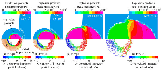
Figure 4.
Pressure change of explosion products and velocity change of impactor particles.
The expansion of the explosion products causes the impactor elements on the impact side to fail almost completely at t = 70 μs. At that point, in time, the velocity of the impactor particles can be divided into four regions. In region 1, the explosion products propelled the particles to a higher velocity than the initial impact velocity of 6.1 km/s. The particles in region 2 had not yet been affected by the explosion products. However, the reaction force of the asteroid slowed the particle velocity in this region below the initial impact velocity. The explosion products decelerated the particles in region 3, giving them a velocity opposite to the impact direction. The particles in region 4, maintaining their initial velocity and moving in the impact direction, had not been affected by the explosion products or the impact shock wave.
The explosion product broke through the impactor at t = 74 μs. The impact shock wavefront propagated about 0.02 m from t = 70 μs to t = 74 μs, and the average wave velocity was about 5 km/s. The explosion products propagated about 0.64 m from t = 70 μs to t = 74 μs, and the average wave velocity was about 160 km/s. The explosion products exceeded the impact shock wavefront at t = 74 μs, and they caused damage to the asteroid together with impactor particles in region 1.
At t = 78 μs, the velocities of all particles in regions 1 and 2 were higher than the initial velocity because of the propelling effect of the explosion products. Momentum was transferred to the asteroid by the particles and explosion products moving in the same direction. All the particles in regions 3 and 4 gained a velocity opposite to the impact direction, and these particles would fly away from the asteroid instead of hitting it. The momentum they carried would not be transferred to the asteroid. This part of the impactor obtained momentum opposite to the impact direction under the push of the explosion products, which did not violate momentum conservation. The explosion products pushed the asteroid at the same time, causing the asteroid to gain momentum along the impact direction. The momentum change of the explosion products to the impactor and the asteroid was equal in magnitude and opposite in direction, and the system always satisfied the momentum conservation. The statistics of all the particles show that the total mass of the particles with a velocity consistent with the impact direction at this moment was 3967 kg, while the mass of the impactor was 8145 kg, which implies that more than half of the initial momentum of the impactor was wasted.
The impactor elements completely failed at t = 82 μs, and the explosion products began to expand into the surrounding space. The penetration depth of the impactor was approximately 0.46 m. The explosion products expanded in space, and the pressure decreased rapidly. In the following subsection, we use the full model to describe the expansion and pressure drop process of explosion products.
3.2. Pressure Attenuation of Explosion Products and Explosion Energy Loading
After t = 82 μs, as the explosion products expand further in space, the entire process of asteroid damage cannot be simulated using the mesh-refined local model because of the limited volume. Therefore, a full model is required to simulate the entire process of expansion and pressure change of explosion products in space.
We first compared the simulation results of the mesh-refined local model and the full model at t = 82 μs to verify the reliability of the calculation. Figure 5 shows the process of expansion and pressure change of the explosion products in space, illustrating the loading mode of the explosion energy.
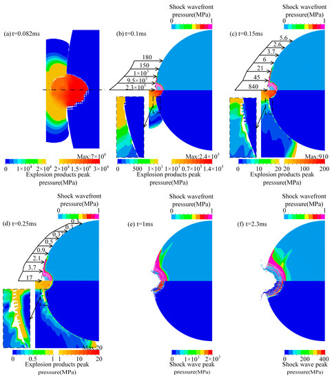
Figure 5.
Attenuation of explosion products pressure and damage to the asteroid’s surface. (a) comparison of the simulation results of the mesh-refined local model (upper part) and the full model (lower part) at t = 0.082 ms; (b) pressure distribution of the explosion products on the surface of the asteroid and crater at t = 0.1 ms; (c) pressure distribution of the explosion products on the surface of the asteroid and crater at t = 0.15 ms; (d) pressure distribution of the explosion products on the surface of the asteroid and crater at t = 0.25 ms; (e) the pressure distribution in the impact crater and the wavefront at t = 1 ms; (f) the pressure distribution in the impact crater and the wavefront at t = 2.3 ms.
Figure 5a–d shows the pressure distribution, at two different pressure ranges, of the explosion products on the surface of the asteroid and crater, respectively. The maximum pressure value of the low threshold legend equals the minimum pressure value of the high threshold legend. The pressure of the explosion products in the crater was much greater than that on the surface of the asteroid and decreased rapidly with time. The maximum value of the pressure range in the lower right is not the peak pressure of the explosion products in the crater at that moment; the areas with pressures above this value are shown in red. The peak pressure of the explosion products, which is marked above the legend, occurred in the outer boundary region.
In particular, Figure 5a compares the simulation results of the mesh-refined local model and full model at t = 82 μs. The upper and lower parts show the simulation results of the local and full models, respectively, and use the same scale. The different pressure ranges represent the pressure distribution of the explosion products on the surface of the asteroid and crater. The pressure and propagation distance of the explosion products simulated by the two models were relatively close; therefore, the simulation results of the full model were highly reliable.
The pressure of the explosion products remained high after they broke through the impactor. The explosion products and impactor particles along the impact direction continued to affect the crater, resulting in the failure of the asteroid elements in the crater and expansion of the crater size. The explosion products expand freely in space, exerting pressure on the surface of the asteroid and causing compression failure of the elements. The maximum pressure of the explosion products on the asteroid’s surface is 20 GPa at t = 82 μs.
The upper part of Figure 5b–f has a pressure range of 0–1 MPa, showing a shock wavefront that propagates inward along the surface of the asteroid and the inner surface of the crater. The upper part of Figure 5b–d shows the pressure distribution curves of the explosion products in the crater and on the surface of the asteroid at the corresponding time. The position of the arrow is the projection of the boundary of the explosion products onto the initial outline of the asteroid, and the length of the arrow represents the logarithm of the pressure at that location (MPa).
The lower part of Figure 5b–d shows the pressure attenuation of the explosion products and the damage process of the asteroid. Different pressure ranges were used to represent the pressure distributions of the explosion products in the crater and on the surface of the asteroid. As the propagation distance increases, the pressure of the explosion products decreases rapidly. The elements on the surface of the asteroid began to fail at t = 0.1 ms due to the pressure exerted by the explosion products, and the failure area expanded subsequently. From t = 0.1 ms to t = 0.25 ms, the pressure of the explosion products on the asteroid’s surface decreased from 2 GPa to 1 MPa. The expansion of the explosion products had acted on nearly half of the asteroid’s surface at t = 0.25 ms, and the failure area expanded further. At this point, the peak pressure of the explosion products in the crater was reduced to 20 MPa.
After t = 0.25 ms, the kinetic energy of the failed elements was transferred to the asteroid through the inward extrusion of the particles because the particles in the crater inherited the velocity and mass of the corresponding elements. The inward extrusion of the particles created compression waves that propagated into the asteroid, causing elements to fail and expanding the crater. The explosion products were hidden in Figure 5e,f because the pressure did not significantly affect the surface of the asteroid. Figure 5e,f shows the inward extrusion of particles in the crater to transfer energy. Different pressure thresholds represent the pressure distribution in the impact crater and the position of the compression wavefront. Figure 5e,f shows that the elements near the asteroid crater were gradually compressed and failed during the energy-transfer process. The crater size increased, and the compression wave gradually propagated into the asteroid.
Removing the failed elements during the FEM calculation results in significant system momentum and energy loss because the failed elements still have high velocities. Therefore, we used the FE-SPH adaptive method to transform the failed elements into SPH particles during asteroid fragmentation simulations. The particles inherit the velocity and mass of the corresponding elements and transfer energy to the asteroid by squeezing into the crater, thereby avoiding the loss of system energy.
The actual situation can be investigated using the single-material ALE method to simulate the explosion process. The explosion products can expand freely in space, maintain a smooth material interface, and exert pressure on the surface of the asteroid. This pressure is sufficient to cause significant damage to low-intensity asteroids. The SPH method uses a limited number of particles to simulate the expansion of explosion products; therefore, the boundary of the explosion products is blurred. Combining the single-material ALE and FE-SPH methods can demonstrate the process of explosion energy loading and asteroid damage.
4. Structural Response of the Asteroid under Penetrating Explosion
This section details the velocity change of hazardous asteroids and analyzes the degree of damage and risk from fragmentation. The uncertainty of the deflection effect is primarily due to the diversity of asteroid material composition [62]. Rubble pile asteroids are easily broken into large pieces owing to their low strength, so it is particularly important to analyze the risk of fragmentation. In this study, the explosion greatly damaged the asteroid. This was because the low strength of the mantle material caused the flyoff of dangerous fragments. This section describes the process used by the full model to analyze the structural response of an asteroid to the penetrating explosion condition. We describe the dynamic damage of the asteroid and the particle scattering and extrusion process and explain the phenomenon of particle rebound in the crater and the generation of large, dangerous blocks.
The damage mode of the asteroid is analyzed in detail in Figure 6. Figure 6 shows the damage evolution and pressure propagation of the asteroid under a penetrating explosion, in which the upper part is the damage contour and the lower half is the pressure contour. We defined the impact side as the head of the asteroid and the other side as the rear. There was a large accumulation of particles inside the crater, and their thickness gradually increased with time, reaching approximately 10 m at t = 100 ms. The failure/non-failure boundary of the elements in the crater defined the actual crater surface and represented the true damage range of the asteroid. All non-failed asteroid elements that remained bound together were regarded as the asteroid body.
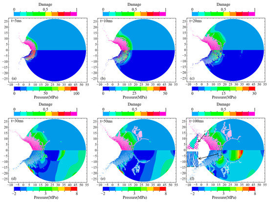
Figure 6.
Damage evolution and pressure propagation of the asteroid under penetrating explosion: the upper half is the damage contour, and the lower half is the pressure contour. (a) the damage contour (upper part) and the pressure contour (lower half) of the asteroid at t = 5 ms; (b) the damage contour (upper part) and the pressure contour (lower half) of the asteroid at t = 10 ms; (c) the damage contour (upper part) and the pressure contour (lower half) of the asteroid at t = 20 ms; (d) the damage contour (upper part) and the pressure contour (lower half) of the asteroid at t = 30ms; (e) the damage contour (upper part) and the pressure contour (lower half) of the asteroid at t = 50 ms; (f) the damage contour (upper part) and the pressure contour (lower half) of the asteroid at t = 100 ms.
From t = 5 ms to t = 10 ms, the particles in the crater still had high pressure and were driven around by kinetic energy, resulting in the continuous expansion of the crater size. At t = 20 ms, cracks formed by tensile failure occurred around the crater, and blocks composed of non-failed elements appeared at the bottom of the crater. The inward extrusion of the crater floor resulted in the compressive failure of the elements at the head interface of the mantle/core, and the particle pressure dropped to a lower level. Owing to its high strength, the core was undamaged, and cracks propagated along the mantle/core interface.
During the inward extrusion, the particle velocity in the crater gradually decreases. After interacting with the non-failed mantle and core elements, the particles bounced out of the crater after their relative velocity dropped to zero. The gravitational pull of the asteroid slows down the bouncing particles. However, the gravitational pull of the asteroid was small and had a limited influence on the particle velocity. The escape velocity from the surface is given by [21]:
where M = 1.597 × 10⁸ kg is the mass of the asteroid, G = 6.67 × 10⁻¹¹ Nm2/kg2 is the universal gravitational constant, and R = 27 m is the asteroid’s radius. The calculation shows that the escape velocity from the asteroid’s surface is only 2.8 cm/s; therefore, some particles may fly away because the rebound velocity exceeds the escape velocity.
The maximum pressure around the crater is attenuated to 8 MPa at t = 30 ms. The particles in the crater squeezed along the radial direction of the crater, causing a slight deformation of the mantle, and a negative pressure area began to appear on the mantle. Tensile failure cracks began to occur in the negative pressure region, and the number of cracks around the crater and inside the mantle increased and continued to expand. Simultaneously, the particles in the crater began to bounce outward. Some of them gradually escaped from the asteroid body and flew free. In contrast, the others regained velocity in the direction of the asteroid’s motion by interacting with the elements at the edge of the crater, eventually moving with the asteroid body.
Many cracks formed in the mantle at t = 50 ms but did not extend to the surface of the asteroid. Particle rebound causes gaps between the particles at the bottom of the crater. From t = 50 ms to t = 100 ms, the damage degree of the elements around the crater no longer increased, but the particles in the crater continued to squeeze the elements around the crater as they bounced outward, causing cracks around the crater to expand, as shown in Figure 6f. The squeezing of the particles caused the large blocks around the crater to break away from the asteroid body at t = 100 ms, and the rebound of the particles caused the gaps between the particles to widen at the bottom of the crater. Comparing Figure 6d–f, the rebound of the particles led to a significantly smaller apparent crater depth.
The damage morphology of the asteroid is described in Figure 7. The crack pattern and fragment distribution at t = 100 ms are shown, with the volume and mass of typical bulks marked (Figure 7). The upper part of the figure shows the particle distribution characteristics, while the lower part hides the particles, focusing on the flying elements and large blocks. There are large blocks around the crater, and we selected two of them for magnification and display to characterize the shape, volume, and mass of such large blocks. The penetrating explosion caused significant damage to the mantle, but the core was undamaged. There were many cracks in the mantle, but only a few cracks were observed on the outer surface of the asteroid, indicating that most cracks in the mantle did not extend to the surface. The cracks on the surface of the asteroid were not interconnected; therefore, this condition did not cause the mantle to break up. However, numerous cracks in the mantle caused the asteroid’s overall strength to be significantly reduced. At the head of the asteroid, almost all mantle elements failed. The core was covered with a layer of rubble with no strength, which undoubtedly increased the risk of core–mantle separation.
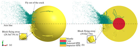
Figure 7.
Asteroid damage and fragments morphology induced by penetrating explosion (t = 100 ms): (a) main view, (b) cross-sectional view.
The explosion caused numerous fragments to fly outward, including most of the SPH particles and some non-failed elements. Large blocks composed of non-failed elements around the crater broke away from the asteroid body. Normally, large blocks pose a threat to Earth [63], which increases the uncertainty of the deflection effect. Therefore, it is necessary to evaluate the risk of asteroid fragmentation caused by the explosion. The FE-SPH adaptive method can be used to obtain the geometric characteristics and development process of cracks, which is convenient for evaluating the risk of asteroid fragmentation and for obtaining the shape and volume of dangerous fragments.
It is worth noting that, in the case of a penetrating explosion, before the NED initiates, some asteroid elements are converted into SPH particles owing to compression failure. Explosion products cannot act on these particles because ALE materials cannot be coupled with the SPH particles. From the overall perspective of the deflection process, the unabsorbed energy of these particles will be coupled to the elements in the crater; therefore, the unabsorbed explosion energy of these particles has a limited impact on the overall deflection effect. In Section 6, we discuss the contribution of kinetic impact and nuclear explosion on the deflection effect to determine the degree of influence of these particles not coupled with the explosion products on the deflection effect.
5. Validation of Numerical Simulation Methods
The above simulation results show that the combination of the single-material ALE method and the FE-SPH adaptive method can better demonstrate the asteroid damage process and fragment distributions than the FEM or SPH method alone. We compared the numerical simulation results of this study with the results from [33] Figure 8 shows the asteroid density contour at the corresponding time, where the upper and lower parts correspond to the numerical results of this study and [33], respectively. NED initiated at t = 1 ms in [33] and the result was reported at t = 2.3 ms, with an explosion shock wave propagation time of 1.3 ms. The initiation time of NED in this study was t = 0.06 ms. Therefore, the numerical simulation results at the same shock wave propagation time (t = 1.36 ms) and the same end time (t = 2.3 ms) were compared simultaneously. In the figure, the lower density limit is the density of mantle rubble, and the upper limit is the density of core granite.
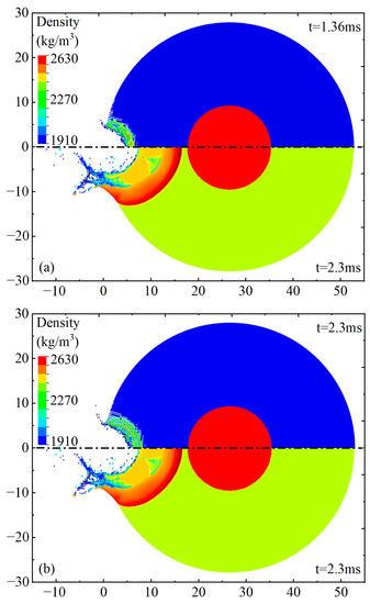
Figure 8.
Comparison of density contour with Kaplinger et al. (a) comparison of density contour at t = 1.36 ms; (b) comparison of density contour at t = 2.3 ms. [33].
According to 57, the sound velocity of common rubble is . In the simulation results of [33], the shock wave propagated about 15 m from t = 1.0 ms to t = 2.3 ms. The average shock wave velocity was about 11.5 km/s, which in reality is much higher than the maximum possible value of the rubble material. On the contrary, it is evident from Figure 5b–f that in the simulation results of this study, the shock wave propagates about 1.2 m from t = 0.1 ms to t = 0.25 ms, and the average wave velocity is about 8 km/s. The shock wave propagates about 6 m from t = 0.25 ms to t = 2.3 ms, and the average wave velocity is about 2.9 km/s, which is closer to the realistic situation; therefore, the simulation results in this study have higher reliability.
The present simulations clearly show the damage boundary of the asteroid body (actual crater), edge of the failed rock (apparent crater), and scattering of fragments. The laws of crater expansion and fragment scattering obtained in this study are consistent with those in [33]. The initiation time of the NED in this study was different from that of [33]. The shockwave propagation distance and crater size obtained in this study and in [33] were different. The major reasons for these differences are as follows. First, the NED initiated at t = 1 ms in [33], which is quite different from the time required by the shock wave to propagate to the surface of the NED in the actual situation. In this study, the initiation time obtained by simulating the shock wave propagation in the impactor was more accurate. Second, the NED in this study was initiated above the mantle surface. Compared with the subsurface explosion in [33], the explosion energy coupling was relatively lower, so the crater size was smaller and the fragment velocity was lower.
Although there are some differences in the simulation results, those in this study have high credibility. The advantages of using the single-material ALE method and the FE-SPH adaptive method to simulate the explosion deflection of asteroids are as follows. First, the interface of the explosion products is smooth, and the expansion process and pressure change of the explosion products can be observed visually. Second, the single-material ALE method has better convergence and high computational efficiency for simulating nuclear explosions. Finally, the damage evolution of the asteroid and the accumulation and scattering of fragments can be used to fully evaluate the damage effect.
6. Structural Response Simulation for Solitary Cases
The contribution of kinetic impact and nuclear explosion to the asteroid deflection effect in the penetrating explosion condition was quantitatively analyzed. We independently modeled the impact and explosion, simulating the asteroid deflection using kinetic impact and static explosion in the impact crater, respectively.
6.1. Damage Process of the Asteroid under Kinetic Impact
As mentioned above, the impactor was used to impact the asteroid at the same velocity, without the NED affecting the impact process. A kinetic impact, to deflect the asteroid, transfers momentum to the asteroid using two components: the momentum that is directly imparted from the impactor and an additional momentum transferred to the asteroid by the thrust in the opposite direction of the crater ejecta [51,52,64,65]. The law of conservation of momentum can be used to calculate the momentum transferred by the impactor to the asteroid. The uncertainty is primarily affected by the reverse thrust of the ejecta on the asteroid. The law of conservation of momentum is:
where mp and vp are the mass and velocity of the impactor, respectively. Pej is the component of the escaping ejecta momentum along the direction of the impact trajectory. β is the momentum multiplication factor, which depends strongly on the porosity, strength, friction, and layering of the asteroid (not discussed in this study). ma and va are the mass and velocity of the asteroid body, respectively.
Figure 9 shows the damage evolution and pressure propagation of the asteroid under the sole kinetic impact condition. The upper half is the damage contour, and the lower half is the pressure contour. Unlike in Section 3, the impactor collided with the asteroid and came to a stop (t = 15 ms). After which the asteroid continued to undergo structural response and local failure. After the impact, a crater was formed, and the shock wave propagated through the asteroid. The impactor elements failed completely at t = 1 ms, and the penetration depth of the impactor was approximately 2.4 m. At this point, the impactor particles still had a high velocity. They continued to compress the asteroid particles and elements in the crater, further expanding its size. The non-failed elements around the crater suffered damage.
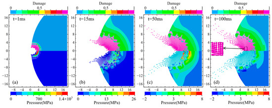
Figure 9.
Damage evolution and pressure propagation of the asteroid under kinetic impact: the upper half is the damage contour, and the lower half is the pressure contour.(a) the damage contour (upper part) and the pressure contour (lower half) of the asteroid at t = 1 ms; (b) the damage contour (upper part) and the pressure contour (lower half) of the asteroid at t = 15 ms; (c) the damage contour (upper part) and the pressure contour (lower half) of the asteroid at t = 50 ms; (d) the damage contour (upper part) and the pressure contour (lower half) of the asteroid at t = 100 ms.
The particles in the crater began to bounce outward at t = 15 ms, and the penetration depth of the impactor reached the maximum depth of 4.4 m at this time. Subsequently, the cracks around the crater no longer propagated owing to the attenuation of the shock wave pressure. Comparing Figure 9b–d, the apparent crater depth was significantly reduced owing to the rebound of the particles from t = 15 ms to t = 100 ms.
Figure 10 shows the damage morphology of the asteroid as a whole at t = 100 ms and marks the volume and mass of typical large blocks. The upper part of the figure shows the particle distribution characteristics, while the lower part hides the particles, focusing on the flying elements and large blocks. The kinetic impact only caused limited damage to the asteroid, with numerous tiny cracks distributed around the crater and no apparent cracks in the mantle. The number of fragments was relatively small; however, some large blocks composed of non-failed elements moved away from the asteroid body.

Figure 10.
Asteroid damage and fragments morphology induced by kinetic impact (t = 100 ms): (a) main view, (b) cross-sectional view.
6.2. Damage Process of the Asteroid under the Static Explosion in the Impact Crater
In this scenario, the NED wrapped with the impactor was stationary and initiated in the impact crater at t = 60 μs extracted in Section 3.1 (0.35 m underground). Figure 11 shows the damage evolution and pressure propagation of the asteroid, where the upper half is the damage contour and the lower half is the pressure contour. Compared with Figure 6, the static explosion in the impact crater caused minor damage to the asteroid than the penetrating explosion. The extrusion of the particles still caused the larger blocks around the crater to break away from the asteroid body at t = 100 ms, and the rebound of the particles caused obvious cracks between the particles on the crater floor.
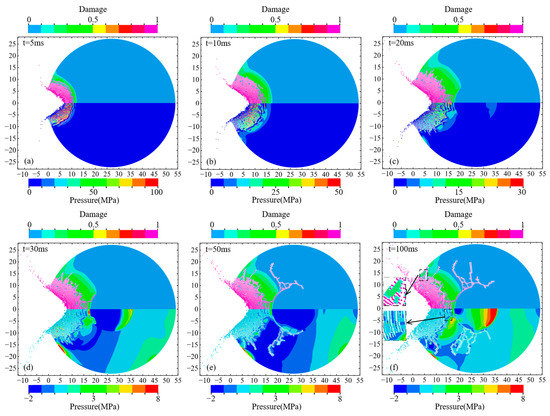
Figure 11.
Damage evolution and pressure propagation of the asteroid under the static explosion in the impact crater: the upper half is the damage contour, and the lower half is the pressure contour. (a) the damage contour (upper part) and the pressure contour (lower half) of the asteroid at t = 5 ms; (b) the damage contour (upper part) and the pressure contour (lower half) of the asteroid at t = 10 ms; (c) the damage contour (upper part) and the pressure contour (lower half) of the asteroid at t = 20 ms; (d) the damage contour (upper part) and the pressure contour (lower half) of the asteroid at t = 30 ms; (e) the damage contour (upper part) and the pressure contour (lower half) of the asteroid at t = 50 ms; (f) the damage contour (upper part) and the pressure contour (lower half) of the asteroid at t = 100 ms.
Figure 12 shows the crack pattern and the distribution of the fragments at t = 100 ms and marks the volume and mass of typical large blocks. The upper part of the figure shows the particle distribution characteristics, while the lower part hides the particles, focusing on the flying elements and large blocks. The static explosion in the impact crater caused slightly less damage to the asteroid than the penetrating explosion did. There were many cracks in the mantle, many fragments flowed outward, and some large blocks separated from the asteroid body. Although the explosion did not break the asteroid, numerous cracks significantly reduced its overall strength.
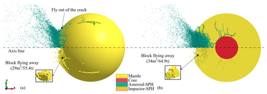
Figure 12.
Asteroid damage and fragments morphology induced by the static explosion in the impact crater (t = 100 ms): (a) main view, (b) cross-sectional view.
7. Comparison of the Deflection Effects of the Three Conditions
Figure 13 shows the variation in asteroid velocity with time under the three aforementioned conditions. This velocity is the weighted average of all element velocities of the asteroid body. The velocity change of the asteroid is 1.9 m/s under static explosion in the impact crater, which is 0.49 m/s under kinetic impact. The velocity change is 2.18 m/s under penetrating explosion, higher than that of the static explosion in the impact crater due to the contribution of the momentum transfer of the impactor. However, this velocity change is less than the sum of the velocity changes of the asteroid under the above two conditions, because the momentum of the impactor is not entirely transferred to the asteroid.
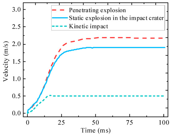
Figure 13.
Velocity–time curves of the asteroid under different deflection conditions.
The results in Section 3.1 show that approximately 48.7% of the impactor momentum can be transferred to the asteroid, giving the asteroid a velocity change of approximately 0.24 m/s. Adding the velocity change of 1.9 m/s from the static explosion in the impact crater, the velocity change of the asteroid with a penetrating explosion is 2.14 m/s, which is marginally (2%) different from the numerical simulation results of this study. Therefore, accurate calculation results can be obtained by decoupling the penetrating explosion condition into two processes: kinetic impact and static explosion at the impact crater. In addition, the simulation result was less affected by the uncoupling of the explosion products with particles generated before NED initiation.
In the case of penetrating explosions, the contribution ratios of kinetic impact and nuclear explosion to the asteroid velocity change were 11% and 89%, respectively. Despite the high mass of the kinetic impactor used in this study, the change in velocity of the asteroid was primarily caused by the nuclear explosion. The mass of the kinetic impactor in the HAIV design is typically more than ten times smaller, contributing less to the asteroid’s velocity change.
Taking the asteroid body as a reference, fragments with a negative velocity will fly away from the asteroid body. The fragments in the inner cracks continuously collided with the surrounding elements, and the velocity stabilized after slight oscillations and moved with the asteroid body. By counting the mass and velocity information of all particles and elements, the velocity distribution of the fragments flying away from the asteroid at t = 100 ms under different conditions is shown in Figure 14, where the ordinate is the total mass of the fragments in each velocity interval. A velocity range of 0–50 m/s with significant differences in the velocity distribution was selected as the research object.
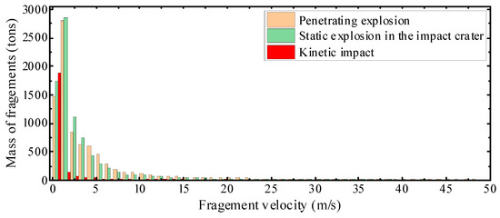
Figure 14.
Velocity distribution of the fragments under different deflection conditions.
Under kinetic impact, the fragments have a lower total mass and lower velocity. The fragment velocity is concentrated in the range of 1–6 m/s, and the total mass is approximately 2.66 × 10⁶ kg, accounting for 1.7% of the asteroid’s mass. The velocity distribution of the fragments under a static explosion in the impact crater was similar to that of a penetrating explosion. The fragment velocity was primarily concentrated in 1–20 m/s. The total mass of the fragments is approximately 9.38 × 10⁶ kg under static explosion in the impact crater, accounting for 5.9% of the mass of the asteroid. This value is approximately 9.66 × 10⁶ kg under a penetrating explosion, accounting for 6% of the mass of the asteroid. Most of the fragments with velocities below 3 m/s bounced off the crater. These fragments have the highest share of the total mass of the fragments, whereas the fragments generated during the material response stage have a higher velocity but lower mass share.
The formation mechanisms of the craters on asteroids are significantly different from those on Earth. Asteroids are small, with a low surface escape velocity and low gravitational acceleration. Therefore, most ejecta reaches escape velocity and fly away from the asteroid without falling back to the crater [66]. Only a few fragments in the crater do not fly away and move with the asteroid body. These fragments are extremely low in strength, cannot withstand tensile stress, and can easily fly away with a slight disturbance.
Figure 15 shows the mass percentage of the asteroid body, flying fragments, flying blocks, and fragments moving with the asteroid to the total mass. The asteroid suffered the most damage under the penetrating explosion, resulting in the most fragments; 85.6% of the asteroid’s mass remained bound together. The flying fragments accounted for 6.1% of the asteroid’s mass, the fragments moving with the body accounted for 7.6% of the asteroid’s mass, and the large blocks flying away accounted for 0.7% of the asteroid’s mass. The kinetic impact causes minimal damage to the asteroid; 97.6% of the asteroid’s mass remains bound together. The flying fragments account for 1.7% of the mass of the asteroid, the fragments moving with the body account for 0.5% of the mass of the asteroid, and the large blocks flying away account for 0.2% of the mass of the asteroid.
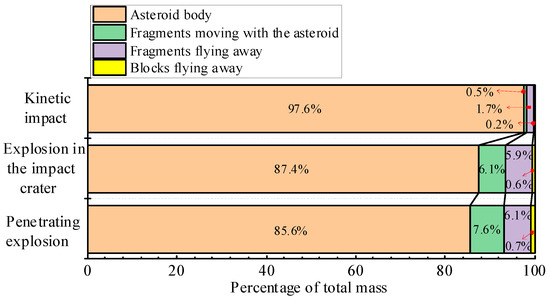
Figure 15.
The mass percentage of each part of the asteroid under different conditions. The red arrows indicate the mass percentage of the parts corresponding to the tail of the arrow.
The final deflection effect is greatly affected by the physical and compositional properties of the asteroid, such as its geometry, density, material strength, and porosity [67,68]. Deflection methodologies should first ensure that the asteroid obtains the desired change in velocity. The above analysis shows that the nuclear explosion method obtains a higher velocity change than the kinetic impact method. However, damage to the asteroid was greater, resulting in more dangerous fragments. A velocity change of 1.45 cm/s is sufficient to eliminate the impact risk when the warning time is ten years [28]. This velocity can be achieved for smaller asteroids by kinetic impact or a small-yield nuclear explosion. A nuclear explosion is the only viable deflection option when the warning time is short or the asteroid is large. When the warning time is too short to deflect the asteroid, the nuclear option can completely shatter the asteroid to eliminate risk.
8. Discussion and Conclusions
Asteroids exist in absolute vacuum, which significantly affects the effects of explosion damage. Using the single-material ALE method, we can observe the expansion boundary and pressure change process of explosion products in absolute vacuum. The numerical results confirm that combining the single-material ALE method and the FE-SPH adaptive method is ideal for simulating explosion-deflection processes. Combined with the meso-modeling approach, this method can be further used to study the explosion deflection of hazardous asteroids with complex geometries and material compositions. In kinetic impact-deflecting asteroid studies, the FE-SPH method can be used to fully explore the influence of parameters such as porosity, strength, friction, and layering of the asteroid on the amount of momentum enhancement (momentum multiplication factor β) caused by the ejecta.
The use of the FE-SPH adaptive method avoids the loss of system energy by transforming failed elements into SPH particles during the simulation. Using this method, we obtained the actual crater shape, crack propagation, and fragment distribution. The velocity distribution of the fragments can be quickly obtained using statistical SPH particle and element information. Therefore, this method is more suitable for studying the explosion deflection of hazardous asteroids than the FEM and SPH methods.
The simulation results confirm that the deflection momentum of the asteroid under the penetrating explosion is equal to the sum of the momentum acquired by the kinetic impact and the static explosion in the impact crater. For current rocket payloads, the mass of the impactor is typically less than 1/10 of that in this study [15,16], so the contribution of the impactor and the explosion to the asteroid deflection momentum is very disparate. In this study, the penetrating explosion process has been decoupled into kinetic impact and static explosion, respectively. In penetrating explosion-deflected asteroid research, the local model can be used to simulate the impact crater depth and the initiation position of the NED. The penetrating explosion process is then simplified as a static underground explosion at the initiation position, and the full model is used for calculation.
For km-sized asteroids, most fragments undergo gravitational re-accretion [35,69]. Referring to the small asteroid size of <100 m, gravitation has a limited effect on fragment velocity, and most fragments reach escape velocity and fly away from the asteroid body. The temperature and phase change of the material can be investigated using the FE-SPH adaptive method by adding the relevant parameters to the material model. In addition, further studies will investigate the effect of explosion location on the deflection effectiveness of irregularly shaped asteroids.
In this study, the single-material ALE method and the FE-SPH adaptive method are combined to simulate the effects of three deflection methods on a 54 m asteroid: penetrating explosion, kinetic impact, and static explosion in the impact crater. The analysis shows that the penetrating explosion scheme in this study does not fully play the role of a kinetic impactor in cratering. The ideal penetration explosion solution uses an impactor to create a deep crater, in which the NED is initiated. This ensures that the momentum of the impactor is fully transferred to the asteroid and takes advantage of the high-energy coupling of subsurface explosions. Second, nuclear explosions provide asteroids with significantly higher velocity changes than those of kinetic impacts. Finally, although the absolute vacuum environment dramatically reduces explosion energy coupling, nuclear explosions still provide considerable velocity changes.
Three important points are discussed in this study. First, the single-material ALE method was used to simulate the explosion in an absolute vacuum, avoiding the non-convergence of the multi-material ALE method used in the explosion in absolute vacuum. Second, the FE-SPH adaptive method was used to reveal the crack initiation and propagation process in the asteroid and the rebound of fragments in the crater. Quantitative information on fragments and large blocks was generated. Finally, the deflection effects of the penetrating explosion, kinetic impact, and static explosion in the impact crater were compared, and their respective contribution rates were observed.
Author Contributions
Conceptualization, X.C. and P.H.; methodology, X.C. and P.H.; software, Q.H., P.H. and H.L.; validation, P.H.; formal analysis, X.C. and P.H.; investigation, Q.H. and H.L.; resources, P.H.; data curation, X.C. and P.H.; writing—original draft preparation, P.H., Q.H. and H.L.; writing—review and editing, X.C. and P.H.; visualization, X.C. and P.H.; supervision, X.C.; project administration, X.C.; funding acquisition, X.C. All authors have read and agreed to the published version of the manuscript.
Funding
This research was funded by [the National Natural Science Foundation of China] grant number [11872118].
Data Availability Statement
The data supporting reported results are included in the article.
Acknowledgments
This work was supported by the National Natural Science Foundation of China (11872118).
Conflicts of Interest
The authors declare no conflict of interest.
References
- Steel, D. Tunguska at 100: The most dramatic cosmic impact in recent history has gathered up almost as many weird explanations as it knocked down trees. Nature 2008, 453, 1157–1160. [Google Scholar] [CrossRef]
- Brown, P.G.; Assink, J.D.; Astiz, L.; Blaauw, R.; Boslough, M.B.; Borovička, J.; Brachet, N.; Brown, D.; Campbell-Brown, M.; Ceranna, L.; et al. A 500-kiloton airburst over Chelyabinsk and an enhanced hazard from small impactors. Nature 2013, 503, 238–241. [Google Scholar] [CrossRef] [PubMed]
- Popova, O.P.; Jenniskens, P.; Emel’yanenko, V.; Kartashova, A.; Biryukov, E.; Khaibrakhmanov, S.; Shuvalov, V.; Rybnov, Y.; Dudorov, A.; Grokhovsky, V.I.; et al. Chelyabinsk Airburst, Damage Assessment, Meteorite Recovery, and Characterization. Science 2013, 342, 1069–1073. [Google Scholar] [CrossRef]
- Gong, S.P.; Li, J.F.; Gao, Y.F. Dynamics and control of a solar collector system for near Earth object deflection. Res. Astron. Astrophys. 2011, 11, 205. [Google Scholar] [CrossRef]
- Kahle, R.; Kührt, E.; Hahn, G.; Knollenberg, J. Physical limits of solar collectors in deflecting Earth-threatening asteroids. Aerosp. Sci. Technol. 2006, 10, 256–263. [Google Scholar] [CrossRef]
- Vasile, M.; Gibbings, A.; Watson, I.; Hopkins, J.M. Improved laser ablation model for asteroid deflection. Acta Astronaut. 2014, 103, 382–394. [Google Scholar] [CrossRef]
- Zhang, Q.; Walsh, K.J.; Melis, C.; Hughes, G.B.; Lubin, P. Orbital simulations for directed energy deflection of near-earth asteroids. Procedia Eng. 2015, 103, 671–678. [Google Scholar] [CrossRef]
- Thiry, N.; Vasile, M. Theoretical peak performance and optical constraints for the deflection of an S-type asteroid with a continuous wave laser. Adv. Space Res. 2017, 59, 1353–1367. [Google Scholar] [CrossRef]
- Bombardelli, C.; Urrutxua, H.; Merino, M.; Pelaez, J.; Ahedo, E. The ion beam shepherd: A new concept for asteroid deflection. Acta Astronaut. 2013, 90, 98–102. [Google Scholar] [CrossRef]
- Lu, E.T.; Love, S.G. Gravitational tractor for towing asteroids. Nature 2005, 438, 177–178. [Google Scholar] [CrossRef]
- Wie, B. Dynamics and control of gravity tractor spacecraft for asteroid deflection. J. Guid. Control. Dyn. 2008, 31, 1413–1423. [Google Scholar] [CrossRef]
- Ummen, N.; Lappas, V. Polyhedron tracking and gravity tractor asteroid deflection. Acta Astronaut. 2014, 104, 106–124. [Google Scholar] [CrossRef]
- Vasile, M.; Colombo, C. Optimal impact strategies for asteroid deflection. J. Guid. Control. Dyn. 2008, 31, 858–872. [Google Scholar] [CrossRef]
- Wang, Y.; Li, M.; Gong, Z.; Wang, J.; Wang, C.; Zhou, B. Assembled kinetic impactor for deflecting asteroids by combining the spacecraft with the launch vehicle upper stage. Icarus 2021, 368, 114596. [Google Scholar] [CrossRef]
- A’Hearn, M.F.; Belton, M.J.S.; Delamere, W.A.; Kissel, J.; Klaasen, K.P.; McFadden, L.A.; Meech, K.J.; Melosh, H.J.; Schultz, P.H.; Sunshine, J.M.; et al. Deep Impact: Excavating comet Tempel 1. Science 2005, 310, 258–264. [Google Scholar] [CrossRef]
- Nakano, R.; Hirabayashi, M.; Agrusa, H.F.; Ferrari, F.; Meyer, A.J.; Michel, P.; Raducan, S.D.; Sánchez, P.; Zhang, Y. NASA’s Double Asteroid Redirection Test (DART): Mutual Orbital Period Change Due to Reshaping in the Near-Earth Binary Asteroid System (65803) Didymos. Planet. Sci. J. 2022, 3, 148. [Google Scholar] [CrossRef]
- Walker, J.D.; Chocron, S. Near-earth object deflection using conventional explosives. Int. J. Impact Eng. 2008, 35, 1473–1477. [Google Scholar] [CrossRef]
- Fortov, V.; Kondaurov, V.; Lomov, I. Investigation of the nuclear explosion effect on asteroids. Int. J. Impact Eng. 1997, 20, 265–269. [Google Scholar] [CrossRef]
- Dearborn, D.S.; Patenaude, S.; Managan, R.A. The Use of Nuclear Explosives to Disrupt or Divert Asteroids; Lawrence Livermore National Lab (LLNL): Livermore, CA, USA, 2007. [Google Scholar]
- Syal, M.B.; Dearborn, D.S.P.; Schultz, P.H. Limits on the use of nuclear explosives for asteroid deflection. Acta Astronaut. 2013, 90, 103–111. [Google Scholar] [CrossRef]
- Kaplinger, B.; Wie, B.; Dearborn, D. Earth-impact modeling and analysis of a near-Earth object fragmented and dispersed by nuclear subsurface explosions. J. Astronaut. Sci. 2012, 59, 101–119. [Google Scholar] [CrossRef]
- Vasile, M.; Thiry, N. Nuclear cycler: An incremental approach to the deflection of asteroids. Adv. Space Res. 2016, 57, 1805–1819. [Google Scholar] [CrossRef]
- Pitz, A.; Kaplinger, B.; Vardaxis, G.; Wie, B. Conceptual design of a hypervelocity asteroid intercept vehicle (HAIV) and its flight validation mission. Acta Astronaut. 2014, 94, 42–56. [Google Scholar] [CrossRef]
- Barbee, B.W.; Wie, B.; Steiner, M.; Getzandanner, K. Conceptual design of a flight validation mission for a Hypervelocity Asteroid Intercept Vehicle. Acta Astronaut. 2015, 106, 139–159. [Google Scholar] [CrossRef]
- Michel, P. Physical properties of Near-Earth Objects that inform mitigation. Acta Astronaut. 2013, 90, 6–13. [Google Scholar] [CrossRef]
- NASA National Aeronautics and Space Administration. Near-Earth Object Survey and Deflection: Analysis of Alternatives; National Aeronautics and Space Administration: Washington, DC, USA, 2007.
- National Research Council. Defending Planet Earth: Near-Earth Object Surveys and Hazard Mitigation Strategies; The National Academies Press: Washington, DC, USA, 2010. [Google Scholar]
- Greenstreet, S.; Lu, E.; Loucks, M.; Carrico, J.; Kichkaylo, T.; Jurić, M. Required deflection impulses as a function of time before impact for Earth-impacting asteroids. Icarus 2020, 347, 113792. [Google Scholar] [CrossRef]
- Sanchez, J.P.; Colombo, C.; Vasile, M.; Radice, G. Multicriteria comparison among several mitigation strategies for dangerous near-earth objects. J. Guid. Control. Dyn. 2009, 32, 121–142. [Google Scholar] [CrossRef]
- Gennery, D. Deflecting asteroids by means of standoff nuclear explosions. In Proceedings of the 2004 Planetary Defense Conference: Protecting Earth from Asteroids, Orange County, CA, USA, 23–26 February 2004; p. 1439. [Google Scholar]
- Zimmerman, B.J.; Wie, B. Computational validation of nuclear explosion energy coupling models for asteroid fragmentation. In Proceedings of the AIAA/AAS Astrodynamics Specialist Conference, San Diego, CA, USA, 4 August 2014; p. 4146. [Google Scholar]
- Zimmerman, B.J.; Wie, B. GPU-accelerated computational tool for studying the effectiveness of asteroid disruption techniques. Acta Astronaut. 2016, 127, 644–654. [Google Scholar] [CrossRef]
- Kaplinger, B.; Wie, B.; Dearborn, D. Nuclear fragmentation/dispersion modeling and simulation of hazardous near-Earth objects. Acta Astronaut. 2013, 90, 156–164. [Google Scholar] [CrossRef]
- Premaratne, P.D. Nuclear Subsurface Explosion Modeling and Hydrodynamic Fragmentation Simulation of Hazardous Asteroids; Iowa State University: Ames, IA, USA, 2014. [Google Scholar]
- Korycansky, D.G.; Plesko, C.S. Effects of stand-off bursts on rubble-pile targets: Evaluation of a hazardous asteroid mitigation strategy. Acta Astronaut. 2012, 73, 10–22. [Google Scholar] [CrossRef]
- Caramana, E.J.; Shashkov, M.J. Elimination of artificial grid distortion and hourglass-type motions by means of Lagrangian subzonal masses and pressures. J. Comput. Phys. 1998, 142, 521–561. [Google Scholar] [CrossRef]
- Benson, D.J. Computational methods in Lagrangian and Eulerian hydrocodes. Comput. Methods Appl. Mech. Eng. 1992, 99, 235–394. [Google Scholar] [CrossRef]
- Alia, A.; Souli, M. High explosive simulation using multi-material formulations. Appl. Therm. Eng. 2006, 26, 1032–1042. [Google Scholar] [CrossRef]
- Barlow, A.J.; Maire, P.H.; Rider, W.J.; Rieben, R.N.; Shashkov, M.J. Arbitrary Lagrangian–Eulerian methods for modeling high-speed compressible multimaterial flows. J. Comput. Phys. 2016, 322, 603–665. [Google Scholar] [CrossRef]
- Wang, J.; Yin, Y.; Esmaieli, K. Numerical simulations of rock blasting damage based on laboratory-scale experiments. J. Geophys. Eng. 2018, 15, 2399–2417. [Google Scholar] [CrossRef]
- Nassiri, A.; Chini, G.; Vivek, A.; Daehn, G.; Kinsey, B. Arbitrary Lagrangian–Eulerian finite element simulation and experimental investigation of wavy interfacial morphology during high velocity impact welding. Mater. Des. 2015, 88, 345–358. [Google Scholar] [CrossRef]
- Waltz, J.; Bakosi, J. A coupled ALE–AMR method for shock hydrodynamics. Comput. Fluids 2018, 167, 359–371. [Google Scholar] [CrossRef]
- Orlenko, L.P. Explosion Physics; Fizmatlit: Moscow, Russia, 2004. [Google Scholar]
- Libersky, L.D.; Petschek, A.G.; Carney, T.C.; Hipp, J.R.; Allahdadi, F.A. High strain Lagrangian hydrodynamics: A three-dimensional SPH code for dynamic material response. J. Comput. Phys. 1993, 109, 67–75. [Google Scholar] [CrossRef]
- Liu, M.B.; Liu, G.R. Smoothed particle hydrodynamics (SPH): An overview and recent developments. Arch. Comput. Methods Eng. 2010, 17, 25–76. [Google Scholar] [CrossRef]
- Liu, M.B.; Liu, G.R.; Zong, Z.; Lam, K.Y. Computer simulation of high explosive explosion using smoothed particle hydrodynamics methodology. Comput. Fluids 2003, 32, 305–322. [Google Scholar] [CrossRef]
- Du, Y.; Ma, L.; Zheng, J.; Zhang, F.; Zhang, A. Coupled simulation of explosion-driven fracture of cylindrical shell using SPH-FEM method. Int. J. Press. Vessel. Pip. 2016, 139, 28–35. [Google Scholar]
- Hao, H.; Hao, Y.; Li, J.; Chen, W. Review of the current practices in blast-resistant analysis and design of concrete structures. Adv. Struct. Eng. 2016, 19, 1193–1223. [Google Scholar] [CrossRef]
- Luccioni, B.M.; Aráoz, G.F.; Labanda, N.A. Defining erosion limit for concrete. Int. J. Prot. Struct. 2013, 4, 315–340. [Google Scholar] [CrossRef]
- Livermore Software Technology Corporation. LS-DYNA Keyword User’s Manual Volume II; Livermore Software Technology Corporation: Livermore, CA, USA, 2017. [Google Scholar]
- Raducan, S.D.; Davison, T.M.; Collins, G.S. The effects of asteroid layering on ejecta mass-velocity distribution and implications for impact momentum transfer. Planet. Space Sci. 2020, 180, 104756. [Google Scholar] [CrossRef]
- Raducan, S.D.; Davison, T.M.; Luther, R.; Collins, G.S. The role of asteroid strength, porosity and internal friction in impact momentum transfer. Icarus 2019, 329, 282–295. [Google Scholar] [CrossRef]
- Yin, Z.Y.; Chen, X.W. Numerical study on the dynamic fracture of explosively driven cylindrical shells. Def. Technol. 2022; In press. [Google Scholar]
- He, Q.G.; Chen, X.W.; Chen, J.F. Finite element-smoothed particle hydrodynamics adaptive method in simulating debris cloud. Acta Astronaut. 2020, 175, 99–117. [Google Scholar] [CrossRef]
- Lv, H.; He, Q.G.; Chen, X.W.; Han, P.F. Numerical simulation of impact crater formation and distribution of high-pressure polymorphs. Acta Astronaut. 2023, 203, 169–186. [Google Scholar] [CrossRef]
- Koli, S.; Chellapandi, P.; Rao, L.B.; Sawant, A. Study on JWL equation of state for the numerical simulation of near-field and far-field effects in underwater explosion scenario. Eng. Sci. Technol. Int. J. 2020, 23, 758–768. [Google Scholar] [CrossRef]
- Zeng, B.Q.; Jiang, C.L.; Wang, Z.C.; Chang, Z.Y. 3D Numerical Simulation of Oblique Penetration of Antirunway Penetrator to a Multilayer Runway Target. Acta Armamentarii 2007, 28, 1434–1437. (In Chinese) [Google Scholar]
- Wang, X.H.; Zhang, S.R.; Dai, J.G.; Wang, C. Evaluation of base damage and stability of concrete gravity dam subjected to underwater explosion. Structures 2022, 38, 1502–1514. [Google Scholar] [CrossRef]
- Holmquist, T.J.; Johnson, G.R.; Cook, W.H. A computational constitutive model for concrete subjected to large strains, high strain rates, and high pressures. In Proceedings of the 14th International Symposium on Ballistics, Quebec City, QC, Canada, 26–29 September 1993; pp. 593–600. [Google Scholar]
- Wang, Z.L.; Li, Y.C.; Shen, R.F.; Wang, J.G. Numerical study on craters and penetration of concrete slab by ogive-nose steel projectile. Comput. Geotech. 2007, 34, 1–9. [Google Scholar] [CrossRef]
- Johnson, G.R.; Cook, W.H. A constitutive model and data for metals subjected to large strains, high strain rates and hightemperatures. In Proceedings of the Seventh International Symposium on Ballistics, The Hague, The Netherlands, 19–21 April 1983. [Google Scholar]
- Syal, M.B.; Owen, J.M.; Miller, P.L. Deflection by kinetic impact: Sensitivity to asteroid properties. Icarus 2016, 269, 50–61. [Google Scholar] [CrossRef]
- Sanchez, J.P.; Vasile, M.; Radice, G. Consequences of asteroid fragmentation during impact hazard mitigation. J. Guid. Control. Dyn. 2010, 33, 126–146. [Google Scholar] [CrossRef]
- Jutzi, M.; Michel, P. Hypervelocity impacts on asteroids and momentum transfer I. Numerical simulations using porous targets. Icarus 2014, 229, 247–253. [Google Scholar]
- Housen, K.R.; Holsapple, K.A. Ejecta from impact craters. Icarus 2011, 211, 856–875. [Google Scholar] [CrossRef]
- Housen, K.R.; Holsapple, K.A. Craters without ejecta. Icarus 2012, 219, 297–306. [Google Scholar] [CrossRef]
- Sugimoto, Y.; Radice, G.; Sanchez, J.P. Effects of NEO composition on deflection methodologies. Acta Astronaut. 2013, 90, 14–21. [Google Scholar] [CrossRef]
- McMahon, J.W.; Scheeres, D.J. The effect of asteroid topography on surface ablation deflection. Adv. Space Res. 2017, 59, 1144–1155. [Google Scholar] [CrossRef]
- Love, S.G.; Ahrens, T.J. Catastrophic impacts on gravity dominated asteroids. Icarus 1996, 124, 141–155. [Google Scholar] [CrossRef]
Disclaimer/Publisher’s Note: The statements, opinions and data contained in all publications are solely those of the individual author(s) and contributor(s) and not of MDPI and/or the editor(s). MDPI and/or the editor(s) disclaim responsibility for any injury to people or property resulting from any ideas, methods, instructions or products referred to in the content. |
© 2023 by the authors. Licensee MDPI, Basel, Switzerland. This article is an open access article distributed under the terms and conditions of the Creative Commons Attribution (CC BY) license (https://creativecommons.org/licenses/by/4.0/).