Abstract
Bird strikes have long been a source of concern for all airlines across the world. It is the most significant design criterion for aircraft engine fan blades. As it is not practical to manufacture and test aviation engines repeatedly for minor design modifications, simulation analysis can be used to investigate strategies to reduce the influence of a bird strike on a jet engine by employing proper design and manufacturing processes for blades. This study proposes using two fibers (hybrid) instead of the single-fiber composite blade presently in use to address delamination problems. As an idea validation test, the coupon-level analysis results are validated using a four-point bend test of similar-size coupons. Following this validation, dynamic analysis is used to investigate the impact behavior of a rectangular plate subjected to a bird strike. The current research focuses on analyzing bird strikes on a hybrid composite fan blade using blade-level models. This study concentrates on the position of the bird’s impact and the joint region length of two materials. The results show that the joint region with a 40% length of glass composite shows the optimum level of normalized interlaminar shear strain in all three impact locations.
1. Introduction
According to FAA statistical data, gas turbine engines are highly susceptible to bird strikes. Aircraft engines, noses, wings, and empennages are the parts most exposed to bird strikes, as shown in Figure 1. In practice, almost every major accident has a strong engine failure component as engines are the only sources of push and power for the entire aircraft. Accordingly, a detailed analysis is required to resolve the system issue of birds striking fan blades. Due to the significance of this issue, extensive research groups, including NASA, the US Air Force, and others, have carried out significant studies to increase the capability of impact resistance by creating better materials and better structural designs during the past few decades.
The majority of earlier studies on bird strikes were experimental ones as the simulation capability was not developed earlier. Bird strike tests were first carried out by Barber et al. [1]. They tested the effects of birds striking a rigid plate, and they discovered that regardless of the bird’s geometry, the peak pressure produced by the collision was proportional to the square of the impact velocity. According to Barber [1] et al., the representation of the bird as a circular cylinder with the same mass, density, and compressibility as a bird accurately matched the loads caused by a bird strike. Wilbeck [2] found that the bird actually behaved like a fluid with very little viscosity and that the stresses created by a high-speed strike are far greater than the tissue strength of the bird. Other researchers [3], who neglected the solid’s strength effect, in the case of hypervelocity impact, accepted the impactor projectile’s hydrodynamic behavior. A few years later, artificial versions of real birds started to replace real birds [4]. Nowadays, aircraft industries use artificial birds that are commonly manufactured with gelatin [5].
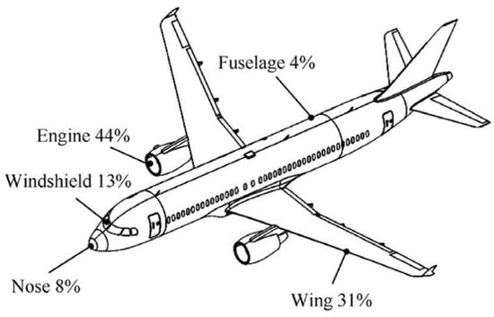
Figure 1.
The parts of an aircraft that might be damaged by birds [6].
The front-facing components of an aircraft that are susceptible to bird strikes include the windscreen, wing leading-edge section, wing flaps, and other auxiliary units [7,8]. Due to the huge air intake of aero-engines, revolving fan blades have one of the highest probabilities of being struck by birds. The leading edges of a blade, which can severely damage the bird projectile and the impact contact area [9], are always mentioned as the most susceptible regions in real, complicated, twisted fan blades under bird-strike impacts.
In order to confirm numerical models, Lavoie et al. [10] performed bird impact experiments using gelatin in place of real birds. They also pushed the use of numerical tools in the design and certification of aircraft. Numerical simulation has been shown to be an effective alternative way to design and certify a bird-strike-resistant component more economically due to the rapid advancement of computer technology and the finite element method. To simulate a bird-strike scenario, Vijay et al. [11] created multiple bird models and compared Lagrangian, arbitrary Lagrangian–Eulerian (ALE), and smooth particle hydrodynamic (SPH) approaches. This class of issue has been handled using explicit nonlinear finite element (FE) codes, which are accessible in various high-end commercial FE solvers.
Bird-strike experiments were also conducted by Hanssen et al. [12] on a double-sandwich panel, who created a mathematical model to replicate the testing procedure. Their results indicate that the finite element (FE) method could accurately represent the failure of aluminum foam cores and cover plates. More recently, Georgiadis et al. [13] invented a simulation technique to support the certification against bird strikes of the Boeing 787 Dreamliner’s adjustable trailing edge made of a carbon–epoxy composite. The bird was modeled using the SPH method, and the joints were represented by several advanced fastener elements in their work, and they used the explicit finite element program, PAM-CRASH. For upcoming experimental research on laminated composite blade prototype models using genuine aeronautical structures, the results in [14] are intended to serve as an approximate design guideline.
The International Bird Strike Research Group strongly recommends that the bird model, once standardized, becomes the standard for all further bird impact testing. Standardizing the geometry of the artificial bird model is, likewise, significant from the perspective of simulation. Both the bird configuration and the aspect ratio have been discovered to be critical components that influence the target’s impact response [15] on square plates with a hemispherical steel indenter. Static, low-velocity (up to 10 m/s), and high-velocity (up to 100 m/s) impact tests have been performed [16,17]. It was discovered that glass-fiber-based FMLs (fiber–metal laminates) have outstanding impact resistance, which is equal to or superior to monolithic aluminum alloys (depending on the layout) and significantly superior to carbon/epoxy composites. It was also observed that at higher strain rates, impact resistance improved. The high-impact performance of glass fiber FMLs can be attributed to a favorable high strain rate strengthening phenomenon that occurs in glass fibers, in combination with their relatively high failure strain. Because of this impact performance, it has been proposed that glass-based FML may be a suitable material for aircraft parts that are likely to be subjected to high-velocity impacts from objects such as runway debris or birds.
The author has continued to work on a number of technologies that could make composite fan blades lightweight or more efficient, for example, the feasibility of inserting thin foam inserts inside the composite blade, as well as any optimization of their geometry or shape to minimize failure due to delamination, the feasibility of using wavy trailing-edge technology to improve aero efficiency in unsymmetrically laid out composite blades, etc. [18,19,20,21,22].
According to this literature review, there has not been any new or published research that is highly relevant to design improvements in composite fan blades incorporating more than one fiber. The current study’s major goal is to eliminate the delamination issue that has been noticed on the trailing edge of composite fan blades when it is subjected to bird strikes on the leading edge. To accomplish this, separate glass composite zones within a carbon composite fan blade are proposed, as shown in Figure 2.
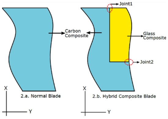
Figure 2.
Proposed plan [23].
For laminated composites, strain-based failure is always used to study delamination-type failure. Hence, everywhere in the simulations, the initiation of damage is considered by monitoring the level of the interlaminar type of failure. The progression of damage is not considered. The front portion of the engine fan blade is not subjected to high temperatures. Hence, all the simulations performed here do not consider the temperature effect.
2. Materials and Methods
No directly relevant research has been published on the design improvement in composite fan blades using hybridization. It is suggested that the parts of the carbon composite fan blade that are prone to delamination be covered with a material with better strain capability, such as glass fibers, while the remaining portion of the blade should be kept constant as carbon composite, as shown in Figure 2.
2.1. Bird Properties
At low speeds, the mechanical characteristics of normal avian bird tissues are neither uniform nor homogeneous. However, as a bird travels at higher speeds, this nonuniformity and inhomogeneity become less significant, and it may be fairly assumed that it is a homogenous jet of fluid striking a structure [23]. The material properties of a bird in deformation are frequently described using various hydrodynamic models. A recent study [24] revealed that the Mooney–Rivlin hyperelastic material model of ballistic gelatin can be a good substitute to create realistic bird impact scenarios. When analyzing the damage to aerostructures, the Lagrange–Mooney–Rivlin model can be used with reliability. It produced a similar impact [25] with the SPH water EOS model, despite some variances observed during the damage predictions. Mooney–Rivlin parameters are utilized in simulations, as shown in Table 1.

Table 1.
Mooney–Rivlin parameters.
The maximum bird mass allowed by the existing bird mass standards for bird–aircraft hit scenarios is 4.3 lb (or 1.95 kg) for the bird. Three geometric bird models have been widely used to simulate bird strike incidents in general: cylindrical with a straight end, hemispherical cylindrical with a hemispherical end, and ellipsoid. A straight-ended cylindrical bird with a radius of 60 mm and an overall length of 180 mm was used for the current numerical investigations to obtain a bird weight of around 1.97 kg. The relative velocity of the bird was calculated as 225 m/s using a cruising speed of 300 km/h and a fan blade rotating speed of 3000 RPM. Its starting velocity in the normal Z-direction was set to 225 m/s, and its initial mass density was set as 968 kg/m3. The 3D 8-node fully integrated explicit solid elements used for the meshing of the bird model, with a total of 4137 elements, were found to allow fast simulation runs without compromising accuracy.
2.2. The Flexible Fan Blade
A fan blade with the original specifications was designed in the SolidWorks application and then was imported into the hyper mesh to obtain the necessary mesh type with the desired number of elements. The fan blade was meshed and then imported into Ansys Workbench for explicit dynamic analysis. The fan blade incorporates the selected optimized joint design from earlier work on the sub-element and plate-level analyses.
A carbon and glass epoxy composite was utilized in the fan blade, as shown in the proposed plan, and a titanium alloy (Ti6Al4V) was used for the cap on the leading edge of the fan blade; the properties are listed in Table 2. Figure 3 shows a schematic representation of an isometric view of a bird strike on the leading edge of a flexible fan blade, as well as top and bottom views of a fan blade. The dimensions of the fan blade used are 550 × 1050 × 7.5 mm (based on the real fan blade size). Although, in a real blade, the thickness dimensions span- and chord-wise also vary, in this research, it is approximated as a constant thickness. The three bird impact locations were considered, as shown in the figure: at 80%, 60%, and 40% of the fan blade height from the bottom, and the glass composite joint in the span direction was also considered as 80%, 60%, and 40% of the overall length of the fan blade, as shown in Figure 4.

Table 2.
Material properties.
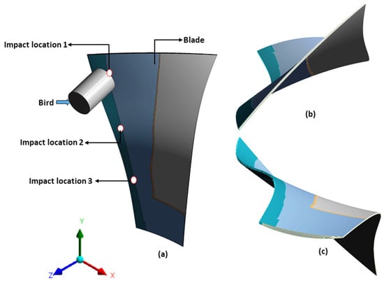
Figure 3.
Schematic diagram of a bird striking a flexible fan blade. (a) Isometric view, (b) top view, and (c) bottom view.
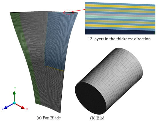
Figure 4.
Meshed model.
Figure 4 shows a meshed model of the fan blade and the bird. The blade is modeled here with twelve laminated layers based on the composite blade’s actual thickness in the area of the interface. The different color shades represent different orientations (mostly combinations of 0 and 45). In the mid-thickness region of the fan blade, continuous carbon fiber (0-degree orientations) layer components of different orientations are used to provide adequate strength. The lengths of the glass and carbon fibers in the joint region vary layer by layer, depending on where the joint in every layer is located. A 3D model with the above dimensions was created using the Solid185 element type, as shown in Figure 3. The planned fiber orientation [0°/45°/0°/−45°] in every layer was assigned using a system of local coordinates.
2.3. Material Properties
The materials used for the fan blade are carbon fibers–epoxy [26] and glass fibers–epoxy [27], and titanium alloy was used for the cap on the leading-edge side of the fan blade. The carbon and glass fiber composite properties used follow a fiber volume fraction of 60%. The properties for these materials are listed below in Table 2.
3. Results
Coupon, sub-element, and plate-level analyses have already been investigated [28,29] under static and dynamic conditions to identify the optimal joint according to lower interlaminar shear strain. From all these analyses, the best interface joint designs were shortlisted based on lower interlaminar shear strain, and the three best joints from both static and dynamic analyses based on the lowest level of maximum interlaminar shear strain were identified, as shown in Table 3.

Table 3.
Shortlisted cases.
3.1. Dynamic Analysis for the Plate with the Original Dimensions of the Fan Blade
All three of the shortlisted cases were designed using the full fan blade dimensions and joint designs, and a dynamic study was performed using Ansys Explicit Dynamics, with a bird velocity of 225 m/s. Three impact locations were considered in all three joint cases, as shown in Figure. Interlaminar shear strains were measured at each joint location in each of the shortlisted designs, and the results were normalized by calculating εxz/εx. All simulations were performed, and the response surface method was studied to identify the best joint out of the shortlisted cases. The results show that the shortlisted case, 1006, performs better than the other two shortlisted cases in all impact locations.
In the present work, blade-level analysis was performed for one shortlisted case (1006) from the plate-level analysis. The design of the shortlisted case, as shown below in Figure 5, was incorporated into the design of the fan blade and analyzed using the explicit dynamics of Ansys Workbench.
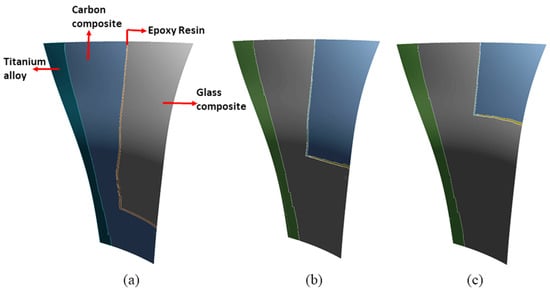
Figure 5.
Glass composite region variations: (a) 80%, (b) 60%, (c) 40% of the original length.
A fan blade model with the above design along the thickness view was created with a [0°/45°/0°/−45°] orientation, and the bird was created as a cylindrical model with flat ends and a two-to-three length-to-diameter ratio. This involves a single 4-pound (1.97 kg) bird, the properties of which are shown in Table 2. In this particular instance, we chose a bird striking a target at a speed of 225 m per second.
3.2. Deformation of the Blade in Z-Direction with Different Impact Locations
At the bottom region of the fan blade, the fixed boundary condition was used (mimicking the fixation of the fan blade base to the rotary hub of the engine), and all deformation, directional deformation, normal strains, and shear strains in the joint regions were monitored for the fan blade at the maximum impact velocity of the bird. The centrifugal forces due to the rotation of the fan blade were not considered here as it is negligible compared to the bird strike loading. Additionally, the air pressure load coming onto the fan blade was also neglected as it is also very negligible compared to the bird strike loading. The design criterion for fan blades is always resistance to a bird strike. The deformation of the fan blade in three cases is shown below in Figure 6. The maximum deformation of the blade in three impact locations is listed in Table 4. Figure 7 shows the joint configuration of the shortlisted case 1006.
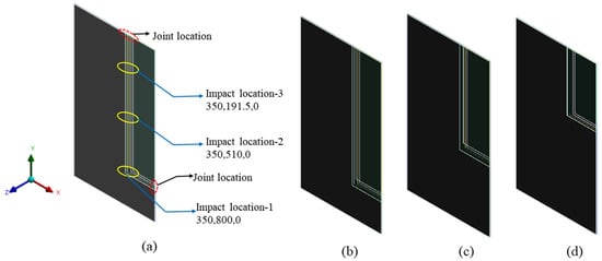
Figure 6.
(a) Impact location and joint length: (b) 80% length, (c) 60% length, (d) 40% length.

Table 4.
Deformation of blade in three impact locations.

Figure 7.
Shortlisted case 1006.
As demonstrated in Figure 8 and Figure 9a, there is little difference in overall plate deformation for the same impact location. Additionally, maximum deformation does not vary much for the different joint locations. This may be attributed to the high-speed bird strike event, which clearly suppresses other local material variations in terms of deformation. Table 4 shows the highest deformation at the end time of 0.0015 s. However, strain variation shows different patterns. Figure 9b shows the normalized interlaminar strain variation for a particular simulation case scenario; in this case, the joint length is fixed at 60%, and the impact location is varied. If we observe carefully, it can be concluded that the shortlisted design exhibits the best results with the joint at 40% length, i.e., lower levels of normalized interlaminar shear strains at all impact locations with the same velocity and bird weight. The normalized strain values with different joint lengths at all three impact locations are listed in Table 5. Figure 10 shows the interlaminar strain variations inside the joint region of the fan blade for one sample case.
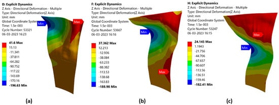
Figure 8.
Deformation of blade in the case of 60% length: (a) impact location 1, (b) impact location-2, and (c) impact location-3.
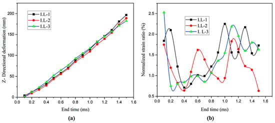
Figure 9.
(a) Deformation and (b) strain behavior in the case of three impact locations for 60% of the joint length.

Table 5.
Strain variation with respect to impact location.
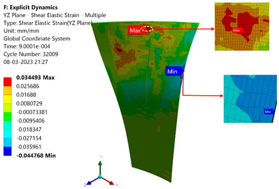
Figure 10.
Interlaminar shear strain level for joint at 60% length [0°/45°/0°/−45°] orientation.
4. Response Surface Method
The response surface method (RSM) is capable of helping to design and optimize the experiment. RSM is a statistically accurate and intelligent mathematical technique for developing and improving experiments by allowing the best parameters to be chosen after a minimal number of repetitions. The RSM, which was originally utilized in empirical investigations, has recently been used in numerical studies. Yet, because of its helpful qualities, such as drastically decreasing computational costs and forecasting nonlinear optimization processes, it has become a popular approach in numerical studies.
4.1. Design Variables and Objective Functions
In this work, two design variables, including impact location and joint length variation, and one response were selected for optimization. In addition, as listed in Table 6, each design variable has three levels, and the impact location changes the distance from location-1 to location-3, as shown in Figure 3. Additionally, the joint length varies from 80% of the blade length to 40% of the blade length, as shown in Figure 4. The purpose of this work is to study the behavior of joint design in fan blades with the selected design variables.

Table 6.
Design variables.
Analysis of variance (ANOVA) is used to test for significance in order to develop clear and simple regression models between design parameters and objective functions and to evaluate the fitness of regression models. The R2 values, which are calculated by dividing the sum of squares from the regression model by the sum of all squares, are used to measure how well the regression model fits the data. The F- and p-values indicate the significance of terms in the regression model. The F-value is calculated as the ratio of the mean squares of the factors and errors, whereas the p-value represents the probability that the F-test will be successful. The most significant model usually has a low p-value and a high F-value.
4.2. Analysis of Variance (ANOVA)
Table 7 lists the analysis of variance analyses for the response R1 (εyz/εy) and R2 (εyz/εx). It can be observed in Table 7 that R2 for εyz/εy is 96.63%, which means that 96.63% of the variation in εyz/εy is due to the three factors, so the total variation can be well reflected by the quadratic model.

Table 7.
ANOVA table.
4.3. Response Surface Model Fitting and Error Analysis
Design–Expert software’s final predictive equations for the response factor (R1) are shown below. It should be noted that the units for the parameters in the following equation are the same as those listed in Table 6. Figure 11 presents diagnostic plots to evaluate the model’s statistical appropriateness. To assess the adequacy of the RSM-presented prediction model, a variety of diagnostic plots are given. In reality, some of these plots are shown in this study, which can be approximated using Design–Expert software.
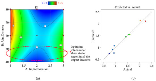
Figure 11.
(a) Interaction impact of design variables on R1; (b) predicted values vs. actual values.
R1 = −0.21 − 2.306 * Impact Location + 0.128 * Joint Distance − 0.016 * Impact Location * Joint Distance + 0.753 * Impact Location 2 − 0.00079 * Joint Distance 2
Figure 11a shows the interaction of all design variables with response factor R1 (εyz/εy), and Figure 11b shows a comparison between the numerical simulation results and the projected RSM outcomes. Here, three impact locations are considered, and the joint distance is in % of the original length of the blade. From this analysis, it can be concluded that the joint distance, 40% length, shows the normalized interlaminar shear strain level as minimum in all three impact locations. The predictive values are taken from the above equation and plotted in a comparison graph between these values and the simulation results; it shows as almost equal in both cases.
5. Discussion
As explained earlier, this is a progressive work, the earlier part of which was already published or accepted to be published [28,29]. The quasi-static coupon (with the joint interface built in there) level modeling and test validation were already performed, and the modeling method, along with boundary conditions, was validated with the test results, while the joint design was optimized by varying joint configurations. In the coupon-level static analysis, all 120 coupons were created for all possible joint configurations. For 120 possible configurations, when the displacement load was at its highest, all directional strains at the crucial joint locations were tracked both experimentally under a four-point bend configuration and using finite element analysis of the same coupon. Coupon joint models with the least amount of interlaminar shear strain among all designs were chosen for further consideration. For validation of the simulation results, a few coupons with a specific joint configuration were manufactured and tested. The delamination originated at the same joint location in the tests, where, in simulation, strain hotspots were seen. The strain hotspots in the experiments were seen using 2D digital image correlation strain contours. This validates the modeling methodology used for the coupon with a spliced joint.
Later, further analysis was performed using plate-level bird-strike analysis, where the optimized joint designs were incorporated into the plate (dividing the plate into carbon and glass composite areas). Finally, as a blade is much more complicated than a flat plate (it is curved in both chord-wise and span-wise directions), a blade model was created in the current research with one of the most promising interface joint designs incorporated inside the model, with the carbon and glass regions being clearly defined. The current work tries to validate the optimum interface joint design workability on the scale of blade-level models. Two design parameters (impact location and interface joint region length) were studied using the response surface method, and their effect on the output, that is, the interlaminar strain level, was investigated. The flexible blade progressively receives kinetic energy from the bird. At this time, when kinetic energy is converted into internal energy in the flexible blade, the total kinetic energy reduces. The hourglass energy of the entire system in the current analysis was just 4% (or less) of the overall energy. The regression equation was obtained, which can be used to predict the output for any values of the two design input parameters. The shortlisted optimized joints do show that the blade will survive the bird strike loading at most of the impact locations and for various glass composite region configurations. As can be seen from the results, the smaller glass composite regions, of course, show low levels of interlaminar shear strain for all three impact locations, and hence, a smaller region is recommended. Impact location-3 and joint region 80% show the lowest levels of interlaminar shear strain, but the blade should be good under all impact locations, and hence, smaller glass composite regions are recommended. This continued work shows the possibility of developing hybrid composite blades successfully and, hence, could lead to solving the issue of delamination on the trailing edge of the composite fan blade when subjected to bird strike loading.
6. Conclusions
A hybrid composite fan blade was proposed to avoid delamination on the trailing-edge region caused by bird strikes. The shortlisted hybrid interface joint design from the coupon- and plate-level analyses was incorporated into the composite fan blade model, and explicit dynamic analysis in Ansys Workbench was performed with a bird weight of 1.97 kg at a velocity of 225 m/s, considering three impact locations and three different joint regions of glass composite in the fan blade. The response surface methodology was utilized to find the best solution by adjusting parameters such as impact location and joint region length. Based on the results, the glass composite region length at 40% (smaller glass composite region) shows the optimum level of interlaminar shear strain under all impact locations.
Author Contributions
Methodology, G.Y., P.J. and C.L.; Software Validation, G.Y.; Formal Analysis, G.Y.; Investigation, G.Y.; Resources, G.Y.; Data curation, G.Y.; Conceptualization, P.J.; Original draft preparation, P.J.; Writing—Review & Editing, P.J.; Supervision, P.J. and C.L.; Project administration, P.J.; Funding acquisition, P.J. and C.L. All authors have read and agreed to the published version of the manuscript.
Funding
This research is partially funded SRM University internally in terms of resources. There was no external funding.
Data Availability Statement
The raw data with regard to this research is available with the authors. Feel free to contact the authors.
Conflicts of Interest
The authors declare no conflict of interest.
References
- Barber, J.P.; Taylor, H.R.; Wilbeck, J.S. Characterization of Bird Impacts on a Rigid Plate: Part 1; National Technical Information Service, U.S Department of Commerce: Alexandria, VA, USA, 1975.
- Husainie, S. Bird Strike and Novel Design of Fan Blades. In Proceedings of the 2017 Science in the Age of Experience, Chicago, IL, USA, 15–18 May 2017; pp. 26–40. [Google Scholar]
- Reddy, J. Finite element analysis of the initial stages of hypervelocity impact. Comput. Methods Appl. Mech. Eng. 1976, 9, 47–63. [Google Scholar] [CrossRef]
- Bin Rayhan, S. Finite element analysis of oblique bird strike on leading edge of aircraft wing. AIP Conf. Proc. 2018, 1980, 030009. [Google Scholar] [CrossRef]
- Budgey, R. The development of a substitute artificial bird by the International Birdstrike Research Group for use in aircraft component testing. In Proceedings of the 25th Annual Meeting of the International Bird Strike Committee, IBSC25/WP-IE3, Amsterdam, The Netherlands, 17–21 April 2000. [Google Scholar]
- Pahange, H.; Abolbashari, M.H. Mass and performance optimization of an airplane wing leading edge structure against bird strike using Taguchi-based grey relational analysis. Chin. J. Aeronaut. 2016, 29, 934–944. [Google Scholar] [CrossRef]
- Zhang, D.; Fei, Q. Effect of bird geometry and impact orientation in bird striking on a rotary jet-engine fan analysis using SPH method. Aerosp. Sci. Technol. 2016, 54, 320–329. [Google Scholar] [CrossRef]
- Mohagheghian, I.; Wang, Y.; Zhou, J.; Yu, L.; Guo, X.; Yan, Y.; Charalambides, M.; Dear, J. Deformation and damage mechanisms of laminated glass windows subjected to high velocity soft impact. Int. J. Solids Struct. 2017, 109, 46–62. [Google Scholar] [CrossRef]
- Sun, Y.; Zhang, Y.; Zhou, Y.; Zhang, H.; Zeng, H.; Yang, K. Evaluating Impact Damage of Flat Composite Plate for Surrogate Bird-Strike Testing of Aeroengine Fan Blade. J. Compos. Sci. 2021, 5, 171. [Google Scholar] [CrossRef]
- Lavoie, M.; Gakwaya, A.; Ensan, M.N.; Zimcik, D.; Nandlall, D. Bird’s substitute tests results and evaluation of available numerical methods. Int. J. Impact Eng. 2009, 36, 1276–1287. [Google Scholar] [CrossRef]
- Goyal, V.; Huertas, C.; Leutwiler, T.; Borrero, J.; Vasko, T. Robust Bird-Strike Modeling Based on SPH Formulation Using LS-DYNA. In Proceedings of the 47th AIAA/ASME/ASCE/AHS/ASC Structures, Structural Dynamics, and Materials Conference, Newport, RI, USA, 1–4 May 2006; Volume 3, pp. 2044–2061. [Google Scholar] [CrossRef]
- Hanssen, A.; Girard, Y.; Olovsson, L.; Berstad, T.; Langseth, M. A numerical model for bird strike of aluminium foam-based sandwich panels. Int. J. Impact Eng. 2006, 32, 1127–1144. [Google Scholar] [CrossRef]
- Georgiadis, S.; Gunnion, A.J.; Thomson, R.S.; Cartwright, B.K. Bird-strike simulation for certification of the Boeing 787 composite moveable trailing edge. Compos. Struct. 2008, 86, 258–268. [Google Scholar] [CrossRef]
- Zhou, Y.; Sun, Y.; Huang, T. Impact-Damage Equivalency for Twisted Composite Blades with Symmetrical Configurations. Symmetry 2019, 11, 1292. [Google Scholar] [CrossRef]
- Edge, C.H.; Degrieck, J. Derivation of a Dummy Bird for Analysis and Test of Airframe Structures. In Proceedings of the 1999 Bird Strike Committee-USA/Canada, First Joint Annual Meeting, Vancouver, BC, Canada, 10–13 May 1999; Available online: http://www.birdstrike.org/wp-content/uploads/2015/01/article1013contextbirdstrike1999.pdf (accessed on 23 March 2023).
- Vlot, A.; Kroon, E.; La Rocca, G. Impact Response of Fiber Metal Laminates. Key Eng. Mater. 1997, 141–143, 235–276. [Google Scholar] [CrossRef]
- Vlot, A. Impact loading on fibre metal laminates. Int. J. Impact Eng. 1996, 18, 291–307. [Google Scholar] [CrossRef]
- Jadhav, P. Innovative designs of embedded foam inserts in aerospace composite structures. Mater. Today Proc. 2020, 21, 1164–1168. [Google Scholar] [CrossRef]
- Jadhav, P. Effect of Ply Drop in Aerospace Composite Structures. Key Eng. Mater. 2020, 847, 46–51. [Google Scholar] [CrossRef]
- Jadhav, P. Feasibility of Composite Compressor Blade Using Sub-element Level Bird Strike Tests and Analysis. In Recent Advances in Applied Mechanics; Springer: Singapore, 2022; pp. 195–209. [Google Scholar] [CrossRef]
- Jadhav, P. Wavy Trailing Edge Feasibility for Aircraft Engine Composite Fan Blade. Mater. Sci. Forum 2022, 1060, 51–56. [Google Scholar] [CrossRef]
- Jadhav, P. Design Methodologies for Composite Structures in Aircraft Engines. In Advanced Composites in Aerospace Engineering Applications; Springer International Publishing: Cham, Switzerland, 2022; pp. 93–108. [Google Scholar] [CrossRef]
- Wilbeck, J.S. Impact Behavior of Low Strength Projectiles; Texas A&M University: College Station, TX, USA, 1977. [Google Scholar]
- Zhou, J. Experimental and Numerical Investigation of Soft Impact Loading on Aircraft Materials. Ph.D. Thesis, Imperial College, London, UK, 2017. [Google Scholar]
- Aslam, M.A.; Bin Rayhan, S.; Ke, Z.; Yu, W.J. Ballistic gelatin Lagrange Mooney-Rivlin material model as a substitute of bird in finite element bird strike case studies. Lat. Am. J. Solids Struct. 2020, 17. [Google Scholar] [CrossRef]
- Colvin, G.E., Jr.; Swanson, S.R. Mechanical characterization of IM7/8551-7 carbon/epoxy under biaxial stress. J. Eng. Mater. Technol. 1990, 112, 61–67. [Google Scholar] [CrossRef]
- Swapnil, A.S.; SatheSandip, B.; ChaudhariBapu, P.; Vishal, S.J. Experimental Investigation of Mechanical Properties of Glass Fibre/Epoxy Composites with variable volume fraction. Mater. Today Proc. 2017, 4, 9487–9490. [Google Scholar] [CrossRef]
- Yella, G.L.; Jadhav, P. Hybrid joint interface in composite fan blade subjected to bird strike loading. Part C J. Mech. Eng. Sci. in press.
- Jadhav, P.; Gruha, L.Y. Design and Optimization of Hybrid Interface Joint in a Composite Fan Blade of Aircraft Engine. IOP Conf. Ser. Mater. Sci. Eng. 2021, 1126, 012036. [Google Scholar] [CrossRef]
Disclaimer/Publisher’s Note: The statements, opinions and data contained in all publications are solely those of the individual author(s) and contributor(s) and not of MDPI and/or the editor(s). MDPI and/or the editor(s) disclaim responsibility for any injury to people or property resulting from any ideas, methods, instructions or products referred to in the content. |
© 2023 by the authors. Licensee MDPI, Basel, Switzerland. This article is an open access article distributed under the terms and conditions of the Creative Commons Attribution (CC BY) license (https://creativecommons.org/licenses/by/4.0/).