Article

Experimental Study on Reaction Kinetic Characteristics of RP-3 Fuel Vapor Catalyst

1
Jiangsu Key Laboratory of Process Enhancement and New Energy Equipment Technology, School of Mechanical and Power Engineering, Nanjing Tech University, Nanjing 211816, China
2
College of Aerospace Engineering, Nanjing University of Aeronautics and Astronautics, Nanjing 210016, China
3
Aviation Key Laboratory of Science and Technology on Aero Electromechanical System Integration, Nanjing Engineering Institute of Aircraft Systems, Nanjing 211106, China
*
Authors to whom correspondence should be addressed.
Aerospace 2023, 10(5), 410; https://doi.org/10.3390/aerospace10050410
Submission received: 12 March 2023 / Revised: 20 April 2023 / Accepted: 26 April 2023 / Published: 28 April 2023

Abstract

:
Oxygen-consuming inerting technology is expected to be the primary method for suppressing aircraft fuel tank fires and explosions in the next generation, with the catalytic reactor serving as its core component. However, the catalytic properties of the developed catalyst have yet to be thoroughly studied, and a primary reaction kinetic equation is needed to support further investigation of the reactor. Thus, this study focuses on the performance of the developed catalyst for RP-3 fuel vapor, with a test bench built to analyze its reaction kinetic characteristics. Initially, we tested the steady-state variation in the fuel vapor concentration (FVC) with fuel temperature and fitted an empirical equation, providing fundamental data for subsequent experiments. Subsequently, we studied the impact of critical parameters, such as the FVC, oxygen concentration (OC), CO2 concentration, and reaction temperature, on the reaction performance. The results demonstrate that the reaction rate is positively correlated with the FVC, OC, and reaction temperature, while CO2 has no impact on the catalytic reaction characteristics. Finally, a kinetic equation for the developed catalyst is summarized based on the experimental data, providing a fundamental equation for simulating research on the catalytic reactor and the oxygen-consuming inerting system.

1. Introduction

Fuel tank explosions and disintegration remain among the primary causes of aircraft accidents [1,2]. To address this issue, both the Federal Aviation Administration of the USA (FAA) and the Civil Aviation Administration of China (CAAC) have established airworthiness regulations mandating necessary measures to minimize fuel tank flammability [3]. Years of research have demonstrated that fuel tank inerting technology, which reduces the OC in the fuel tank ullage, is the most effective method for mitigating fuel tank flammability [4,5,6].
After several years of development, the Hollow Fiber Membrane On-Board Inert Gas Generation System (HFM-OBIGGS) has become the most commonly used inerting technology. For instance, the F-22, F-35, Boeing 737, Boeing 747, and Airbus A320 all employ this technology [7,8]. However, practical application has revealed several issues with this technology. Firstly, it requires a significant amount of high-pressure engine bleed air, resulting in increased aircraft compensation loss. Secondly, the membrane separation performance declines significantly, leading to low nitrogen production efficiency and a short service life. Thirdly, the release of fuel vapor causes environmental pollution and violates the global carbon neutrality strategy [9,10].
In light of these issues, researchers have proposed several new inerting methods, such as adsorption inerting technology [11], cooling inerting technology [12], oxygen-consuming inerting technology [13], and others. Among them, the oxygen-consuming inerting technology is the most likely to be applied in the next generation of on-board fuel tank inerting technology, owing to its high inerting efficiency and enhanced security [14]. Unlike the “first-generation” oxygen-consuming inerting system in the 1960s, fuel catalytic inerting technology catalyzes the combustion of liquid fuel, resulting in more intense reactions with reaction temperatures reaching 700 °C, which is far more dangerous [15]. The “second-generation” oxygen-consuming inerting technology involves catalyzing the combustion of fuel vapor, with relatively lower reaction temperatures. For instance, the catalytic reaction temperature of the Green On-Board Inert Gas Generation System (GOBIGGS), proposed by the Phyre Company, is approximately 230 °C, lower than the spontaneous combustion temperature of RP-3 fuel vapor. This translates to enhanced safety and reliability. As illustrated in Figure 1, the basic principle of GOBIGGS involves extracting mixed gas from the fuel tank ullage into a catalytic reactor for low-temperature combustion. The reaction consumes fuel vapor and O2, producing CO2 and water. After the reaction, the inert gas containing large amounts of N2 and CO2 flows back to the fuel tank for inerting, after cooling and drying [16].
Parker Aerospace has developed a Jet-A fuel GOBIGGS prototype. In 2011, this prototype was installed in an A-3 attack aircraft empty fuel tank with a volume of 4.54 m3. Results from the research showed that the OC in the fuel tank ullage decreased from 21% to 9% in only 9.6 min [13]. This new inerting technology presents several advantages [17]. Firstly, there is no need to bleed air from the engine, and the energy consumption is much lower than that of the HFM-OBIGGS system. Secondly, the catalytic reaction temperature is low and can be kept in a controllable range even if the cooling system fails. Thirdly, since oxygen is consumed in the reactor, the inerting efficiency is high. Fourthly, the system is compact, lightweight, and highly integrated. Finally, minimal fuel vapor is discharged outside, making it environmentally friendly.
However, the compositions of various aviation fuels can differ significantly, and the characteristics of different batches may also vary [18]. RP-3 aviation kerosene is a mixed fuel composed of various hydrocarbon molecules, mainly alkanes with carbon atoms ranging from 10 to 16, including paraffins, cycloalkanes, aromatic hydrocarbons, and olefins, and the components of the fuel vapor are similar. The main components of RP-3 and Jet-A fuel are presented in Table 1 [19,20].
Research in the field of low-temperature catalysis shows that it is difficult to develop a universal catalyst due to the differences in material composition. Therefore, when applying the low-temperature catalytic inerting system to China’s RP-3 aviation fuel, it is necessary to develop other catalysts [21,22]. Studies have shown that some noble metals, particularly platinum, exhibit the best catalytic activity due to their significant ability to activate C-H and O-H bonds [23]. ZSM-5 zeolite-supported platinum was found to have superior performance in the catalytic combustion of toluene by Chen et al. [24], while Liu et al. [25] investigated the activity of various zeolite-supported Pt catalysts for soot oxidation, and reported that Pt catalysts can effectively promote the decomposition of hydrocarbons.
Based on these considerations, our research group prepared three types of all-silica-supported Pt nanoparticles, namely Pt/Si-Beta, Pt/Si-ZSM-5, and Pt/SBA-15, and evaluated their catalytic activity for the flameless combustion of fuel samples. The preliminary research results indicate that Pt/Si-Beta exhibits the most superior catalytic activity among these catalysts, enabling the complete combustion of methylcyclohexane and RP-3 aviation fuel at 166 °C and 241 °C, respectively. This remarkable performance of Pt/Si-Beta can be attributed to its exceptional hydrocarbon adsorption capacity. Additionally, taking into account the catalytic performance and cost-effectiveness of the catalyst, we found that a 1.0 wt% loading amount of Pt is suitable to meet the actual requirements of the inerting system. Moreover, Pt/Si-Beta showed excellent activity and stability over a prolonged period in varying humidity and air velocity environments, with a conversion rate of approximately 98% being maintained even after 30 h of continuous use [26].
The catalytic reactor is a crucial component of the low-temperature catalytic inerting system. However, research on the performance of developed catalysts is still limited. For instance, in the previous simulation study, the reactor performance was represented by a single catalytic efficiency since there is no primary reaction kinetic equation to support it [27]. Additionally, the actual vapor concentration of RP-3 fuel was often not considered, and the saturated vapor pressure was used instead [28]. The study of reactor performance and catalytic inerting system performance has been further affected by the lack of investigation on the reaction kinetic performance of the developed catalysts. Perego [29] provided a practical guide for kinetic studies of specific reaction systems, compared various laboratory reactors, and discussed the limitations and pitfalls in analyzing the effects of transport phenomena due to the flow, catalyst, and reactor geometry. Bakhtiari [30] studied the kinetics of equimolar oxygenated hydrocarbon vapor conversion over a catalyst in a packed-bed tubular reactor, where intrinsic kinetic data were collected in the absence of heat and mass transfer limitations. A kinetic model in power function form was developed with reaction orders of 0.6 and 0.8 for methanol and vapor, respectively, and an activation energy of 99 kJ/mol. Hao [31] investigated the kinetics of the hydrogenation of methylcyclopentadiene dimer (MCPD) to endotetrahydrodimethylcyclopentadiene over a Pd/C catalyst and analyzed the reactivity of the C=C bond in the MCPD molecule by density functional theory calculations using the Gaussian 03 series program. The kinetic model proposed is based on the Langmuir–Hinshelwood mechanism, taking into account the non-competitive adsorption between organic and atomic hydrogens. Todorova [32] prepared a Pd/Mn2O3 catalyst with high activity in the complete oxidation reaction of methane. Mn2O3 acts as high-capacity storage for oxygen species, keeping palladium in the oxidized state. The catalyst bed temperature for reaching 50% conversion at a water vapor concentration of 20,000 ppm and a gas time velocity of 25,000 h−1 was 430 °C, demonstrating high activity.
Hence, this study established an experimental platform utilizing the developed low-temperature catalyst [26] to investigate the kinetic properties of the catalyst using RP-3 fuel, and to establish a kinetic reaction equation that can serve as a reference for simulating the catalytic reactor and inerting system.

2. Experimental Principle and System

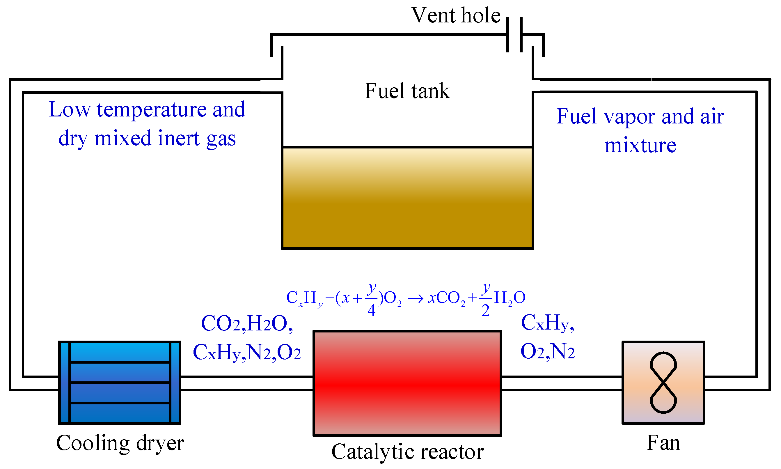
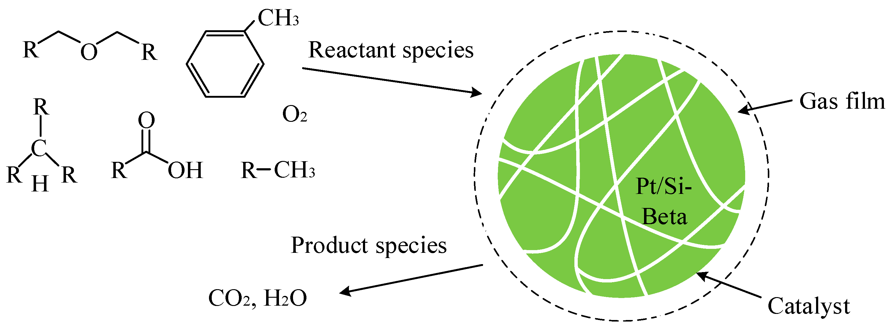
2.1. Experimental Principle

The suitable experimental methods for gas–solid phase catalytic reaction kinetics tests include integral and differential forms [33]. Considering the characteristics of the fuel vapor catalytic reaction and the available experimental conditions, the differential method was adopted for the experimental determination of the catalyst reaction kinetic equation. The basic principle is to determine the parameter value according to the reaction rate measured under various experimental conditions. Due to the low catalyst loading, the reaction rate and bed temperature gradient changes are minimal, resulting in nearly equal reaction rates in the catalytic reactor. Therefore, the data obtained can be considered under the conditions of isothermal and isoconcentration.
Chemical reaction kinetic equations commonly used include power function and hyperbolic function types. The power function form is widely used due to its simple mathematical processing, and the reaction rate constant is a function of temperature and conforms to the Arrhenius relationship [34]. Therefore, it can be assumed that the reaction kinetic equation form of RP-3 aviation fuel is represented by Equation (1). As RP-3 aviation fuel contains dozens of hydrocarbon components, to facilitate calculation and application and ensure that the total number of carbon atoms remains unchanged, the fuel vapor is converted into the total hydrocarbon concentration measured by C3H8.
r = k 0 e E R T n C 3 H 8 m n O 2 n
On the other hand, according to the definition of the reaction rate R, we have
r = 1 V cat n C 3 H 8 R T p Q η
The hydrocarbon conversion rate η can be calculated using the following equation:
η = n C 3 H 8 n C 3 H 8 out n C 3 H 8
where r denotes the catalytic reaction rate, mol/(m3·s). k0 denotes the pre-exponential factor, independent of the reaction temperature, and the unit is related to m and n. E denotes the activation energy, J/mol. R denotes the gas constant, 8.314 J/(mol·K). T denotes the reaction temperature, K. nC3H8, nC3H8out denote the molar concentration of fuel vapor expressed by C3H8 at the inlet and outlet of the reactor, mol/m3. nO2 denotes the molar concentration of O2, mol/m3. m, n are the power exponents. Vcat denotes the catalyst volume, m3. p denotes the reaction pressure, Pa. Q denotes the reaction gas flow rate, mol/s. η denotes the hydrocarbon conversion rate, no unit.
To obtain the kinetic equation of the reaction, the pre-exponential factor k0, the activation energy E, and the power exponents m and n must be determined. Using Equations (1) and (2), the catalyst volume and reaction gas flow can be fixed, and the fuel vapor conversion can be measured at the inlet and outlet of the reactor under different FVC, OC, and reaction temperatures. Subsequently, the four necessary parameters in Equation (1) can be fitted.

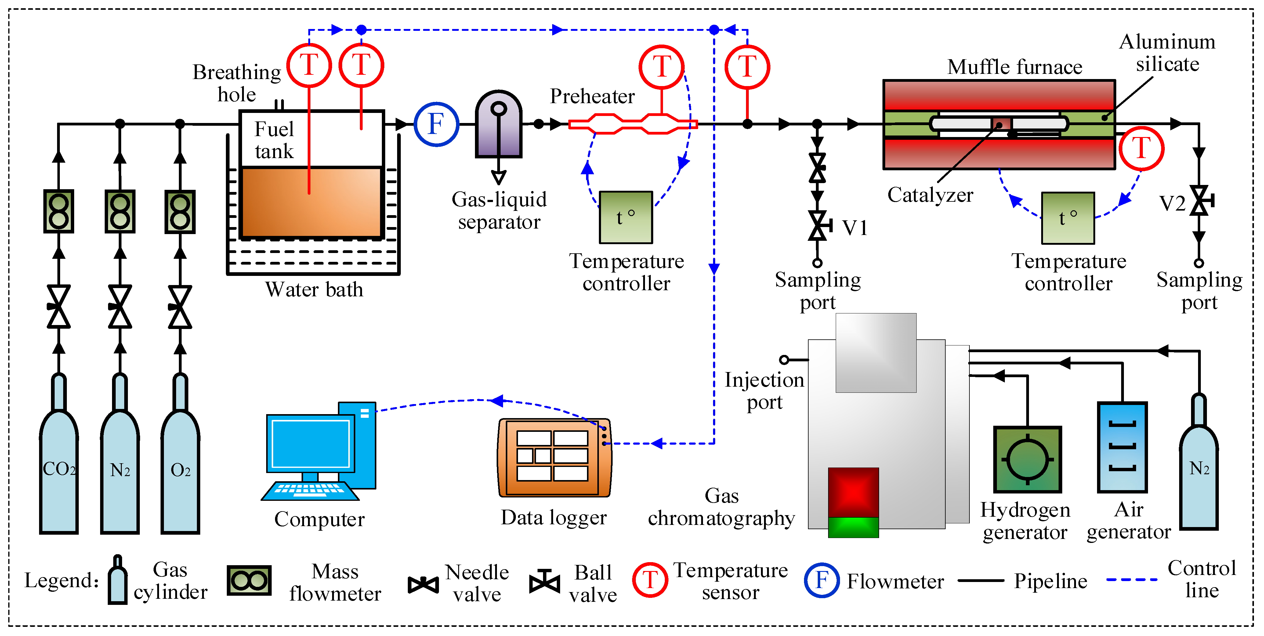
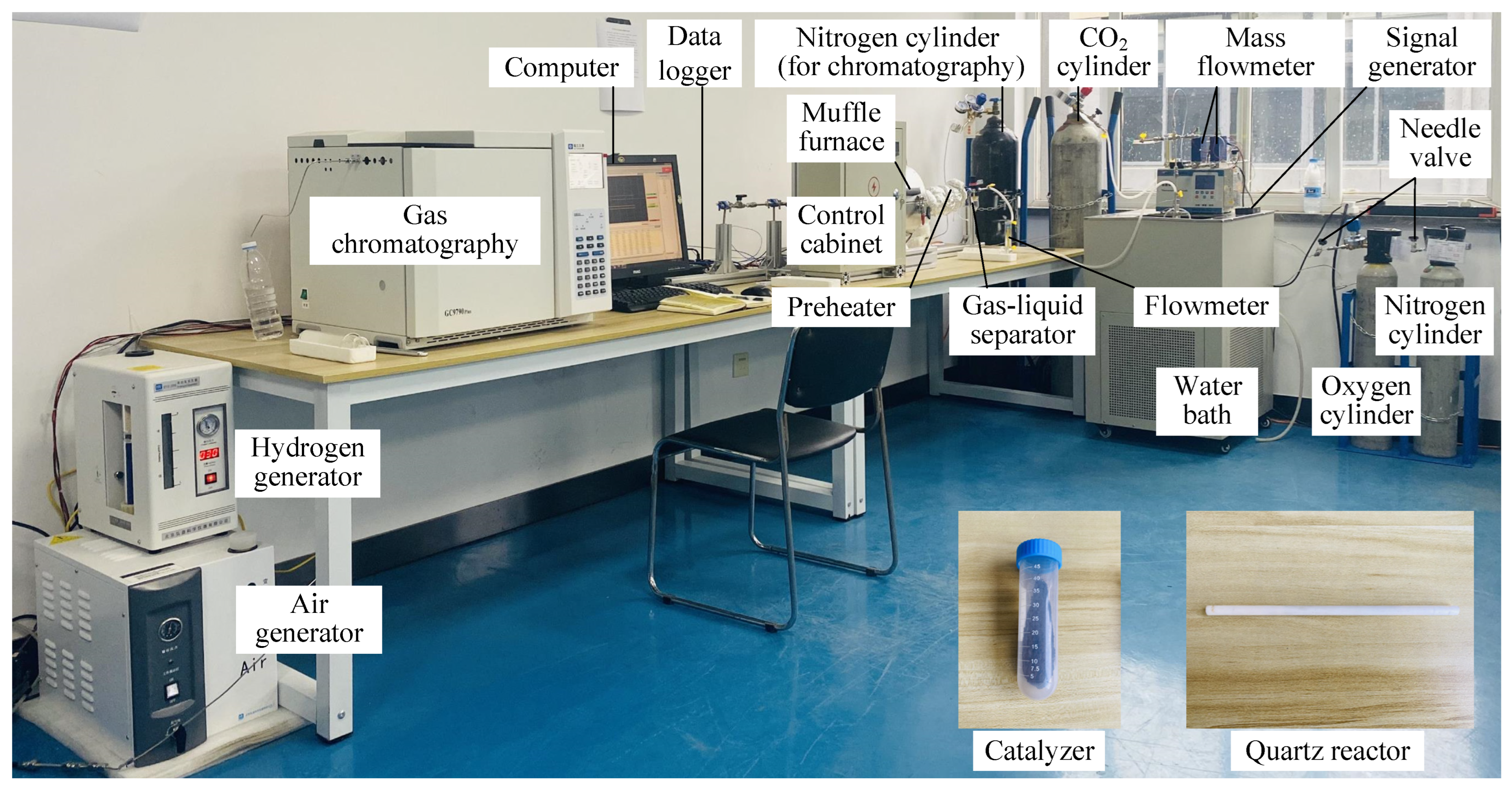
2.2. Experimental System

The system flow chart and experimental setup are depicted in Figure 2 and Figure 3, respectively. The experimental approach involves placing the fuel tank in a water bath (FDL Inc., Shanghai, China) maintained at a constant temperature for a prolonged period to ensure the continuous generation of fuel vapor at a steady rate. A mixed gas flow of adjustable composition comprising O2, N2, and CO2 is introduced over the fuel tank to prepare the reaction gas. The mixed gas stream passes through a gas–liquid separator (JGPC Inc., Xinxiang, China) to remove any liquid fuel that may be entrained in the fuel vapor before preheating to the designated temperature and subsequent introduction into the reactor for low-temperature catalytic reaction. The FVC at the inlet and outlet of the reactor is determined using a gas chromatograph (FULI Inc., Taizhou, China) equipped with a Flame Ion Detector (FID) with a maximum error of ±1% and a minimum detectable value of 1 ppm. Using these measurements, the conversion rate and reaction rate of the fuel vapor can be calculated.
As the gas flow rate is low, the fuel tank ullage replacement frequency is small, and the experimental fuel tank is placed in a constant-temperature water bath. The heat exchange of the fuel tank is sufficient, thereby ensuring a constant FVC before the reaction. Based on the set reaction gas flow, the FVC before the reactor, and the designed O2 and CO2 concentrations at the inlet of the reactor, the required O2, N2, and CO2 flows can be calculated, respectively. The mass flowmeter (SEVENSTAR Inc., Beijing, China) controls the output flow of each cylinder. Since the filled catalyst volume is only 0.1 mL, the dosage is minimal, and the reactor diameter is small, there is no longitudinal or transverse temperature gradient or concentration gradient of reactants. As a result, the gas in the reactor has a uniform FVC. To maintain a constant temperature in the reactor, a quartz tube (size DN8 mm × 100 mm) is placed in a muffle furnace, and the temperature controller (SHENPENG Inc., Shenzhen, China) regulates the temperature of the muffle furnace.
The gas and liquid temperatures of the fuel tank and the gas temperature before the reaction were recorded by a data logger (HIOKI Inc., Kagoshima, Japan) and processed by an industrial computer. The gases required for gas chromatography, namely N2, H2, and air, were provided by a 40 L N2 steel cylinder with a concentration of 99.999%, an H2 generator(HONGYI Inc., Beijing, China), and an air generator(HONGYI Inc., Beijing, China). The cylindrical fuel tank used in the experiment had a size of DN200 mm × 200 mm. The preheater was heated by an electric heating belt and controlled by a temperature controller. For the chromatography test, a static sampling method was employed, and each sampling gas’ volume was 100 mL to ensure that the flow and pressure of the standard gas and the sample gas were the same when entering the chromatography instrument. The test conditions for chromatography were 100 °C for the injection port, 80 °C for the column oven, 200 °C for the detector, and 80 °C for the auxiliary furnace.
The experiments may have uncertainties or errors arising from various sources, such as (1) possible deviations in controlling the flow rate of the reaction gas by the mass flow meter; (2) possible deviations in controlling the temperature of the water bath; (3) possible errors in measuring the concentrations of oxygen and hydrocarbon with the temperature sensor(SHENPENG Inc., Shanghai, China) and gas chromatography; and (4) possible errors in measuring the amount of catalyst used. These factors may lead to some differences between the actual experimental conditions and the designed conditions. To minimize the impact of uncertainty on the experimental outcomes, the fuel vapor concentration was measured three times under the same operating conditions, and the average value was taken as the final experimental result.
The main equipment parameters of the experiment are shown in Table 2.
The experimental procedure is described as follows:
  • Chromatography setup: Turn on the N2 cylinder, H2 generator, and air generator in sequence. Set the chromatographic conditions and ignite after reaching the set requirements.
  • Gas distribution: Turn on the N2, O2, and CO2 cylinders in sequence and adjust the mass flowmeter or needle valve to achieve the required experimental conditions, which is a total flow rate of 200 mL/min. Adjust the needle valve before the reactor to ensure consistent flow rates at the reactor inlet and outlet.
  • Setting experimental conditions: Turn on the constant temperature water bath and set the temperature value according to the experimental conditions. Turn on the muffle furnace and preheater heating and set the temperature value according to the experimental conditions.
  • Experiment and measurement: Start the experiment after completely replacing the gas in the fuel tank ullage and the pipeline. Turn on V1 and turn off V2, measure the FVC before the reaction, and repeat the measurement three times. Then, turn on V2 and turn off V1, measure the FVC at the outlet of the catalytic reactor, and repeat the measurement three times.
  • Changing experimental conditions: Change the fuel temperature, reaction temperature, preheating temperature, and gas distribution concentration of each gas according to the experimental working conditions to be carried out, and repeat step 4.
  • Experiment conclusion: Close the valves of the chromatography instrument, muffle furnace, preheater, constant-temperature water bath, and gas distribution cylinder when the experiment is completed.

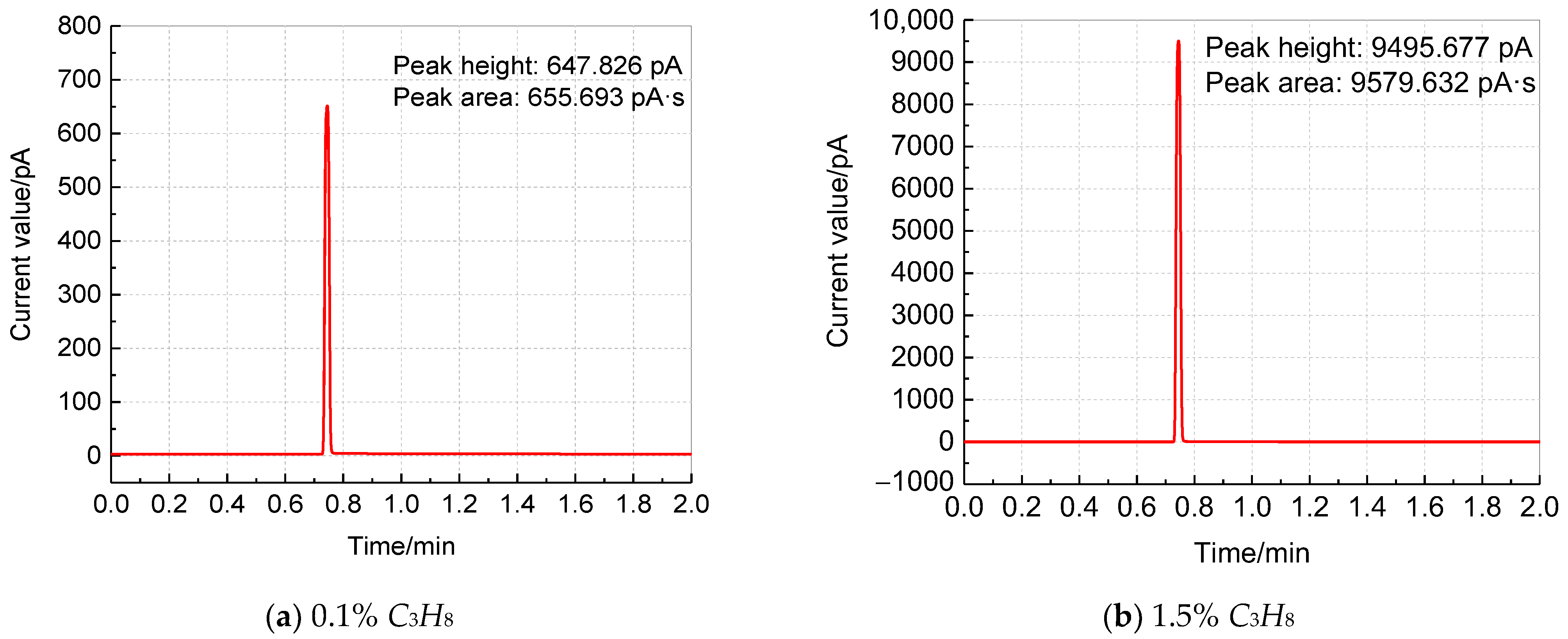
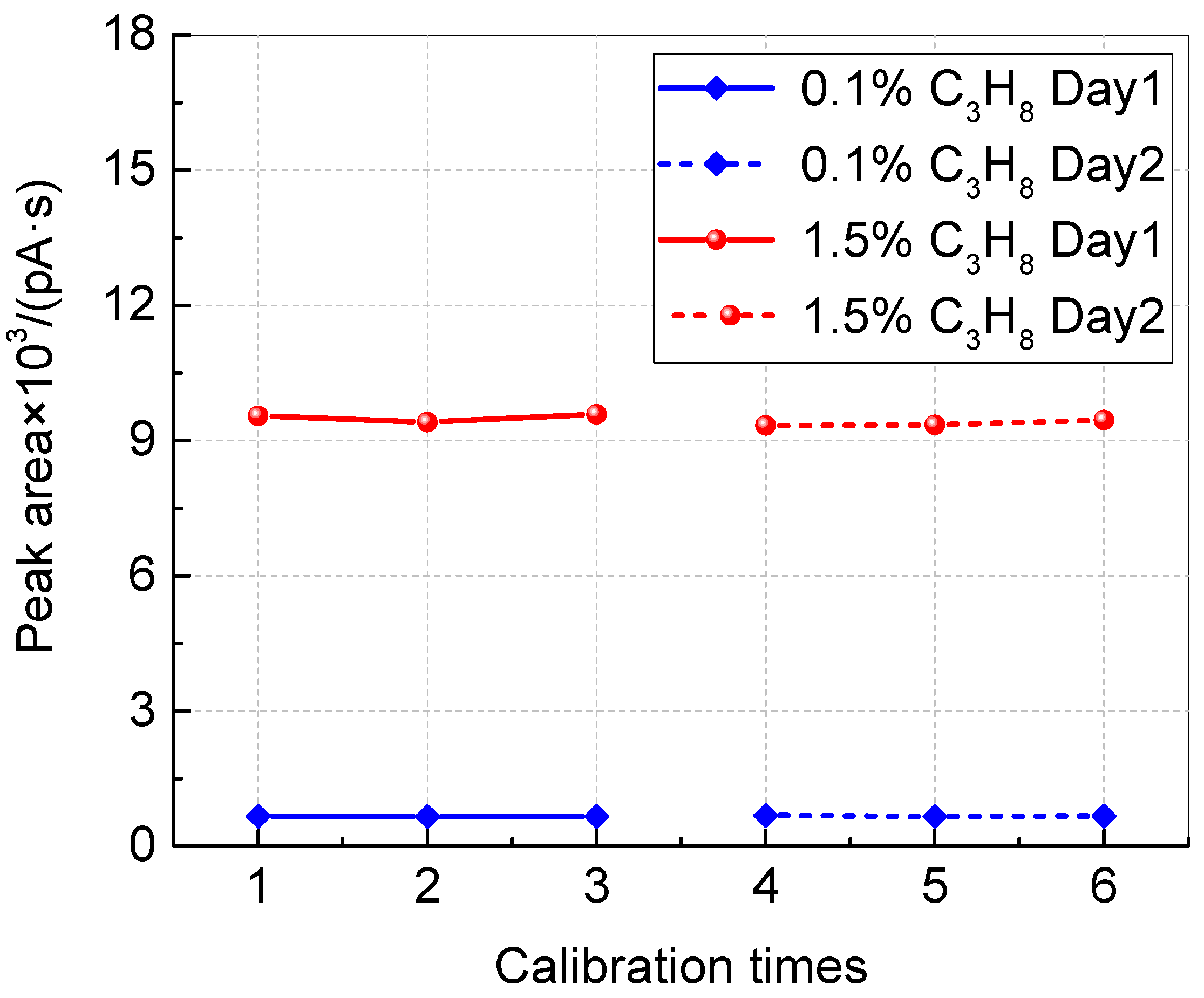
2.3. Chromatographic Calibration

Measuring the content of each element in aviation fuel is challenging due to its complex composition. Therefore, measuring the content of total hydrocarbons is more accessible and suitable for engineering applications. To measure the total hydrocarbons, the area normalization method was utilized. The basic principle of this method is that the total chromatographic peak area has a linear relationship with the FVC [35]. To calibrate the gas chromatograph, C3H8 standard gas of 0.1% and 1.5% concentrations was used. To ensure the accuracy of the calibration and eliminate accidental errors, the gas chromatograph was calibrated three times every 24 h for a total of 48 h. Figure 4 displays the chromatogram of the chromatographic workbench, where the prominent peak appearing 0.72 min after the start of injection detection is generated by the combustion of C3H8.
Figure 5 illustrates the reliable calibration results as the peak area of C3H8 standard gas with the same concentration remaining stable. Based on the calibration results of the chromatography, an uncertainty analysis of the fuel vapor concentration test is conducted. The A-type uncertainty S can be expressed using Equation (4):
S = i = 1 w ( C i C ¯ ) w ( w 1 )
The B-type uncertainty u can be expressed as in Equation (5):
u = Δ 3
Equation (6) expresses the combined uncertainty σ, which accounts for both the A-type uncertainty S and the B-type uncertainty u.
σ = S 2 + u 2
where Ci denotes the measured value and C ¯ denotes the average value of the fuel vapor concentration, %. The parameter w denotes the number of experiments, and ∆ denotes the minimum detectable limit of the apparatus, %. The uncertainty of the calibration results for both standard gases was calculated to be 0.58%.
Based on the results shown in Figure 5, the linear relationship between the FVC and the peak area can be expressed as in Equation (7) by taking the average value.
C C 3 H 8 0.1 % 1.5 % 0.1 % = A 662 . 310 9444 . 669 662 . 310
where CC3H8 denotes the fuel vapor volume fraction that converts into C3H8, %. A denotes the peak area of gas chromatography, pA·s.

3. Results and Discussion

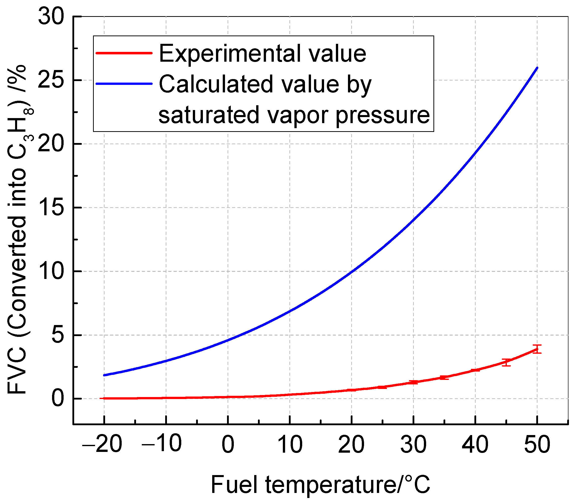
3.1. Relationship between RP-3 FVC and Temperature

The present study investigated the relationship between the FVC in the ullage of an RP-3 fuel tank and the fuel temperature under steady-state conditions. The results provide a reference for preparing reaction gas in experiments. To achieve this, the fuel tank temperature was controlled by adjusting the water bath temperature, and the FVC in the ullage was measured using a gas chromatograph when the fuel temperature was stable. The measurement was repeated five times, and the average value was taken. The results are presented in Figure 6. These experimental results were compared with the concentration values of RP-3 fuel calculated via the saturated fuel vapor pressure [36]. It is observed from Figure 6 that the FVC of RP-3 fuel increases with the rise in temperature, and the approximate exponential relationship is consistent with the changing trend of the calculated value. However, the actual FVC of RP-3 fuel is far less than the estimated value based on the saturated vapor pressure. For instance, when the fuel temperature is 40 °C, the two concentrations converted into C3H8 are 2.24% and 19.30%, respectively, with a difference of 8.6 times. Therefore, the saturated vapor pressure cannot be used to calculate the FVC. Additionally, this paper uses the expression equation of saturated vapor pressure for reference to fit the equation of the experimental FVC value of RP-3 with the fuel temperature, as shown in Equation (8).
lg ( C C 3 H 8 ) = 109.922 471788.063 t 4319.001
where t denotes the liquid fuel temperature, °C.

3.2. The Effects of Key Parameters on Kinetic Characteristics

Understanding the law of influence of the OC, FVC, and reaction temperature on the catalyst reaction kinetics is crucial for obtaining the reaction kinetic equation. Therefore, this paper conducted a cross-experimental study with the experimental parameters shown in Table 3. The fuel vapor concentration was measured using the gas chromatograph at the inlet and outlet of the reactor, and the conversion rate and reaction rate were calculated.

3.2.1. Effect of Reaction Temperature
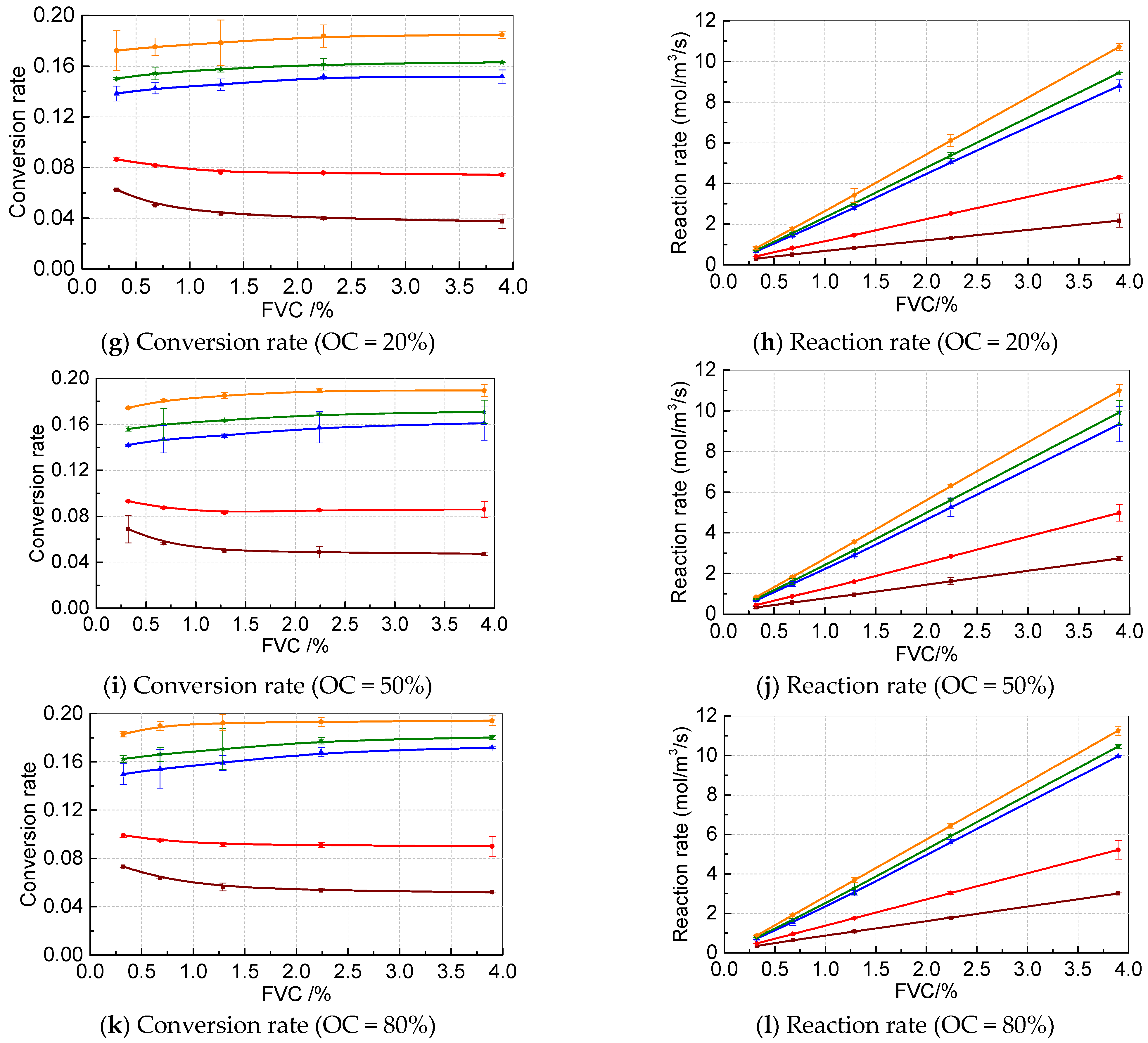
Figure 7 depicts the reaction schematic diagram, which provides a better understanding of the mechanism of catalytic reactions. Initially, the mixture of hydrocarbons and oxygen diffuses through the gas film outside the catalyst particles and reaches the catalyst surface or enters the internal pores. Under the influence of the catalyst, the catalytic reaction takes place and breaks down into CO2 and H2O. The reaction products then diffuse out of the pores and exit the reactor with the airflow. The experimental data were plotted with the FVC as the abscissa under different OCs and reaction temperatures, as shown in Figure 8. As shown in Figure 8, the conversion and reaction rates increase with the increase in reaction temperature. This outcome can be attributed to the intensified molecular movement and the enhanced catalyst performance at higher temperatures, resulting in an increase in the conversion and reaction rates. Under the experimental conditions, the maximum conversion rate of fuel vapor ranges from 0.056 to 0.192 as the reaction temperature rises from 150 °C to 250 °C.

3.2.2. Effect of OC

Furthermore, the conversion rate and reaction rate exhibit an increasing trend with the increase in OC, and the numerical relationship resembles an exponential function with a power index of less than 1, under the condition that the reaction temperature and FVC remain constant. This can be attributed to the fact that when the FVC remains constant, the increase in OC leads to more oxygen being adsorbed on the catalyst surface, resulting in more fuel vapor being consumed in the reactor. Moreover, three repetitions of each working condition were carried out, and the relative errors of the experimental values within the same group were all within 10%.

3.2.3. Effect of FVC

It is evident that the reaction rate increases gradually with the increase in FVC, and the relationship between them is approximately linear. This is attributed to the fact that a higher fuel vapor concentration corresponds to a greater concentration of vapor participating in the reaction, resulting in a higher amount consumed per unit time. However, as shown in Figure 8, the relationship between conversion and FVC is dependent on the reaction temperature and OC. When the reaction temperature is below 175 °C, a lower FVC leads to a higher conversion rate. However, when the reaction temperature exceeds 200 °C and the OC surpasses a critical value, the conversion rate increases with the increase in FVC, and the critical OC decreases as the reaction temperature rises. For instance, when the reaction temperature is 200 °C and the OC is 2% and 5%, the conversion rate decreases as the fuel temperature increases. Nevertheless, when the reaction temperature is 250 °C, only when the OC is 2% does the conversion decrease with the fuel temperature increase. This result is due to the weak reaction intensity when the reaction temperature is relatively low. Despite the increase in fuel vapor concentration, the amount of fuel vapor that can participate in the reaction is limited, causing a decline in the conversion rate. At this point, even a low concentration of O2 is sufficient to fulfill the amount of O2 required for the reaction. Furthermore, as the reaction temperature exceeds 200 °C, the catalyst’s activity is enhanced, and more fuel vapor can react, indicating an increasing trend in the conversion rate with the FVC increase. However, this trend is subject to the availability of O2 to participate in the reaction.

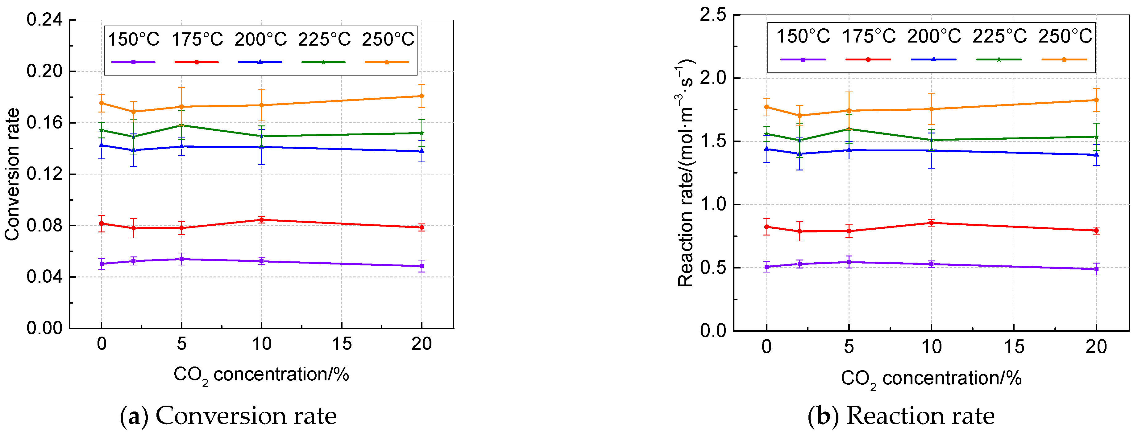
3.2.4. Effect of CO2 Concentration

The catalytic inerting system consumes fuel vapor and O2, generating CO2 and water vapor. Therefore, it is crucial to investigate the effect of CO2 on the catalyst. Figure 9 depicts the conversion rate and reaction rate of fuel vapor at a constant fuel temperature of 20 °C, O2 concentration of 20%, and residual N2 at different reaction temperatures. It is observed that the maximum error relative to the average value of each group is 5.78%, indicating that CO2 does not significantly impact the catalytic performance of the catalyst. The slight deviation in the outcome may have resulted from gas distribution and chromatography measurement errors.

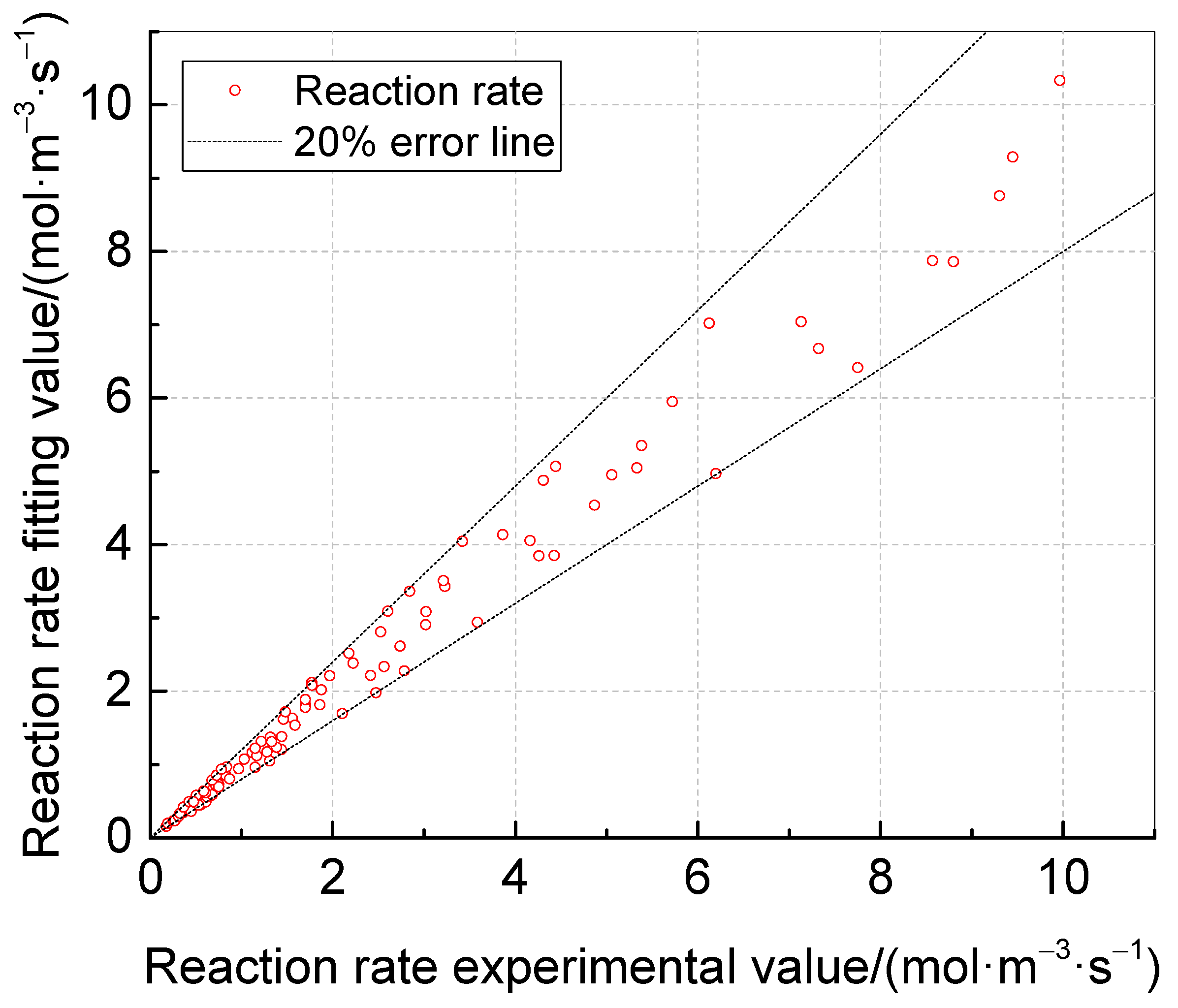
3.3. Reaction Kinetic Equation

The kinetic reaction equation was fitted using experimental data with an OC of no more than 20%, as the OC in the fuel tank ullage is not expected to be higher than this in the air. Equation (6) shows the resulting equation, which was determined using the 1stOpt software. The pre-exponential factor k0 of the equation is 6902.863 mol/(m3·s), the activation energy E is 28,749.160 J/mol, and the power exponents m and n are 0.996 and 0.238, respectively.
r = 6902.863 e 28749.160 R T n C 3 H 8 0 . 996 n O 2 0 . 238
The experimental data and the calculated theoretical values were plotted in the same image, as shown in Figure 10. The error was found to be within 20%. Since the catalytic reactor typically operates in the low OC range, neglecting the working condition at high O2 concentrations will lead to even smaller errors, making it suitable for subsequent reaction simulation calculations.

4. Conclusions

  • The results of this study indicate that the FVC of RP-3 increases with temperature, although its value is much lower than the value calculated based on the saturated vapor pressure. At 40 °C, the difference is as much as 8.6 times. Thus, using the saturated vapor pressure for FVC calculation is not feasible. Moreover, the experimental data reveal that the relationship between the RP-3 FVC and fuel temperature can be expressed by the equation lg ( C C 3 H 8 ) = 109.922 471788.063 t 4319.001 . These findings have practical implications for the accurate calculation of the FVC and the optimization of the design and operation of fuel systems.
  • The critical parameters that affect the catalytic reaction characteristics have been investigated. It was found that increasing the FVC, OC, and reaction temperature is beneficial to the catalytic reaction. Furthermore, it was determined that CO2 does not have a significant impact on the catalyst performance.
  • The derived kinetic reaction equation for the catalyst developed for the RP-3 aviation fuel oxygen-consuming inerting system can be summarized as r = 6902.863 e 28749.160 R T C C 3 H 8 0 . 996 C O 2 0 . 238 . This equation provides a fundamental basis for simulating the catalytic reactor and the inerting system.

Author Contributions

Conceptualization, X.P. and S.F.; methodology, X.P. and H.P.; software, X.P. and X.H.; validation, X.P., X.H. and C.W.; formal analysis, S.F.; investigation, D.F. and X.H.; resources, S.F. and H.P.; data curation, D.F.; writing—original draft preparation, X.P. and D.F.; writing—review and editing, S.F. and H.P.; visualization, C.W.; supervision, S.F. and H.P.; project administration, C.W.; funding acquisition, X.P. and S.F. All authors have read and agreed to the published version of the manuscript.

Funding

This research was funded by the Jiangsu Funding Program for Excellent Postdoctoral Talent and the National Natural Science Foundation of China Civil Aviation Joint Fund (Grant No. U1933121). And the APC was funded by Postdoctoral funding of Nanjing Tech University.

Institutional Review Board Statement

Not applicable.

Informed Consent Statement

Not applicable.

Data Availability Statement

Some or all data, models, or codes that support the findings of this study are available from the corresponding author upon reasonable request.

Conflicts of Interest

The authors declare that they have no known competing financial interests or personal relationships that could have appeared to influence the work reported in this paper.

Abbreviations

FVCFuel Vapor Concentration
OCOxygen Concentration
FAAFederal Aviation Administration
CAACCivil Aviation Administration of China
HFM-OBIGGSHollow Fiber Membrane On-Board Inert Gas Generation System
GOBIGGSGreen On-Board Inert Gas Generation System
MCPDMethylcyclopentadiene Dimer
FIDFlame Ion Detector

References

  1. Smith, D.E. Fuel tank Inerting Systems for Civil Aircraft. Master’s. Thesis, College of Engineering, Colorado State University, Fort Collins, CO, USA, 2014. [Google Scholar]
  2. Anderson, J.; Scholz, D. Oil Fumes, Flight Safety, and the NTSB. Aerospace 2021, 12, 389. [Google Scholar] [CrossRef]
  3. Dadia, D. Modeling Wing Tank Flammability. Ph.D. Thesis, The State University of New Jersey, New Brunswick, NJ, USA, 2009. [Google Scholar]
  4. Summer, S.M. Limiting oxygen concentration required to inert jet fuel vapors existing at reduced fuel tank pressures. J. Rheumatol. 2003, 1, 148–149. [Google Scholar]
  5. Tian, W.; Wang, L.N.; Han, Z.Q.; Chu, Y.L.; Wang, X.; Xia, Q. Effects of Combustion Parameters on Emissions of Diesel, Diesel/n-Butanol, and Diesel/n-Butanol/2-Ethylhexyl Nitrate Fuels at Different Intake-Oxygen Concentrations in a Diesel Engine. J. Energy. Eng. 2020, 1, 04020081-1. [Google Scholar] [CrossRef]
  6. Liang, H.; Liu, C.; Chen, K.; Kong, J.; Han, Q.; Zhao, T. Controller fatigue state detection based on ES-DFNN. Aerospace 2021, 12, 383. [Google Scholar] [CrossRef]
  7. Reynolds, T.L.; Bailey, D.; Lewinski, D. On-Board Inert Gas Generation System/on-Board Oxygen Gas Generation System (OBIGGS/OBOGGS) Study Part1: Aircraft System Requirement; US Department of Transportation, Federal Aviation Administration, Office of Aviation Research: Washington, DC, USA, 2001. [Google Scholar]
  8. Peng, X.T.; Feng, S.Y.; Li, C.Y.; Chen, C.; Liu, W.H. Effect of fuel type on the performance of an aircraft fuel tank oxygen-consuming inerting system. Chin. J. Aeronaut. 2020, 3, 82–93. [Google Scholar] [CrossRef]
  9. Cavage, W.M. The Cost of Implementing Ground-Based Fuel Tank Inerting in the Commercial Fleet; DOT/FAA/AR-00/19 Report. Available online: https://www.researchgate.net/publication/235029132_The_Cost_of_Implementing_Ground-_Based_Fuel_Tank_Inerting_in_the_Commercial_Fleet (accessed on 14 October 2022).
  10. Dalmau, R.; Prats, X.; Baxley, B. Sensitivity-based non-linear model predictive control for aircraft descent operations subject to time constraints. Aerospace 2021, 12, 377. [Google Scholar] [CrossRef]
  11. Gupta, A. The Boeing Company, Assignee. Fuel Vapor Removal Methods and Systems for Flammability Reduction. United States Patent US 20,130,255,493, 3 October 2013. [Google Scholar]
  12. Gupta, A. Method and system for making a fuel-tank inert without an inert gas. SAE Int. J. Aerosp. 2009, 1, 75–82. [Google Scholar] [CrossRef]
  13. Walker, S.; Jung, W.; Robertson, S. Demonstration of a novel catalyst based green on board inert gas generation system (GOBIGGS) for fuel tank inerting. In Proceedings of the American Helicopter Society 69th Annual Forum, Phoenix, AZ, USA, 10 January 2013. [Google Scholar]
  14. Parker Aerospace. Catalytic Inerting Technology: Next Generation Fuel Tank Inerting Solution. Available online: https://mms.businesswire.com/media/20160711005076/en/533772/1/PHYRE_brochure.pdf (accessed on 11 July 2016).
  15. Wainright, R.B.; Perlmutter, A. Generation of Inerting Gases for Aircraft Fuel Tanks by Catalytic Combustion Techniques; Air Force Aero Propulsion Laboratory: Wright-Patterson AFB, OH, USA, 1969; Rep. No. AFAPLTR-69-68. [Google Scholar]
  16. Stuart, R.; Wesley, J.; Donald, K. Development of Green on-Board Inert Gas Generation System (GOB-IGGSTM). Available online: https://www.fire.tc.faa.gov/2007conference/files/Fuel_Tank_Safety/ThursPM/LimayeGOBIGGS/LimayeGOBIGGS-Abs.pdf (accessed on 14 October 2022).
  17. Peng, X.T.; Wang, H.M.; Huang, L.; Peng, H.; Wang, Y.Y.; Feng, S.Y. Experimental study on RP-3 aviation fuel tank using oxygen-consuming inerting technology. J. Aerosp. Eng. 2022, 1, 06021008. [Google Scholar] [CrossRef]
  18. Zimmerman, S.P.; Keneshea, T.J. Handbook of Aviation Fuel Properties; Coordinating Research Council: Alpharetta, GA, USA, 1983; CRC Rep. No. 635. [Google Scholar]
  19. Mze-Ahmed, A.; Hadj-Ali, K.; Devar, P.; Dagaut, P. Kinetics of oxidation of a reformulated jet fuel (1-hexanol/jet a-1) in a jet-stirred reactor: Experimental and modeling study. Combust. Sci. Technol. 2012, 79, 1039–1050. [Google Scholar] [CrossRef]
  20. Zheng, D.; Yu, W.; Zhong, B. RP-3 aviation kerosene surrogate fuel and the chemical reaction kinetic model. Acta Phys.-Chim. Sin. 2015, 4, 636–642. [Google Scholar]
  21. Peng, X.; Wang, H.; Huang, L.; Liu, G.; Wang, C.; Feng, S. Performance of an oxygen-consuming inerting system for an aircraft fuel tank with RP-3 aviation fuel in flight. Aerosp. Sci. Technol. 2022, 123, 107446. [Google Scholar] [CrossRef]
  22. Choi, J.; Chung, J. Preparation and characteristics of novel cobalt oxide catalysts for hydrogen generation from metal borohydride solution. J. Energy. Eng. 2016, 142, 04015026–1. [Google Scholar] [CrossRef]
  23. Peng, X.; Wu, Z.; Deng, J.; Liu, Y.; Xie, S.; Guo, G.; Dai, H. Catalytic performance enhancement by alloying Pd with Pt on ordered mesoporous manganese oxide for methane combustion. Chin. J. Catal. 2017, 38, 92–105. [Google Scholar]
  24. Chen, C.; Wang, X.; Zhang, J.; Bian, C.; Pan, S.; Chen, F.; Meng, X.; Zheng, X.; Gao, X.; Xiao, F.S. Superior performance in catalytic combustion of toluene over mesoporous ZSM-5 zeolite supported platinum catalyst. Catal. Today 2015, 258, 190–195. [Google Scholar] [CrossRef]
  25. Liu, S.; Wu, X.; Weng, D.; Li, M.; Ran, R. Roles of acid sites on Pt/H-ZSM5 catalyst in catalytic oxidation of diesel soot. ACS Catal. 2015, 5, 909–919. [Google Scholar] [CrossRef]
  26. Zhao, W.; Dai, Y.; Cheng, X. All-silicon zeolite supported pt nanoparticles for green on-board inert gas generation system. Combust. Sci. Technol. 2020, 193, 2009–2022. [Google Scholar] [CrossRef]
  27. Feng, S.Y.; Li, C.Y.; Shao, L. Analysis on ground-based inerting performance of a fuel tank green on-board inert gas generation system. J. Aerosp. Power 2017, 32, 268–274. [Google Scholar]
  28. Shao, L. Theoretical and Experimental Study of Oxygen Consumed Inerting Technology for Aircraft Fuel Tank. Ph.D. Thesis, Nanjing University of Aeronautics and Astronautics, Nanjing, China, 2018. [Google Scholar]
  29. Perego, C.; Peratello, S. Experimental methods in catalytic kinetics. Catal. Today 1999, 52, 133–145. [Google Scholar] [CrossRef]
  30. Bakhtiari, M.; Zahid, M.A.; Ibrahim, H.; Khan, A.; Sengupta, P.; Idem, R. Oxygenated hydrocarbons steam reforming over Ni/CeZrGdO2 catalyst: Kinetics and reactor modeling. Chem. Eng. Sci. 2015, 138, 363–374. [Google Scholar] [CrossRef]
  31. Hao, M.; Yang, B.; Wang, H.; Guan, Y.; Qi, S.; Lv, Y. Kinetic study of the catalytic hydrogenation of the methylcyclopentadiene dimer over Pd/C catalyst. React. Kinet. Mech. Catal. 2015, 115, 311–319. [Google Scholar] [CrossRef]
  32. Todorova, S.; Naydenov, A.; Kolev, H.; Ivanov, G.; Ganguly, A.; Mondal, S.; Saha, S.; Ganguli, A.K. Reaction kinetics and mechanism of complete methane oxidation on Pd/Mn2O3 catalyst. React. Kinet. Mech. Catal. 2018, 123, 585–605. [Google Scholar] [CrossRef]
  33. Sun, S. Physical Chemistry: Part Two; Xiamen University Press: Xiamen, China, 2008; pp. 150–196. [Google Scholar]
  34. Guo, K.; Tang, X.; Zhou, X. Chemical Reaction Engineering; Chemical Industry Press: Beijing, China, 2008; pp. 84–131. [Google Scholar]
  35. ASTM D7833-20; Standard Test Method for Determination of Hydrocarbons and Non-Hydrocarbon Gases in Gaseous Mixtures by Gas Chro-matography. Publications & Standards: Cincinnati, OH, USA, 2020. Available online: https://www.astm.org/d7833-20.html (accessed on 26 June 2020).
  36. Liu, J. China Jet Fuel; China Petrochemical Press: Beijing, China, 1991; pp. 52–103. [Google Scholar]
Figure 1. Schematic diagram of GOBIGGS.
Aerospace 10 00410 g001
Figure 2. Schematic diagram of experimental apparatus.
Aerospace 10 00410 g002
Figure 3. Experimental system.
Aerospace 10 00410 g003
Figure 4. Gas chromatography calibration chromatogram.
Aerospace 10 00410 g004
Figure 5. Gas chromatography calibration results.
Aerospace 10 00410 g005
Figure 6. Variation in RP-3 FVC with temperature.
Aerospace 10 00410 g006
Figure 7. Reaction schematic diagram.
Aerospace 10 00410 g007
Figure 8. Experimental results of the effects of key parameters on catalytic performance.
Aerospace 10 00410 g008aAerospace 10 00410 g008b
Figure 9. Effect of CO2 concentration on catalytic performance.
Aerospace 10 00410 g009
Figure 10. Comparison between fitting value and experimental value.
Aerospace 10 00410 g010
Table 1. Composition of RP-3 and Jet-A.
Fuel TypeAlkaneCycloalkaneAromatic HydrocarbonOlefinOthers
RP-353%37.7%4.6%2%2.7%
Jet-A39.1%23.2%37.4%00.3%
Table 2. Experimental equipment and parameters.
EquipmentManufacturerLocationModelRangePrecision
Mass flowmeterSEVENSTAR Inc.Beijing, ChinaCS2000–2 L/min±1.0%
Water bathFDL Inc.Shanghai, ChinaDC-8030−40–100 °C±0.1 °C
Temperature sensorSHENPENG Inc.Shanghai, ChinaWRNK-1910–800 °C±0.1 °C
Gas–liquid separatorJGPC Inc.Xinxiang, ChinaAFR2000————
Temperature controllerWK Inc.Shenzhen, ChinaKHDN11C0Full range——
Hydrogen generatorHONGYI Inc.Beijing, ChinaHYH-300B————
Air generatorHONGYI Inc.Beijing, ChinaHY-3A 3L————
Gas chromatographFULI Inc.Taizhou, ChinaGC9790plus————
Data loggerHIOKI Inc.Kagoshima, JapanLR8432————
Table 3. Experimental conditions.
Sequence NumberOC/%FVC/%Reaction Temperature/°CCO2 Concentration/%
120.321381500
250.678841752
3101.287352005
4202.2399222510
5503.8968425020
680
Disclaimer/Publisher’s Note: The statements, opinions and data contained in all publications are solely those of the individual author(s) and contributor(s) and not of MDPI and/or the editor(s). MDPI and/or the editor(s) disclaim responsibility for any injury to people or property resulting from any ideas, methods, instructions or products referred to in the content.

