Article

A Simplified Thermal Analysis Model for Regeneratively Cooled Rocket Engine Thrust Chambers and Its Calibration with Experimental Data

1
T4i-Technology for Propulsion and Innovation S.p.A., Via Emilia 15, 35043 Padova, Italy
2
Department of Industrial Engineering, University of Padova, Via Venezia 1, 35121 Padova, Italy
3
ASI-Italian Space Agency, Via del Politecnico snc, 00133 Rome, Italy
*
Author to whom correspondence should be addressed.
Aerospace 2023, 10(5), 403; https://doi.org/10.3390/aerospace10050403
Submission received: 16 March 2023 / Revised: 19 April 2023 / Accepted: 25 April 2023 / Published: 26 April 2023
(This article belongs to the Special Issue Fluid-Dynamics and Heat Transfer in Aerospace Propulsion Systems)

Abstract

:
An essential part of the design of a liquid rocket engine is the thermal analysis of the thrust chamber, which is a component whose operative life is limited by the maximum allowable wall temperature and heat flux. A simplified steady-state thermal analysis model for regeneratively cooled rocket engine thrust chambers is presented. The model is based on semi-empirical correlations for the hot-gas and coolant convective heat transfer and on an original multi-zone approach for the wall conduction. The hot-gas heat transfer is calibrated with experimental data taken from an additively manufactured water-cooled nozzle that is connected to a combustion chamber either fed with decomposed hydrogen peroxide or decomposed hydrogen peroxide and automotive diesel. The thrust chamber (i.e., combustion chamber and nozzle) is designed to produce about 450 N of thrust when operating with a chamber pressure of 11 bar. For this application, the calibrated model predicts the total wall heat transfer rate very accurately and the temperature distribution within the wall structure with an uncertainty of a few tens of kelvins. This level of accuracy can be considered more than adequate for the design, and generally for engineering-type thermal analysis, of similar thrust chambers.

1. Introduction

The thrust chamber of a regeneratively cooled rocket engine is a suitable component where the propellants (i.e., the fuel and the oxidizer) are injected and burned forming a hot-gas flow that, thanks to the convergent–divergent shape of its inner profile, is ejected at supersonic velocity to generate the engine thrust. Such a component, which is made of suitable metal alloys, is composed of a number of cooling channels where one of the two propellants flows before being injected with the other propellant in the main volume of the thrust chamber. Figure 1 is a sketch of a cross-section of a regeneratively cooled thrust chamber, highlighting the tiny dimensions of the cooling channels with respect to the thrust chamber inner radius r. The cooling channels generally have a rectangular cross-section of base b and height h and are separated by ribs of width w. The coolant flow is separated from the hot-gas flow by an inner wall of thickness t and from the external environment by an outer wall (often referred to as close-out) of thickness d. When the thrust chamber is realized via conventional manufacturing, the channels are milled from a forged bulk part and the outer wall, which can be composed of a different material, is joined afterward. Differently, in cases of additive manufacturing the thrust chamber is generally manufactured in a single build process and thus it is made of a single material, although an external high-mechanical-strength material can also be deposited.
As the structural integrity and the operative life of a liquid rocket engine thrust chamber is limited by the maximum allowable wall temperature and heat flux, the design of such a component requires suitable thermal analysis. Nowadays, an accurate multi-dimensional thermal analysis resulting from the coupled problems of convection from the hot-gas to the wall, conduction within the wall, and convection from the wall to the coolant, is still computationally complex and time-consuming even if it is sometimes carried out to verify the design of a thrust chamber (e.g., [1,2,3,4]). Unfortunately, a comprehensive thermal model cannot be readily used when multiple calculation loops are required, as during the optimization process typical of the design phase of a regeneratively cooled thrust chamber, or the analysis of different operative conditions. In such cases, simplified one-dimensional models, typically relying on semi-empirical correlations for the convective heat transfer, are widely adopted (e.g., [5,6,7]). The main drawbacks of the simplified approaches rely on the generally non-negligible uncertainty of the adopted semi-empirical correlations, which therefore should be properly calibrated for the specific class of problems under investigation, and the intimate multidimensional heat conduction within the wall, which cannot be easily reduced to a one-dimensional approach.
In this study, a simplified steady-state thermal analysis model for regeneratively cooled rocket engine thrust chambers is presented. This model, relying on semi-empirical correlations for the hot-gas and coolant convective heat transfer, is characterized by an original multi-zone discretization for the wall conduction that makes it possible to take into account the multi-dimensional nature of this problem. Moreover, the hot-gas heat transfer correlation is finely calibrated with experimental data taken from an additively manufactured water-cooled nozzle that is connected to a combustion chamber either fed with decomposed hydrogen peroxide or decomposed hydrogen peroxide and automotive diesel. The thrust chamber (i.e., combustion chamber and nozzle) is designed to produce about 450 N of thrust when operating with a chamber pressure of 11 bar. The proposed thermal analysis model is then used to predict the behavior of the wall heat fluxes and temperatures within such a nozzle. Finally, the uncertainty of the estimation of these variables is evaluated by taking into account the non-negligible uncertainty of the coolant heat transfer.

2. Modeling

A thermal analysis model for regeneratively cooled thrust chambers must take into account the coupled problems of convection from the hot-gas to the wall, conduction within the wall, and convection from the wall to the coolant. The proposed approach is based on one-dimensional flow evolution of the hot-gas and coolant flow relying on semi-empirical correlations and on a multi-zone model for the heat conduction within the wall. These models are based on the assumption that both flows and heat transfer are steady-state. In fact, this is the typical operative condition of regeneratively cooled thrust chambers. The adopted models are described in what follows.

2.1. Modeling of the Wall Heat Conduction

For a simplified modeling of the wall heat conduction, the structure can be subdivided into three regions, as shown in Figure 1: the inner wall, the rib, and the outer wall. The heat transfer within the rib can be modeled considering that it behaves like a cooling fin, in which the entering heat flux coming from the inner wall is distributed to the coolant through the lateral walls and eventually to the outer wall. The simplified schematic of a fin of height h, width w, and thermal conductivity k that is cooled by a fluid flow of temperature T c and heat transfer coefficient h c is provided in Figure 2.
According to the cooling fin theory [8], which is based on a one-dimensional approach, the steady-state heat flux entering the fin at its base ( q r , b ) and exiting from its tip ( q r , t ) is described by:
q r , b = 1 sinh ( m h ) k m T r , t T c + cosh ( m h ) sinh ( m h ) k m T r , b T c
q r , t = cosh ( m h ) sinh ( m h ) k m T r , t T c + 1 sinh ( m h ) k m T r , b T c
where m = 2 h c k w while T r , b and T r , t are the fin temperatures at the base and the tip.
The heat transfer within the inner and outer walls is modeled considering that each wall is composed of two sub-volumes, one in correspondence with the coolant slot and one in correspondence with the rib, as shown in Figure 3, which also shows all the relevant variables. The wall temperature at the hot-gas side is T c , h g and T r , h g , at the rib base it is T r , b , at the rib tip it is T r , t , at the inner wall to coolant interface it is T c , b , and at the outer wall to coolant interface it is T c , t . The inner wall sub-volumes have temperature T c , i and T r , i , while the outer wall sub-volumes have temperature T c , o and T r , o . As a first approximation, the wall temperatures are referred to symmetric positions within the sub-volumes. That is, referring to Figure 3, t r = t / 2 , d r = d / 2 , and l i = l o = ( b + w ) / 2 . However, refinements of the model can be made considering different lengths of t r , d r , l i , and l o depending on the thermal resistance of the inner and outer wall sub-volumes. Each sub-volume exchanges heat with adjacent volumes, including the coolant. It is to be noted that the outer wall is considered adiabatic and thus no heat transfer to the external environment is considered. Consequently, the outer wall external temperature is equal to T c , o and T r , o .
According to the proposed modeling, the heat transfer rates per unit length of the chamber pertaining to the outer wall are:
Q r , t = w k d r T r , t T r , o Q r c = d k l o T r , o T c , o Q c , t = b k d r T c , o T c , t = b h c T c , t T c
Considering that the balance of the heat transfer rates is Q r , t = 2 Q r c = Q c , t , the heat flux at the tip of the rib, q r , t = Q r , t / w , can be computed, if the coolant and the rib tip temperatures are known, as:
q r , t = H T r , t T c where H = d r k + w l o 2 d k + w d r b k + w b h c 1
The outer wall temperatures can be computed with the following sequence:
T r , o = T r , t H d r k T r , t T c T c , o = T r , o H w l o 4 k d T r , t T c T c , t = T c , o H w d r k b T r , t T c
Using Equations (1), (2) and (4), the wall temperature and the heat flux at the base of the rib are:
T r , b = T c + T r , t T c β and q r , b = k m T r , b T c cosh ( m h ) β sinh ( m h )
where
β = H k m sinh ( m h ) + cosh ( m h ) 1
The fin heat flux can be rearranged as:
q r , b = ε η h c T r , b T c
where ε = 2 k w h c is generally referred to as fin efficiency [8] and η = cosh ( m h ) β sinh ( m h ) . Note that η 1 in the case of narrow and tall fin, i.e., h w .
Since the hot-gas heat transfer is typically expressed using the heat transfer coefficient h h g and the adiabatic wall temperature T a w , the heat transfer rates per unit length of the chamber pertaining to the inner wall are:
Q c , h g = b h h g T a w T c , h g = b k t r T c , h g T c , i Q r , h g = w h h g T a w T r , h g = w k t r T r , h g T r , i Q c r = t k l i T c , i T r , i Q c , b = b h c T c , b T c = b k t t r T c , i T c , b Q r , b = w ε η h c T r , b T c = w k t t r T r , i T r , b
Considering that the balance of the heat transfer rates is Q c , h g = 2 Q c r + Q c , b and Q r , h g + 2 Q c r = Q r , b , the hot-gas side wall temperatures can be evaluated as:
T c , h g = a 3 a 5 a 2 a 6 a 1 a 5 a 2 a 4 and T r , h g = a 1 a 6 a 3 a 4 a 1 a 5 a 2 a 4
where the coefficients a 1 to a 6 are:
a 1 = h h g + k t r + h h g 2 t t r b l i + t r t t r h c k t t r + h c a 2 = 2 t t r b l i k t r + h h g a 3 = h h g T a w 1 + t r t t r h c k t t r + h c + h c T c 1 h c k t t r + h c a 4 = 2 t t r w l i k t r + h h g a 5 = h h g + k t r + h h g 2 t t r w l i + t r t t r ε η h c k t t r + ε η h c a 6 = h h g T a w 1 + t r t t r ε η h c k t t r + ε η h c + ε η h c T c 1 ε η h c k t t r + ε η h c
The remaining inner wall temperatures can be computed with the following sequence:
T c , i = T c , h g h h g k / t r T a w T c , h g T c , b = k t t r T c , i + h c T c k t t r + h c T r , i = T r , h g h h g k / t r T a w T r , h g T r , b = k t t r T r , i + ε η h c T c k t t r + ε η h c
The unknown 10 temperatures and 8 heat transfer rates, that are shown in Figure 3, can be solved with the equations described above. The input data are the geometry of the cooling channel, the thermal conductivity of the material, and the hot-gas and the coolant heat transfer coefficients ( h g and h c , respectively) and reference temperatures ( T a w and T c , respectively). The equations shown are valid in cases of cooling channels made with a single material with a unique value k of thermal conductivity. Nevertheless, the described solution procedure can be easily extended to the case with different values of the thermal conductivity between the inner wall, the fin, and the outer wall. Such extension of the formulation would be representative of either a thrust chamber made of different materials or a chamber made of a single material but with thermal conductivity variable from zone to zone as a consequence of a thermal conductivity that varies with temperature.

2.2. Modeling of the Hot-Gas Heat Transfer

The hot-gas convective heat transfer coefficient at a generic axial abscissa of the thrust chamber is modeled using the generic Nusselt number correlation for turbulent flow [9]:
N u = C R e 0.8 P r 0.4
where the coefficient C will be calibrated using the experimental data (Section 3). The Nusselt, Reynolds, and Prandtl non-dimensional numbers are defined as, respectively:
N u = h h g D k , R e = G D μ , P r = μ c p k
where D is the thrust chamber local diameter and G = m ˙ A is the mass flux (i.e., the mass flow rate per unit cross-section area of the thrust chamber). Moreover, the hot-gas thermal conductivity k, dynamic viscosity μ , and specific heat at constant pressure c p are the bulk flow properties [9]. These properties are computed considering a one-dimensional expansion in chemical equilibrium from the inlet section, assumed to be of infinite area, up to the throat and in frozen chemical composition from the throat up to the exit section. The inlet section temperature and chemical composition are computed from the known values of combustion pressure p 0 and propellant mass mixture ratio o/f, and considering a proper value of the propellant inlet enthalpy such to match the experimental value of the characteristic velocity c * . The hot-gas expansion as well as the inlet conditions and the characteristic velocity c * are computed using the NASA-CEA software [10,11]. The adiabatic wall temperature T a w at a generic axial abscissa of the thrust chamber is estimated using the formula:
T a w = T + P r 1 / 3 T 0 T
where T is the local hot-gas temperature evaluated considering the one-dimensional expansion described above and T 0 is the combustion temperature, that is, the inlet section temperature.

2.3. Modeling of the Coolant Heat Transfer

The coolant convective heat transfer at a cooling channel section is modeled using the following correlation for turbulent flow in channels [12]:
N u = f 8 R e P r 1 + f 8 5.19 R e f 8 ε D h 0.2 P r 0.44 8.48
where the non-dimensional Nusselt, Reynolds, and Prandtl numbers are formally defined as Equation (14) but all the properties, including the heat transfer coefficient, are relevant to the coolant flow. Moreover, because the cross-section of the cooling channels is not circular, the hydraulic diameter D h is considered as the characteristic length instead of the diameter as in the case of the hot-gas heat transfer. In Equation (16), ε is the channel surface equivalent sand-grain roughness and f is the friction factor, which is estimated solving the following formula:
1 f = 2 log 10 ε 3.7 D h + 2.51 R e f
The coolant flow properties along the cooling channels are computed considering a one-dimensional flow with friction loss and entering heat transfer. The physical characterization (i.e., the equation of state, as well as c p , μ , and k) of the coolant, which is water in the present study, is taken from the NIST database [13].

3. Results

The thermal analysis model described in Section 2 is used to reproduce the experimental data of a relatively small regeneratively cooled rocket nozzle tested at the University of Padova, Italy. The experimental activity is extensively described in [14,15]. For this reason, here, only the apparatuses and tests that are used for comparison with numerical data are briefly described.

3.1. Regeneratively Cooled Nozzle Description

The nozzle is made of the nickel-based alloy Inconel ® 
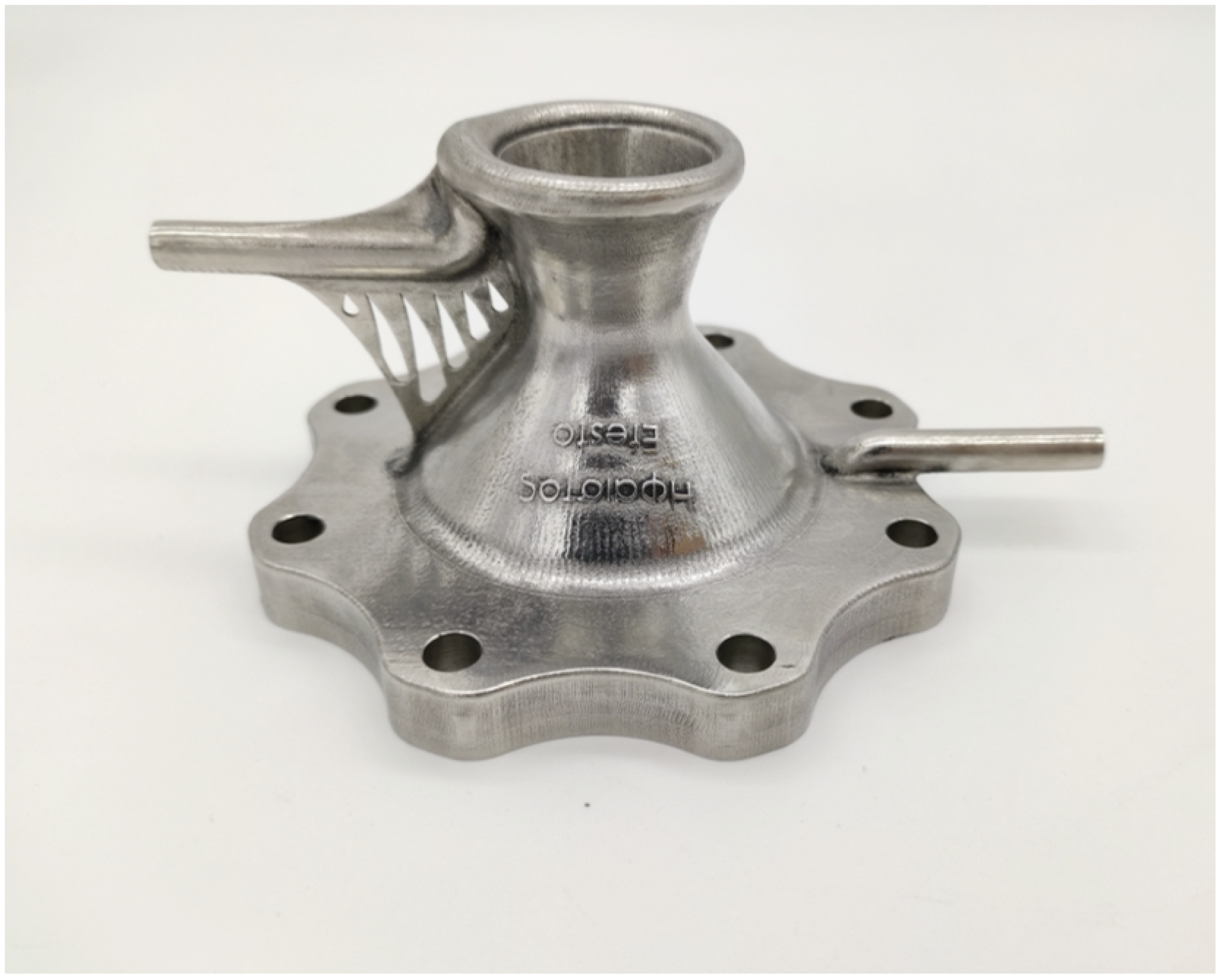
718, which is processed via laser powder-bed fusion additive manufacturing. Such a manufacturing process permits one to realize in a single component the nozzle with integrated inlet and outlet manifolds and feeding lines of the coolant, as well as the mechanical flange for the bolted connection with the combustion chamber. The realized nozzle is shown in Figure 4. It is to be noted that the exposed nozzle surfaces and the feeding line inner surfaces are polished. The major effect of such polishing is the reduction of the surface roughness at the hot-gas side. On the other hand, the roughness of the internal surfaces of the inlet and outlet manifolds and the cooling channels is that typical of the laser powder-bed fusion additive manufacturing process. Cold flow tests of the cooling system, involving flowing ambient temperature water with different mass flow rates, indicate that the average equivalent sand grain roughness in the cooling channels is about 20   μ m.
The nozzle is designed in order to produce about 450 N of thrust when coupled with a combustion chamber operating at a pressure of 11 bar and fed with hydrogen peroxide (having a purity of 91.5 % in weight) and automotive diesel with an oxidizer-to-fuel mass mixture ratio of 6.5 
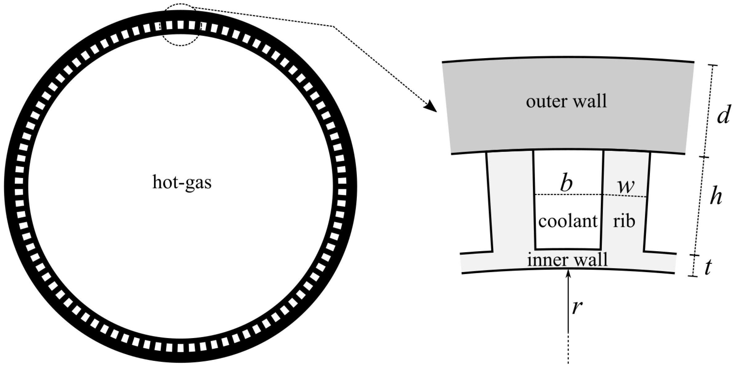
. The axial length of the nozzle is 50 mm and the main hot-gas side geometrical parameters are: a throat diameter D t equal to = 16.57 mm, a subsonic contraction area ratio of 10.77 , and a supersonic expansion area ratio of 2.38 . The inner wall thickness t is equal to 0.8 mm while the outer wall thickness d is equal to 0.95 
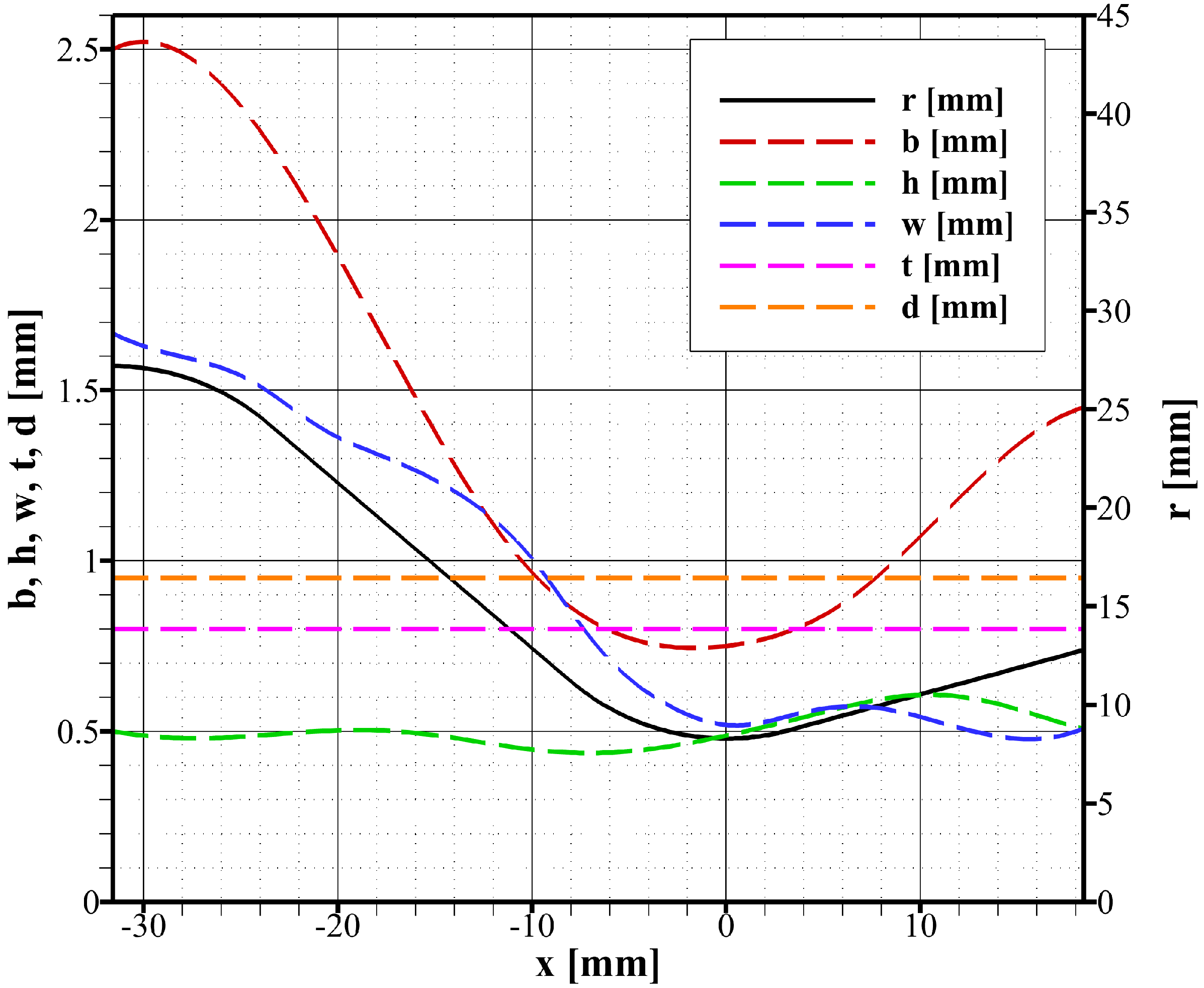
mm. The variation of the geometric parameters r, b, h, w, t, and d along the nozzle axis is shown in Figure 5. The number of cooling channels is 41.

3.2. Experimental Tests

The nozzle is connected to a cylindrical combustion chamber where the hot-gas is produced. Depending on the combustion chamber set-up, whose detailed description can be found in [15], the hot-gas flow can be either decomposed hydrogen peroxide or the combustion products of a mixture of decomposed hydrogen peroxide and automotive diesel. In any case, hydrogen peroxide purity is 91.5 
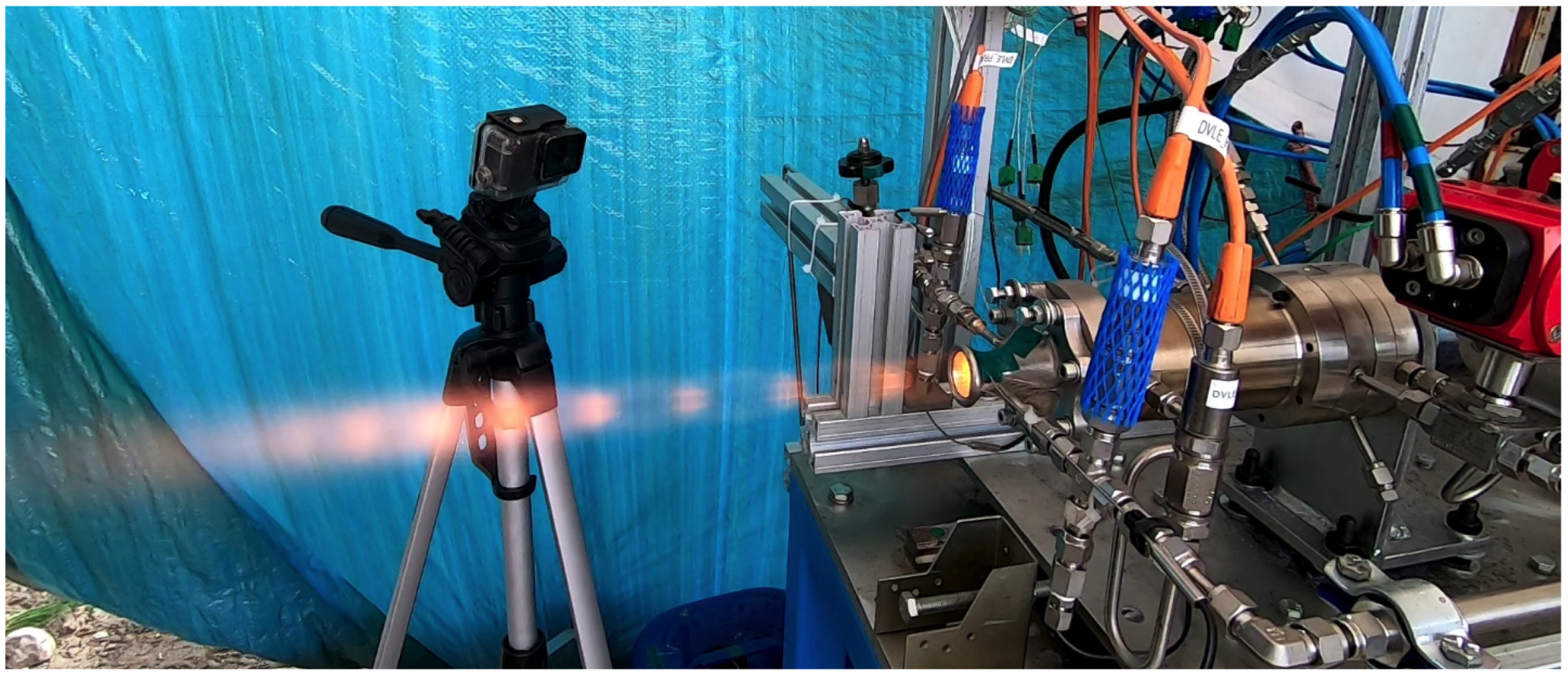
% in weight. In the first case, which can be referred to as mono-propellant configuration, the fuel is not injected and the hydrogen peroxide is decomposed within a suitable catalytic bed reactor that feeds the combustion chamber injection system. In the second case, which can be referred to as bi-propellant configuration, the hydrogen peroxide is decomposed and injected into the combustion chamber as in the previous case, but the suitably atomized liquid fuel is also added. This is done in order to improve the temperature of the hot-gas by virtue of the combustion between the injected propellants. Moreover, in case of bi-propellant configuration the decomposed hydrogen peroxide can be injected either axially or in a swirled mode. Note that although the mono-propellant configuration has also been tested with swirled oxidizer injection, the flow in the nozzle throat was found to be severely blocked due to the proximity of the swirled injector to the nozzle inlet. For this reason, such cases are not considered in this study. The adopted fluid flowing within the cooling system is pressurized distilled water, which is at ambient temperature at the entrance. The coolant flows in counter-flow configuration, that is, in the opposite direction of the hot-gas flow. A photo of a hot-fire test of the bi-propellant configuration with swirled oxidizer injection is shown in Figure 6.
Measured variables that are useful for the present study are the mass flow rate of the propellants and the coolant, the combustion chamber pressure, and the pressure and temperature at the manifolds of the cooling system. The measured experimental data taken during steady-state operation are displayed in Table 1. The reported data include the mass flow rate of the hydrogen peroxide ( m ˙ o x ), the automotive diesel ( m ˙ f u ), and water ( m ˙ c o o l ), the combustion chamber pressure ( p 0 ), the coolant pressure drop ( Δ p c o o l ) and temperature gain ( Δ T c o o l ), and the combustion efficiency ( η c ). The combustion efficiency is evaluated as η c = p 0 A t m ˙ c i d where A t is the nozzle throat area, m ˙ is the propellant mass flow rate ( m ˙ = m ˙ o x + m ˙ f u ) and c i d is the ideal characteristic velocity, which is computed considering a one-dimensional isentropic expansion through the thrust chamber of the hot-gas in chemical equilibrium and considering propellants injected at their actual inlet temperature [10,11].
The results of Table 1 show that a nearly ideal decomposition of hydrogen peroxide is achieved in cases of mono-propellant configuration, as η c is well over 0.9 . On the other hand, the cases with bi-propellant configuration and axial injection result in less complete combustion, as η c is below 0.9 . This is due to unsuitable mixing of the fuel and oxidizer. This was confirmed by a little presence of soot on the nozzle surface, which was removed before each new test by a suitable cleaning treatment. Poor propellant mixing is definitively solved by swirling the oxidizer injection (combustion efficiency of test case 57 is practically ideal). However, since the swirl injector has been damaged, this solution seems to be not feasible. In particular, the visual inspection at the end of test 57 suggested that the cause of the damage is related to the adhesion of the flame to the swirl injector which behaves as a flame holder.

3.3. Calibration of the Heat Transfer Model

The thermal analysis model described in Section 2 is used to reproduce the test cases reported in Table 1. In particular, the coefficient C of the hot-gas heat transfer correlation (13) is calibrated for each test case in order to match the experimental coolant temperature gain Δ T c o o l . This calibration, because Δ T c o o l is an indirect measure of the heat absorbed by the cooling system, ensures that the proposed heat transfer model correctly estimates the total wall heat transfer rate. The correlated coefficient C is shown in Table 2.
The results of Table 2 are quite consistent, especially in the case of bi-propellant configuration. In particular, the coefficient C ranges from about 0.079 to about 0.092 in cases of mono-propellant configuration and from about 0.029 to about 0.030 in cases of bi-propellant configuration. With respect to the average value, in cases of mono-propellant configuration the scattering of the coefficient C is within 9%, while it is less than 2% in cases of bi-propellant configuration. Consequently, considering the average value of the coefficient C, in cases of mono-propellant configuration a reliable hot-gas heat transfer correlation is:
N u = 0.0840 R e 0.8 P r 0.4 ( mono - propellant )
and in cases of bi-propellant configuration a reliable hot-gas heat transfer correlation is:
N u = 0.0296 R e 0.8 P r 0.4 ( bi - propellant )
The robustness of the correlation for the bi-propellant case is noteworthy since it is not affected by the high variability of combustion efficiency related to the different modes of oxidizer injection (axial or swirl). Moreover, the hot-gas correlation (19) is very similar to that found in [9] using more than 100 heat transfer data measured in the throat section of different thrust chambers fed with oxygen and various types of hydrocarbons (mainly, kerosene and methane). In that case, the coefficient C is equal to 0.0310 , which is less than 5% higher than in correlation (19). The difference may be attributable to the different nature of the oxidizer, which is hydrogen peroxide in the present study.
Concerning the relatively high value of the coefficient C in cases of mono-propellant configuration, which is more than three times larger than what found in the literature [9], this can be attributed to different heat transfer mechanisms than pure turbulent convection, as supposed in Section 2.2. In fact, the wall temperature in cases of mono-propellant configuration is so low that water, the main product of hydrogen peroxide decomposition, undergoes a phase change, from vapor away from the wall to liquid in contact with the wall. This phase change is an exothermic phenomenon that contributes to increasing the heat transfer rate at the wall. Consequently, when using a formulation such as (13) for the hot-gas heat transfer correlation, the coefficient C increases because it takes into account both the convection and the phase change.
Apart from the phase change occurring in cases of mono-propellant configuration and not occurring in cases of bi-propellant configuration, a sensitivity study on the coolant heat transfer has been performed in order to better confirm the validity of the achieved results. In fact, the coolant correlation (16) may be affected by a certain uncertainty. To take into account such possible uncertainty, the coolant heat transfer was fictitiously varied from 50 % to + 50 % with respect to correlation (16). The results showed that in any case the calibrated coefficient C of the hot-gas correlation (13) varies by less than 3% in cases of mono-propellant configuration and by less than 2% in cases of bi-propellant configuration. The virtually negligible dependence of hot-gas heat transfer on coolant heat transfer is due to the relatively high thermal resistance offered by the nozzle material, which is the nickel-based alloy Inconel ® 718. In other words, the efficiency of the coolant heat transfer is overset by the thermal resistance of the wall. It is expected that if a copper-based alloy, which has up to 30 times more thermal conductivity than a nickel-based alloy, had been used, this effect would not have occurred. In any case, it is not true that in the case of nickel-based alloy there is no effect of coolant heat transfer. In fact, as will be shown in the next Section 3.4, while the heat flux is practically unaffected by coolant heat transfer, the same is not true for the wall temperature.
Finally, using the physical formulation adopted in [15] and not reported in Section 2 for simplicity, the effect of the hot-gas radiation on the calibration of the coefficient C was studied. The results showed that the effect of radiation is completely negligible. In fact, the calibrated coefficients C reported in Table 2 are virtually unchanged whether or not radiation is taken into account. This is essentially related to the non-excessive combustion temperature, which is about 1000 K in the mono-propellant case and about 2500 K in the bi-propellant case. Obviously, the effect of radiation would be less negligible if more energetic propellants (such as hydrogen-oxygen or methane-oxygen) were used, which can generate a combustion temperature of the order of 3500 K, or propellants that generate a relevant amount of carbonaceous soot under some specific operative conditions (such as oxygen-kerosene) were used.

3.4. Calculation of the Wall Temperature and Heat Flux

To demonstrate the capability of the heat transfer model described in Section 2, the numerical results pertinent to test case 57 (Table 1) are presented. This test case, which is characterized by bi-propellant feeding with swirled oxidizer injection, is selected as it is the most thermally solicited of the whole experimental test campaign. This is the natural consequence of the higher hot-gas temperature resulting from the higher combustion efficiency η c when employing oxidizer swirl injection than when using oxidizer axial injection (Table 1). The hot-gas heat transfer is evaluated with the calibrated correlation (
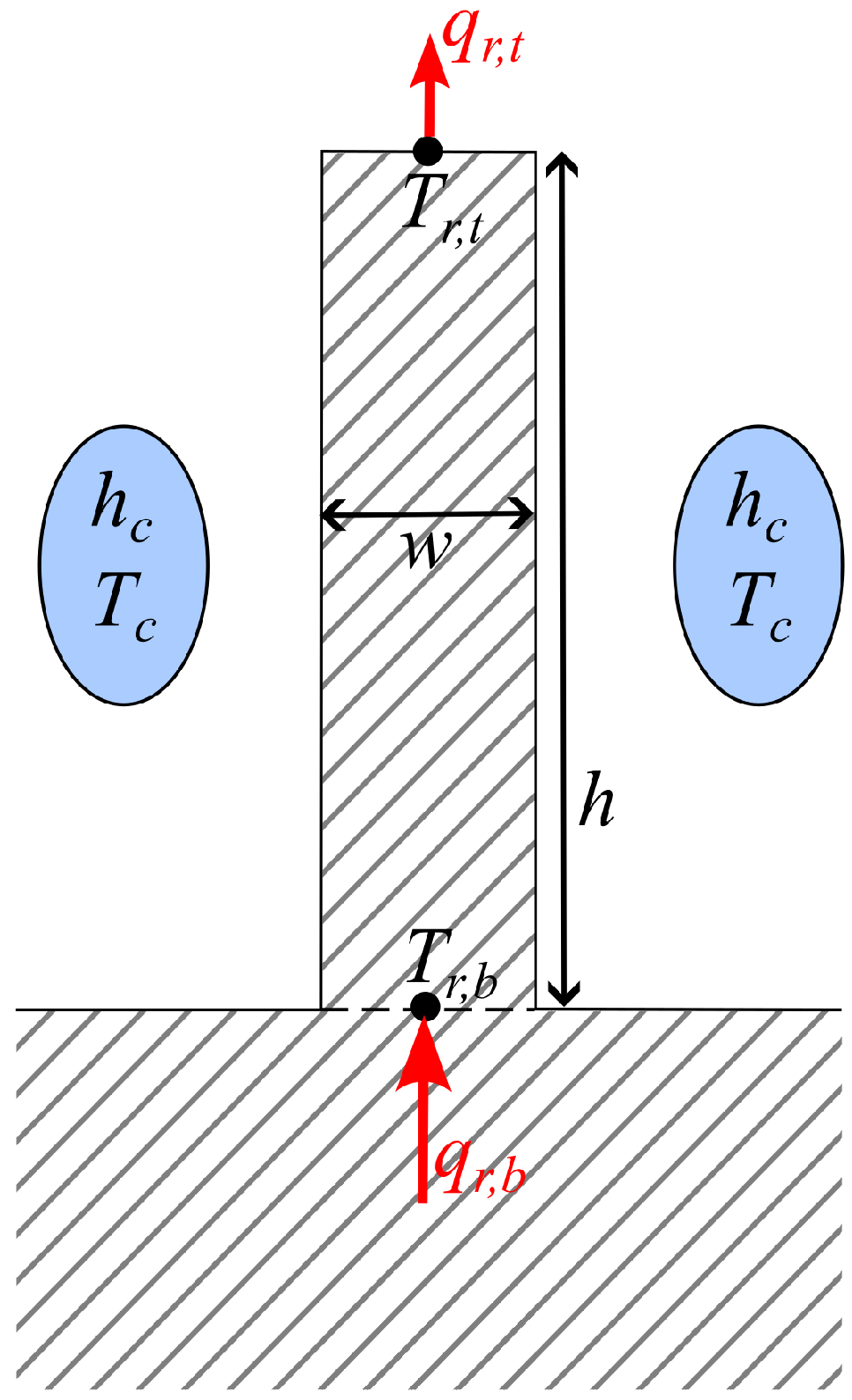
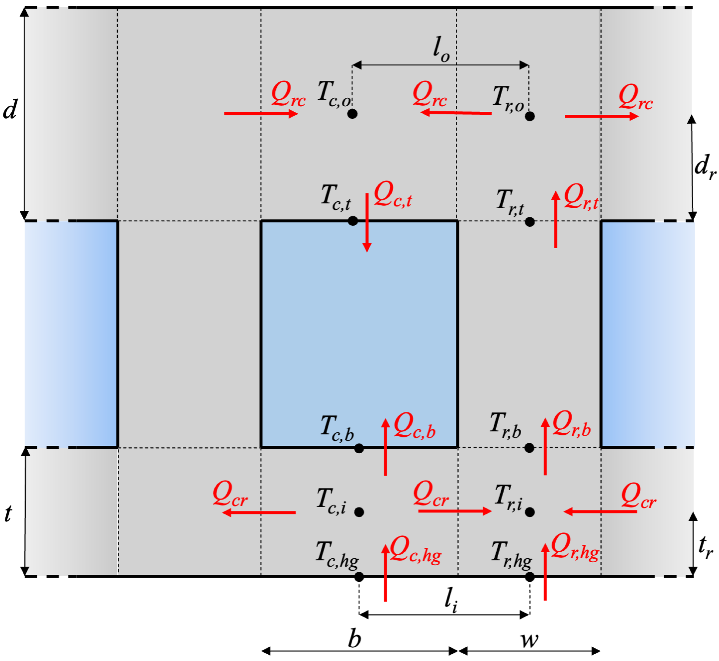
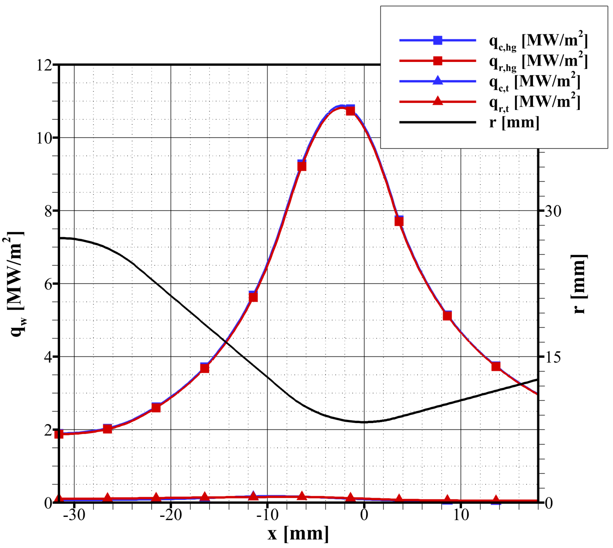
19). Using the symbology adopted in Figure 3, Figure 7 shows the hot-gas side heat fluxes, q c , h g and q r , h g , and the heat fluxes in the outer wall, q c , t and q r , t . The results show that, as expected, the peak heat flux at the hot-gas side occur near the throat. This value is about 11 MW/m 2 . The minimum value is about 2 MW/m 2 , which is attained at the inlet of the convergent ( x = 32 mm). On the other hand, the outer wall is nearly adiabatic as the associated heat fluxes ( q c , t and q r , t ) are always well below 0.2 MW/m 2 . Figure 7 also shows that the heat fluxes in correspondence with the cooling channels are almost equal to those in correspondence with the rib; that is, q c , h g q r , h g and q c , t q r , t . This means that the heat flux is quite evenly distributed along the cross-section.
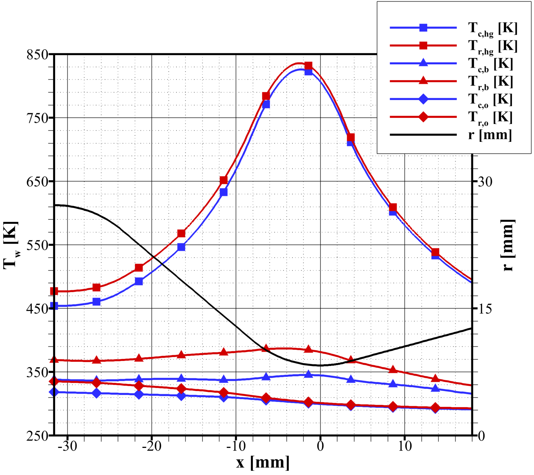
The estimation of the wall temperatures of test case 57 is shown in Figure 8. Differently from the heat fluxes, the wall temperatures in correspondence with the cooling channels (i.e., T c , h g , T c , b , and T c , o that are in blue in Figure 8) are lower than the wall temperatures in correspondence with the ribs (i.e., T r , h g , T r , b , and T r , o that are in red in Figure 8). This is an effect of the better cooling effect of the water flowing in the channels with respect to the rib. At the hot-gas side, the difference among T r , h g and T c , h g is below 20 K, while in correspondence with the cooling channel base the difference among T r , b and T c , b is below 45 K. Figure 8 also highlights that the greater part of the wall temperature gradient is located in the inner wall. For instance, close to the throat, where the wall temperature at the hot-gas side reaches the maximum value of about 835 K, a wall temperature difference T c , h g T c , b of 480 K occurs within a thickness t of 0.8 mm as a result of an entering heat flux of about 11 MW/m 2 (Figure 7).
As anticipated in Section 3.3, the effect of the uncertainty of the coolant heat transfer is almost irrelevant for the evaluation of the heat fluxes shown in 
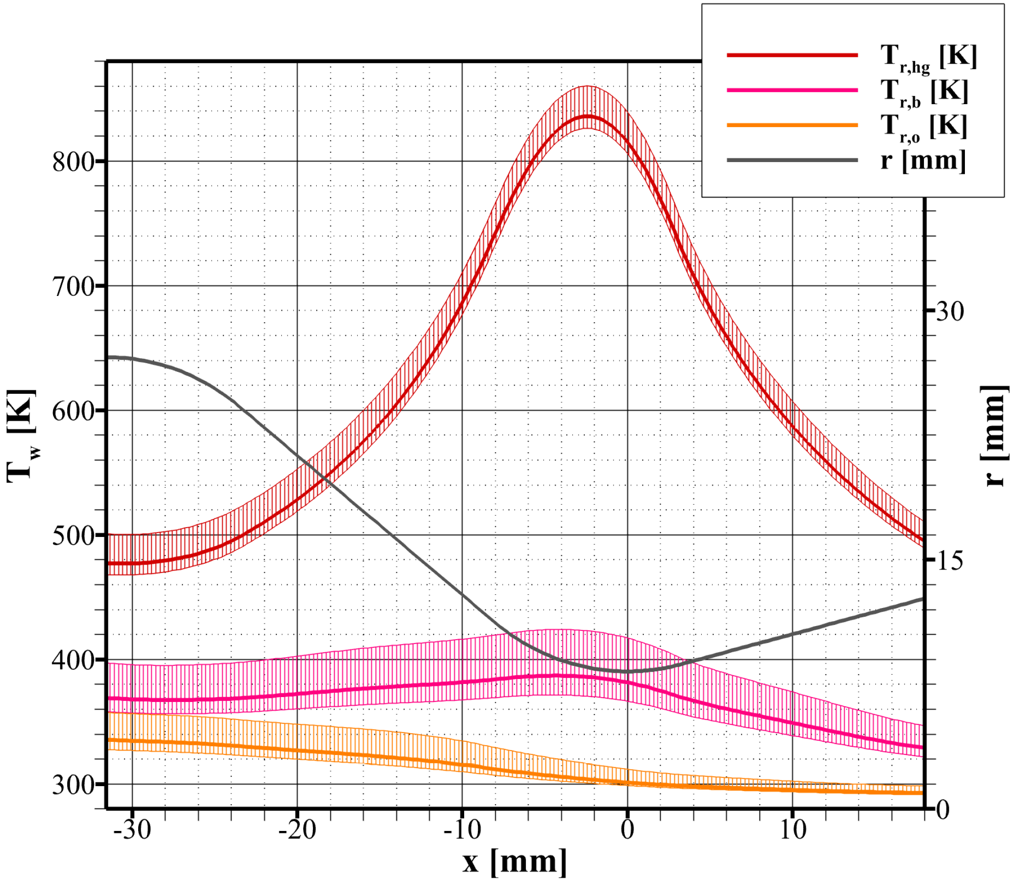
Figure 7 as a result of the relatively high thermal resistance of the adopted material. On the other hand, the uncertainty of the coolant heat transfer has a more marked effect on the wall temperature. This is shown in Figure 9, where the wall temperatures in correspondence with the rib, that is, T r , h g , T r , b , and T r , o , are evaluated considering also an uncertainty of the coolant heat transfer correlation (16) of ± 50 %. It is worth noting that such an uncertainty is rather high as semi-empirical correlations are seldom affected by an uncertainty larger than ± 30 %. Figure 9 shows that the hot-gas side temperature T r , h g increases by about 25 K when the coolant heat transfer is decreased by 50% and decreases by about 10 K when the coolant heat transfer is increased by 50%. The total uncertainty of T r , h g is thus 35 K. This uncertainty of the hot-gas side wall temperature estimation is quite low considering the high uncertainty assumed for the coolant heat transfer. Consequently, the proposed approach, at least for the analyzed nozzle, can be considered fairly reliable for predicting the thermal behavior. Figure 9 shows also that the wall temperature uncertainty increases to 60 K in correspondence with the base of the channel ( T r , b ) and is up to 30 K in the closeout ( T r , o ).

4. Conclusions

In this study, a simplified steady-state thermal analysis model for regeneratively cooled rocket engine thrust chambers is presented. This model, relying on semi-empirical models for the hot-gas and coolant convective heat transfer, is characterized by an original multi-zone discretization for the wall conduction that makes it possible to take into account the multi-dimensional nature of this problem. In particular, considering both radial and circular heat conduction within the wall permits one to estimate the different temperatures in correspondence with the cooling channels and the ribs. The proposed model has been used to reproduce the experimental data taken from an additively manufactured water-cooled nozzle that is connected to a combustion chamber either fed with decomposed hydrogen peroxide (mono-propellant configuration) or decomposed hydrogen peroxide and automotive diesel (bi-propellant configuration). The thrust chamber (i.e., combustion chamber and nozzle) is designed to produce about 450 N when operating with a chamber pressure of 11 bar. The hot-gas heat transfer has been calibrated with respect to the total heat transfer rate entering the coolant water. Because of the very possible condensation at the wall of the decomposition products in cases of mono-propellant configurations, two distinct hot-gas heat transfer correlations have been found for the two configurations. In any case, thanks to the relatively low thermal conductivity of the nickel-based alloy adopted for the nozzle, the selected correlations permit one to predict total wall heat transfer rate very accurately. This does not guarantee that the wall heat flux, which is a local quantity that varies along the nozzle length, is reproduced with equal accuracy as the total wall heat transfer rate. However, the heat flux distribution is typically fairly well reproduced by the adopted correlation for turbulent hot-gas flow, which is characterized by a Nusselt number proportional to the Reynolds number to a power of 0.8 . The coolant heat transfer, on the other hand, cannot be calibrated with the adopted experimental apparatus. Hence, the effect of the uncertainty of the adopted coolant heat transfer correlation was evaluated considering its possible deviation of ± 50 %. The resulting wall temperature is predicted with an uncertainty of a few tens of kelvins. This level of accuracy can be considered more than suitable for the design and thermal analysis of similar thrust chambers.

Author Contributions

Conceptualization, M.P.; data curation, M.F., M.S., F.B. and M.P.; formal analysis, M.F. and M.P.; investigations, M.F., M.S., F.B. and M.P.; methodology, M.F. and M.P.; resources, M.F., M.S. and F.B.; software, M.F.; supervision, M.S. and F.B.; validation, M.F. and M.P.; visualization, M.P.; writing—original draft preparation, M.P.; writing—review and editing, M.F., M.S. and F.B. All authors have read and agreed to the published version of the manuscript.

Funding

This research received no external funding.

Data Availability Statement

Not applicable.

Acknowledgments

The authors thank the graduating student Riccardo Cantiani for having contributed to the extension of the numerical code for two-dimensional study.

Conflicts of Interest

The authors declare no conflict of interest.

References

  1. Song, J.; Sun, B. Coupled numerical simulation of combustion and regenerative cooling in LOX/methane rocket engines. Appl. Therm. Eng. 2016, 106, 762–773. [Google Scholar] [CrossRef]
  2. Daimon, Y.; Negishi, H.; Kawashima, H. Film cooling performance analysis of a full-scale liquid rocket engine combustion chamber based on a coupled combustion and heat transfer simulation. In Proceedings of the 53rd AIAA/SAE/ASEE Joint Propulsion Conference, Atlanta, GA, USA, 10–12 July 2017. AIAA Paper 2017-4919. [Google Scholar]
  3. Rahn, D.; Haidn, O.; Riedmann, H. Conjugate heat transfer simulation of a subscale rocket thrust chamber using a timescale based frozen non-adiabatic flamelet combustion model. In Proceedings of the AIAA Propulsion and Energy 2019 Forum, Indianapolis, IN, USA, 19–22 August 2019. AIAA Paper 2019-3864. [Google Scholar]
  4. Perakis, N.; Preis, L.; Haidn, O.J. Wall heat flux evaluation in regeneratively cooled rocket thrust chambers. J. Thermophys. Heat Transf. 2021, 35, 127–141. [Google Scholar] [CrossRef]
  5. Fröhlich, A.; Popp, M.; Schmidt, G.; Thelemann, D. Heat transfer characteristic of H2/O2-combustion chambers. In Proceedings of the 29th AIAA/ASME/SAE/ASEE Joint Propulsion Conference, Monterey, CA, USA, 28–30 June 1993. AIAA Paper 1993-1826. [Google Scholar]
  6. Sichler, E.L.; Montes, J.D.; Chandler, F.O. One-dimensional thermal steady state analysis and procedure for a low pressure liquid oxygen and liquid methane rocket engine. In Proceedings of the 2018 Joint Propulsion Conference, Cincinnati, OH, USA, 9–11 July 2018. AIAA Paper 2018-4602. [Google Scholar]
  7. Song, J.; Liang, T.; Li, Q.; Cheng, P.; Zhang, D.; Cui, P.; Sun, J. Study on the heat transfer characteristics of regenerative cooling for LOX/LCH4 variable thrust rocket engine. Case Stud. Therm. Eng. 2021, 28, 101664. [Google Scholar] [CrossRef]
  8. Incropera, F.P. Fundamentals of Heat and Mass Transfer; Wiley: Hoboken, NJ, USA, 2007. [Google Scholar]
  9. Pizzarelli, M. Overview and analysis of the experimentally measured throat heat transfer in liquid rocket engine thrust chambers. Acta Astronaut. 2021, 184, 46–58. [Google Scholar] [CrossRef]
  10. Gordon, S.; McBride, B.J. Computer Program for Calculation of Complex Chemical Equilibrium Compositions and Applications, I. Analysis; National Aeronautics and Space Administration, Lewis Research Center: Cleveland, OH, USA, 1994; NASA-RP 1311. [Google Scholar]
  11. McBride, B.J.; Gordon, S. Computer Program for Calculation of Complex Chemical Equilibrium Compositions and Applications, II. User’s Manual and Program Description; National Aeronautics and Space Administration, Lewis Research Center: Cleveland, OH, USA, 1996; NASA-RP 1311. [Google Scholar]
  12. Dipprey, D.F.; Saberski, R.H. Heat and momentum transfer in smooth and rough tubes at various Prandtl numbers. Int. J. Heat Mass Transf. 1963, 6, 329–353. [Google Scholar] [CrossRef]
  13. NIST, National Institute of Standards and Technology, 2023. Available online: http://webbook.nist.gov/chemistry/fluid/ (accessed on 15 March 2023).
  14. Santi, M.; Fagherazzi, M.; Barato, F.; Pavarin, D. Design and testing of a hydrogen peroxide bipropellant thruster. In Proceedings of the AIAA Propulsion and Energy 2020 Forum, Virtual, 24–28 August 2020. AIAA Paper 2020-3827. [Google Scholar]
  15. Fagherazzi, M.; Santi, M.; Barato, F.; Pavarin, D. Design and testing of a 3D printed regenerative cooled nozzle for a hydrogen peroxide based bi-propellant thruster. In Proceedings of the AIAA Propulsion and Energy 2021 Forum, Virtual, 9–11 August 2021. AIAA Paper 2021-3235. [Google Scholar]
Figure 1. Schematic of a cross-section of a regeneratively cooled thrust chamber. Note that the cooling-channel dimensions refer to a section that is orthogonal to the coolant flow.
Aerospace 10 00403 g001
Figure 2. Schematic of a cooling fin of height h and base w (the third dimension can be considered much larger than h and w).
Aerospace 10 00403 g002
Figure 3. Schematic of a cooling channel with relevant wall temperatures and heat transfer rates (the symbol Q indicates the heat transfer per unit length of the chamber). Note that the dimensions refer to a section that is orthogonal to the coolant flow.
Aerospace 10 00403 g003
Figure 4. The regeneratively cooled nozzle with integrated mechanical flange to the combustion chamber and inlet and outlet coolant manifolds with associated feeding lines. The nozzle is made in Inconel ® 718 via the laser powder-bed fusion additive manufacturing process.
Aerospace 10 00403 g004
Figure 5. Geometric parameters of the cooling channels along the nozzle axis: nozzle radius r, channel base b, channel height h, rib thickness w, inner wall thickness t, and outer wall thickness d. The throat is located at x = 0 . The hot-gas flows from left to right.
Aerospace 10 00403 g005
Figure 6. Photo of the hot-fire test 57 (bi-propellant configuration with swirled oxidizer injection).
Aerospace 10 00403 g006
Figure 7. Prediction of the wall heat fluxes along the nozzle axis for test case 57.
Aerospace 10 00403 g007
Figure 8. Prediction of the wall temperatures along the nozzle axis for test case 57.
Aerospace 10 00403 g008
Figure 9. Prediction of the wall temperatures along the nozzle axis for test case 57 considering an uncertainty of the coolant heat transfer correlation (16) of ± 50 %.
Aerospace 10 00403 g009
Table 1. Experimental tests results.
TestConfigurationOxidizer m ˙ ox m ˙ fu m ˙ cool p 0 Δ p cool Δ T cool η c
ID.Injection(g/s)(g/s)(g/s)(bar)(bar)(K)
47mono-propellantaxial12601345.274.8610.80.94
48mono-propellantaxial12702085.2811.567.760.94
49mono-propellantaxial14501456.055.7310.910.95
50mono-propellantaxial14502136.1212.908.160.96
55bi-propellantaxial13019.32279.5813.7915.00.87
56bi-propellantaxial13019.31399.615.0124.970.87
57bi-propellantswirl13019.722411.013.7324.810.99
58bi-propellantaxial13019.51379.715.0925.430.88
Table 2. Calibration of the hot-gas heat transfer correlation N u = C R e 0.8 P r 0.4 .
Test IDConfigurationOxidizer InjectionC
47mono-propellantaxial0.0794
48mono-propellantaxial0.0919
49mono-propellantaxial0.0803
50mono-propellantaxial0.0844
55bi-propellantaxial0.0295
56bi-propellantaxial0.0301
57bi-propellantswirl0.0294
58bi-propellantaxial0.0293
Disclaimer/Publisher’s Note: The statements, opinions and data contained in all publications are solely those of the individual author(s) and contributor(s) and not of MDPI and/or the editor(s). MDPI and/or the editor(s) disclaim responsibility for any injury to people or property resulting from any ideas, methods, instructions or products referred to in the content.

