Article

Swirl Flow and Heat Transfer in a Rotor-Stator Cavity with Consideration of the Inlet Seal Thermal Deformation Effect

1
School of Energy and Power Engineering, Beihang University, Beijing 100191, China
2
Research Institute of Aero-Engine, Beihang University, Beijing 100191, China
3
Hunan Aviation Powerplant Research Institute, Aero Engine Corporation of China (AECC), Zhuzhou 412002, China
*
Author to whom correspondence should be addressed.
Aerospace 2023, 10(2), 134; https://doi.org/10.3390/aerospace10020134
Submission received: 26 December 2022 / Revised: 26 January 2023 / Accepted: 28 January 2023 / Published: 31 January 2023
(This article belongs to the Special Issue Fluid-Dynamics and Heat Transfer in Aerospace Propulsion Systems)

Abstract

:
In the typical structure of a turboshaft aero-engine, the mass flow of the cooling air in the rotor-stator cavity is controlled by the inlet seal labyrinth. This study focused on the swirl flow and heat transfer characteristics in a rotor-stator cavity with considerations of the inlet seal thermal deformation effect. A numerical framework was established by integrating conjugate heat transfer (CHT) analysis and structural finite element method (FEM) analysis to clarify the two-way aero-thermo-elasto coupling interaction among elastic deformation, leakage flow, and heat transfer. Simulation results showed that the actual hot-running clearance was non-uniform along the axial direction due to the temperature gradient and inconsistent structural stiffness. Compared with the cold-built clearance (CC), the minimum tip clearance of the actual non-uniform hot-running clearance (ANHC) was reduced by 37–40%, which caused an increase of swirl ratio at the labyrinth outlet by 5.3–6.9%, a reduction of the Nusselt number by up to 69%. The nominal uniform hot-running clearance (NUHC) was defined as the average labyrinth tip clearance. The Nusselt number of the rotating disk under the ANHC was up to 81% smaller than that under the NUHC. Finally, a clearance compensation method was proposed to increase the coolant flow and decrease the metal temperature.

1. Introduction

The secondary air system (SAS) is essential for aero-engines moving toward a higher thermally efficient economy [1] and operation safety [2]. As an important part of the SAS, rotor-stator cavities provide cooling air from the compressor to different turbine components, either for cooling or sealing [3]. Heat transfer in the rotor-stator cavity has a significant influence on the safety of gas turbine disks, which are engine-life-limited parts (ELLP) in compliance with the requirement of FAR33.70. The fracture of a gas turbine disk could directly induce non-containment of high-energy debris, resulting in catastrophic events like loss of aircraft and human life [4]. Thus, a deep understanding of the flow structure and heat transfer characteristics in rotor-stator cavities is significant for disk cooling optimization and the reliable operation of aero-engines, which has been the subject of a large number of recent studies.
Extensive research has shown that swirl flow in the rotor-stator cavity is one of the major features that affect heat transfer and windage characteristics. Swirl flow in the rotor-stator cavity, determining the relative tangential velocity between the fluid and rotating disk surface, plays an important role in the velocity distribution of the boundary layer. The shear stress caused by the velocity gradient can generate frictional drag and heat the cooling air, which increases the power input for overcoming windage and the coolant air for necessary cooling requirements [5]. For the swirl flow characteristics, valuable publications from different perspectives (swirl ratio, windage heating, and moment coefficient) have been conducted by experimental investigation and numerical simulation. Fernando et al. [6] investigated the effect of surface roughness on swirl flow with the Large Eddy Simulation (LES) method, illustrating that tangential velocity profiles in the rotor-stator cavity are sensitive to even a little roughness level on the rotor surface alone. Quan et al. [7] revealed the effect of ultrahigh rotational speed on the tangential flow and heat transfer in a millimeter-scale rotor-stator cavity. Ren et al. [8] employed the particle image velocimetry (PIV) technique for velocity measurements in the rotor-stator cavity and showed swirl ratio distributions under different rotational Reynolds numbers and non-dimensional mass flow rates. Zhang et al. [9] compared the axial distribution of tangential velocity under different cooling airflow rates. Zhao et al. [10] investigated the influence of blade fracture on the distribution of the swirl ratio in the rotor-stator cavity. Tao et al. [4] experimentally and numerically studied windage heating in a shrouded rotor-stator cavity with the superimposed flow. Moghaddam et al. [11] conducted Computational fluid dynamics (CFD) predictions of the swirl flow in a rotor–stator cavity with a superimposed radial flow and investigated the effect on the moment coefficient and velocity distributions of different rotating bolt numbers. Kuntze et al. [12] adopted two measuring procedures to obtain the friction torque and compared the moment coefficients for two procedures at different rotational Reynolds numbers and gap ratios. The importance of swirl flow has been widely recognized by scholars from different perspectives.
For the heat transfer characteristics, a large number of investigations focused on the heat transfer coefficient (HTC) and temperature distribution. Zhang et al. [13] reported the effect of the mass flow rate and the rotation speed on the heat transfer of the pre-swirl rotor–stator cavity. Luo et al. [14,15,16] conducted experimental research on heat transfer of rotor-stator cavities and pointed out that the dimensionless mass flow rate of cooling air is one of the key factors affecting the Nusselt number of the rotating disk. Karabay et al. [17] investigated the effect of the swirl ratio of the cooling air on heat transfer in the rotating cavity and confirmed an optimal swirl ratio to minimize the Nusselt number. Liao et al. [18,19] found the pressure ratio and rotational Reynolds number exerted an influence on the magnitude of the HTC, and the local Nusselt number could be correlated with the local rotational Reynolds number by a power law. Liao et al. [20] also numerically investigated heat transfer characteristics in the rotor-stator cavity using steady-state flow analysis, conjugate CFD, and the fully coupled finite element method (FEM)/CFD. The distributions of temperature and the HTC predicted by the three solvers were compared. Volkov [21] conducted a conjugate heat transfer (CHT) analysis in a rotor-stator cavity, and temperature distributions of the rotor and stator surfaces were presented. Jia et al. [22] also used the CHT method to solve for the heat transfer in a rotor-stator cavity, and the temperature rise in the turbine disk was studied. In the field of heat transfer in the rotor-stator cavity, the necessity and the applicability of the CHT method have been confirmed by many scholars.
Although a series of research has been conducted to investigate swirl flow and heat transfer in the rotor-stator cavity with significant achievements, most studies do not discuss the influence of the upstream components owing to the simplified modeling. In the typical structure of a turboshaft aero-engine, the mass flow of the cooling air in the rotor-stator cavity is controlled by the inlet labyrinth seal. Structural analysis indicated that the labyrinth seal clearance is the most susceptible component to external loads. Up to 15% of the average standard deviation is found to be due to the thermal and centrifugal load [23]. Thus, the effect of inlet seal thermal deformation should not be neglected, especially for the high-temperature turbine disk cavity. Many scholars [24,25,26,27] have confirmed that the labyrinth clearance would experience dynamic change with combined centrifugal and thermal loads [28], even producing non-uniform deformation along the axial direction [29] during engine operation. Additionally, the change in the labyrinth clearance has a direct impact on the leakage flow [30,31], outlet swirl [32,33], and total temperature rise caused by windage heating [26,34], which all have a non-negligible influence on the heat transfer in downstream rotor-stator cavities. However, there is still a lack of in-depth and comprehensive evaluation of the effect of inlet seal thermal deformation on the heat transfer in rotor-stator cavities.
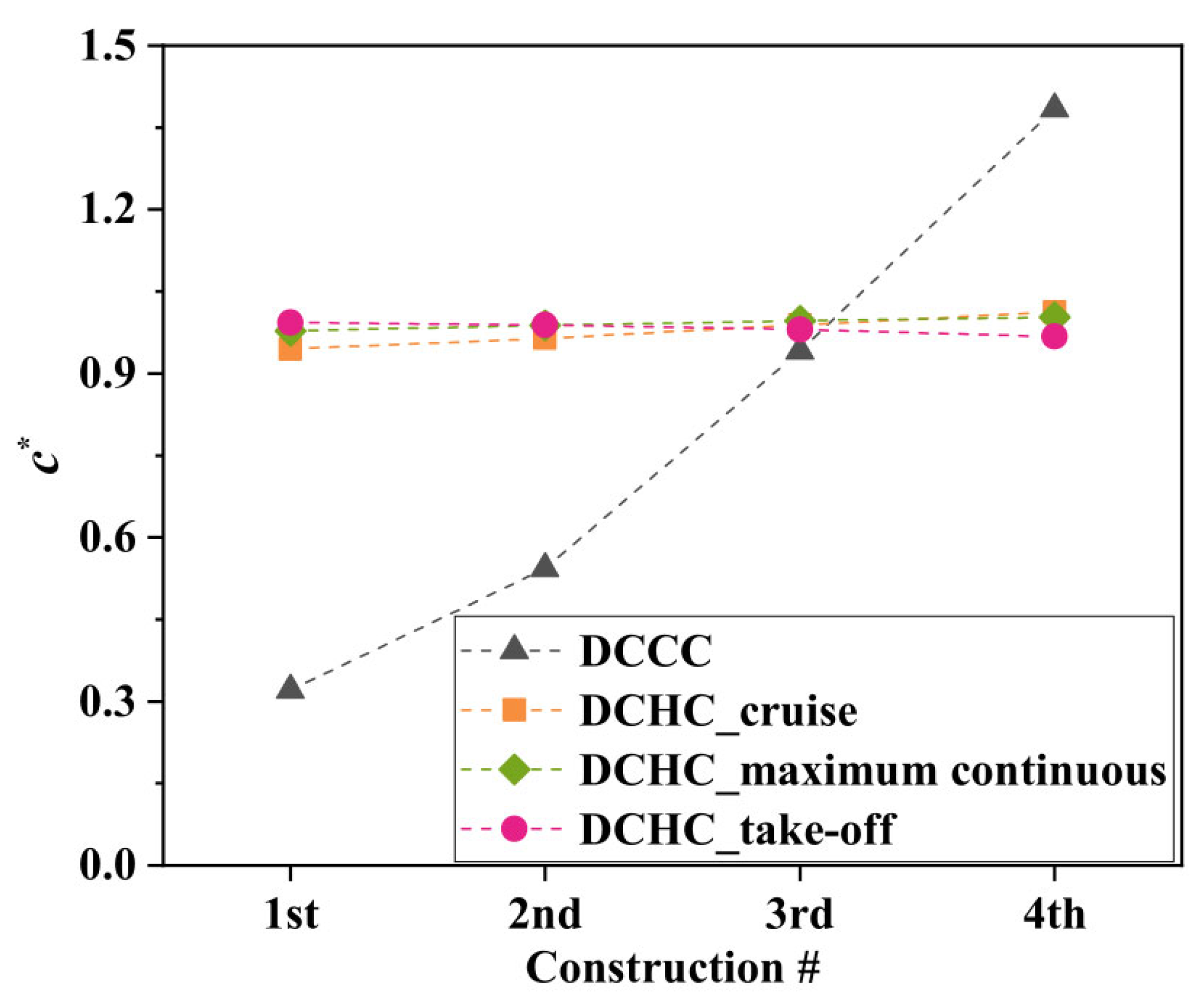
The contribution and novelty of the current research focus on two primary features: (1) the non-uniform hot-running profile of the inlet labyrinth was found, and its effect on swirl flow and heat transfer in the rotor-stator cavity is first discussed; (2) a clearance compensation method is proposed and validated to weaken the adverse effects caused by the non-uniformity thermal deformation of the seal clearance.
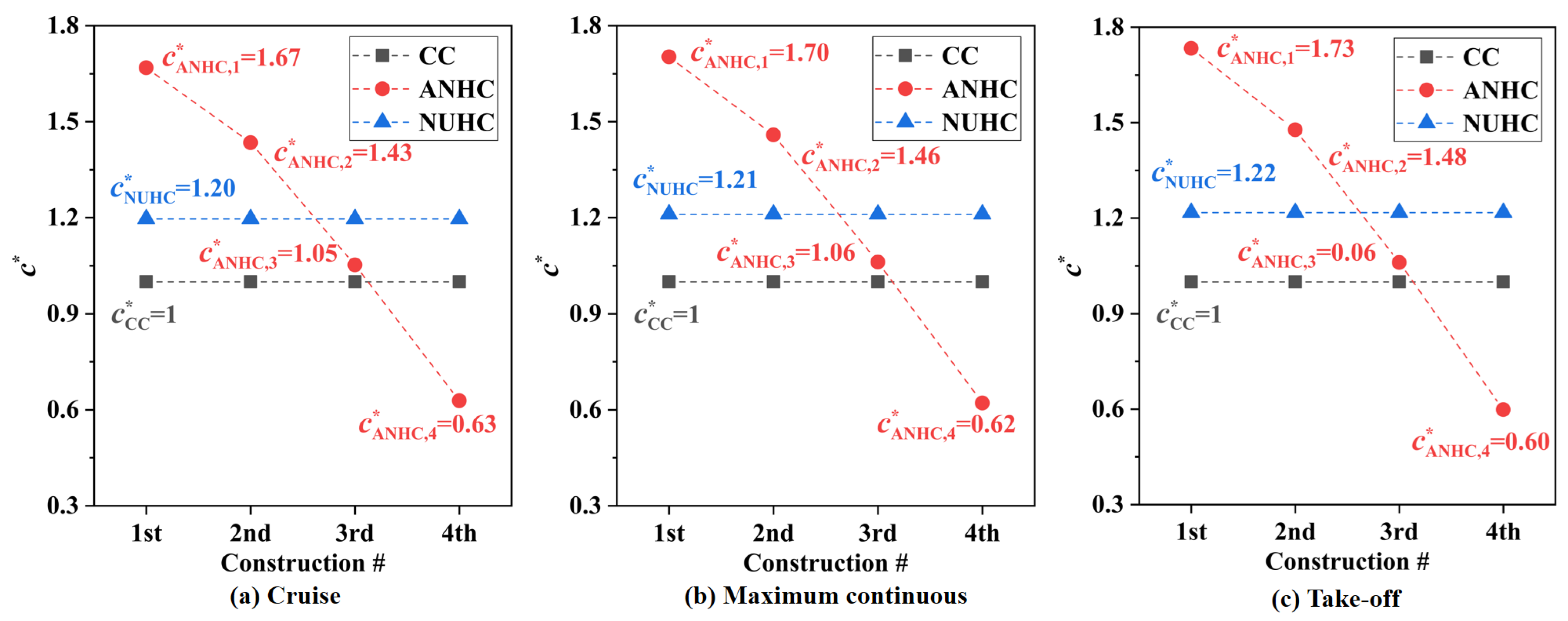
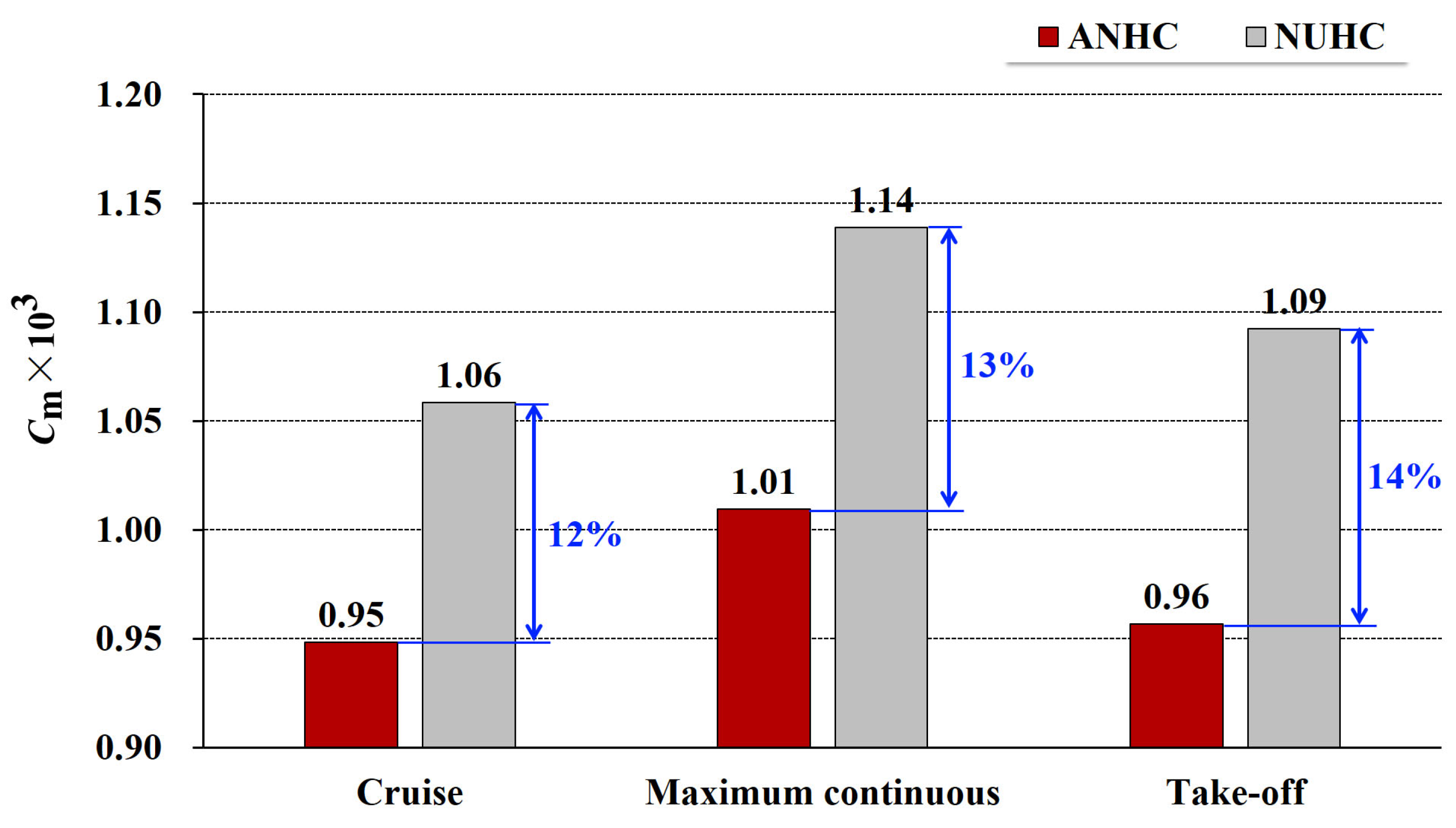
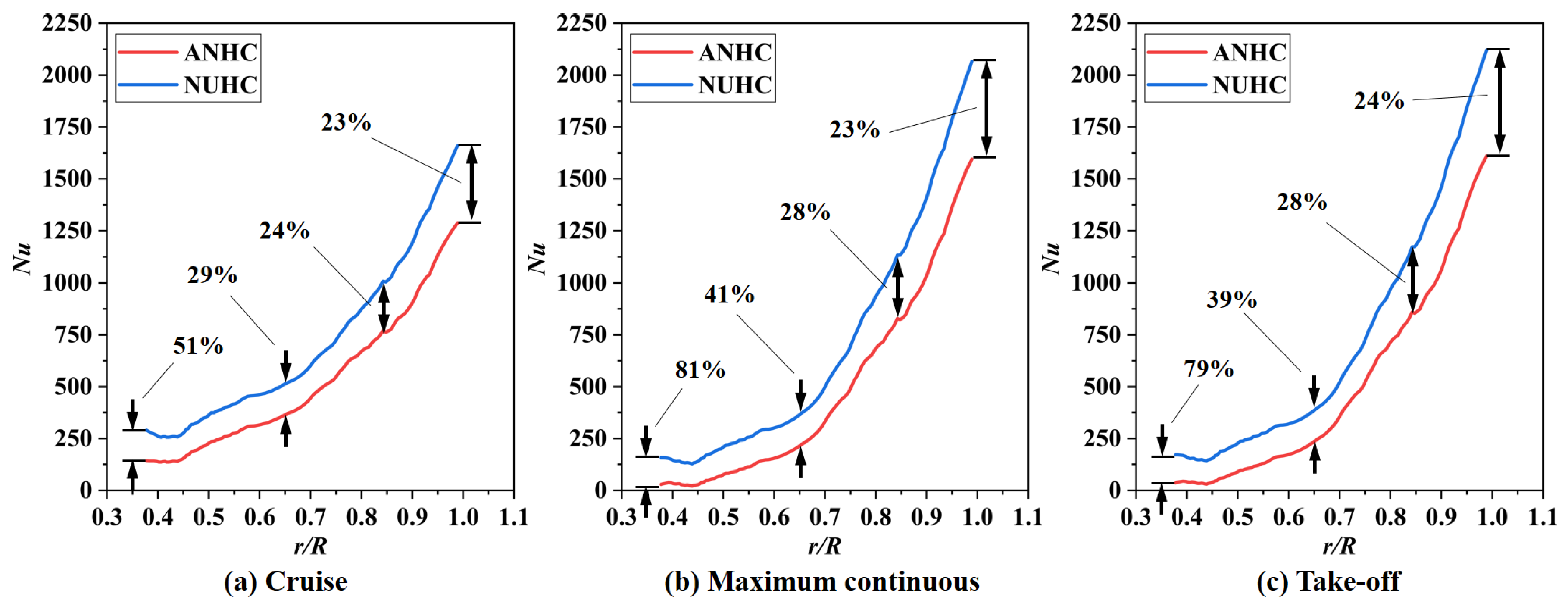
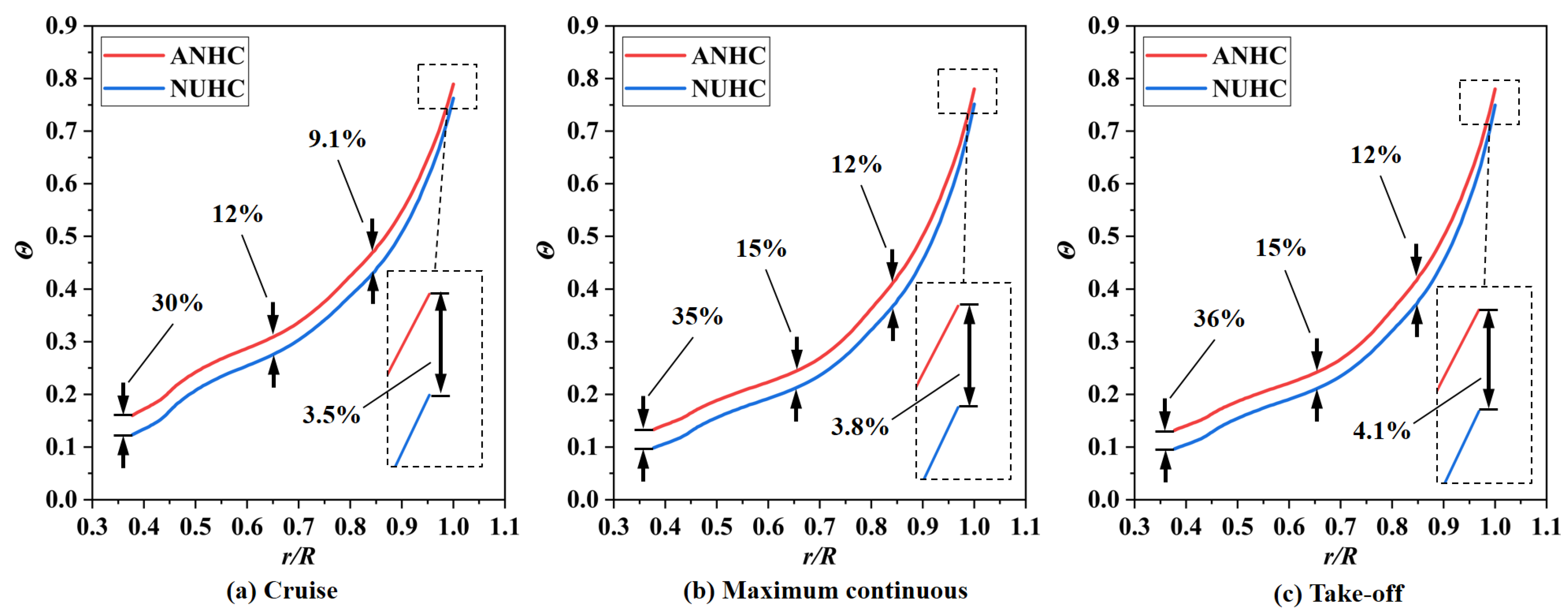
In this paper, a numerical framework was established by integrating CHT analysis and structural FEM analysis, considering two-way aero-thermo-elasto coupling interaction among elastic deformation (affecting seal clearance), leakage flow (affecting HTC of the disk), and heat transfer (affecting solid temperature). A comparison of the flow structure, swirl flow, and heat transfer under the cold-built clearance (CC) and the actual non-uniform hot-running clearance (ANHC) was conducted. To highlight the influence of non-uniformity of the labyrinth clearance, the nominal uniform hot-running clearance (NUHC) was defined as the arithmetic mean of tip clearances and also compared against the ANHC. Finally, a clearance compensation method was proposed and validated to weaken the adverse effects caused by the non-uniformity of the seal clearance. The present investigation establishes the foundation for subsequent engineering applications for the safety design of the aero-engine SAS.

2. Methodology and Modeling

2.1. System Configuration and the Simplified Model

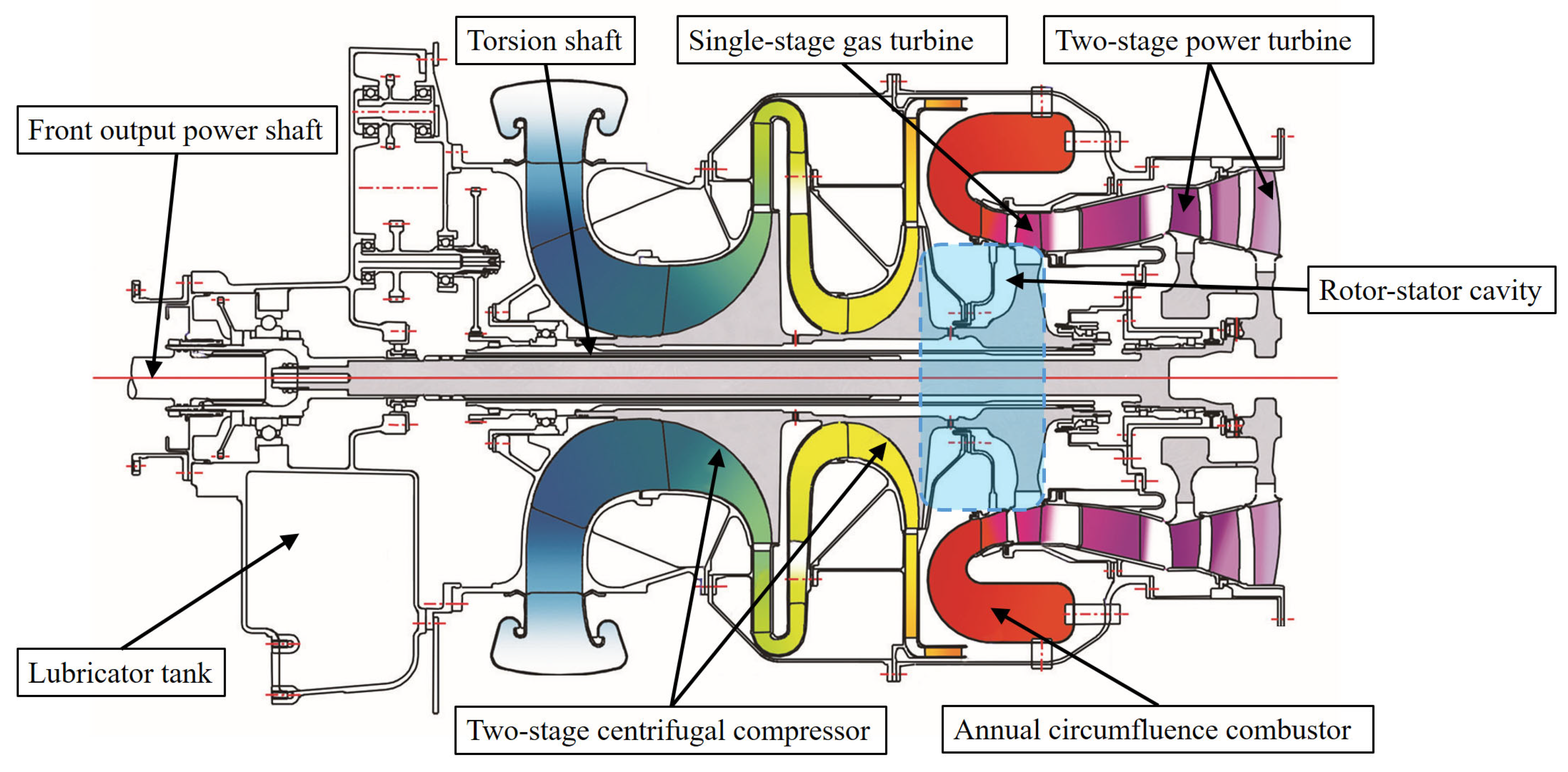
This study aimed at the swirl flow and heat transfer characteristics of the rotor-stator cavity in consideration of the thermal deformation of the inlet labyrinth seal. In the typical structure of turboshaft engines, as shown in Figure 1 [35], a labyrinth is installed between the outlet of the centrifugal compressor disk cavity and the inlet of the turbine disk cavity. The labyrinth is situated below the circumfluence combustor, metering the mass flow rate of the cooling air from the compressor outlet to the turbine disk cavity, which is used to cool the turbine disk and prevent gas from invading the disk cavity. However, the labyrinth seal at the inlet of the rotor-stator cavity experiences harsh thermal loads, which would lead to thermal deformation of the labyrinth seal and result in heat transfer degradation in the rotor-stator cavity.
To facilitate this study, the structure of the turbine disk cavity and inlet labyrinth seal was simplified as follows:
(a)
The influence of the compressor diffuser and the turbine guide vane was ignored, and only the thin-wall construction between the compressor disk and the turbine disk was analyzed, which is the main factor in the thermal deformation of the inlet labyrinth seal.
(b)
Gas turbine blades were ignored, and an equivalent centrifugal load was adopted to the turbine disk rim.
(c)
The supporting function of the coupling sleeve teeth and bearings was simplified to a simple displacement constraint.
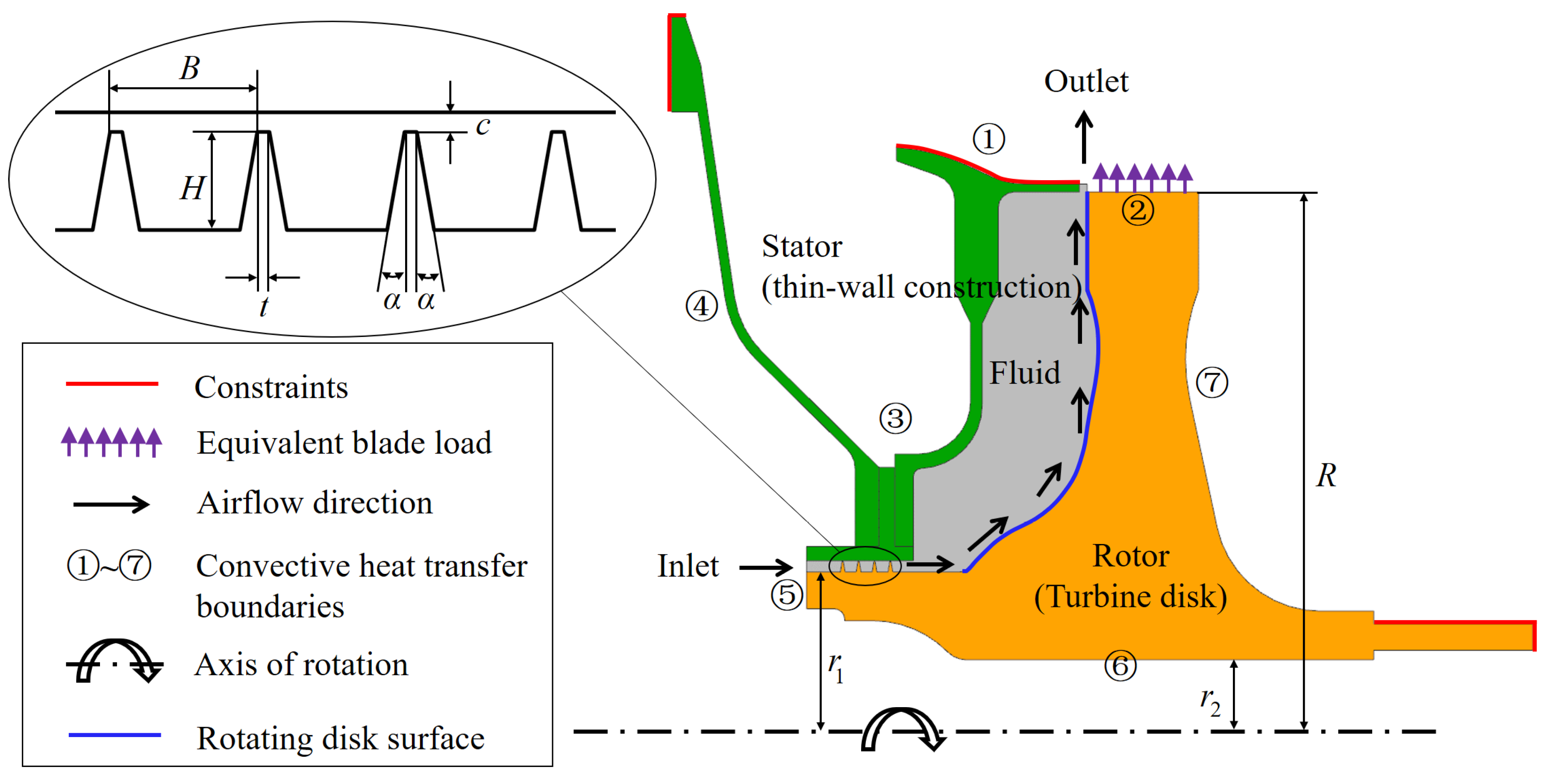
The simplified computational domain of the rotor-stator cavity and inlet labyrinth seal is illustrated in Figure 2. As can be seen in Figure 2, the green part, the orange part, and the gray part are the stationary assembly, the rotating assembly, and the fluid domain, respectively. The main geometric parameters are specified in Table 1. As a general design experience, it is recommended that the seal clearance be 0.15–0.3% of its radius [36]. In the current study, the labyrinth was located at the inlet of the turbine disk cavity, which is a hot component, so the upper value of the recommended seal clearance (0.3%) was adopted.

2.2. Governing Equations

The governing equations included Navier-Stokes equations for the fluid domain and thermoelastic equations for the solid domain.
For the fluid domain, Navier-Stokes equations are shown as Equations (1)–(3).
ρ f τ + · ρ V   =   0
ρ f τ + · V V   =   ρ f f p + · μ f V + V T 2 3 μ f · V
ρ f τ + · V c p T   =   ρ f Q + · k f T + Φ + τ + · V p
In the above equations, V is the velocity vector, f is the body force, Q is the heating rate of internal heat source, and Φ is the dissipation function.
For the solid domain, thermoelastic equations are shown as Equations (4)–(6).
τ ρ s J   =   0
Δ u + 1 1 2 ν e + ρ s μ f 2 1 + ν 1 2 ν α Δ T   =   ρ s μ 2 u τ 2
· k s T   =   ρ s c T τ + 3 λ + 2 μ α T e τ + ρ s Q
In the above equations, J is the Jacobi determinant of coordinate transformation, u is the displacement vector, e = · u is the volume strain, ν is Poisson’s ratio, α is thermal expansion coefficient, and λ , μ are Lame constants.
For fluid-solid interface, force and energy balance equations are shown as Equations (7)–(9).
η s τ   =   η f τ
λ e + μ ( u + u T )   =   f n
h T w T 0   =   k f T η n | η n   =   η s
η s and η f are position vectors at the solid boundary and the fluid boundary respectively, η n is the external normal direction of the fluid-solid interface, and f n is the force vector of the fluid on the solid.
In this investigation, the body force of the air was ignored, and there was no internal heat source in the computing domain. The steady-state simulation (time-dependent analysis) was carried out numerically, so the time derivative terms in the above equations are all zero. In Equation (6), 3 λ + 2 μ α T e / τ is the coupling term of the thermoelastic equation, reflecting the temperature change caused by elastic deformation. The thermoelastic coupling term of the turbine disk is a tiny amount compared to the heat transfer term, so the thermoelastic coupling effect was ignored in the solution process.

2.3. Numerical Method

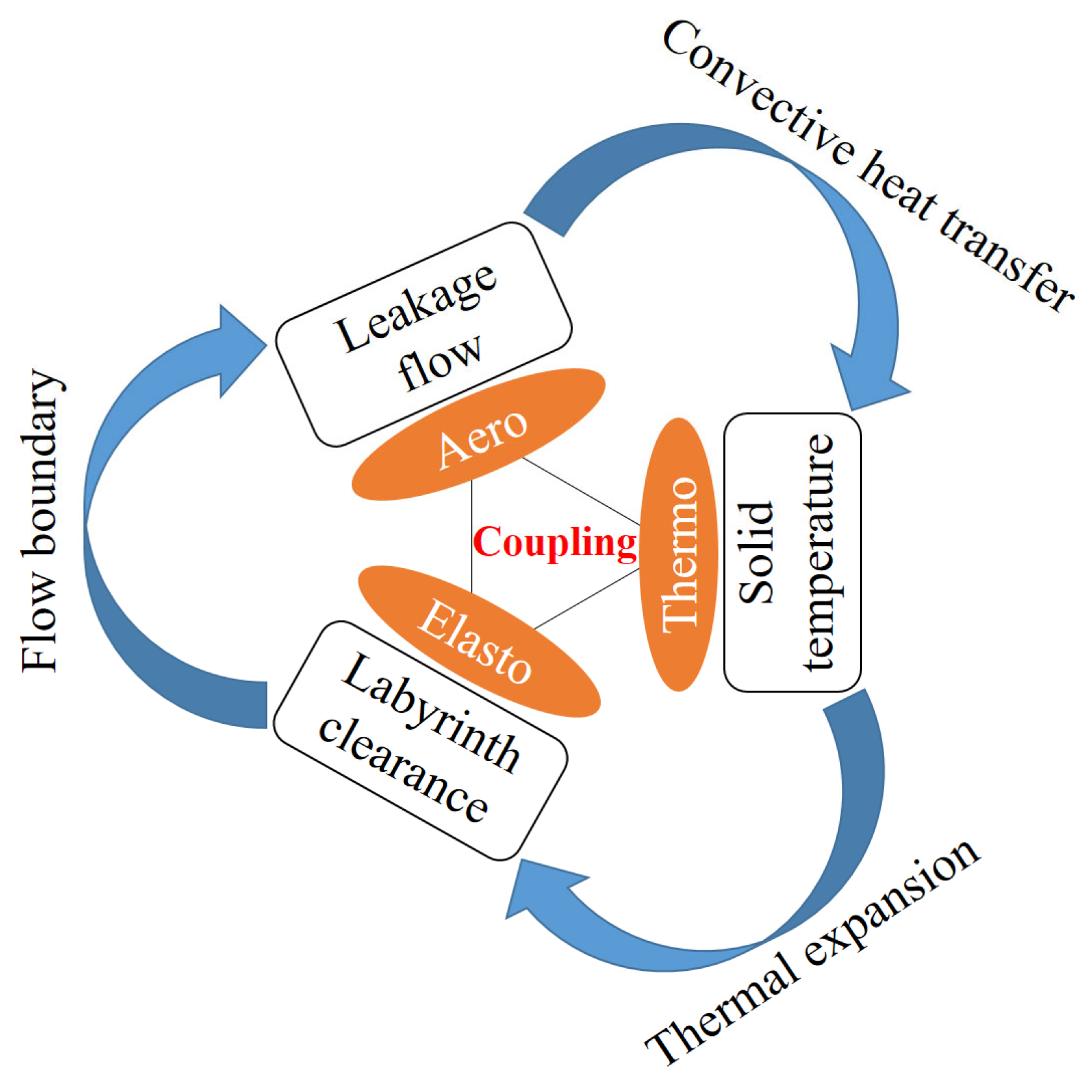
For the rotor-stator cavity and inlet labyrinth seal, there is a complex multi-physics coupling relationship among the labyrinth leakage flow, heat transfer in the disk cavity, solid conduction, and structural deformation, as shown in 
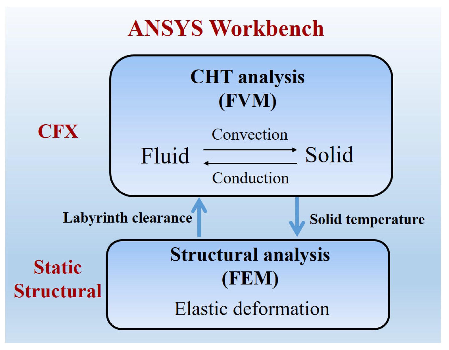
Figure 3. The labyrinth clearance is the flow boundary of leakage flow, which determines the mass flow rate, total temperature, and swirl ratio of cooling air in the disk cavity, thereby affecting the convective heat transfer of the turbine disk. The distribution of the solid temperature field is closely related to the heat transfer of the turbine disk, which will cause thermo-elastic deformation of the structure, and in turn, affect the labyrinth clearance. In order to accurately solve the two-way aero-thermo-elasto coupling relationship among leakage flow, convective heat transfer, solid heat conduction, and structural deformation, a computational strategy was developed by integrating conjugate heat transfer (CHT) analysis and structural finite element method (FEM) analysis under the platform of ANSYS Workbench (a commercial software), as shown in Figure 4. The CFX module simultaneously solves fluid convective heat transfer and solid heat conduction by finite volume method (FVM), realizing CHT analysis. The fluid field in the rotor-stator cavity and the temperature field of the rotor and the stator were evaluated by considering fluid-solid interaction. Moreover, the Static Structural module solves the structural elastic deformation by FEM, realizing structural deformation analysis. The radial displacements of the rotor and stator and, consequently, the new seal clearance profile were evaluated by considering the temperature distribution and the centrifugal load. The simulation was a non-linear analysis because the physical properties of the fluid and the solid are temperature dependent. The fluid was regarded as ideal air, which is a compressible fluid. The dynamic viscosity and thermal conductivity of the fluid were subject to the Sutherland formula in Appendix A. The effects of temperature on the thermal and mechanical properties of solid materials are considered in Appendix B.
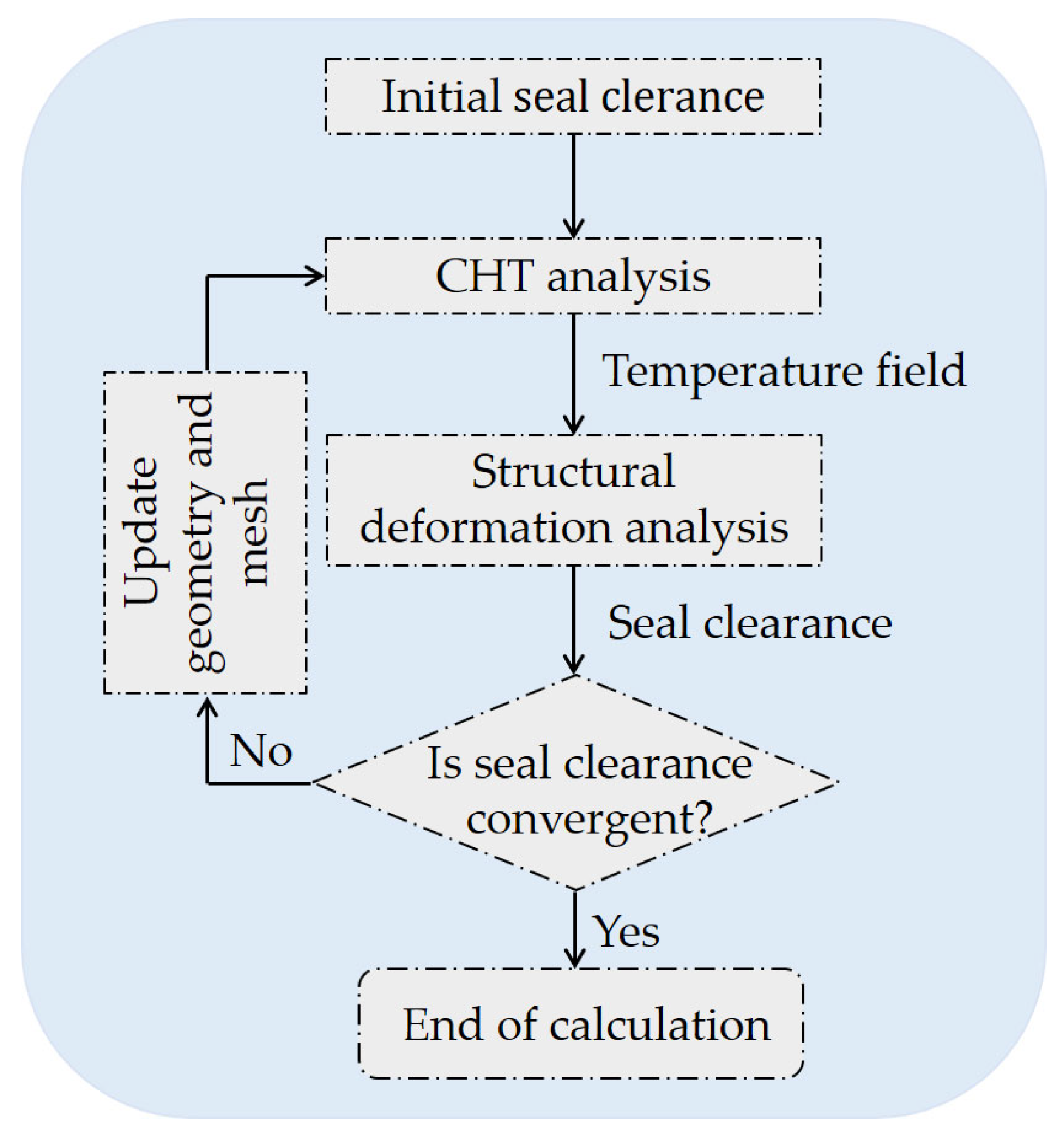
The solution process is shown in Figure 5. Solid temperature and labyrinth clearance were transferred between the two modules, and the solution was iteratively solved until the solution converged in terms of seal clearance. The seal clearance convergence criterion was the clearance difference between the two adjacent iterations and shall not exceed ±5 μm. Firstly, the labyrinth clearance was estimated, and the CHT analysis was carried out under the initial clearance. Then the solid temperature field was transferred to the FEM solver for structural deformation analysis. Finally, the calculated seal clearance was compared with the initial clearance. If the convergence criterion was satisfied, the calculation stopped; otherwise, the geometry and mesh were updated according to the new seal clearance, and then the next iteration cycle began.
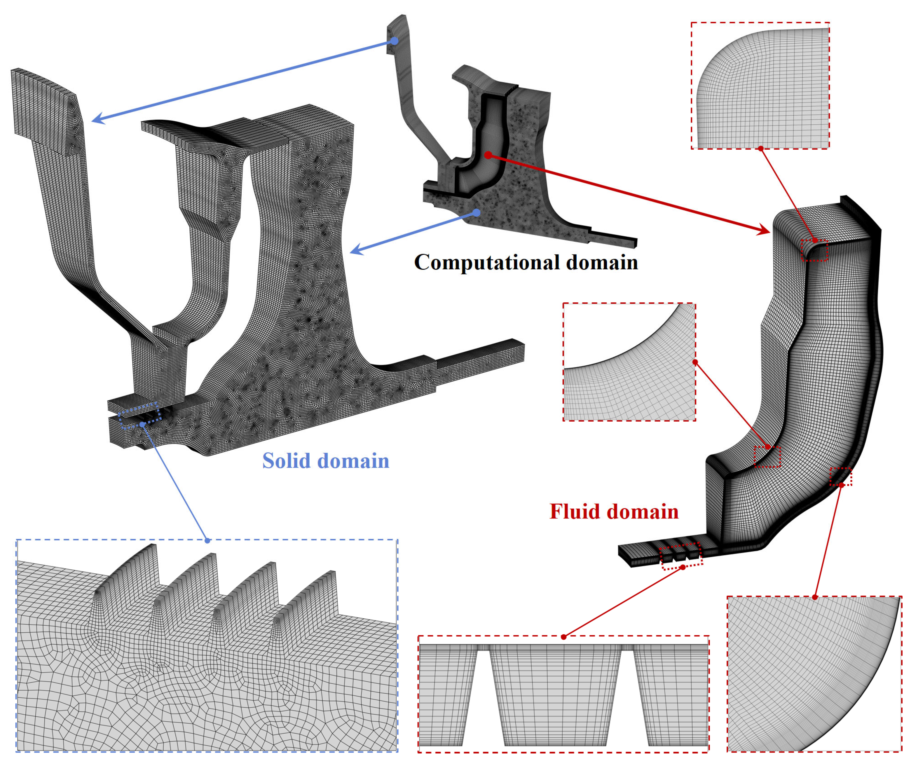
Figure 6 shows the computational grids of the solid domain and fluid domain. Hexahedral grids were generated for the fluid domain, while hexahedral and triangular prism hybrid grids were adopted for the solid domain. For the sake of completely taking into account the inlet seal thermal deformation effect, the mesh was refined specifically for the labyrinth seal to capture the temperature gradient and radial displacement variation of the labyrinth seal. Mesh refinement near the wall was carried out to ensure that y+ was approximately 1, which was suitable for the Shear Stress Transport (SST) turbulence model. Taking into account axis symmetry, a 10° periodic sector model (1/36 sector) was selected in both the CHT and FEM analyses to reduce the time cost of the aero-thermo-elasto coupling calculation. In the CHT analysis session, a rotational periodicity interface model was performed for the periodic symmetry planes. The upwind scheme was used to discretize the turbulence terms, and the convection term was discretized by the high-resolution scheme. The air was regarded as a compressible fluid, and the total energy method was selected to simulate heat transfer. In the FEM analysis, the periodical symmetrical constraints were assigned for the circumferential symmetry planes. Other constraints were set in the specific location, as depicted in Figure 2. A specific angular velocity, Ω, was loaded to the rotating disk, which was defined by the rotational Reynolds number Re ω . The materials of the rotor and stator were two kinds of high-temperature Ni-based superalloy. Appendix B shows the thermal expansion coefficient, elastic modulus, and Poisson’s ratio of the solid materials in detail.

2.4. Dimensionless Parameters and Boundary Conditions

In order to improve the generality of the results, the boundary parameters and main operation parameters involved in this paper were subjected to dimensionless processing as follows. Radial structural deformation ( Δ r ) and labyrinth clearance (c) were normalized by the cold-built labyrinth clearance ( c 0 ):
Δ r *   =   Δ r c 0
c *   =   c c 0
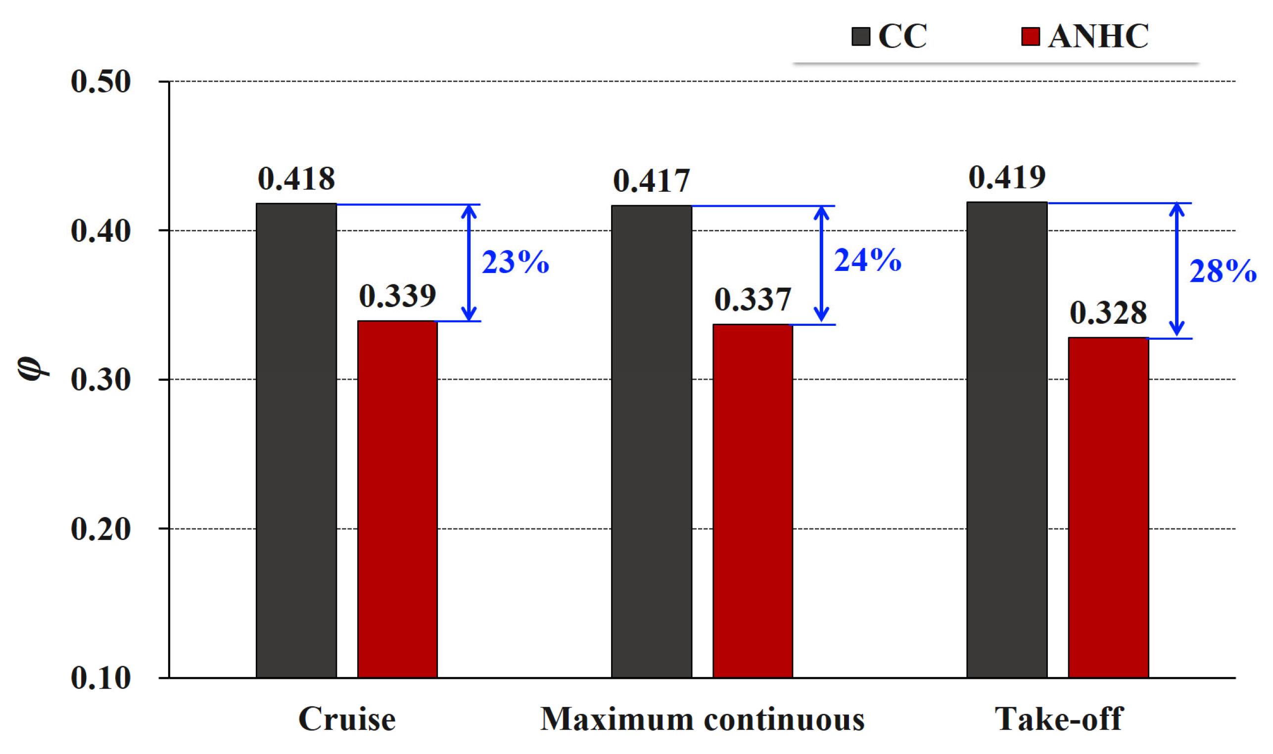
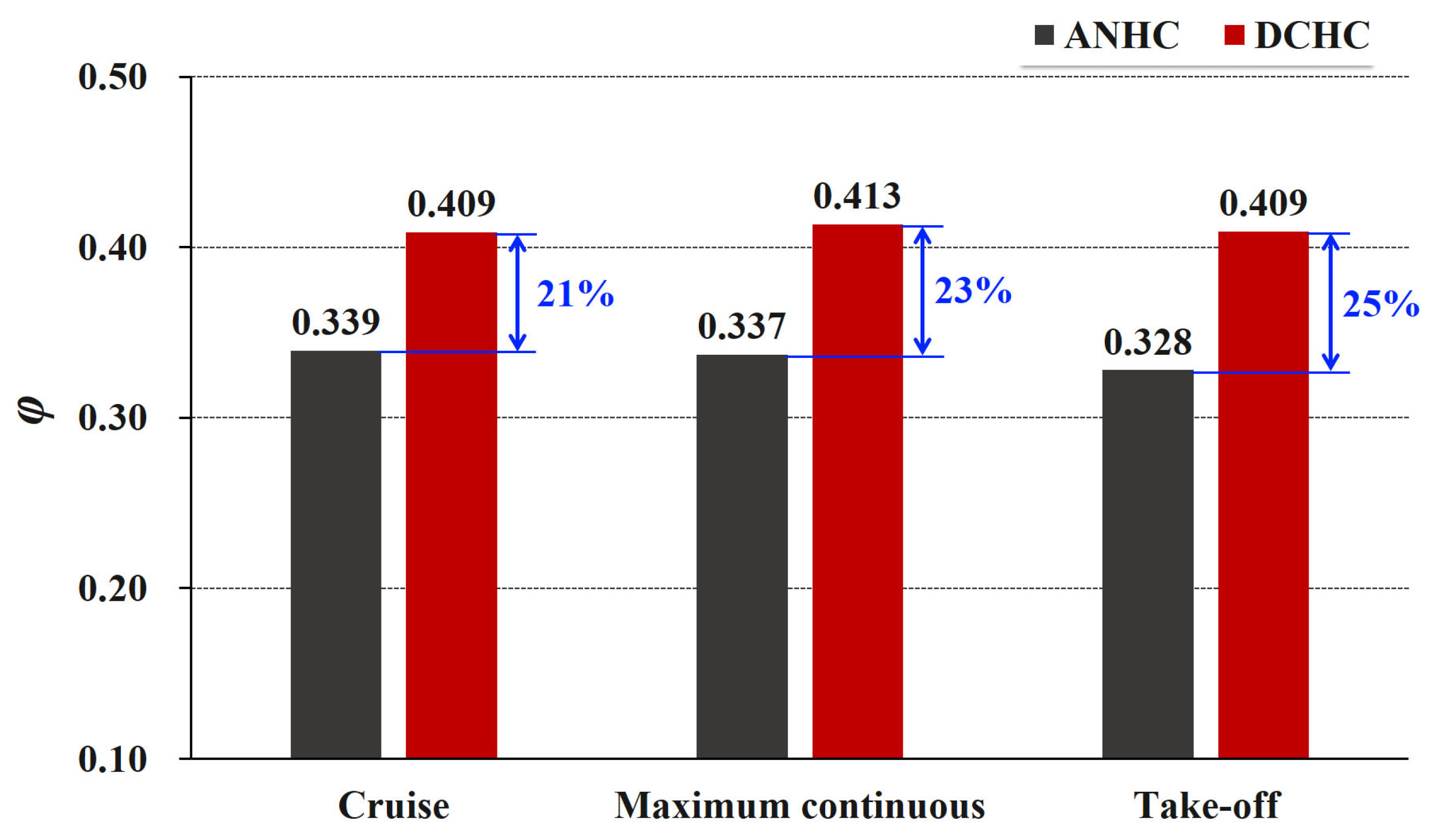
As for the fluid flow, the mass flow rate of through-flow cooling air ( m ˙ 
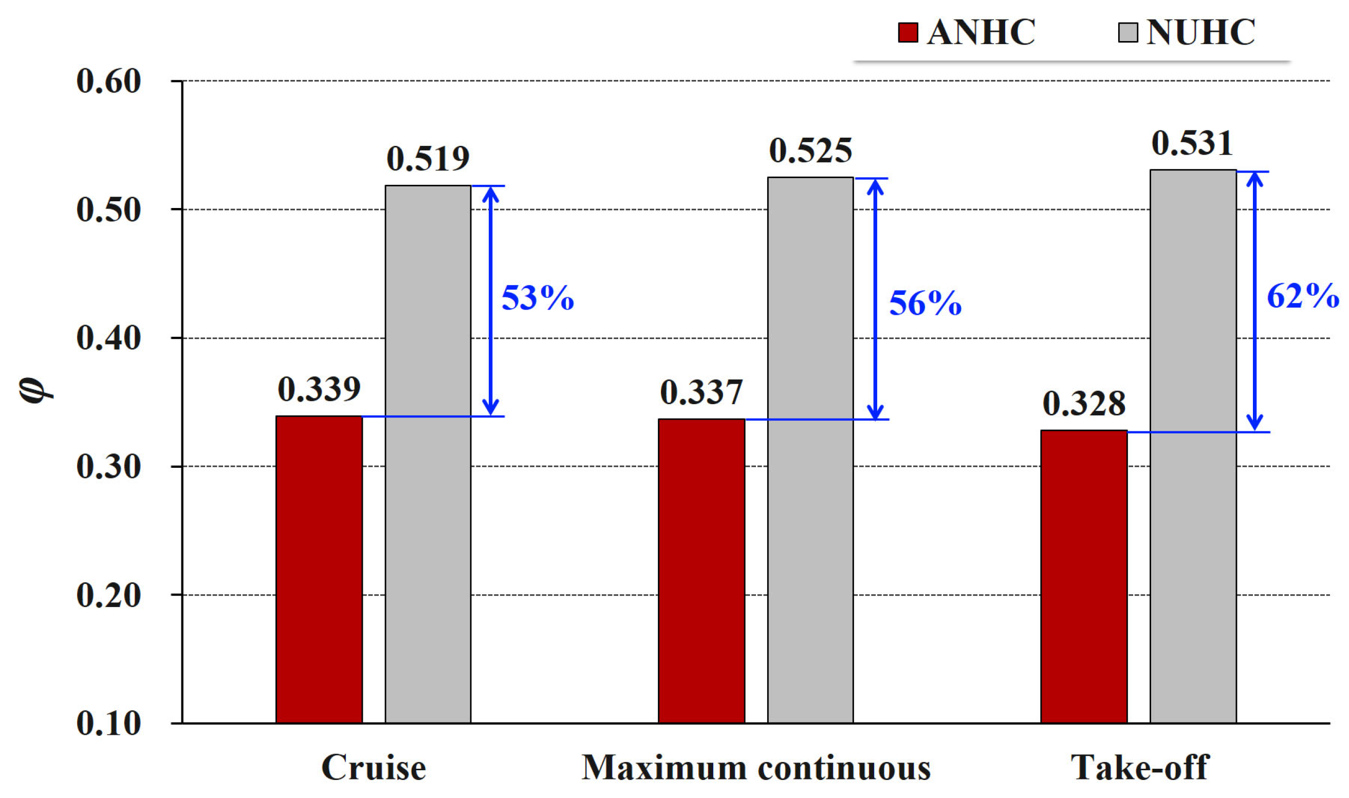
) was expressed by the flow coefficient, which is defined as:
φ   =   m ˙ ( RT t , in ) 1 / 2 A 0 p t , in
where R is the gas constant, 287 J/(kg·K) for the air, and A 0 is the area of the cold-built seal clearance.
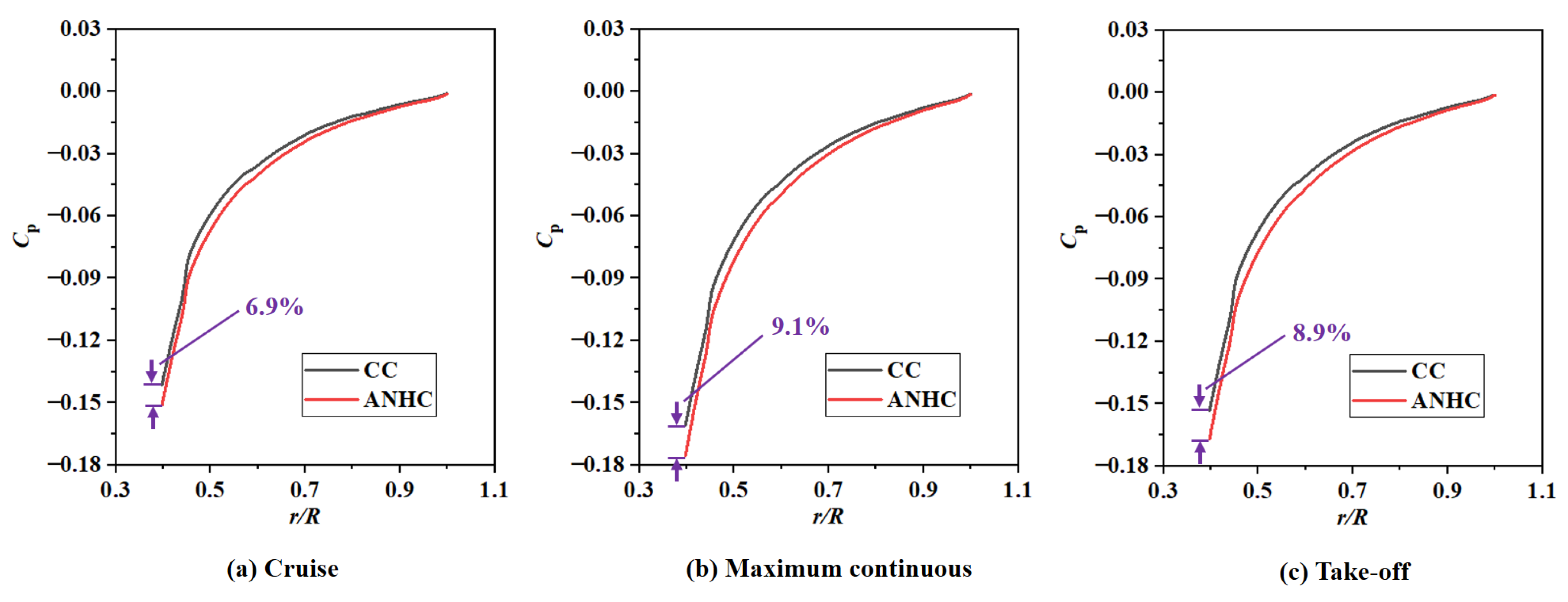
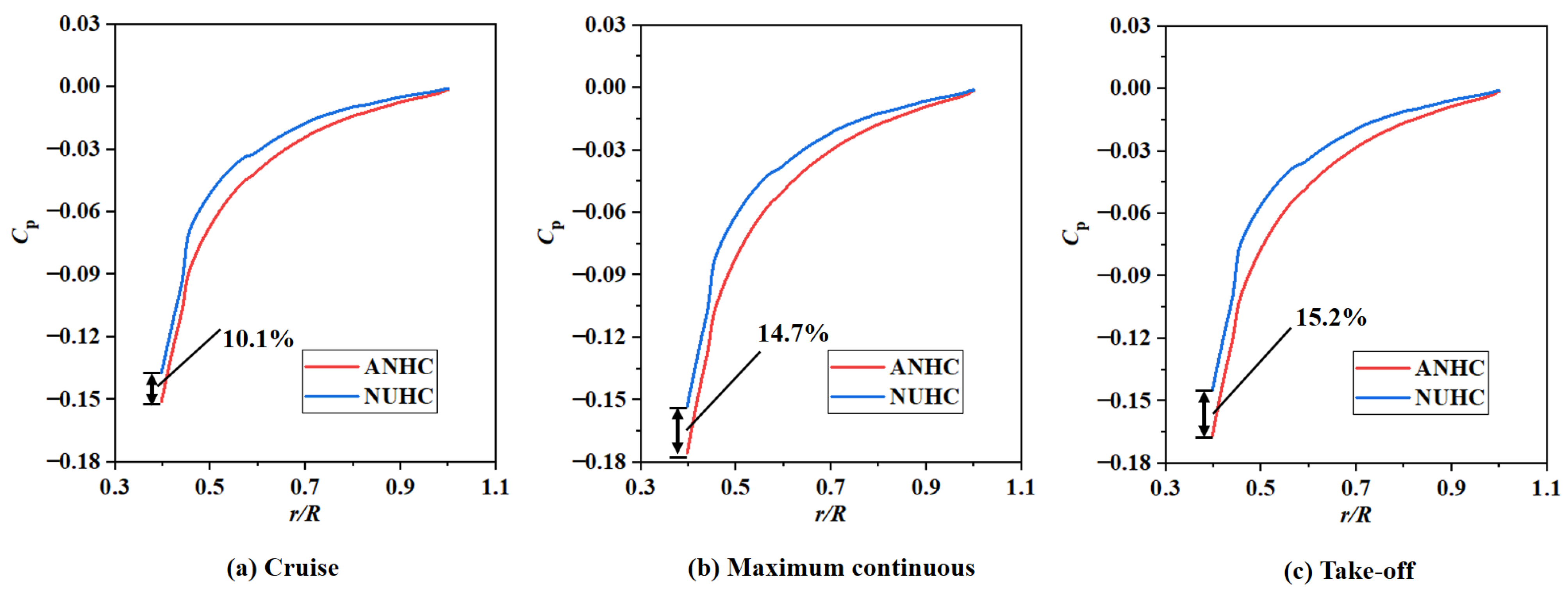
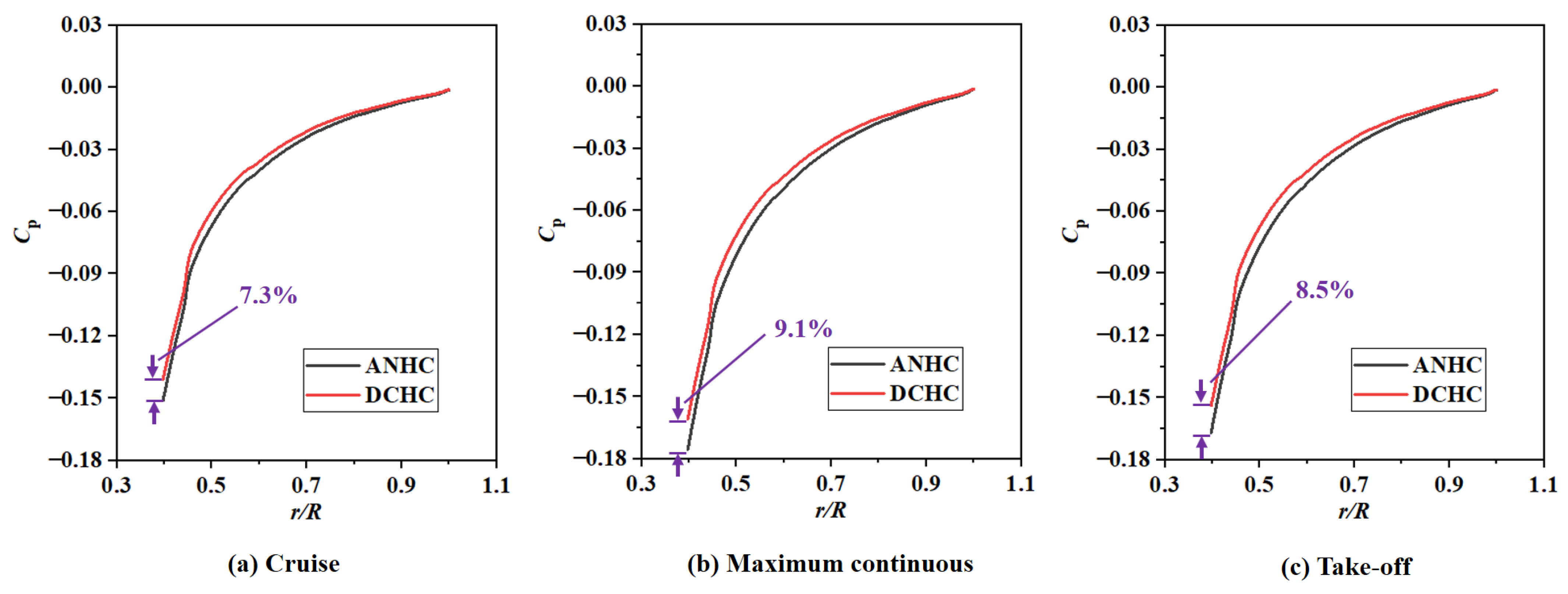
Pressure distribution is related to flow resistance, which is an important flow characteristic of the rotor-stator cavity. The pressure coefficient was adopted to describe the pressure distribution of the rotating disk surface, which is defined as:
C p   =   p p s , out 1 / 2 ρ Ω 2 r 2
where r is the radius.
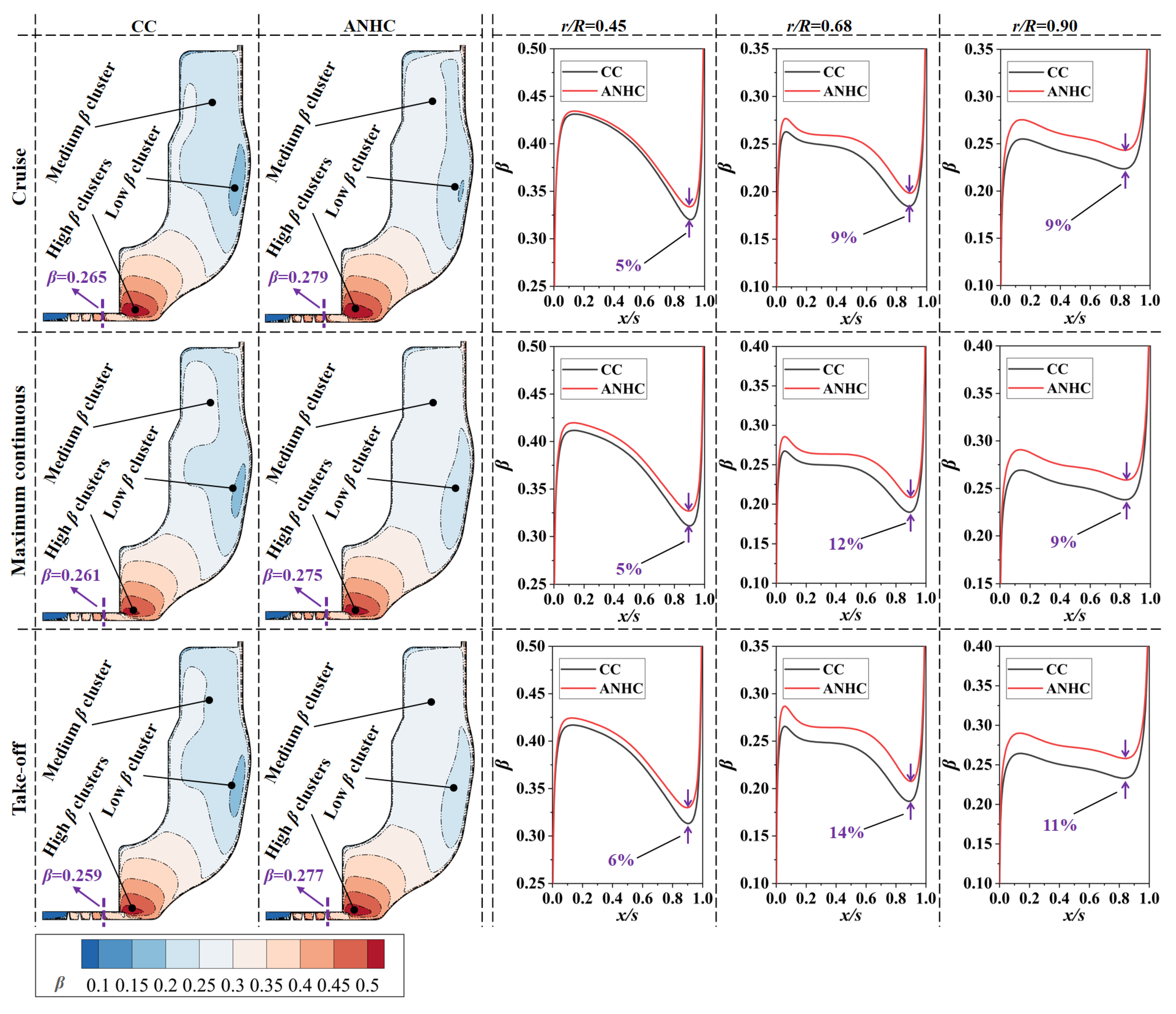
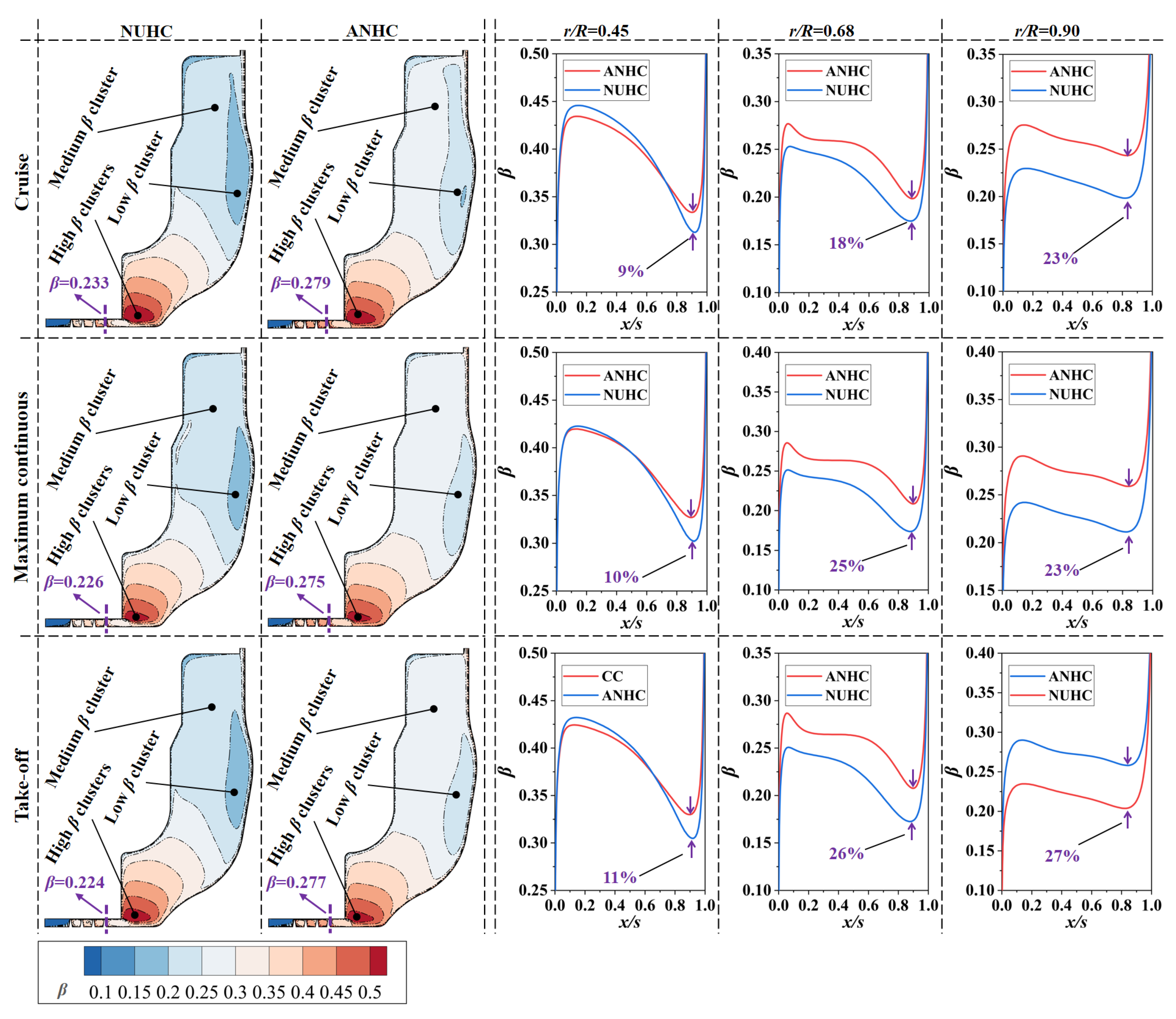
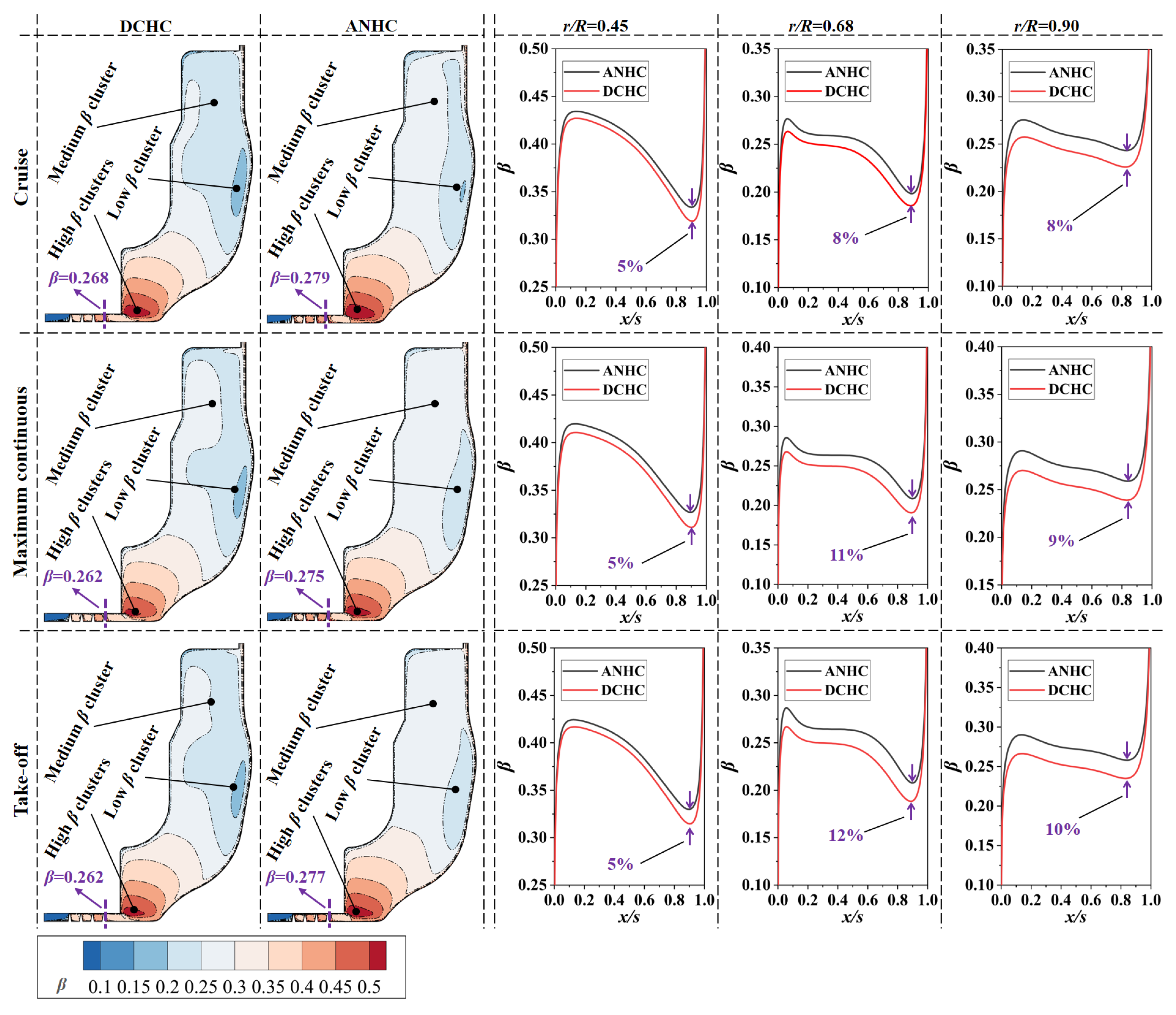
Swirl ratio is the ratio of air swirl velocity ( V θ ) to local disk rotating speed, reflecting the relative circumferential velocity between cooling air and rotating disk.
β   =   V θ Ω r
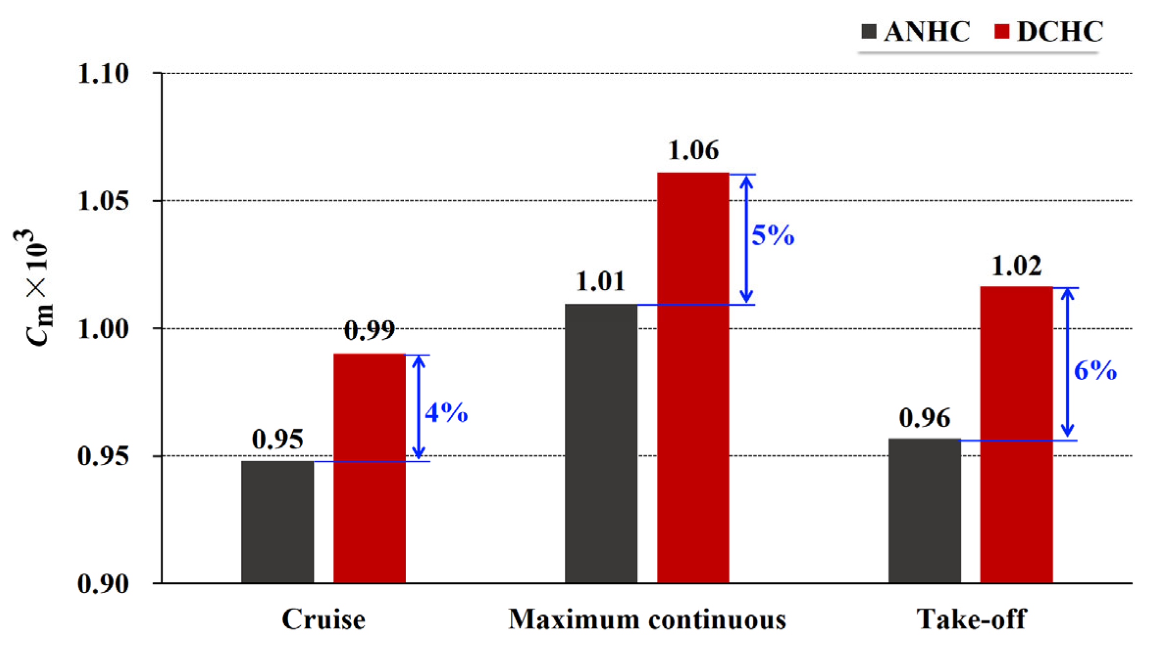
The moment coefficient is the dimensionless friction moment of the rotating disk.
C m   =   M 1 / 2 ρ Ω 2 r 0 5
where M is the friction moment of the rotating disk.
For the aspect of heat transfer, the Nusselt number represents the thermal resistance ratio of heat conduction and convective heat transfer in the fluid layer near the disk surface, reflecting the intensity of convective heat transfer.
N u   =   h r k f
h   =   q T w T t , in
where h is the convective heat transfer coefficient, k f is the thermal conductivity of the fluid, q is the heat flux of the rotating disk surface, and T w is the temperature of the rotating disk surface.
The solid temperature of the rotating disk (T) is expressed by dimensionless metal temperature.
Θ   =   T T t , in TET T t , in
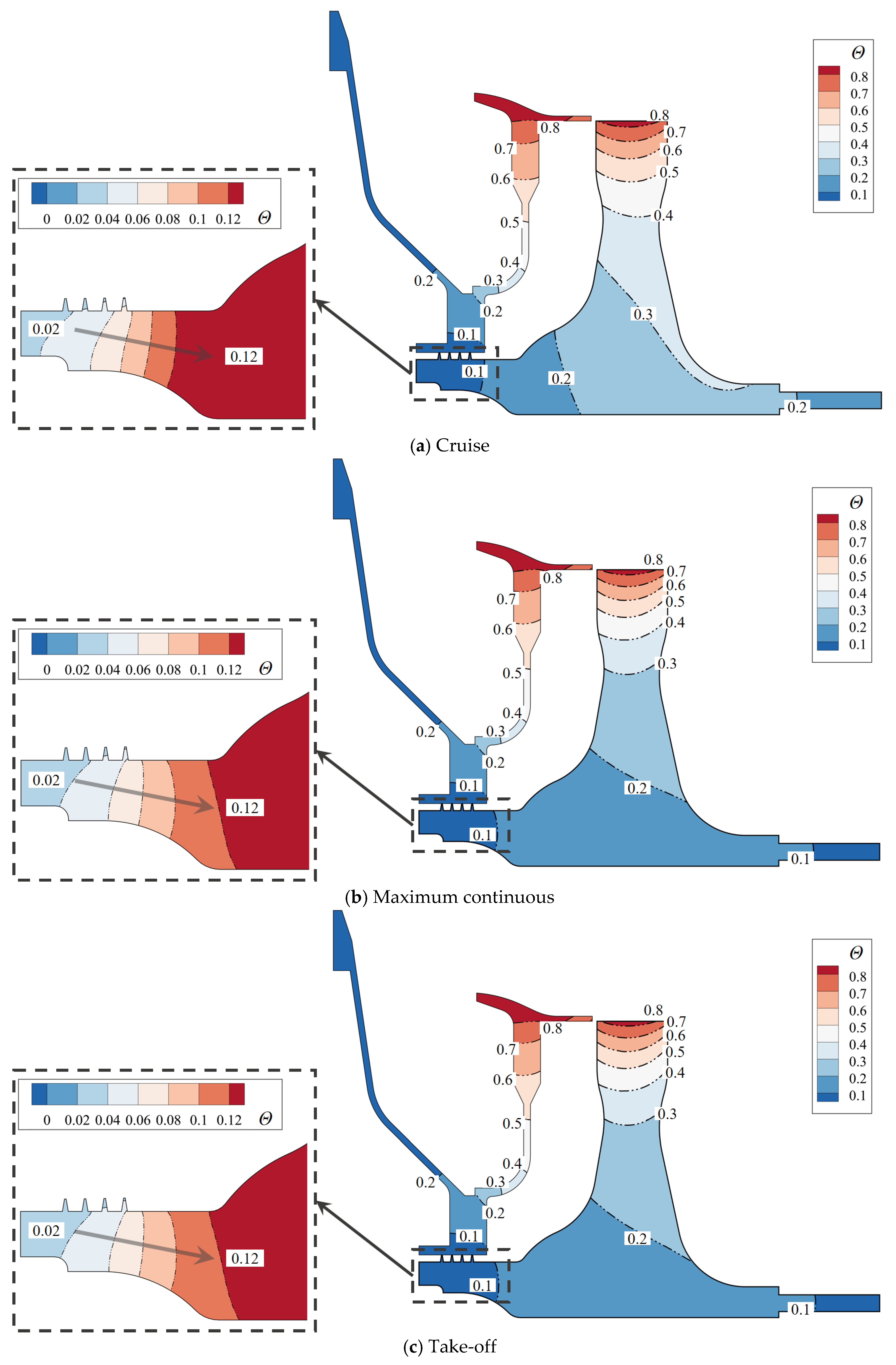
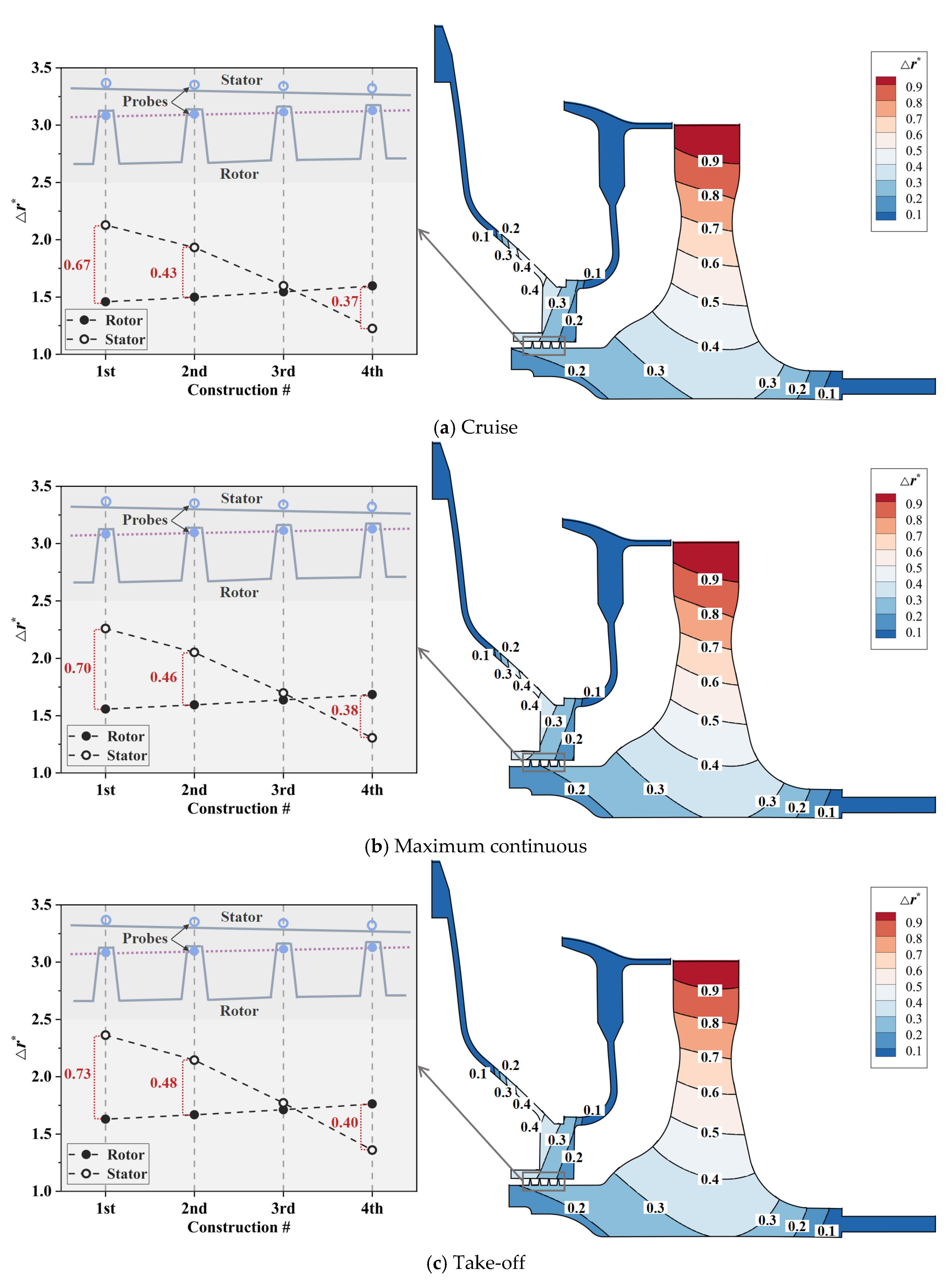
In the present research, the cruise state, maximum continuous state, and take-off state were selected as the typical operating states of the turboshaft engine. The aero-thermo-elasto coupling analysis was conducted to explore the swirl flow and heat transfer characteristics in the rotor-stator cavity in consideration of the inlet seal thermal deformation effect. The centrifugal load of the turbine blade, C B , was equivalent to the uniform load on the turbine disk rim. The boundaries ➀–➆ in Figure 2 were all given the boundary conditions of convection heat transfer. The reference temperatures of convective heat transfer were the fluid temperatures near the wall, which could be gained from the SAS flow network solver [2]. Convective heat transfer coefficients were derived from the correction formulas, as shown in Appendix C. The boundary parameters of these three typical operating points are shown in Table 2.

2.5. Model Verification

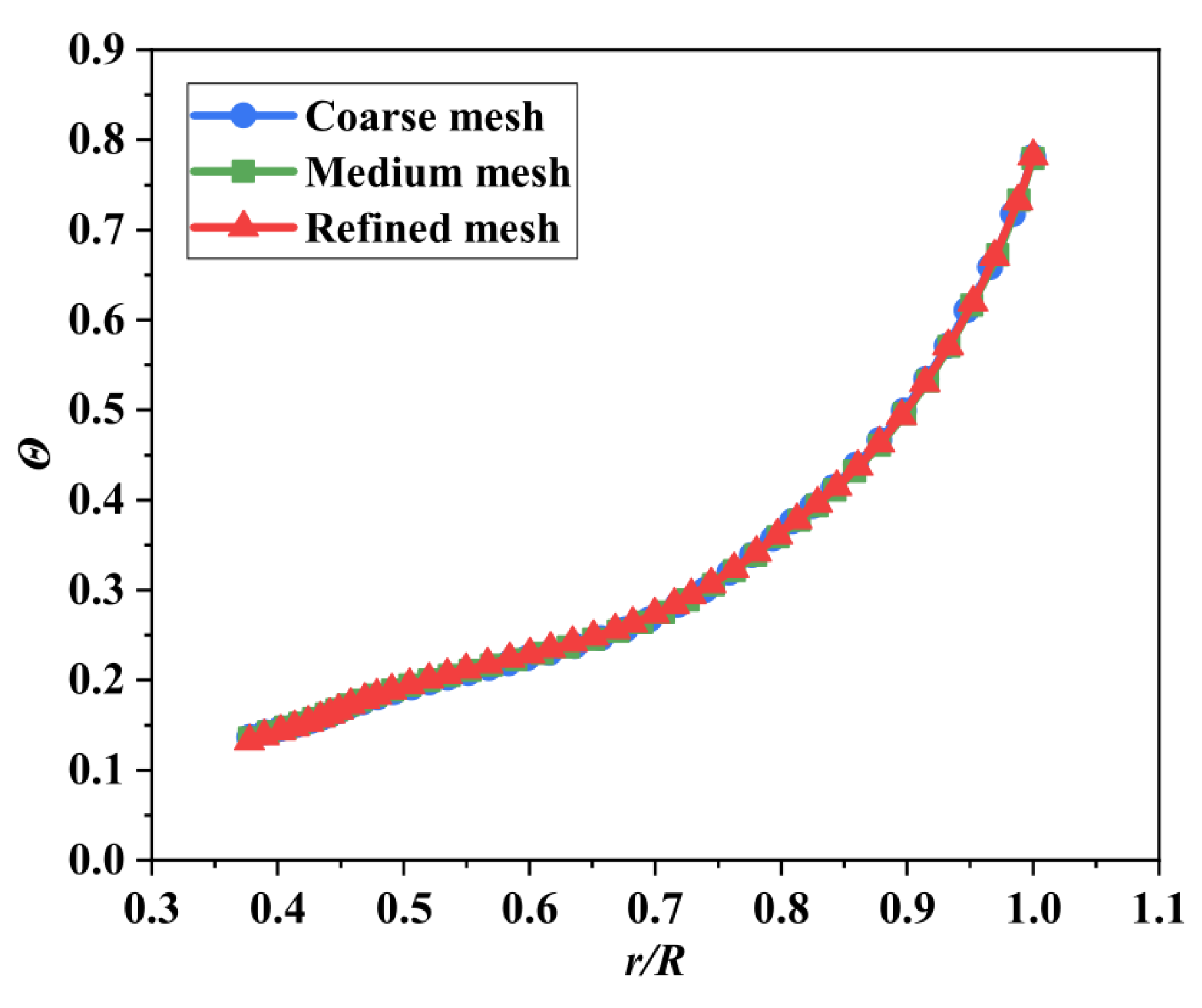
A grid sensitivity analysis was also performed to define the mesh size. Three sets of grids with different element numbers were established. The element numbers of coarse, medium, and refined meshes were 0.31 million, 0.62 million, and 1.20 million respectively. Computational convergence was accepted when the residuals of the continuity equation, momentum equation, and energy equation converge to the order of 2 × 10⁻⁶. Figure 7 shows the dimensionless metal temperature on the surface of the turbine disk under cruise state, in which the differences among coarse, medium, and fine grids are no more than 2.5%. The dimensionless metal temperature results can be considered independent from the mesh size. Considering the compromise between simulation accuracy and calculation cost, the medium grids were selected for subsequent calculation and analysis.
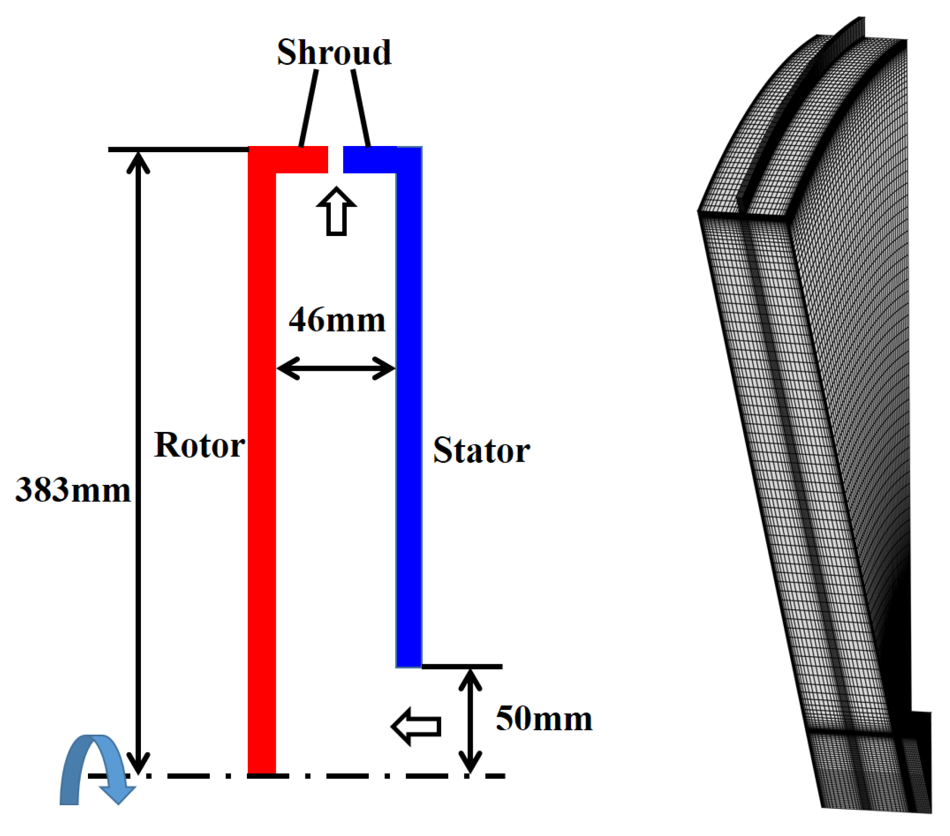
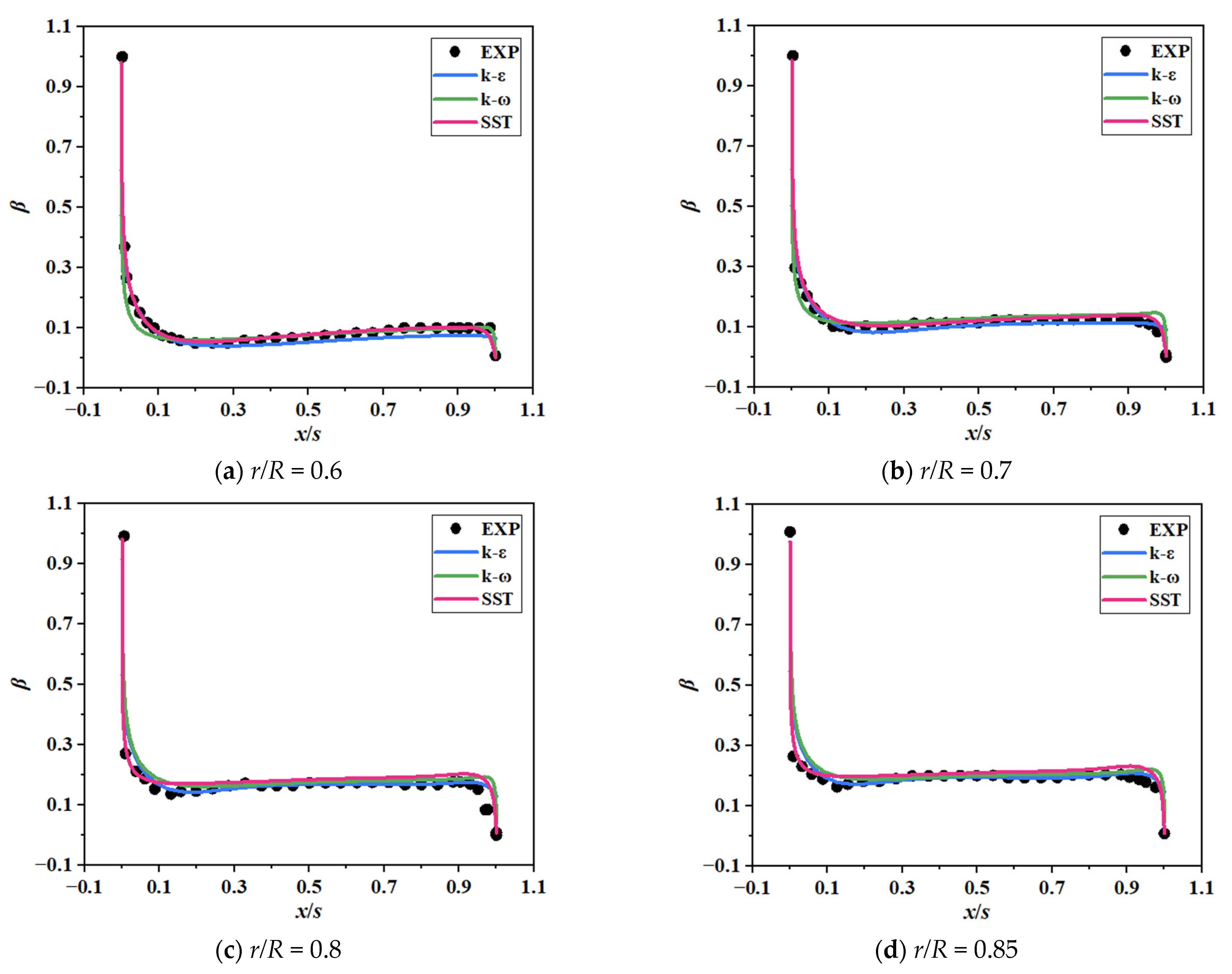
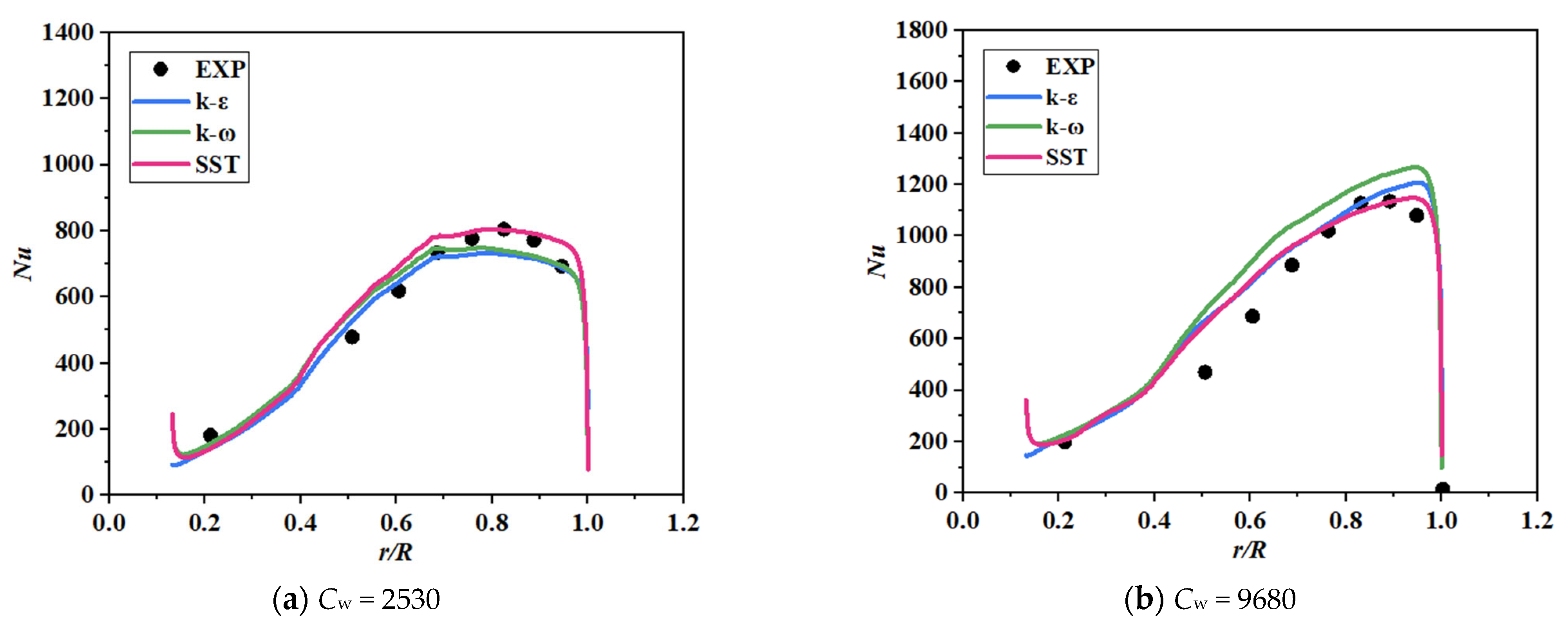
The analysis of convective heat transfer on the surface of the rotating disk is one of the most critical links in the aero-thermo-elasto coupling calculation. In order to verify the accuracy of the numerical simulation method in this paper, experimental data [37] of heat transfer in an air-cooled rotor-stator cavity were used to implement the reliability test. The rotating-disk rig comprised two disks of 762 mm diameter. The axial clearance between the two shrouds was less than 4 mm, and the axial gap ratio for the disks was 0.12. A radial outflow of air could be supplied through the center of the stationary disk (100 mm diameter). The back face of the rotating disk, which was made from steel, was heated by 30 stationary, radiant-heater elements located at an axial distance of approximately 30 mm from the disk. Ten fluxmeters were located at different radial positions, and ten copper-constantan thermocouples were embedded at the same radial locations but displaced tangentially from the fluxmeters. The fluxmeters were calibrated using free-disk tests. The swirl ratio in the cavity and the Nusselt numbers on the surface of the rotating disk were measured in the experiment.
The numerical model was established, as shown in Figure 8. The simulation results were compared with the experiment data in Figure 9 and Figure 10. Three turbulent models (k-ε, k-ω, and SST) were examined in three sets of experiment cases (Cw = 2530, Cw = 6100, and Cw = 9680, in which Cw = m ˙ / π R μ ). Swirl ratios from different turbulent models were validated by experimental data in Figure 9. The SST model performed best, especially at the transition between the core region and near-wall region. Nusselt number distributions from all three turbulent models presented a similar tendency with the experiment data and are shown in Figure 10. The calculation results indicate that the numerical method in the present work can simulate the heat transfer in the rotor-stator cavity with reasonable accuracy. Generally, the SST model had a better performance for swirl flow and heat transfer simulation in the rotor-stator cavity. The SST model modified the definition of the eddy viscosity coefficient and considered the transmission effect of turbulent shear stress. Therefore, the SST model has higher accuracy and credibility in a wide range of flow fields, especially in near-wall free flow. Considering the above advantages, the SST model was used in the subsequent numerical simulation.

3. Influence of Seal Thermal Deformation

3.1. Actual Non-Uniform Hot-Running Clearance (ANHC)

The solid temperature field calculation was the premise of the structural deformation analysis. Figure 11 shows the dimensionless metal temperature distributions in the cruise state, maximum continuous state, and take-off state. Generally, the temperatures of the labyrinth rotor and stator were close to the inlet total temperature of the cooling air, and dimensionless metal temperatures did not exceed 0.1. This is attributed to the strong heat exchange between the cooling air and the labyrinth seal structure. However, from the partially enlarged contour maps, it is clear that there was a temperature gradient along the axial direction of the rotor. The side closer to the turbine disk had a higher temperature, which would cause uneven thermal deformation.
Figure 12 shows the contour maps of the dimensionless radial displacement. The radial deformations of both the rotor and the stator were not uniform in the axial direction. The radial displacement of the rotor close to the turbine disk was larger, while that of the stator away from the turbine disk was larger. The reasons for their uneven radial deformation were also different. The non-uniformity of the rotor was due to the axial temperature gradient, while the non-uniformity of the stator was due to the different structural stiffness of the front and rear sides. Figure 12 also displays the radial deformation of each labyrinth stage. Radial deformation comparison between the stator and rotor showed that: the former was larger than the latter for the first and second stages of the labyrinth, while the latter was larger than the former for the fourth stage of the labyrinth. For the third stage of the labyrinth, the radial deformation of the stator was similar to that of the rotor. As a result, the labyrinth clearance presented a convergent hot-running clearance (HC) profile. Owing to the non-uniform radial deformation, the non-uniformity deformations of the rotor and stator led to an obvious decrease in the minimum tip clearance. The minimum tip clearance was smaller than the CC by 37% for the cruise state, 38% for the maximum continuous state, and 40% for the take-off state. Therefore, the risk of collision and rub between the rotating and stationary parts may be underestimated during the aero-engine operation if the non-uniformity deformation of the labyrinth clearance is ignored.

3.2. Flow Structure

The labyrinth located at the entry of the turbine disk cavity meters the mass flow rate of cooling air entering the downstream rotor-stator cavity. The non-uniformity of the labyrinth clearance has an inevitable impact on the pressure distribution, mass flow rate, and swirl ratio at the inlet of the downstream cavity, resulting in the change of swirl flow and heat transfer in the cavity.
Pressure coefficient distributions of the rotating disk surface under CC and ANHC are compared in Figure 13. The pressure coefficient C p under the ANHC was smaller than those under the CC along the rotating disk surfaces. At the inlet of the rotor-stator cavity, the C p of ANHC was lower than that of the CC by 6.9%, 9.1%, and 8.9% in the cruise state, the maximum continuous state, and the take-off state, respectively. This is attributed to the inlet seal flow effects. The lower C p denotes a greater reverse pressure gradient along with the radial outflow, which means that non-uniformity deformation of the labyrinth clearance may increase the possibility of mainstream high-temperature gas ingress.
The mass flow rate of cooling air is closely related to the pressure distribution in the rotor-stator cavity. Figure 14 shows the flow coefficients of the rotor-stator cavity under CC and ANHC. Compared with the CC, the flow coefficient under the ANHC was reduced by 23–28% in the three states. This is because the minimum tip clearance of the ANHC is smaller than those of the CC (see Figure 12), which is the key factor determining the mass flow rate of cooling air.
Despite the pressure coefficient and flow coefficient differences between CC and ANHC, flow structures in the rotor-stator cavity were similar, indicating that the flow structure is not sensitive to the inlet seal deformation effect. Taking cruise state as an example, flow structures under CC and ANHC are shown in Figure 15. Five zones can be approximately distinguished in the rotor-stator cavity, that is, the upper vortex at the high radius region of the cavity, the lower vortex at the low radius region of the cavity near the rotating disk, the buffer flow between the upper vortex and lower vortex, the radial outflow near the rotating wall, and the inlet seal flow in the labyrinth seal. The cooling air leaks from the inlet labyrinth seal, forming the through-flow in the rotor-stator cavity. Induced by the pump effect of the rotating disk, fluid near the rotating disk flows centrifugally. Fluid near the stationary disk flows centripetally and is transported to the radial outflow near the rotating disk by the upper vortex and lower vortex, supplementing the pumping flow. Since the rotating speed at the high radius region is larger than that at the low radius region, requirements for pumping flow supplement are not the same at different radii. Consequently, two swirling vortices, instead of a single one, occupy the high radius region and low radius region, respectively, between which the buffer flow becomes a transition area.

3.3. Swirl Flow

Swirl flow in the rotor-stator cavity is related to the relative tangential velocity between the fluid and rotating disk surface, affecting both windage torque [5] and heat transfer [15] of the rotating disk surface. To gain insight into the fluid dynamic mechanisms of swirl flow, Figure 16 shows the swirl ratio distributions under the CC and the ANHC. In view of the similar flow structure depicted in Figure 15, no obvious difference in swirl ratio distribution can be observed between the cases of CC and ANHC. According to the conservation principle of angular momentum, the tangential velocity would increase when flowing from a high radius to a low radius and decrease when flowing from a low radius to a high radius. Thus, under the transportation of the lower vortex, a high swirl ratio cluster exists at the vortex bottom near the stationary disk, and a low swirl ratio cluster exists at the vortex top near the rotating disk. The radial range occupied by the upper vortex was smaller than that of the lower vortex, so the swirl ratio gradient was not obvious as that in the lower vortex, forming a medium swirl ratio cluster in the upper vortex.
Figure 16 also shows swirl ratio distributions in the axial direction at three radii, r/R = 0.45, r/R = 0.68, and r/R = 0.90, corresponding to the lower vortex, buffer flow, and upper vortex. Here, x/s is the dimensionless axial position, which is the ratio of the distance from the stationary disk to the cavity width. The swirl ratio distributions in the axial direction under CC and ANHC were almost the same. The swirl ratio in the boundary layer of the rotating disk approaches 1, and that of the stationary disk approaches 0. However, the swirl ratio of centripetal flow near the stationary disk was much higher than that of centrifugal flow near the rotating disk. Comparison between the cases of the CC and the ANHC indicates that the maximum deviation of swirl ratio reached up to 6–14%.
The swirl flow difference can be attributed to the effect of inlet seal thermal deformation. Figure 17 compares the swirl flow around the outlet of the labyrinth seal. The swirl velocity of seal outflow was much smaller than that of the centripetal cavity flow, resulting in a strong circumferential shear interaction at the entry of the rotor-stator cavity. Due to the non-uniform seal clearance effect, windage heating and swirl development characteristics inside the labyrinth seal [38] become different from that of the uniform seal clearance. Compared to CC, the swirl ratio of seal outflow under ANHC was higher, so the mixed airflow carried more swirl velocity into the disk cavity. The inlet labyrinth seal under ANHC was more favorable to transport swirl flow into the rotor-stator cavity. This explains why the high swirl ratio cluster expands and the low swirl ratio cluster shrinks in the condition of ANHC, as shown in Figure 16.
Moment coefficients of the rotating disk surface under CC and ANHC are compared in Figure 18. Affected by the inlet seal thermal deformation, the moment coefficients under the ANHC were lower than those under CC by 5–6% in the three hot-running states. It is well-known that the increase in the swirl ratio contributes to the reduction in the moment coefficient. A higher swirl ratio, meaning lower relative tangential velocity between the cooling air and rotating disk surface, results in less friction torque. Thus, the reduction of the moment coefficient in the case of the ANHC can be explained by the combined effect of the swirl ratio increase at the seal outlet and the flow coefficient decrease.

3.4. Heat Transfer

Heat transfer in the rotor-stator cavity is closely related to the mass flow rate and swirl flow of the through-flow. Figure 19 shows the Nusselt numbers of the rotating disk surfaces under the CC and the ANHC. Compared with the CC, the Nusselt numbers under the ANHC were reduced by 11–32% for the cruise state, by 10–66% for the maximum continuous state, and by 15–69% for the take-off state, highlighting the thermal deformation effect. In the rotor-stator cavity, the heat transfer at the low-radius position was directly impacted by the cooling air from the labyrinth outlet, while the heat transfer at the high-radius position was dominated by the rotation. Therefore, the variation of the mass flow rate of cooling air, induced by the thermal deformation of the labyrinth, has a more obvious impact on the Nusselt number at the low radius of the rotating disk rather than those at the high radius. In general, the Nusselt number of the rotating disk surfaces under the ANHC was much smaller than those under the CC, indicating that the effect of the thermal deformation of the seal clearance cannot be neglected for the heat transfer analysis of the downstream rotor-stator cavity. The effect of the labyrinth clearance on the convective heat transfer is essentially caused by changing the cooling air flow rate and swirl state. The increase in the cooling air flow rate means a larger flow velocity around the disk. The decrease in the swirl ratio can enlarge the relative tangential velocity between the air and the disk. The increased flow velocity brings a thinner heat boundary layer, thus enhancing the convective heat transfer intensity.
Figure 20 shows the dimensionless metal temperatures of the rotating disk surface under the CC and the ANHC. In view of the influence of inlet seal flow on the heat transfer coefficient, the dimensionless metal temperature of the rotating disk under the ANHC was higher than that under the CC along the whole rotating disk surface. A comparison between the cases of the CC and the ANHC shows that the thermal deformation of the labyrinth leads to an increase in the dimensionless metal temperature by up to 22%. Similar to the Nusselt numbers, the dimensionless metal temperature was more affected at the low radius and less affected at the high radius. It is inferred that the temperature at the core of the turbine disk is dominated by the cooling air in the SAS, and the temperature at the rim of the disk is dominated by the mainstream high-temperature gas. When analyzing the heat transfer of the turbine disk, if the thermal deformation of the labyrinth is ignored, the temperature at the center of the turbine disk would be underestimated, which could cause an inaccurate assessment of the turbine disk service life and endanger the safety of the engine.

4. Influence of Seal Clearance Non-Uniformity

4.1. Nominal Uniform Hot-Running Clearance (NUHC)

In previous studies, the average hot-running clearance was implemented to evaluate the effect of thermal deformation on the performance of a labyrinth seal without consideration of the deformation non-uniformity [24]. To reveal the influence of non-uniform labyrinth clearance, the Nominal Uniform Hot-running Clearance (NUHC) and Actual Non-uniform Hot-running Clearance (ANHC) are distinguished and compared in the present paper. The NUHC is defined as the arithmetic mean of tip clearances.
Figure 21 shows the profiles of CC, ANHC, and NUHC in the cruise state, the maximum continuous state, and the take-off state, respectively. Since the seal clearance profile tends to be a convergent type caused by the non-uniform deformation, it is not surprising that the first tip clearance was larger than the last tip clearance by 104–113% of CC. The NUHC was larger than the CC. The dimensionless NUHCs for the three states were 1.20, 1.21, and 1.22, respectively. However, the dimensionless minimum tip clearance of the ANHC was 0.63, 0.62, and 0.60 in the three states, respectively. The minimum tip clearance is the key parameter affecting the performance, safety, and stability of a labyrinth seal [38]. Current studies imply that the actual hot-running labyrinth clearance would be optimistically estimated if the non-uniform clearance were neglected.
Effects of non-uniform seal clearance on the fluid flow in the rotor-stator were also analyzed. Figure 22 depicts the comparison of the pressure coefficient between ANHC and NUHC. The C p at the cavity inlet under the NUHC was higher than that under the ANHC by 10.1%, 14.7%, and 15.2% in the three hot-running states, respectively. The higher C p at the cavity inlet attributes to a smaller reverse pressure gradient along with the radial outflow. As a result of the NUHC, the flow coefficient of the rotor-stator cavity increased unrealistically by 53%, 56%, and 62% in comparison with these under the ANHC, as shown in Figure 23, which means that the mass flow rate of the purge flow will be overestimated, and the possibility of mainstream high-temperature gas ingress will be underestimated.

4.2. Effect on Swirl Flow

Although no obvious difference in the swirl ratio distributions was observed between the cases of ANHC and NUHC, the areas of the two high swirl ratio cluster regions under the NUHC were smaller than those under the ANHC, as shown in Figure 24. Particularly, at the outlet of the labyrinth seal, the swirl ratio under the NUHC was lower than those under the ANHC by 11–15% in the three states, which is even more obvious than the difference between the CC and the ANHC (see Figure 16), highlighting the non-uniformity effect of the inlet seal clearance in the swirl flow analysis. Swirl ratio distributions in the axial direction were also compared in the lower vortex region (r/R = 0.45), the buffer flow region (r/R = 0.68), and the upper vortex region (r/R = 0.90). Since the flow structure is less affected by the inlet seal deformation, the distribution tendencies of the ANHC and the NUHC were similar, but the quantity disparities were obvious. Swirl ratios in the cases of the NUHC were smaller than those of the ANHC by up to 11% at r/R = 0.45, 26% at r/R = 0.68, and 27% at r/R = 0.90.
The windage torque of the rotating disk surface is related to the swirl flow in the rotor-stator cavity. Consequently, the moment coefficient of the rotating disk surface was also influenced by the inlet seal clearance non-uniformity, shown as the comparison between ANHC and NUHC in Figure 25. The moment coefficients under the NUHC were higher than those under ANHC by 12–14% in the three hot-running states. The results indicate that substituting the NUHC for the ANHC will lead to an inaccurate windage torque analysis.

4.3. Effect on Heat Transfer

With the combined effect of mass flow rate and swirl flow in the rotor-stator cavity, heat transfer between the cooling air and the rotating disk presented a profound discrepancy under the ANHC and the NUHC. As shown in Figure 26, the Nusselt number under the NUHC was higher than that under the ANHC by 23–51% for the cruise state, by 23–81% for the maximum continuous state, and by 24–79% for the take-off state, highlighting that the inlet seal clearance non-uniformity effect cannot be neglected in the heat transfer analysis. As a result, the dimensionless metal temperature of the rotating disk under the NUHC was lower than that under the ANHC, as shown in Figure 27. Up to a 36% maximum difference in the dimensionless metal temperature between the cases of the NUHC and the ANHC was found, which means the temperature of the rotating disk will be underestimated substantially if the non-uniform clearance of the inlet seal is not fully considered. As one of the ELLP, the service life of the rotating disk will be incorrectly analyzed.

5. Seal Clearance Compensation

5.1. Divergent Compensating Cold-Built Clearance (DCCC)

The non-uniform clearance profile of the labyrinth not only increases the risk of collision and rubbing between the rotor and stator, threatening the structural integrity, but also weakens the heat transfer in the rotor-stator cavity, resulting in the increase of the downstream rotating disk temperature and the reduction of the service life of ELLP. In order to eliminate the adverse effect of non-uniform deformation of the inlet seal clearance, a divergent compensating cold-built clearance (DCCC) is proposed to offset the deformations of the labyrinth.
The divergent compensating hot-running clearance (DCHC) was obtained, as shown in Figure 28. After the compensation design, the uniformity of the hot-running clearance was significantly improved. The minimum tip clearances of the DCHC in the cruise state, maximum continuous state, and take-off state were larger than those of ANHC, which would reduce the risk of collision between the rotor and stator. Moreover, the increase in minimum tip clearance also contributed to a lift of the flow coefficients. It can be seen from Figure 29 that the flow coefficients of the DCHC are larger than those of the traditional scheme by 21–25% in the three hot-running states, which brings potential benefits to preventing the mainstream gas ingress and cooling the hot components.
Figure 30 compares pressure coefficient distributions of the rotating disk surfaces under the ANHC and DCHC. The pressure coefficients under DCHC were higher than those under ANHC along the whole rotating disk surface, in particular at the inlet of the cavity (by 7.3–9.1% in the three hot-running states). Thus, the divergent clearance compensation can effectively increase the pressure coefficient at the inlet of the rotor-stator cavity. The decreased radial pressure gradient is beneficial to the function of the purge flow.

5.2. Compensation for Swirl Flow

To evaluate the effect of seal clearance compensation on the swirl flow in the rotor-stator cavity, Figure 31 shows the difference in swirl ratio contours between the ANHC and the DCHC. After the compensation design, the area of the high swirl ratio cluster expanded while the area of the low swirl ratio cluster shrunk, resulting in a decrease in the overall level of swirl ratio in the cavity. As for the outlet of the labyrinth seal, the swirl ratio under the DCHC was lower than that under ANHC, which is one of the important reasons for the swirl suppression in the cavity.
Swirl ratio distributions in the three regions of the lower vortex (r/R = 0.45), the buffer flow (r/R = 0.68), and the upper vortex (r/R = 0.90) are also compared in Figure 31. Previous analysis indicated that the inlet seal flow has little effect on the flow structure. Thus no obvious difference in the distribution tendency of the swirl ratio can be observed between the DCHC and the ANHC. However, the swirl ratios under the DCHC were smaller than those under the ANHC. The maximum deviations were 5% at r/R = 0.45, 8–12% at r/R = 0.68, and 8–10% at r/R = 0.90 in the three hot-running states. With the swirl suppression in the cavity after clearance compensation, an increase in the moment coefficient of the rotating disk surface was found, as seen in Figure 32. The increased windage torque needs extra power input to balance, which is an adverse factor brought by the clearance compensation. Therefore, a trade-off is needed between windage loss and performance and safety gain with the clearance compensation design.

5.3. Compensation for Heat Transfer

Divergent compensation for the labyrinth clearance is capable of increasing the mass flow rate of cooling air and magnifying the relative velocity between airflow and the rotating disk by weakening the non-uniformity of the inlet seal clearance, which is beneficial to the rotating disk cooling.
Figure 33 and Figure 34 compare the Nusselt number and the dimensionless metal temperature of the rotating disk surface under the DCHC and the ANHC, respectively. After clearance compensation design, the Nusselt number increased up to 31–66% in the three hot-running states. It can be concluded that the divergent compensation design for the labyrinth clearance can significantly increase the heat transfer coefficient, in particular in the lower radius region. Since the heat transfer in the rotor-stator cavity is enhanced, the temperature drop of the rotating disk can be expected. Compared with the traditional scheme, the dimensionless metal temperature decreased up to 13–19%. With the help of the compensation design, the temperature of the rotating disk surface can be reduced effectively, which could increase the service life of ELLP and improve the safety of the engine.
As an important function of SAS, cooling hot components like rotating turbine disks are the key factors of the rotor-stator cavity design. Despite the slight increase in windage torque, the compensation design for the inlet labyrinth clearance can significantly improve the cooling performance of the rotor-stator cavity, indicating that the compensation method is worthy of attention for further theoretical research and engineering applications.

6. Conclusions

This investigation focused on swirl flow and heat transfer in a rotor-stator cavity with consideration of the inlet seal thermal deformation effect, including the effect of hot-running clearance and non-uniform clearance. To reflect the two-way aero-thermo-elasto coupling interaction among elastic deformation, leakage flow, and heat transfer, a numerical framework was established by integrating CHT analysis and structural FEM analysis. Three typical operating states of the turboshaft engine (cruise state, maximum continuous state, and take-off state) were analyzed. Characteristics of swirl flow and heat transfer in the rotor-stator cavity were discussed under the cold-built clearance (CC), the actual non-uniform hot-running clearance (ANHC), and the nominal uniform hot-running clearance (NUHC). Finally, a clearance compensation method was proposed and validated to weaken the adverse effects caused by the non-uniformity of seal clearance.
The following conclusions can be drawn in this investigation.
  • Due to the axial temperature gradient and inconsistent structural stiffness, uneven deformations of rotor and stator assemblies may lead to a non-uniform hot-running profile of the inlet labyrinth seal, whose minimum tip clearance is significantly smaller than that of the CC (up to 40% in the current study), increasing the risk of collision and rubbing between the rotational and stationary parts. The flow structure in the rotor-stator cavity is not sensitive to the inlet seal flow. However, the ANHC induced by the non-uniform deformation would lead to a decrease in the flow coefficient (maximum 28% against CC) and pressure coefficient (maximum 9.1% against CC), which is not beneficial to preventing mainstream high-temperature ingress.
  • The non-uniform deformation of the labyrinth seal leads to the increase of the swirl ratio at the outlet of the labyrinth seal, increasing the overall swirl level in the rotor-stator cavity and resulting in decreasing windage torque of the rotating disk surface. The Nusselt number of the rotating disk is found to be reduced by up to 69%, and the dimensionless metal temperature of the rotating disk correspondingly increases by up to 22% when the effect of thermal deformation is considered.
  • The results of this study indicate that the effect of the non-uniform thermal deformation of the seal clearance cannot be neglected for the swirl flow and heat transfer analysis of the downstream rotor-stator cavity. If the non-uniformity of the seal clearance is not considered and the NUHC is substituted for the ANHC, the Nusselt number of the rotating disk will be overestimated, and the dimensionless metal temperature of the rotating disk will be underestimated, leading to an inaccurate heat transfer analysis. As a result, the service life of the rotating disk will be incorrectly analyzed.
  • A clearance compensation method is proposed to offset the non-uniformity of seal clearance deformation. Using a divergent compensating cold-built clearance, the uniformity of the hot-running clearance is obviously significantly improved. The pressure coefficient and Nusselt number of the rotor-stator cavity are increased, resulting in the increase in the flow coefficient of the rotor-stator cavity and the decrease in the dimensionless metal temperature of the rotating disk. Therefore, the proposed method could promote the ability to purge flow and cool the disk of the rotor-stator cavity.

Author Contributions

Conceptualization, Y.S. and P.L.; methodology, Y.S.; validation, Y.S., T.Q. and C.L.; formal analysis, Y.S.; investigation, Y.S.; resources, C.Q. and D.Y.; data curation, C.Q. and D.Y.; writing—original draft preparation, Y.S.; writing—review and editing, Y.S. and P.L.; visualization, Y.S. and P.L.; supervision, S.D. and C.L.; project administration, S.D. and C.L.; funding acquisition, S.D. and C.L. All authors have read and agreed to the published version of the manuscript.

Funding

This research was funded by the National Science and Technology Major Project of China, grant number J2019-III-0003-0046, and the Special Research Project of Chinese Civil Aircraft, grant number MJ-2018-D-21.

Data Availability Statement

The data used to support the findings of this paper are contained in the text, and some of the cited data can be found in the public literature.

Acknowledgments

The authors thank the Hunan Aviation Powerplant Research Institute for the approval to publish.

Conflicts of Interest

The authors declare no conflict of interest.

Nomenclature

A 0 Area, m2
bChord length of blade or vane, m
BLabyrinth pitch, m
cTip clearance of labyrinth, m
CConstant
c 0 Cold-built clearance of labyrinth, m
C B Equivalent blade load, Pa
C m Moment coefficient
c * Dimensionless tip clearance of labyrinth
c ANHC * Dimensionless actual non-uniform hot-running clearance of labyrinth
c CC * Dimensionless cold-built clearance of labyrinth
c NUHC * Dimensionless nominal uniform hot-running clearance of labyrinth
CDPCompressor discharge pressure, Pa
EElastic modulus, Pa
GrGrashov number
hConvective heat transfer coefficient, W/(m2·K)
HLabyrinth tooth height, mm
MFriction moment of rotating disk, N·m
m ˙ Mass flow rate of disk cavity, kg/s
NConstant
NuNusselt number
N u s Nusselt number of stationary pipe flow
PrPrandtl number
p s , out Static pressure of disk cavity outlet, Pa
p s , out * Dimensionless static pressure of disk cavity outlet
p t , in Total pressure of labyrinth inlet, Pa
p t , in * Dimensionless total pressure of labyrinth inlet
rradius, m
RGas constant, J/(kg·K);
r 0 Turbine disk radius, m
r 1 Radius of inlet labyrinth rotor, m
r 2 Inner radius of turbine disk, m
ReReynolds number
R e ω Rotational Reynolds number
Δ r Radial deformation, m
Δ r * Dimensionless radial deformation
sWidth of the rotor-stator cavity, m
SWidth of blade or vane, m
S geo Similar geometric parameter
tCascade pitch of blade or vane, m;Labyrinth tip width, m
TTemperature, K
TETTurbine entry temperature, K
T 0 Ambient temperature, K;Sutherland reference temperature, K
T s Sutherland constant, K
T w Disk surface temperature, K
T t , in Total temperature of labyrinth inlet, K
T t , in * Dimensionless total temperature of labyrinth inlet
V θ Tangential velocity, m/s
xDistance to the stationary disk, m
Greek symbols
αThermal expansion coefficient, 1/°C;inclination angle, degree
βSwirl ratio
β 1 Flow angle of the cascade inlet, degree
β 2 Flow angle of the cascade outlet, degree
εPoisson’s ratio;Rotation correction factor
φFlow coefficient
λThermal conductivity, W/(m·K)
λ 0 Sutherland reference conductivity, W/(m·K)
μDynamic viscosity, Pa·s
μ 0 Sutherland reference viscosity, Pa·s
ΘDimensionless metal temperature
ρDensity of labyrinth inlet, kg/m3
ΩRotating speed, rpm
Abbreviations
ANHCActual non-uniform hot-running clearance
CCCold-built clearance
CDPCompressor discharge pressure
CFDComputational fluid dynamics
CHTConjugate heat transfer
DCCCDivergent compensating cold-built clearance
DCHCDivergent compensating hot-running clearance
ELLPEngine life limited parts
FEMFinite element method
FVMFinite volume method
HCHot-running clearance
NUHCNominal uniform hot-running clearance
SASSecondary air system
SSTShear Stress Transport
TETTurbine entry temperature

Appendix A

In the numerical simulation, the fluid is regarded as ideal gas, and dynamic viscosity and thermal conductivity follow Sutherland formula.
Dynamic viscosity:
μ μ 0   =   T T 0 1.5 T 0 + T s T + T s 1.5
In Equation (A1), μ 0 = 1.7161 × 10 5 (Pa·s), T 0 = 273.16 K, and T s = 124 K.
Thermal conductivity:
λ λ 0   =   T T 0 1.5 T 0   + T s T + T s 1.5
In Equation (A2), λ 0   =   0.02415 (W/(m·K)), T 0 = 273.16 K, and T s = 194 K.

Appendix B

In this work, the effects of temperature on the thermal and mechanical properties of solid materials are considered. The density of stationary solid material is 8440 kg / m 3 . Other thermal and mechanical properties of stationary solid material are shown in Table A1, Table A2 and Table A3, respectively. The density of rotational solid material is 8140 kg / m 3 . Other thermal and mechanical properties of rotational solid material are shown in Table A4, Table A5 and Table A6, respectively.
Table A1. Thermal conductivity (λ) of stationary solid material.
T/°C31114220332437543
λ/[W/(m·K)]9.6210.7912.4214.1515.7317.41
T/°C649754866975
λ/[W/(m·K)]19.0920.8222.7524.94
Table A2. Elastic modulus (E) and Poisson’s ratio (ε) of stationary solid material.
T/°C2095205315425540
E/GPa205200195190185175
ε0.3080.310.3120.3130.3120.321
T/°C650760870
E/GPa170170146
ε0.3280.3290.33
Table A3. Thermal expansion coefficient (α) of stationary solid material.
T/°C20–9020–20320–32520–43020–536
α/(1/°C)1.277 × 10−51.314 × 10−51.335 × 10−51.363 × 10−51.409 × 10⁻⁵
T/°C20–65020–75620–87320–928
α/(1/°C)1.477 × 10−51.539 × 10−51.591 × 10−51.631 × 10−5
Table A4. Thermal conductivity (λ) of rotational solid material.
T/°C20100200300400500
λ/[W/(m·K)]12.0912.81415.5117.0818.38
T/°C6007008009001000
λ/[W/(m·K)]19.8321.7823.8725.7127.35
Table A5. Elastic modulus (E) and Poisson’s ratio (ε) of rotational solid material.
T/°C20100200300400500
E/GPa227222217212207202
ε0.350.350.360.360.370.37
T/°C600650700750800
E/GPa196192189184182
ε0.380.380.380.390.39
Table A6. Thermal expansion coefficient (α) of rotational solid material.
T/°C25–5025–10025–20025–30025–400
α/(1/°C)8.615 × 10−61.034 × 10−51.105 × 10−51.155 × 10−51.194 × 10⁻⁵
T/°C25–50025–60025–70025–800
α/(1/°C)1.228 × 10−51.255 × 10−51.307 × 10−51.380 × 10−5

Appendix C

The boundaries ➀–➆ in Figure 2 are all given the boundary conditions of convection heat transfer. Convective heat transfer temperatures are the fluid temperature near the wall, and convective heat transfer coefficients are derived from the correction formulas.
Boundary ➀: heat transfer correction of turbine vane end-wall [39].
N u   =   0.032 ( 1 + 0.7 S geo 0.54 ) R e 0.8
S geo   =   sin β 1 sin β 2 2 S / b t / b · sin β 1 + β 2 cos 2 β 1 β 2 2 0.5
In Equation (A3), S geo is a similar parameter including the influence of the main geometric parameters of the cascade, and Re is the Reynolds number at the exit of the turbine guide. In Equation (A4), β 1 and β 2 are flow angles of the vane cascade inlet and outlet, S is vane width, b is vane chord length, and t is vane pitch.
Boundary ➁: heat transfer correction of turbine disk rim [40].
N u   =   0.206 K ω S geo 0.58 R e 0.66
S geo   =   sin β 1 sin β 2 2 S / b t / b · sin β 1 + β 2 cos 2 β 1 - β 2 2 0.5
In Equation (A5), K ω is the rotation correction factor, S geo is a similar parameter including the influence of the main geometric parameters of the cascade, and Re is the Reynolds number at the exit of the turbine blades. In Equation (A6), β 1 and β 2 are flow angles of the blade cascade inlet and outlet, S is blade width, b is blade chord length, and t is blade pitch.
Boundary ➂: heat transfer correction of natural convection [41].
N u   =   0.59 GrPr 0.25
In Equation (A7), Gr is the Grashov number and Pr is the Prandtl number.
Boundary ➃: heat transfer correction of flat plate convection [41].
N u   =   0.664 R e 1 / 2 P r 1 / 3
In Equation (A8), Re is the Reynolds number and Pr is the Prandtl number.
Boundary ➄: heat transfer correction of pipe flow [41].
N u   =   0.023 R e 0.8 P r 0.4
In Equation (A9), Re is the Reynolds number and Pr is the Prandtl number.
Boundary ➅: heat transfer correction of rotating pipe flow [39].
N u   =   ε N u s
ε   =   1 - th   [ 1 + 0.000175 R e ω R e 0.658 exp ( 0.03 Re ω Re 0.685 ) ]
In Equation (A10), Nu s is the Nusselt number of stationary pipe flow, and ε is the rotation correction factor. In Equation (A11), Re is the Reynolds number, and Re ω is the rotational Reynolds number.
Boundary ➆: heat transfer correction of rotating free disk [40].
Nu   =   0.0171 R e ω 0.814
In Equation (A12), Re ω is the rotational Reynolds number.

References

  1. Lin, A.; Liu, G.; Wang, X.; Feng, Q. Comprehensive evaluations on performance and energy consumption of pre-swirl rotor–stator system in gas turbine engines. Energy Conv. Manag. 2021, 244, 114440. [Google Scholar] [CrossRef]
  2. Nikolaidis, T.; Wang, H.; Laskaridis, P. Transient modelling and simulation of gas turbine secondary air system. Appl. Therm. Eng. 2020, 170, 115038. [Google Scholar] [CrossRef]
  3. Yang, X.; Ren, Z.; Li, X.; Ren, J.; Ligrani, P.M. Flow and heat transfer characteristics in a pre-swirl rotor-stator cavity. Int. J. Therm. Sci. 2022, 172, 107271. [Google Scholar] [CrossRef]
  4. Zhang, G.; Ding, S. Safety analysis of flow parameters in a rotor-stator cavity. Chin. J. Aeronaut. 2012, 25, 831–838. [Google Scholar] [CrossRef] [Green Version]
  5. Tao, Z.; Zhang, D.; Luo, X.; Xu, G.; Han, J. Windage heating in a shrouded rotor-stator system. J. Eng. Gas. Turbines Power 2014, 136, 062602. [Google Scholar] [CrossRef]
  6. Fernando, D.; Gao, S.; Garrett, S.J. The effect of surface roughness on rotor-stator cavity flows. Phys. Fluids 2018, 30, 064103. [Google Scholar] [CrossRef] [Green Version]
  7. Quan, Y.; Liu, J.; Xu, G.; Qiu, B.; Dong, B. Numerical investigation on the flow and heat transfer for a millimeter-scale rotor-stator system with ultrahigh rotational speed. Int. J. Therm. Sci. 2021, 160, 106656. [Google Scholar] [CrossRef]
  8. Ren, H.L.; Zhang, J.C.; Cheng, H.C.; Chai, J.S.; Fu, S. Experimental Investigation on Flow Characteristics in a Turbine Rotor-Stator Cavity with Inlet at Low Radius. J. Appl. Fluid Mech. 2022, 15, 73–84. [Google Scholar]
  9. Zhang, Q.; Wang, Q.; Tan, X.; Zhang, J. Unsteady Numerical Investigation on the Sealing Effectiveness and Flow Field in Different Rim Seal Geometries. Aerospace 2022, 9, 780. [Google Scholar] [CrossRef]
  10. Zhao, G.; Qiu, T.; Liu, P. Influence of Blade Fracture on the Flow of Rotor-Stator Systems with Centrifugal Superposed Flow. Aerospace 2022, 9, 106. [Google Scholar] [CrossRef]
  11. Moghaddam, E.R.; Long, C.; Sayma, A. A numerical investigation of moment coefficient and flow structure in a rotor–stator cavity with rotor-mounted bolts. Proc. Inst. Mech. Eng. Part A J. Power Energy 2013, 227, 306–327. [Google Scholar] [CrossRef] [Green Version]
  12. Kuntze, A.; Odenbach, S.; Uffrecht, W. Experimental results of local shear stresses and friction torque in an open rotor-stator disk system. J. Eng. Gas. Turbines Power 2021, 143, 091025. [Google Scholar] [CrossRef]
  13. Zhang, F.; Wang, X.; Li, J. Numerical investigation of the flow and heat transfer characteristics for a pre-swirl rotor–stator system with center inflow. Appl. Therm. Eng. 2016, 105, 646–658. [Google Scholar] [CrossRef]
  14. Luo, X.; Wang, L.; Zhao, X.; Xu, G.; Wu, H. Experimental investigation of heat transfer in a rotor–stator cavity with cooling air inlet at low radius. Int. J. Heat Mass Transf. 2014, 76, 65–80. [Google Scholar] [CrossRef]
  15. Luo, X.; Zhao, X.; Wang, L.; Wu, H.; Xu, G. Flow structure and heat transfer characteristics in rotor–stator cavity with inlet at low radius. Appl. Therm. Eng. 2014, 70, 291–306. [Google Scholar] [CrossRef]
  16. Luo, X.; Han, G.; Wu, H.; Wang, L.; Xu, G. Experimental investigation of pressure loss and heat transfer in a rotor–stator cavity with two outlets. Int. J. Heat Mass Transf. 2014, 78, 311–320. [Google Scholar] [CrossRef]
  17. Karabay, H.; Wilson, M.; Owen, J.M. Predictions of effect of swirl on flow and heat transfer in a rotating cavity. Int. J. Heat Fluid Flow 2001, 22, 143–155. [Google Scholar] [CrossRef]
  18. Liao, G.; Wang, X.; Li, J. Numerical investigation of the pre-swirl rotor-stator system of the first stage in gas turbine. Appl. Therm. Eng. 2014, 73, 940–952. [Google Scholar] [CrossRef]
  19. Liao, G.; Wang, X.; Li, J.; Zhou, J. Numerical investigation on the flow and heat transfer in a rotor-stator disc cavity. Appl. Therm. Eng. 2015, 87, 10–23. [Google Scholar] [CrossRef]
  20. Liao, G.; Liu, L.; Zhang, F.; E, J.; Chen, J. A comparison of numerical investigations on the flow and heat transfer characteristics in the rotor-stator cavity. Appl. Therm. Eng. 2019, 162, 114231. [Google Scholar] [CrossRef]
  21. Volkov, K.N. Flow and coupled heat transfer in the cavity between the rotor and stator. J. Appl. Mech. Tech. Phys. 2011, 52, 436–449. [Google Scholar] [CrossRef]
  22. Jia, X.; Zhang, H.; Zheng, Q. Numerical investigation on the effect of hot running rim seal clearance on hot gas ingestion into rotor-stator system. Appl. Therm. Eng. 2019, 152, 79–91. [Google Scholar] [CrossRef]
  23. Cloud, D.; Stearns, E. Probabilistic Analysis of a Turbofan Secondary Flow System. In Proceedings of ASME Turbo Expo 2004: Power for Land, Sea, and Air, Vienna, Austria, 14–17 June 2004. [Google Scholar]
  24. Waschka, W.; Wittig, S.; Kim, S. Influence of high rotational speeds on the heat transfer and discharge coefficients in labyrinth seals. J. Turbomach. 1990, 114, 462–468. [Google Scholar] [CrossRef]
  25. Coren, D.D.; Atkins, N.R.; Turner, J.R.; Eastwood, D.E.; Davies, S.; Child, P.R.N.; Dixon, J.A.; Scanlon, T.J. An advanced multiconfiguration stator well cooling test facility. J. Turbomach. 2013, 135, 011003. [Google Scholar] [CrossRef] [Green Version]
  26. Kong, X.; Liu, G.; Liu, Y.; Zheng, L. Experimental testing for the influences of rotation and tip clearance on the labyrinth seal in a compressor stator well. Aerosp. Sci. Technol. 2017, 71, 556–567. [Google Scholar] [CrossRef]
  27. Ganine, V.; Chew, J.W.; Hills, N.J.; Mohamed, S.N.; Miller, M.M. Transient aero-thermo-mechanical multidimensional analysis of a high pressure turbine assembly through a square cycle. J. Eng. Gas. Turbines Power 2021, 143, 081008. [Google Scholar] [CrossRef]
  28. Subramanian, S.; Sekhar, A.S.; Prasad, B.V.S.S.S. Rotordynamic characterization of rotating labyrinth gas turbine seals with radial growth: Combined centrifugal and thermal effects. Int. J. Mech. Sci. 2017, 123, 1–19. [Google Scholar] [CrossRef]
  29. Cangiolia, F.; Chatterton, S.; Pennacchi, P.; Nettis, L.; Ciuchicchi, L. Thermo-elasto bulk-flow model for labyrinth seals in steam turbines. Tribol. Int. 2018, 119, 359–371. [Google Scholar] [CrossRef]
  30. Andrés, L.S.; Yang, J.; Kawashita, R. On the effect of clearance on the leakage and cavity pressures in an interlocking labyrinth seal operating with and without swirl brakes: Experiments and predictions. J. Eng. Gas. Turbines Power 2021, 143, 031003. [Google Scholar] [CrossRef]
  31. Wu, T.; Andrés, L.S. Gas labyrinth seals: Improved prediction of leakage in gas labyrinth seals using an updated kinetic energy carry-over coefficient. J. Eng. Gas. Turbines Power 2020, 142, 121012. [Google Scholar] [CrossRef]
  32. Wu, T.; Andrés, L.S. Gas labyrinth seals: On the effect of clearance and operating conditions on wall friction factors—A CFD investigation. Tribol. Int. 2019, 131, 363–376. [Google Scholar] [CrossRef]
  33. Liu, G.; Kong, X.; Liu, Y.; Feng, Q. Effects of rotational speed on the leakage behavior, temperature increase, and swirl development of labyrinth seal in a compressor stator well. Proc. Inst. Mech. Eng. Part G J. Aerosp. Eng. 2017, 231, 2362–2374. [Google Scholar] [CrossRef]
  34. Nayak, K.C. Effect of rotation on leakage and windage heating in labyrinth seals with honeycomb lands. J. Eng. Gas. Turbines Power 2020, 142, 081001. [Google Scholar] [CrossRef]
  35. Shi, J.; Shan, X. WZ16 Turboshaft. Aerosp. Power 2018, 4, 14–16. (In Chinese) [Google Scholar]
  36. Lin, J. Aero-Engine Design Manual/Transmission and Lubrication System; Aviation Industry Press: Beijing, China, 2001; Volume 12. (In Chinese) [Google Scholar]
  37. Chen, J.X.; Gan, X.; Owen, J.M. Heat transfer in an air-cooled rotor–stator system. J. Turbomach. 1996, 118, 444–451. [Google Scholar] [CrossRef]
  38. Shi, Y.; Ding, S.; Qiu, T.; Liu, P.; Liu, C. Nonuniform clearance effects on windage heating and swirl development in the straight-through labyrinth seals. J. Aerosp. Eng. 2022, 35, 04022016. [Google Scholar] [CrossRef]
  39. Wang, H. Aero-Engine Design Manual/Air System and Heat Transfer Analysis; Aviation Industry Press: Beijing, China, 2001; Volume 16. (In Chinese) [Google Scholar]
  40. Cao, Y. Aero-Engine Heat Transfer, 1st ed.; Beijing University of Aeronautics and Astronautics Press: Beijing, China, 2005. (In Chinese) [Google Scholar]
  41. Yang, S.; Tao, W. Heat Transfer, 4th ed.; Higher Education Press: Beijing, China, 2006. (In Chinese) [Google Scholar]
Figure 1. A certain type of turboshaft engine [35].
Aerospace 10 00134 g001
Figure 2. Simplified model of the turbine disk cavity and inlet labyrinth seal.
Aerospace 10 00134 g002
Figure 3. Multi-physics coupling relationship.
Aerospace 10 00134 g003
Figure 4. Two-way aero-thermo-elasto coupling solver.
Aerospace 10 00134 g004
Figure 5. Solution process.
Aerospace 10 00134 g005
Figure 6. Computational grids.
Aerospace 10 00134 g006
Figure 7. Validation of grid independence.
Aerospace 10 00134 g007
Figure 8. Experimental model [37] and mesh.
Aerospace 10 00134 g008
Figure 9. Swirl ratio distribution (Cw = 6100).
Aerospace 10 00134 g009
Figure 10. Nusselt number distribution.
Aerospace 10 00134 g010
Figure 11. Distributions of dimensionless metal temperature.
Aerospace 10 00134 g011
Figure 12. Distributions of dimensionless radial deformation.
Aerospace 10 00134 g012
Figure 13. Pressure coefficient distributions of rotating disk surface under CC and ANHC.
Aerospace 10 00134 g013
Figure 14. Flow coefficients of the rotor-stator cavity under CC and ANHC.
Aerospace 10 00134 g014
Figure 15. Flow structure (cruise state).
Aerospace 10 00134 g015
Figure 16. Swirl ratio distributions under CC and ANHC.
Aerospace 10 00134 g016
Figure 17. Swirl ratio contours around the entry of the rotor-stator cavity (take-off state).
Aerospace 10 00134 g017
Figure 18. Moment coefficient of rotating disk surface under CC and ANHC.
Aerospace 10 00134 g018
Figure 19. Nusselt numbers under CC and ANHC.
Aerospace 10 00134 g019
Figure 20. Dimensionless metal temperatures under CC and ANHC.
Aerospace 10 00134 g020
Figure 21. Labyrinth clearance profiles.
Aerospace 10 00134 g021
Figure 22. Pressure coefficient distributions of rotating disk surface under ANHC and NUHC.
Aerospace 10 00134 g022
Figure 23. Flow coefficients of the rotor-stator cavity under ANHC and NUHC.
Aerospace 10 00134 g023
Figure 24. Swirl ratio distributions under ANHC and NUHC.
Aerospace 10 00134 g024
Figure 25. Moment coefficient of rotating disk surface under ANHC and NUHC.
Aerospace 10 00134 g025
Figure 26. Nusselt numbers under ANHC and NUHC.
Aerospace 10 00134 g026
Figure 27. Dimensionless metal temperatures under ANHC and NUHC.
Aerospace 10 00134 g027
Figure 28. Profiles of DCCC and DCHCs.
Aerospace 10 00134 g028
Figure 29. Flow coefficient of the rotor-stator cavity under ANHC and DCHC.
Aerospace 10 00134 g029
Figure 30. Pressure coefficient distributions of rotating disk surface under ANHC and DCHC.
Aerospace 10 00134 g030
Figure 31. Swirl ratio distributions in the axial direction under ANHC and DCHC.
Aerospace 10 00134 g031
Figure 32. Moment coefficient of rotating disk surface under ANHC and DCHC.
Aerospace 10 00134 g032
Figure 33. Nusselt number recovery from compensation design.
Aerospace 10 00134 g033
Figure 34. Dimensionless metal temperature recovery from compensation design.
Aerospace 10 00134 g034
Table 1. Main geometric parameters.
ParameterValue
R/mm113.5
r 1 /R0.367
r 2 /R0.221
c / r 1 0.003
t/c2
B/c23
H/c15
α10°
Table 2. Boundary conditions of three typical operating states.
CruiseMaximum ContinuousTake-Off
T t , in / K 635661676
p t , in / kPa 104412261310
p s , out / kPa 410532540
Ω /(rad/s)376338123896
C B /MPa181.32186.05194.28
Disclaimer/Publisher’s Note: The statements, opinions and data contained in all publications are solely those of the individual author(s) and contributor(s) and not of MDPI and/or the editor(s). MDPI and/or the editor(s) disclaim responsibility for any injury to people or property resulting from any ideas, methods, instructions or products referred to in the content.

