Article

Fault-Tolerant Attitude Control Incorporating Reconfiguration Control Allocation for Supersonic Tailless Aircraft

1
Graduate School, Air Force Engineering University, Xi’an 710051, China
2
Equipment Management and Unmanned Aerial Vehicle Engineering College, Air Force Engineering University, Xi’an 710051, China
*
Authors to whom correspondence should be addressed.
Aerospace 2023, 10(3), 241; https://doi.org/10.3390/aerospace10030241
Submission received: 15 November 2022 / Revised: 24 February 2023 / Accepted: 26 February 2023 / Published: 1 March 2023
(This article belongs to the Section Aeronautics)

Abstract

:
This paper presents a fault-tolerant attitude control scheme, incorporating reconfiguration control allocation for supersonic tailless aircraft subject to nonlinear characteristics, actuator constraint, uncertainty, and actuator faults. The main idea is to propose an incremental reconfiguration closed-loop control allocation scheme, coupled with a basic backstepping attitude controller, to achieve attitude control. Based on the virtual control input generated by the basic backstepping attitude controller, firstly, the incremental nonlinear control allocation method is adopted to deal with the nonlinear characteristics and actuator constraint. Secondly, a distribution error feedback loop is constructed in the incremental nonlinear control allocation method to enhance the robustness against the uncertainty of the control effectiveness matrix. Thirdly, the control effectiveness matrix is reconstructed by different kinds of fault information to deal with actuator faults, and the proper combination of actuator deflections is generated to achieve accurate command tracking. The stability of the proposed scheme is guaranteed by the Jury stability criterion and the Lyapunov stability analysis. Finally, in comparison with the three existing approaches, the simulation results of two cases are provided to show the effectiveness of the proposed scheme.

1. Introduction

Supersonic tailless aircraft are over-actuated systems equipped with redundant actuators [1]. Distinguishing them from conventional fixed-wing aircraft, the innovative tailless layout optimizes flight safety and aerodynamic performance by increasing the number of actuators. However, due to the lack of vertical and horizontal tails, the relationship between actuators and flight control becomes less obvious, leading to less stability and greater coupling between the lateral and longitudinal dynamics [2]. Additionally, actuator faults are more likely to happen with the increase in actuator amount. Therefore, the control design of supersonic tailless aircraft is a significant but extremely challenging problem.
Recently, the flight control of supersonic tailless aircraft has drawn great attention among a growing number of researchers, and many flight controllers are designed to solve these problems [2,3,4,5,6,7]. In [3], a robust adaptive controller was designed based on online reinforcement learning control to guarantee the stability of the supersonic tailless aircraft. In [4], a sample entropy-based prescribed performance controller (SPPC) was proposed for the longitudinal control of a supersonic tailless aircraft subject to model uncertainty and nonlinearity. In [5], an incremental backstepping sliding-mode controller was designed for unknown disturbances and model uncertainties. All these methods have had a significant effect on improving the flight stability of supersonic tailless aircraft.
Moreover, fault-tolerant control (FTC) is applied to improve the safety and reliability of supersonic tailless aircraft against the actuator fault. Generally speaking, the FTC can be categorized into two types: passive FTC and active FTC. The passive FTC designs the controller based on the prior information of the actuator fault to make the system stable [2,8,9,10]. In [2] a fixed-time IT2 fuzzy fault-tolerant control scheme was proposed to deal with the uncertainty of the supersonic tailless aircraft including time-varying actuator failures. However, the controllers of passive FTC are usually designed with fixed structures and parameters, which decreases the flexibility of controllers. In active FTC, the controller is reconstructed based on the fault information to react to the actuator fault [11,12,13,14,15,16,17,18]. Zhang et al. [18] proposed an incremental adaptive fault observer to estimate the failure information of tailless aircraft actuators. These control schemes all have excellent performance to deal with the actuator fault.
However, these methods result in control laws specifying the force and moments, rather than the deflection of actuators. In the majority of the approaches, the relationship between the actuator deflection and their generated moment is required to be obvious. Additionally, the controller design becomes complicated due to the inevitable adjustment of the basic control law. Hence, to distribute the virtual command, such as moment and force, to the available actuators, and reduce the difficulty of controller design, control allocation (CA) methods are proposed.
The CA method has been elaborated on and summarized in numerous studies [19,20,21,22]. The principle of CA for aircraft can be divided into three categories: direct allocation [23,24], the optimization-based method [25,26], and dynamic control allocation [27,28,29]. In direct allocation (DA), the boundary of the moment command is determined by the attainable moments set (AMS), and the optimal actuator command is obtained to reach the desired moment in a certain direction under the constraint of AMS. However, the computation is too complex to fit real-time applications for a large number of actuator situations. In the optimization-based method, CA is solved by minimizing the desired value function. In an unconstraint situation, the CA is described as a 2-norm minimization problem by the pseudo-inverse method. When considering the constraints, the CA problem can be solved by the redistributed weighted pseudo-inverse method or converted to a quadratic program. In the quadratic method, a secondary objective is considered in moment distribution, which can be used to achieve multi-objective optimization. Moreover, with the development of optimization algorithms, the advanced optimization algorithms, such as the butterfly optimization algorithm [30] and deep neural network [31], can be applied to the optimization-based CA method. In dynamic control allocation, the cases where the actuator dynamic is not much faster than the system dynamic is considered, which means that the actuator dynamic cannot be neglected. Dynamic control allocation was first purposed in [27] and further developed in two directions: quadratic programming [28], and model predictive control allocation [29]. For an intact system, the redundant actuator is traded for efficiency maximization by the above control allocation method. However, the optimization-based method and dynamic control allocation mentioned above are the open-loop control allocation, relying on the accuracy of the aircraft model. With the actuator fault and uncertainty of the control effectiveness matrix, the accuracy of the aircraft model cannot be guaranteed.
For actuator fault and uncertainty, the control allocation method was developed in two directions: the closed-loop control allocation (CCA) method [15,32,33] and the reconfiguration control allocation [34,35,36]. Similar to passive FTC, the CCA applies state feedback to enhance system robustness to compensate for the actuator fault and the uncertainty. However, the CCA has a fixed structure, which limits the fault-tolerant capability. Referring to the active FTC, the reconfiguration control allocation method is proposed. Different from the CCA method, the reconfiguration control allocation redistributes the virtual control command to the available actuator by reconstructing the control effectiveness matrix with the information of the fault actuator, taking full advantage of the available actuators. In [36], a reconfiguration control allocation (RCA) scheme was constructed to compensate for the actuator fault. All these methods are effective to compensate and actuator fault and uncertainty. However, these methods fail to consider the nonlinear relationship between the virtual control command and the deflection of actuators.
For the nonlinear characteristic, many nonlinear CA methods [37,38,39,40] have been proposed, including nonlinear direct allocation [37], affine control allocation with intercept correction [38,39], and nonlinear programming [40]. Although all these methods can solve the nonlinear characteristic, they are not applicable to real-time systems because of the computational complexity. To overcome this limitation, the incremental nonlinear control allocation (INCA) method [41] was proposed. INCA transforms the CA problem into an incremental scheme, applying the linear CA method to deal with the nonlinear characteristics to reduce computational complexity. However, these methods fail to consider the actuator faults.
These methods have limited compensation for faults in supersonic tailless aircraft. Hence, the fault-tolerant CA issue for the over-actuated supersonic tailless aircraft with nonlinear characteristics is still an open problem, which has not been solved or at least well solved at present.
Hence, in this paper, a new fault-tolerant CA method scheme, an incremental reconfiguration closed-loop control allocation (IRCCA), is proposed. Combined with a basic backstepping attitude controller, the attitude control of supersonic tailless aircraft with actuator faults is achieved. Firstly, a basic backstepping controller is designed to generate virtual control input according to the attitude command. Secondly, contrary to the uncertainty of the control effectiveness matrix, a distribution error feedback loop is constructed in the INCA method to enhance the robustness. Thirdly, the control effectiveness matrix is reconstructed by different kinds of fault information to achieve an accurate command distribution. Finally, the stability of IRCCA is guaranteed by the Jury stability criterion. By using the IRCCA, the uncertainty and the actuator fault are all compensated in the CA method, which reduces the difficulty of the controller design. This paper is organized as follows: Section 2 introduces a basic backstepping attitude controller design and the fault-tolerant control allocation problem. Section 3 introduces the IRCCA. Section 4 presents the stability analysis of the IRCCA. A high-fidelity aerodynamic model of the Innovative Control Effectors (ICE) aircraft is used in Section 5 to demonstrate the performance of the IRCCA method compared with INCA and CCA in the simulation environment. Finally, a summary is given in Section 6.

2. Fault-Tolerant Attitude Control Incorporating Control Allocation Problem Statement

2.1. Backstepping Attitude Controller Design

The supersonic tailless aircraft attitude model is described in the input affine form:
x ˙ 1 = f 1 ( x 1 ) + g 1 ( x 1 ) x 2 x ˙ 2 = f 2 ( x 2 ) + H v y   = [ x 1 T , x 2 T ] T
where x 1 3 × 1 denotes the roll, pitch, and yaw attitude angle, x 2 3 × 1 are the roll, pitch, and yaw angular rates, and ν l is the virtual control input, such as moment coefficients.
A basic backstepping controller is designed as the following steps [42,43]:
Step 1: The x 2 variable is regarded as a control input of the first relation in Equation (1). By introducing the error signal ξ 1 as:
ξ 1 = x 1 x 1 d
Taking the time derivative of both sides of Equation (2) and combining it with the first relation in Equation (1):
ξ ˙ 1 = f 1 ( x 1 ) + g 1 ( x 1 ) x 2 x ˙ 1 d
A Lyapunov function is chosen as:
V 1 = 1 2 ξ 1 T ξ 1
Obviously, V 1 > 0 for all x 1 x 1 d . By taking the time derivative of Equation (4) and combing with Equation (3):
V ˙ 1 = ξ 1 T ξ ˙ 1 = ξ 1 T ( f 1 ( x 1 ) + g 1 ( x 1 ) x 2 x ˙ 1 d )
According to Equation (5), a virtual control law for x 2 can be chosen as:
x 2 d = g 1 1 ( x 1 ) ( ω 1 ξ 1 f 1 ( x 1 ) + x ˙ 1 d )
where ω 1 > 0 .
Substituting Equation (6) into Equation (5), and V ˙ 1 = ξ 1 T ξ ˙ 1 = ω 1 ξ 1 T ξ 1 < 0 , for all x 1 x 1 d , it is easy to prove that the tracking error converges to zero.
Step 2: Introducing the error signal ξ 2 as:
ξ 2 = x 2 x 2 d
Taking the time derivative of both sides of Equation (7) and combining it with the second relation in Equation (1):
ξ ˙ 2 = f 2 ( x 2 ) + H x 2 x ˙ 2 d
A Lyapunov function is chosen as:
V 2 = 1 2 ξ 2 T ξ 2
Obviously, V 2 > 0 for all x 2 x 2 d . Taking the time derivative of Equation (9) and combing it with Equation (8)
V ˙ 2 = ξ 2 T ξ ˙ 2 = ξ 2 T ( f 2 ( x 2 ) + H v x ˙ 2 d )
According to Equation (10), a virtual control law for v can be chosen as:
v d = H 1 ( ω 2 ξ 2 f 2 ( x 2 ) + x ˙ 2 d )
where ω 2 > 0 .
Substituting Equation (11) into Equation (10), and V ˙ 2 = ξ 2 T ξ ˙ 2 = ω 2 ξ 2 T ξ 2 < 0 , for all x 2 x 2 d . It is easy to prove that the tracking error converges to zero.

2.2. Fault-Tolerant Control Allocation Problem

The relationship between control input and the virtual control input of supersonic tailless aircraft is described in the input affine form [36,44]:
v = G ( x , δ )
where the state influencing the virtual input, x n , the control input vector, δ m , and the virtual controls, ν l , are assumed to be a nonlinear function of the aircraft state and control input G ( ) .
Assumption 1.
The G ( x , δ ) can be expressed as
v = G ( x , δ ) = B ( x ) δ
where B l × m is the control effectiveness matrix.
Considering the uncertainty of the control effectiveness matrix:
v = B r ( x ) δ = ( B ( x ) + Δ B ( x ) ) δ
where Δ B is the uncertainty of control effectiveness matrix, B r l × m is the actual control effectiveness matrix, and B r = ( b 1 , b 2 , , b l ) .
The actuators of the aircraft can be influenced by many types of faults in flight missions. There are three typical faults which are the loss of effectiveness, lock-in-place fault, and loose fault. All of them are considered here.
Assumption 2. 
Two actuator faults do not happen simultaneously on the same actuator.
For simplicity, referring to [15,44], the virtual control input generated under the above faults can be mathematically modeled by
v = B r ( I E 1 E 2 E 3 ) δ + b j δ f j
where E 1 = d i a g ( e 11 , e 12 , , e 1 l ) , E 2 = d i a g ( e 21 , e 22 , , e 2 l ) , E 3 = d i a g ( e 31 , e 32 , , e 3 l ) are fault matrices, e 1 i , ( i = 1 , 2 , , l ) is the lock-in-place fault signal of actuator i , e 1 i = 0 , 1 , e 2 i , ( i = 1 , 2 , , l ) is the loose fault signal of actuator i , e 2 i = 0 , 1 , e 3 i , ( i = 1 , 2 , , l ) is the effectiveness loss coefficient of actuator i , 0 e 3 i 1 , j is the fault actuator, and δ f j is the fault actuator deflection. Then, the cases of fault can be categorized as: (1) no-fault case: e 1 i = e 2 i = e 3 i = 0 , δ f j = 0 ; (2) j th actuator with lock-in-place fault: e 1 j = 1 , δ f j = δ j ; (3) j th actuator with loose fault: e 2 j = 1 , δ f j = δ j = 0 ; (4) j th actuator with a loss of effectiveness fault: 0 < e 3 j < 1 , δ f j = 0 .
The fault-tolerant control allocation problem can be described as: gain the virtual control input ν by the control law, then contrary to the actuator fault, design the control allocation scheme to determine the control input δ to reach the desired virtual control input ν .

3. Incremental Reconfiguration Closed-Loop Control Allocation Scheme Design

Consider the nonlinear control allocation problem without the fault and uncertainty expressed in Equation (3). With the control system observed to work at the discrete time, the system is described in discrete form, and the k th time step is denoted by k . The Equation (12) can be locally linearized at every time step according to first-order Taylor expansion:
ν ( k + 1 ) = ν ( k ) + G ( x ( k ) , δ ( k ) ) x ( k ) δ = δ ( k ) x = x ( k ) ( x ( k + 1 ) x ( k ) ) + G ( x ( k ) , δ ( k ) ) δ ( k ) δ = δ ( k ) x = x ( k ) ( δ ( k + 1 ) δ ( k ) )
With the time scale separation principle [45], a time scale separation between the state on which the control action has direct effect and the controlled states is assumed. This means that for fast actuators and a small-time increment, a change of control input causes the state that it affects directly to change much faster than the controlled one. As a consequence, the difference between the state value is negligible. For the supersonic tailless aircraft, it is stated that a change in control input has a change in moment as effect. The change in moment is directly affecting the angular accelerations. The angular rates only change by integrating the angular accelerations, hence by integrating the control surface deflection component. It means that the control surface deflection affects the angular rate directly, which makes the ( x ( k + 1 ) x ( k ) ) component, the change in angular rates, negligible at high sampling rates, which turned out to be true in [46] at sampling frequencies of 100 Hz. Hence, Equation (16) can be simplified to
ν ( k + 1 ) = ν ( k ) + G ( x ( k ) , δ ( k ) ) δ ( k ) δ = δ ( k ) x = x ( k ) Δ δ ( k )
where Δ δ ( k ) = δ ( k + 1 ) δ ( k ) . To simplify the notation, take the following substitution:
B d = G ( x , δ ) δ
Define the input of incremental control allocation:
ν c ( k + 1 ) = ν ( k + 1 ) ν k
The incremental nonlinear control allocation (INCA) is formulated as: given the current state x , the current control input δ , and virtual control command ν c , determine an incremental change in the actual control input vector Δ δ .
ν c = B d Δ δ s . t . Δ δ ¯ Δ δ Δ δ ¯
where B d can be computed by the data gained in the database of the over-actuated system, and ( Δ δ ¯ , Δ δ ¯ ) are the constraints of Δ δ calculated by the ( δ _ , δ ¯ ) and ( δ _ ˙ , δ ˙ ¯ ) as
Δ δ ¯ = min ( δ ˙ ¯ Δ t , δ ¯ δ ) Δ δ ¯ = max ( δ _ ˙ Δ t , δ _ δ )
where Δ t is the simulation step size. The problem can be transformed into solving the following constrained quadratic optimization problems:
min δ J = W v ( B d Δ δ v c ) + W δ ( δ + Δ δ ) s . t . Δ δ ¯ Δ δ Δ δ ¯
where W v n × n and W δ l × l are nonsingular weight matrices.
Many mature linear control allocation algorithms [25,26,27,28,29] can solve Equation (17). The common way is the pseudo-inverse method: where B d + = B d T ( B d B d T ) 1 . Based on this method, many optimization-based methods are proposed to match the constraints. According to the null-space concept, the solution of this problem can be expressed as Δ δ = B d + v c + Δ δ 0 , where B d Δ δ 0 = 0 . Δ δ 0 is the adjustment to the pseudo-inverse solution B d + v c according to the constraints.
The control input δ ( k + 1 ) is computed as:
δ ( k + 1 ) = δ ( k ) + Δ δ ( k )
And the actual output v r ( k ) can be derived as:
v r ( k ) = B ( k ) ( δ ( k 1 ) + B d + ( k ) v c ( k ) + Δ δ 0 ( k ) )
Considering the uncertainty of the control effectiveness matrix in Equation (14), the B is transformed to be B r . Hence, the actual output of the IRCCA is derived as Equation (19). There is a discrepancy between B r and B . Despite the mismatch situation, a state feedback loop was designed. The accuracy of the control command allocation is implemented by the feedback of allocation error v ˜ , created by the uncertainty. Due to the incremental input of CA, the output of the linear CA method is the incremental control input, and the allocation error v ˜ cannot be directly feedbacked by the actual output v r ( k ) . In this paper, the difference between the actual output of two adjacent steps ( v r ( k ) v r ( k 1 ) ) and the incremental virtual input ν c is used to calculate the allocation error v ˜ in Equation (20). Applying the allocation error feedback, the ν c ( k ) is adjusted by the actual output of the previous step v r ( k 1 ) and the allocation error v ˜ ( k 1 ) in Equation (21).
v r ( k ) = B r ( k ) ( δ ( k 1 ) + B d + ( k ) v c ( k ) + Δ δ 0 ( k ) )
v ˜ ( k ) = v c ( k ) [ v r ( k ) v r ( k 1 ) ]
v c ( k ) = v ( k ) v r ( k 1 ) + v ˜ ( k 1 )
Considering the actuator fault, the actuators are reconstructed to isolate faults and eliminate the error caused by the actuator fault. Based on the fault information, the control effectiveness matrix is reconfigured. Additionally, the input and output of the CA algorithm also change simultaneously.
(1)
j th actuator with lock-in-place fault
Referring to Equation (15), under the lock-in-place fault, the control effectiveness matrix B d is reconfigured to be B d ( k ) ( I E 1 ) , where E 1 contains the lock-in-place fault information. The actual output of IRCCA is derived as Equation (22). The additional moment generated by the fault actuator due to the lock-in-place fault reduces the accuracy of control allocation. Therefore, the virtual input is demanded to subtract the additional part. Referring to Equation (15), the additional part is derived as b j δ f j . However, b j cannot be gained in the actual situation due to B r being unknown. We replace B r by B d , and b j can be gained by B d E 1 . Then the v ˜ ( k ) and v c ( k ) are rewritten in Equations (23) and (24).
v r ( k ) = B r ( k ) ( δ ( k 1 ) + [ B d ( k ) ( I E 1 ) ] + v c ( k ) + Δ δ 0 ( k ) )
v ˜ ( k ) = v c ( k ) + B d ( k ) E 1 δ ( k 1 ) [ v r ( k ) v r ( k 1 ) ]
v c ( k ) = v ( k ) v r ( k 1 ) + v ˜ ( k 1 ) B d ( k ) E 1 δ ( k 1 )
(2)
j th actuator with loose fault
Referring to Equation (15), under the loose fault, the control effectiveness matrix B d is reconfigured to be B d ( k ) ( I E 2 ) , where E 2 contains the loose fault information. Additionally, with the loose fault, the fault actuator deflection is 0 deg. The control input δ ( k 1 ) is transformed into ( I E 2 ) δ ( k 1 ) . The actual output of IRCCA is derived as Equation (25). The actuator with a loose fault cannot generate additional moments. Therefore, the v c ( k ) and v ˜ ( k ) retain the form of Equations (20) and (21).
v r ( k ) = B r ( k ) ( ( I E 2 ) δ ( k 1 ) + [ B d ( k ) ( I E 2 ) ] + v c ( k ) + Δ δ 0 ( k ) )
(3)
j th actuator with a loss of effectiveness fault
Referring to Equation (15), under the loss of effectiveness fault, the control effectiveness matrix B d is reconfigured to be B d ( k ) ( I E 3 ) , where E 3 contains the loss of effectiveness fault information. The actual output of IRCCA is derived as Equation (26). The actuator with the loss of effectiveness fault cannot generate additional moments. Therefore, the v c ( k ) and v ˜ ( k ) retain the form of Equations (20) and (21).
v r ( k ) = B r ( k ) ( δ ( k 1 ) + [ B d ( k ) ( I E 3 ) ] + v c ( k ) + Δ δ 0 ( k ) )
(4)
multiple fault scenarios
Considering the multiple fault scenarios, the control effectiveness matrix B d is reconfigured to be B d ( k ) ( I E 1 E 2 E 3 ) . Additionally, with the loose fault, the fault actuator deflection is 0 deg. The control input δ ( k 1 ) is transformed into ( I E 2 ) δ ( k 1 ) . The actual output of IRCCA is derived as Equation (27). The actuator with the loss of effectiveness fault and loose fault cannot generate additional moments. Therefore, the v c ( k ) and v ˜ ( k ) retain the form of Equations (23) and (24).
v r ( k ) = B r ( k ) ( ( I E 2 ) δ ( k 1 ) + [ B d ( k ) ( I E 1 E 2 E 3 ) ] + v c ( k ) + Δ δ 0 ( k ) )
the whole fault-tolerant attitude control incorporating reconfiguration control allocation scheme is shown in Figure 1.

4. Stability Analysis

4.1. Stability Analysis for Incremental Reconfiguration Closed-Loop Control Allocation

4.1.1. Stability in the Absence of Actuator Faults

In this section, we consider the stability of IRCCA without the control effectiveness matrix uncertainty and actuator fault.
Theorem 1. 
Record [ B ( k ) B d + ( k ) ] 1 as Q ( k ) , and the characteristic roots as being λ i i = 1 , 2 , , m . For the IRCCAwithoutthe control effectiveness matrix uncertainty and actuator fault, the control allocation is stable if λ i > 1.5 is satisfied.
Proof of Theorem 1.
To guarantee that the over-actuated attitude system is controllable, the full rank of B and B d are required [15]. Hence, suppose B ( k ) B d + ( k ) is a non-singular array; v c ( k ) can be rewritten by Equation (18) as:
v c ( k ) = [ B ( k ) B d + ( k ) ] 1 [ v r ( k ) B ( k ) δ ( k 1 ) B ( k ) Δ δ 0 ( k ) ]
Based on Equations (20), (21) and (28), v c ( k ) can be also derived as:
v c ( k ) = v ( k ) 2 v r ( k 1 ) + v r ( k 2 ) + [ B ( k 1 ) B d + ( k 1 ) ] 1 [ v r ( k 1 ) B ( k 1 ) δ ( k 2 ) B ( k 1 ) Δ δ 0 ( k 1 ) ]
Combining Equations (28) and (29), we have:
[ B ( k ) B d + ( k ) ] 1 [ v r ( k ) B ( k ) δ ( k 1 ) B ( k ) Δ δ 0 ( k ) ] = v ( k ) 2 v r ( k 1 ) + v r ( k 2 ) + [ B ( k 1 ) B d + ( k 1 ) ] 1 [ v r ( k 1 ) B ( k 1 ) δ ( k 2 ) B ( k 1 ) Δ δ 0 ( k 1 ) ]
In the actual system, the control effectiveness matrix is changing slowly, so the variation of B and B d can be neglected during a time step. Despite the small step size, the variation of δ and Δ δ 0 can be also neglected.
B ( k ) = B ( k 1 ) B d ( k ) = B d ( k 1 ) δ ( k ) = δ ( k 1 ) Δ δ 0 ( k ) = Δ δ 0 ( k 1 )
Equation (30) can be simplified as:
v ( k ) = Q ( k ) v r ( k ) Q ( k 1 ) v r ( k 1 ) + 2 v r ( k 1 ) v r ( k 2 )
The input-output relation is obtained according to the z transform of Equation (32):
v r ( z ) = { z 2 I Q ( k ) + z I [ 2 I Q ( k 1 ) ] I } 1 z 2 I v ( z )
According to the Jury stability criterion [47], the stability of the control allocation system is determined by the location of the closed-loop poles or the roots of the characteristic equation in the z plane. The characteristic equation is:
| z 2 I Q ( k ) + z I [ 2 I Q ( k 1 ) ] I | = 0
The system is stable if any of the closed-loop characteristic roots lie inside the unit circle. According to Equation (31), the variation of Q ( k ) can be ignored, and Equation (33) can be transformed as:
| z 2 I Q + z I [ 2 I Q ] I | = 0
There is an invertible matrix P which can transform Q into an upper triangular matrix.
Q = P λ 1 a 12 a 1 m 0 λ 2 a 2 m 0 0 λ m P 1
where a i j ( i < j , j = 2 , , m ) are parameters. Substituting Equation (35) into (34):
( z 2 z ) λ 1 a 12 a 1 m 0 λ 2 a 2 m 0 0 λ m + ( 2 z 1 ) I = 0
Which can be solved as:
( z i 2 z i ) λ i + ( 2 z i 1 ) = 0       ( i = 1 , 2 , , m )
According to the Jury stability criterion, | z i | < 1 .
| z i | = λ i 2 ± λ i 2 + 4 2 λ i < 1 λ i > 1.5
This completes the Proof of Theorem 1. □

4.1.2. Stability in the Presence of Control Effectiveness Matrix Uncertainty

In this part, we consider the stability of IRCCA with the control effectiveness matrix uncertainty.
Corollary 1.
Record [ B r ( k ) B d + ( k ) ] 1 as Q 1 ( k ) , and the characteristic roots of Q 1 are λ i 1 i = 1 , 2 , , m . For the IRCCA with control effectiveness matrix uncertainty, the control allocation is stable if λ i 1 > 1.5 is satisfied.
Proof of Corollary 1.
Referring to Proof of Theorem 1, the v ( k ) is formulated as Equation (36) based on Equations (19)–(21) with the control effectiveness matrix uncertainty:
v ( k ) = Q 1 ( k ) v r ( k ) Q 1 ( k 1 ) v r ( k 1 ) + 2 v r ( k 1 ) v r ( k 2 )
The input-output relation is obtained according to the z transform of Equation (36), and the stability problem can be transformed into guaranteeing all roots of
| z 2 I Q 1 + z I [ 2 I Q 1 ] I | = 0
lie inside the unit circle. Then, reach the solution:
λ i 1 > 1.5
This completes the Proof of Corollary 1. □

4.1.3. Stability in the Presence of Actuator Fault

In this part, we consider the stability for IRCCA with the control effectiveness matrix uncertainty and actuator faults.
Corollary 2.
Record [ B r ( k ) ( B d ( k ) ( I E 1 E 2 E 3 ) ) + ] 1 as Q 2 ( k ) , and the characteristic roots of Q 2 are λ i 2 i = 1 , 2 , , m . For the IRCCA with the control effectiveness matrix uncertainty and actuator faults, the control allocation is stable if λ i 2 > 1.5 is satisfied.
Proof of Corollary 2.
Based on Equation (27), the v c ( k ) is rewritten in (37):
v c ( k ) = Q 2 ( k ) [ v r ( k ) B r ( k ) ( I E 2 ) δ ( k 1 ) B r ( k ) Δ δ 0 ( k ) ]
Based on Equations (23), (24) and (37), and according to (31):
v c ( k ) = v ( k ) 2 v r ( k 1 ) + v r ( k 2 ) + Q 2 ( k 1 ) [ v r ( k 1 ) B r ( k 1 ) ( I E 2 ) δ ( k 2 ) B r ( k 1 ) Δ δ 0 ( k 1 ) ]
Combing Equations (37) and (38), and according to (31):
v ( k ) = Q 2 ( k ) v r ( k ) Q 2 ( k 1 ) v r ( k 1 ) + 2 v r ( k 1 ) v r ( k 2 )
The input-output relation is obtained according to the z transform of Equation (39), and the stability problem can be transformed into guaranteeing all roots of
| z 2 I Q 2 + z I [ 2 I Q 2 ] I | = 0
lie inside the unit circle. Then, reach the solution:
λ i 2 > 1.5
This completes the Proof of Corollary 2. □

4.2. Stability Analysis for Fault-Tolerant Attitude Control System

Referring to the [48], the stability of the fault-tolerant attitude control system is analyzed subject to quantization.
The control system subject to quantization can be expressed as:
x ˙ 1 = f 1 ( x 1 ) + g 1 ( x 1 ) x 2 x ˙ 2 = f 2 ( x 2 ) + H q τ ( v )
where q τ ( v ) is the quantified virtual control input.
Defining the quantization error ξ q = q τ ( v ) v , and the control system can be expressed as:
x ˙ 1 = f 1 ( x 1 ) + g 1 ( x 1 ) x 2 x ˙ 2 = f 2 ( x 2 ) + H ( ξ q + v )
And the dynamic expression of tracking error is:
ξ ˙ 1 = f 1 ( x 1 ) + g 1 ( x 1 ) x 2 x ˙ 1 d ξ ˙ 2 = f 2 ( x 2 ) + H ( ξ q + v ) x ˙ 2 d
Theorem 2. 
If | | ξ | | ρ ( | | ξ q | | ) ,the system (40) is input-to-state stable.
Proof of Theorem 2.
Considering the system (40), defining a variable ξ = [ ξ 1     ξ 2 ] T , and a Lyapunov function is chosen as:
V ξ = 1 2 ξ T ξ
By taking time derivative of Equation (41) and combing with Equations (6) and (11):
V ˙ ξ = ω 1 ξ 1 T ξ 1 ω 2 ξ 2 T ξ 2 ξ 2 T H ξ q ω 3 | | ξ | | 2 + | | ξ | | | | H | | | | ξ q | | = ω 3 | | ξ | | ( | | ξ | | 1 ω 3 | | H | | | | ξ q | | )
When | | ξ | | ρ ( | | ξ q | | ) , V ˙ ξ 0 , where ρ ( | | ξ q | | ) = 1 ω 3 | | H | | | | ξ q | | , ω 3 equals to the smaller one of ω 1 and ω 2 , which means that the control system is input-to-state stable if ξ q is treated as the input of the system (40).
This completes the Proof of Theorem 2. □

5. Simulation Results and Discussion

In this section, we consider the ICE supersonic tailless aircraft model (see [1] for more details) as the simulation object. The simulation model is described in Equations (42) and (43) referring to [2].
μ ˙ α ˙ β ˙ = cos α cos β 0 sin α sin β 1 0 sin α cos β 0 cos α 1 T V B χ ˙ sin γ γ ˙   χ ˙ cos γ + p q r
p ˙ q ˙ r ˙ = I x y z 1 1 2 ρ V 2 S b 0 0 0 c ¯ 0 0 0 b C l C m C n p q r × I x y z p q r
where μ , α , β are roll angle, angle of attack and sideslip angle; p , q , r are the roll, pitch, and yaw angular rates; χ , γ are the heading angle and flight-path angle; I x y z is the inertia matrix and expressed as Equation (44); l , m , n is the aerodynamic moment around the body axes; T B V is the transformation matrix from the body coordinate system to the velocity coordinate system and expressed as Equation (45); ρ is the air density, S is the aircraft wing area, V is the aircraft velocity, C l , C m , C n are the dimensionless rolling, pitching, yawing moment coefficients; b is the wing span; and c ¯ is the mean aerodynamic chord. The wing planform and inertia parameters are shown in Table 1. The operation ranges of the angular rates and attitude angles are illustrated in Table 2. These parameters are all derived from [1].
I x y z = I x x 0 I x z 0 I y y 0 I z x 0 I z z
T B V = cos α cos β sin β sin α cos β cos α sin β cos μ + sin α sin μ cos β cos μ sin α sin β cos μ cos α sin μ cos α sin β sin μ sin α cos μ cos β sin μ sin α sin β sin μ cos α cos μ
Different from the [2], the specific aerodynamic moment coefficients of the ICE aircraft are described as a nonlinear form in Equation (46) [1]. All actuators except multi-axis thrust vectoring (MTV) are used as the main research object in our study. The control inputs δ consist of the deflection of inboard leading-edge flap (ILEF) δ lilef , δ rilef , the outboard leading-edge flap (OLEF) δ lolef , δ rolef , the all-moving wing tips (AMT) δ lamt , δ ramt , the elevons δ le , δ re , the spoiler-slot deflectors (SSD) δ lssd , δ rssd , and pitch flaps (PF), δ pf . The position and rate limit of the control inputs are shown in Table 3.
C l = C l a ( x ) + C l δ ( x , δ )
C m = C m a ( x ) + C m δ ( x , δ )
C n = C n a ( x ) + C n δ ( x , δ )
where C l a ( x ) , C m a ( x ) , C n a ( x ) are the remaining part of the roll, pitch, yaw moment coefficients only influenced by the state x , and C l δ ( x , δ ) , C m δ ( x , δ ) , C n δ ( x , δ ) are the roll, pitch, yaw moment coefficients generated by the actuators’ deflection under the state x . A high-fidelity aerodynamic database of the ICE aircraft mainly obtained from wind tunnel tests was released by Lockheed Martin for academic use. This aerodynamic model is described in detail in [1]. Additionally, the elastic influence is considered to be the uncertainty of the control effectiveness matrix, which is described in [1].
As article [1] points out, the control effectiveness of the actuator is strongly nonlinear and coupled. Additionally, during the supersonic dash process, the influence of elastic cannot be ignored.
According to Equations (42) and (43), the backstepping control law can be set as:
f 1 ( x 1 ) = cos α cos β 0 sin α sin β 1 0 sin α cos β 0 cos α 1 T B V χ ˙ sin γ γ ˙   χ ˙ cos γ ,   g 1 ( x 1 ) = cos α cos β 0 sin α sin β 1 0 sin α cos β 0 cos α 1
f 2 ( x 2 ) = I x y z 1 p q r × I x y z p q r ,   H = 1 2 ρ V 2 S I x y z 1 b 0 0 0 c ¯ 0 0 0 b
The attitude controller parameters are set as follows, referring to [47]:
ω 1 = 4 ,   ω 2 = 12 ,   ω 3 = 4
In the following stabilization control simulations, the proposed method is compared with the INCA in [41] and the RCA in [36]. The RCA is also used with the fault information. Compared with the INCA, the effectiveness of reconfiguration design is demonstrated. Compared with the RCA, the consideration of the nonlinear characteristics is demonstrated. For INCA and IRCCA, the constant matrices in Equation (7) are set as: W v = d i a g 200000 , 200000 , 200000 and W δ = d i a g 1 , 1 , 1 , 1 , 1 , 1 , 1 , 1 , 1 , 1 , 1 , referring to [49]. The constant matrices for RCA in [40] are set as: W 1 = d i a g 1 , 1 , 1 , 1 , 1 , 1 , 1 , 1 , 1 , 1 , 1 , W 2 = d i a g 1 , 1 , 1 , 1 , 1 , 1 , 1 , 1 , 1 , 1 , 1 , and W v = d i a g 200000 , 200000 , 200000 . The initial attitude angles are chosen as μ = 6 deg , a = 9 deg , β = 5 deg , and angular rates are set as p , q , r = 0 . In addition, during the simulation process, the set χ , γ , χ ˙ , γ ˙ = 0 , and the altitude and velocity are 500 ft and 1240 ft/s. The active set algorithm-based quadratic programming [26] and the backstepping controller are uniformly used to ensure consistency. The simulations are run in real-time with an ode4 solver with a fixed-step size of 0.01. The simulations were performed in a 64-bit computer with AMD Ryzen 7 5800X 8-Core Processor @ 4.20 GHz and 16 GB RAM.
The actual control effectiveness matrix is variable with the state and the deflection of control input. However, for the adaption of the RCA method, the actual control effectiveness matrix of the ICE model is transformed into the linearization form based on the aerodynamic database of the ICE aircraft and given by:
B r = 10 4 0 0.3 2.5 0.3 0.25 2.1 0.07 0.32 0.35 1.5 3.3 0 0.3 0.86 2.1 0.88 0.71 0 0 0.3 2.5 0.3 0.25 2.1 0.07 0.32 0.35 1.5 0.3 0.88 3.3 8.6 7.1
To verify the effectiveness and superiority of the proposed IRCCA method, the simulation process is divided into two parts: no actuator fault case and actuator fault case. In the first part, the performances of the three methods are tested without the fault case to verify their plausibility of the B r and the performance of the three methods. In the second part, with the actuator fault being set as Table 4, the effectiveness and superiority of the proposed method are verified by comparisons with the existing algorithm.
With the fault information, the B r used in RCA is reconfigured as:
B r = 10 4 0 0.3 2.5 0.3 0.25 2.1 0.07 0.32 0.35 0 3.3 0 0 0.86 2.1 0 0.71 0 0 0.3 2.5 0.3 0.25 2.1 0.07 0.32 0.35 0 0 0 1.65 4.3 3.55

5.1. No Actuator Fault

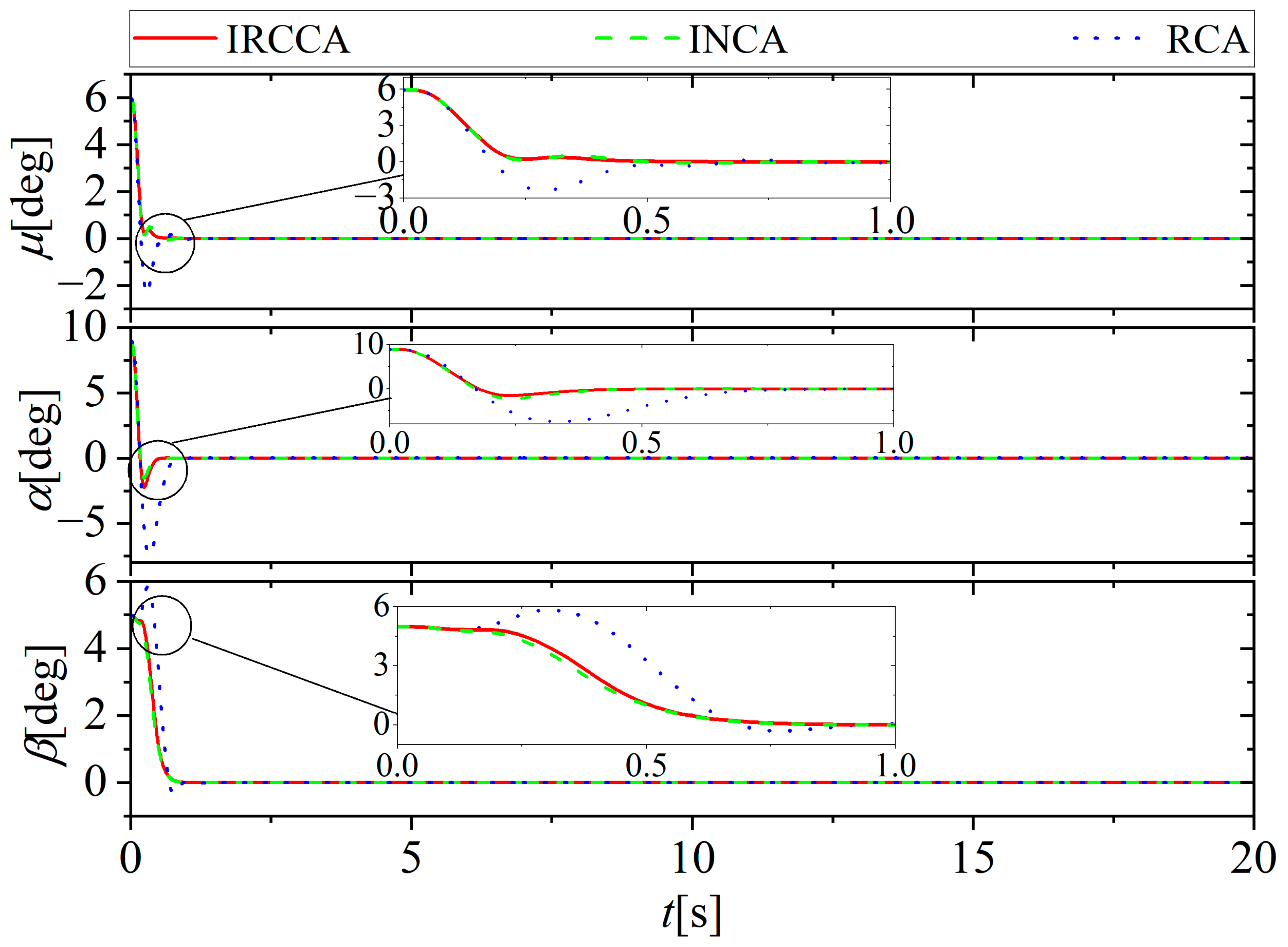
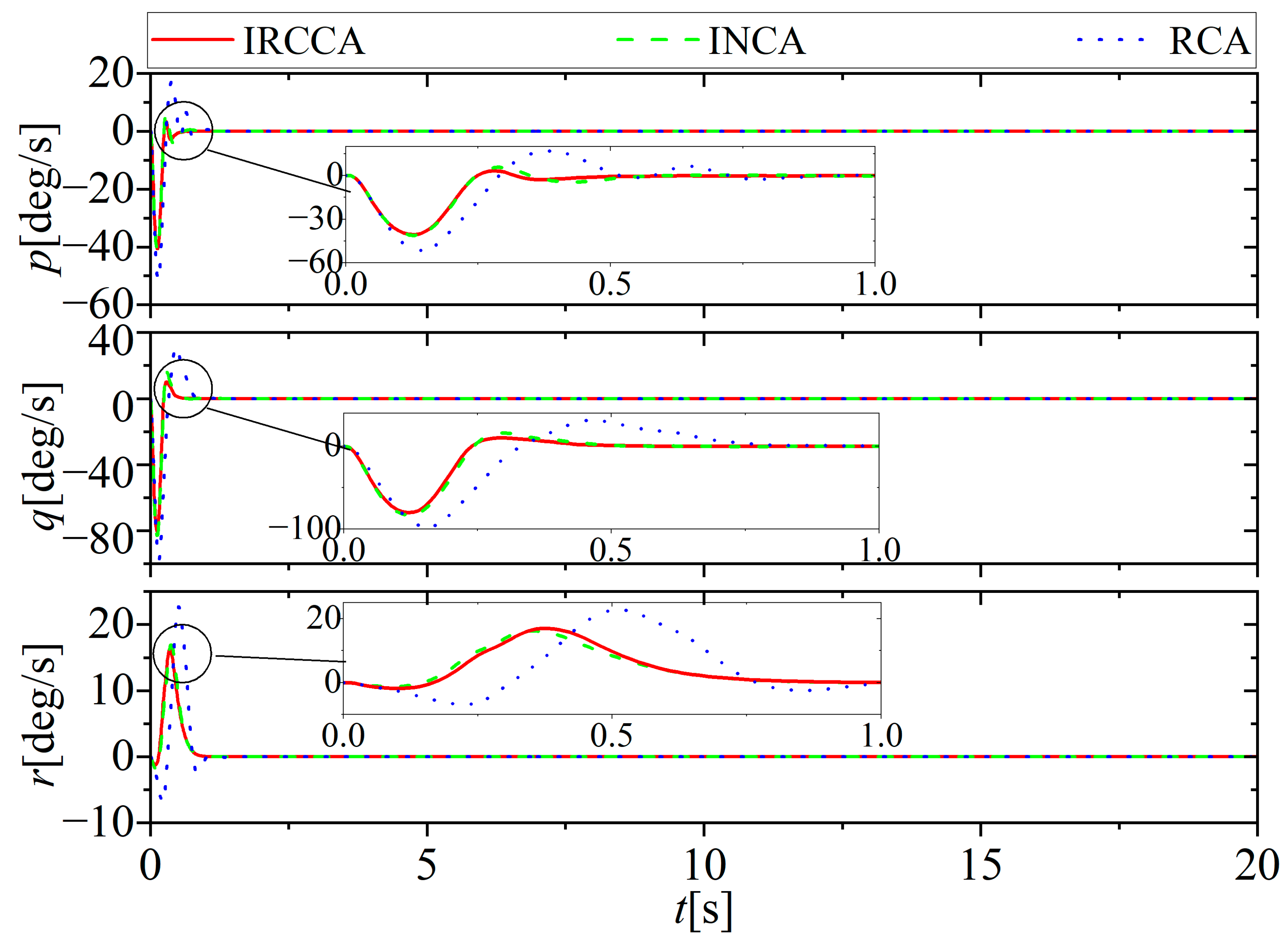
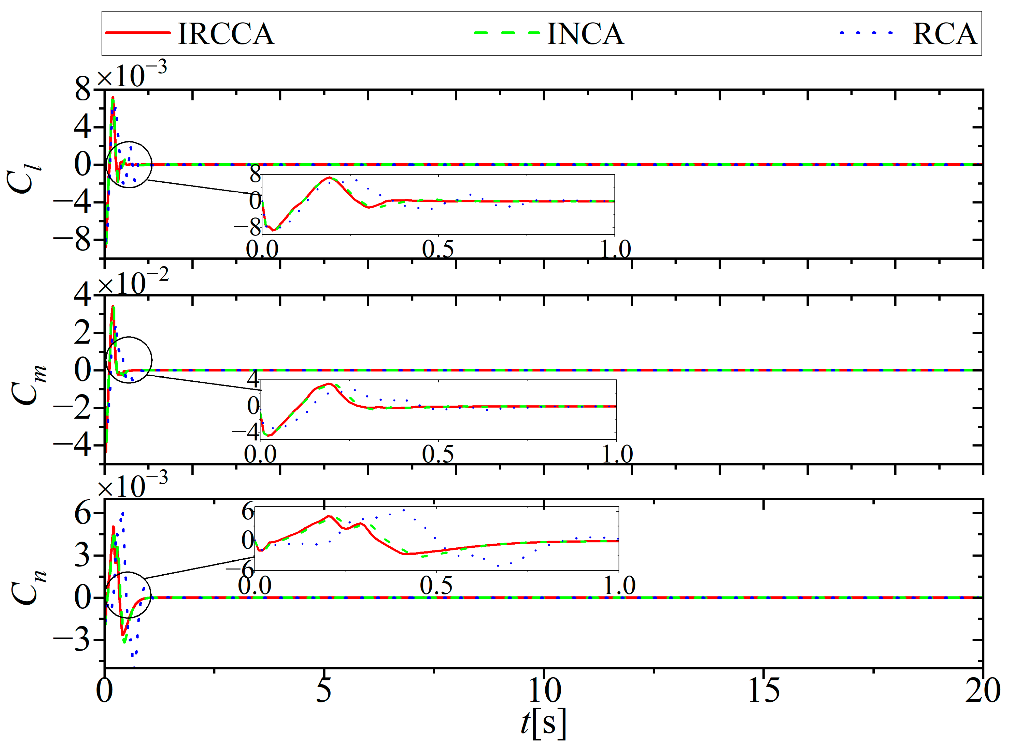
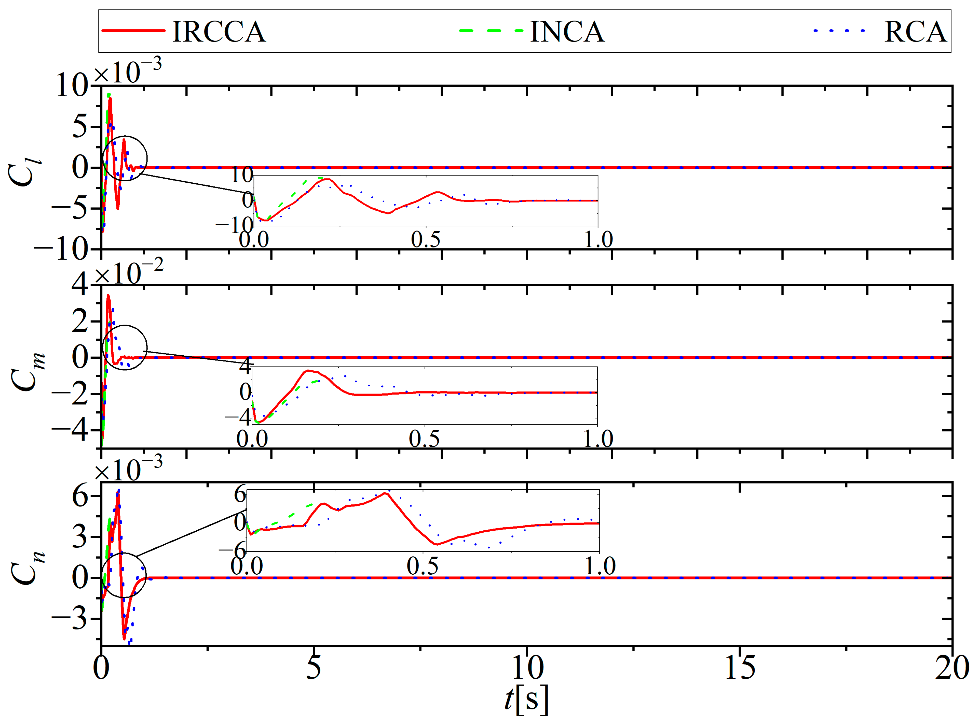
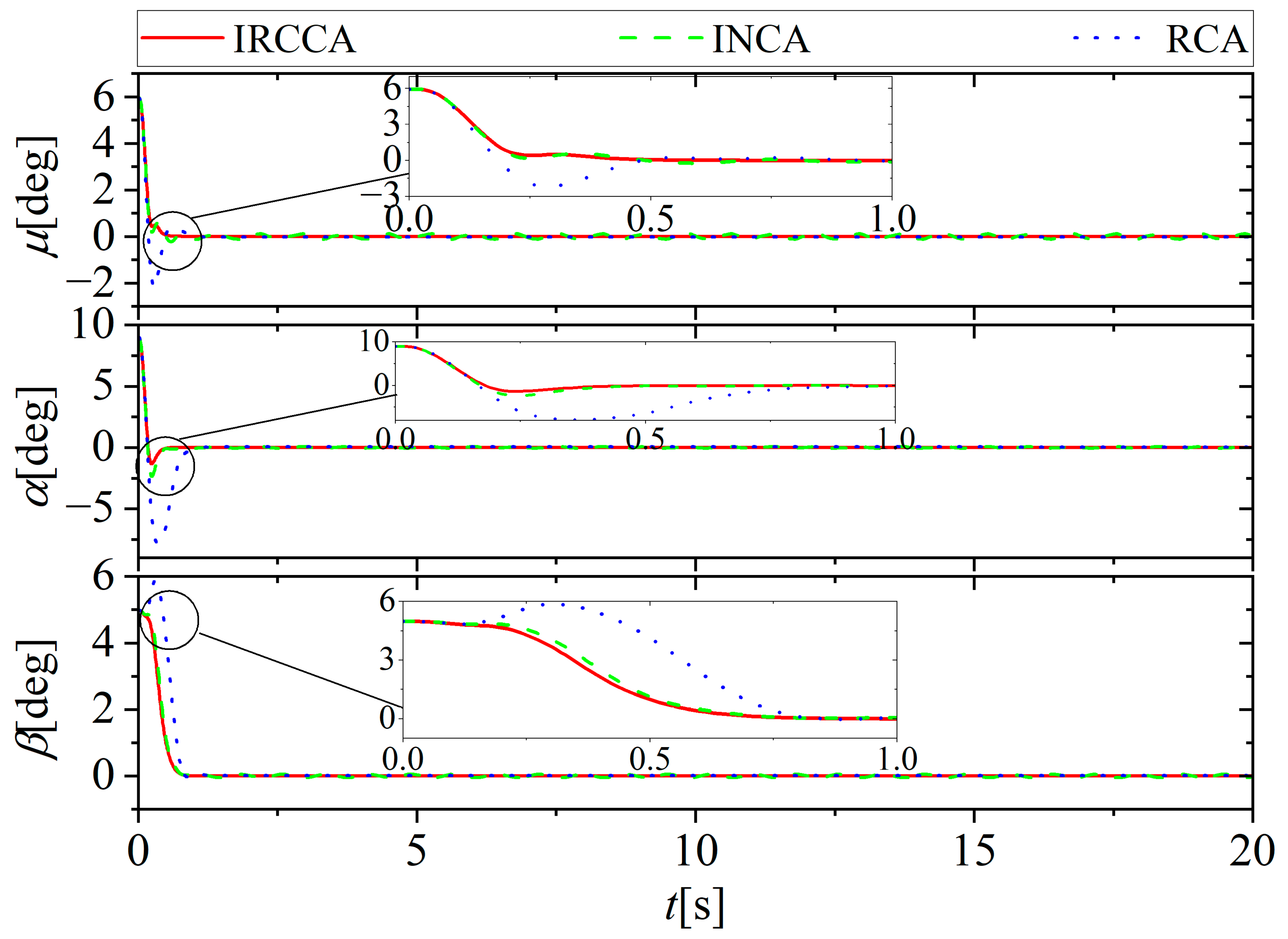
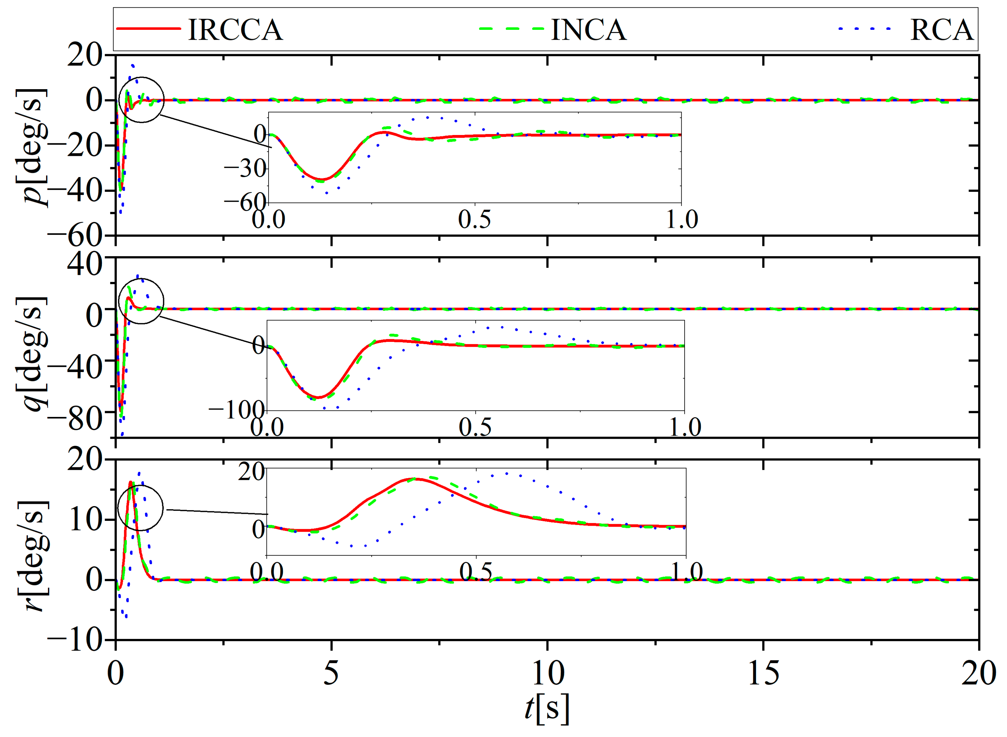
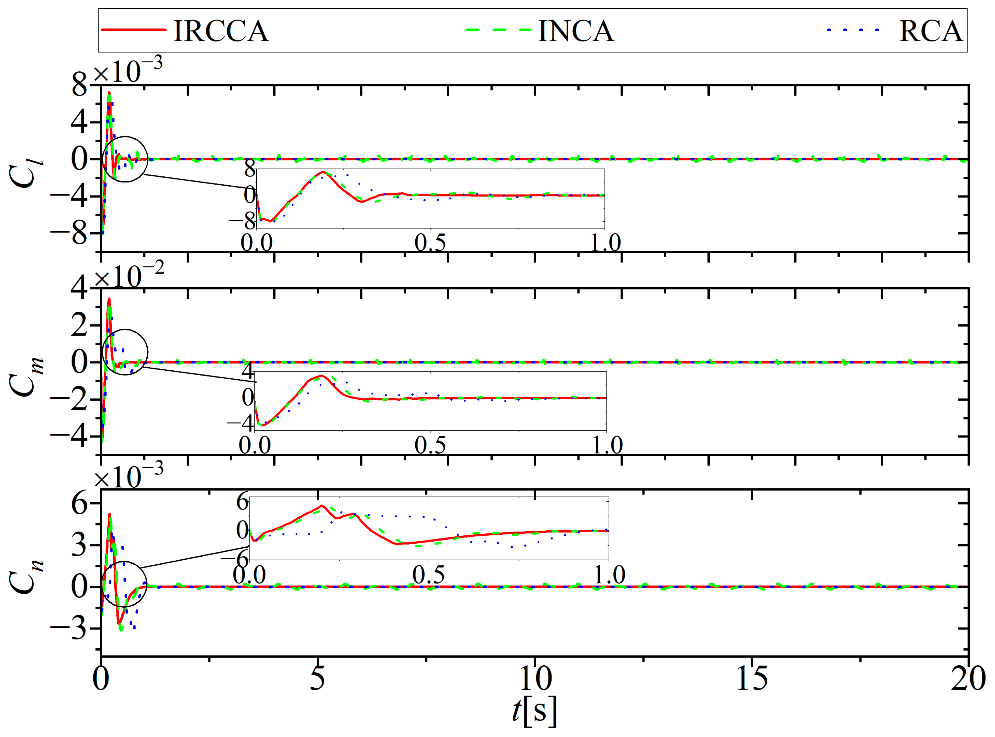
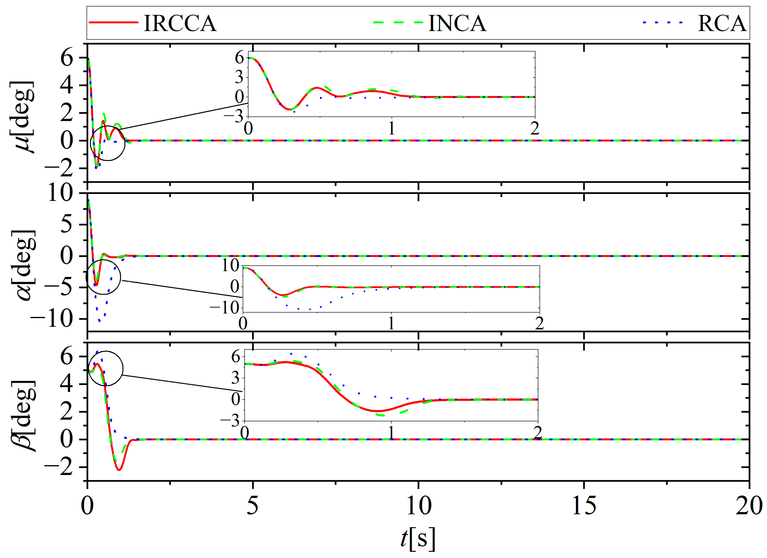
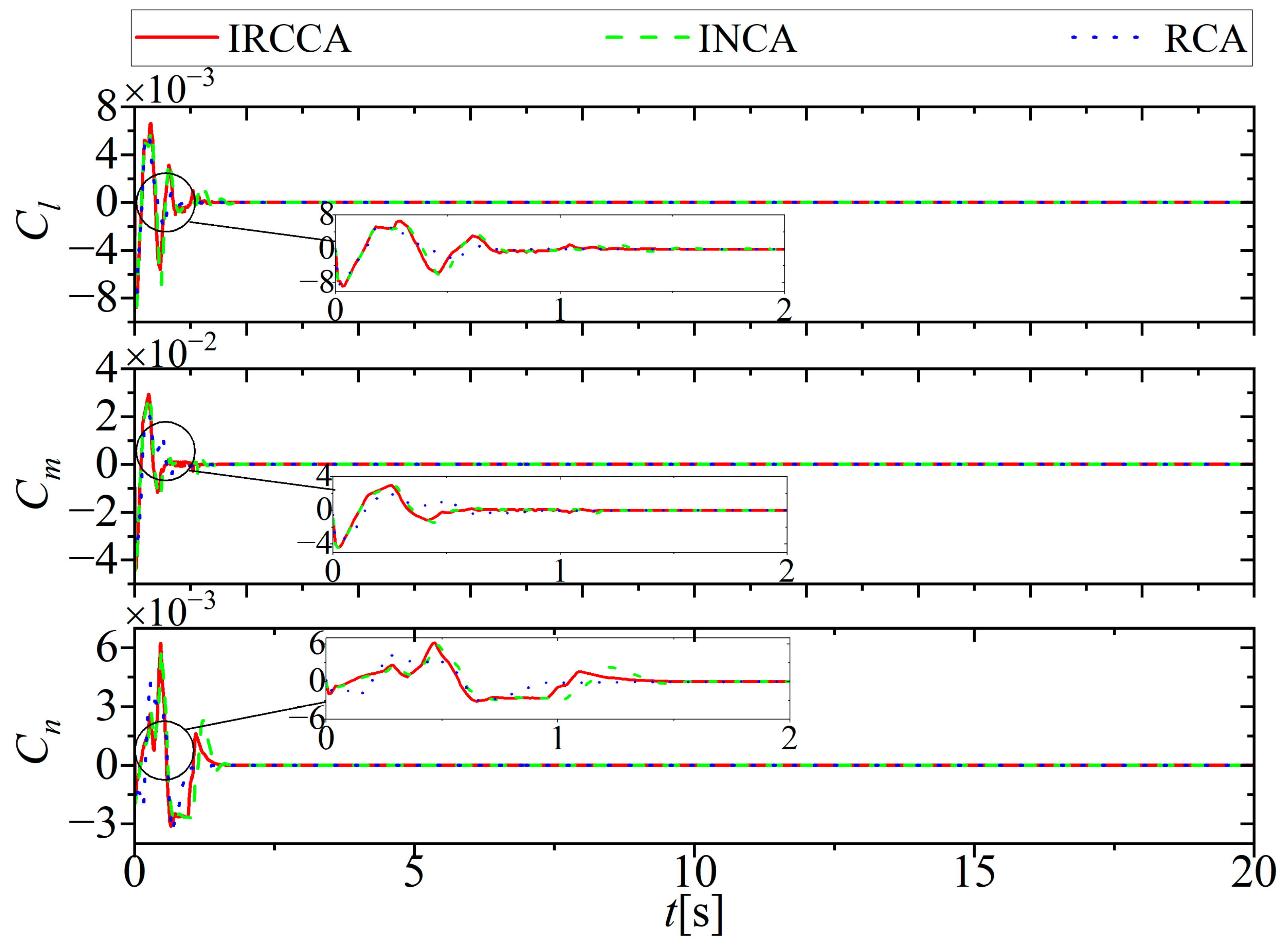
Firstly, the performances of methods are tested in the normal case. The attitude angle, the attitude angle rate, and the moment coefficient gained by the three methods are shown in Figure 2, Figure 3 and Figure 4. Figure 2 shows that there is a bigger overshot and a longer settling time for the RCA method. It is because the RCA uses the fixed effectiveness matrix to allocate the virtual command, which ignores the nonlinear relationship between the actuator deflection and their generated moment. Moreover, in contrast to INCA method, there is a smaller overshot for the IRCCA method. It is because with the distribution error feedback loop, the uncertainty of the control effectiveness matrix is compensated, and the distribution of the virtual command can be more accurate than INCA. Figure 3 shows that all attitude angle rates met the limitation and the changes in amplitude in IRCCA and INCA are smaller than that in RCA. Figure 4 shows that the change in the moment coefficient in RCA always lags behind INCA and IRCCA. With consideration of nonlinear characteristics, INCA and IRCCA can generate an accurate moment coefficient according to the virtual command. Conversely, RCA can only compensate for the error by the outer control loop. In view of these results, as it can be observed all three methods can make the system stable and the IRCCA achieves the best performance to enforce the attitude system to be stable. Table 5 shows the actual simulation time with the three methods. It can be seen that the three methods meet the real-time requirement. Moreover, the simulation time with RCA is less than the other two methods. It is because RCA saves computation time by applying the fixed control effectiveness matrix, whereas the INCA and IRCCA need to compute and gain the control effectiveness matrix in real-time.

5.2. Lock-in-Place Fault

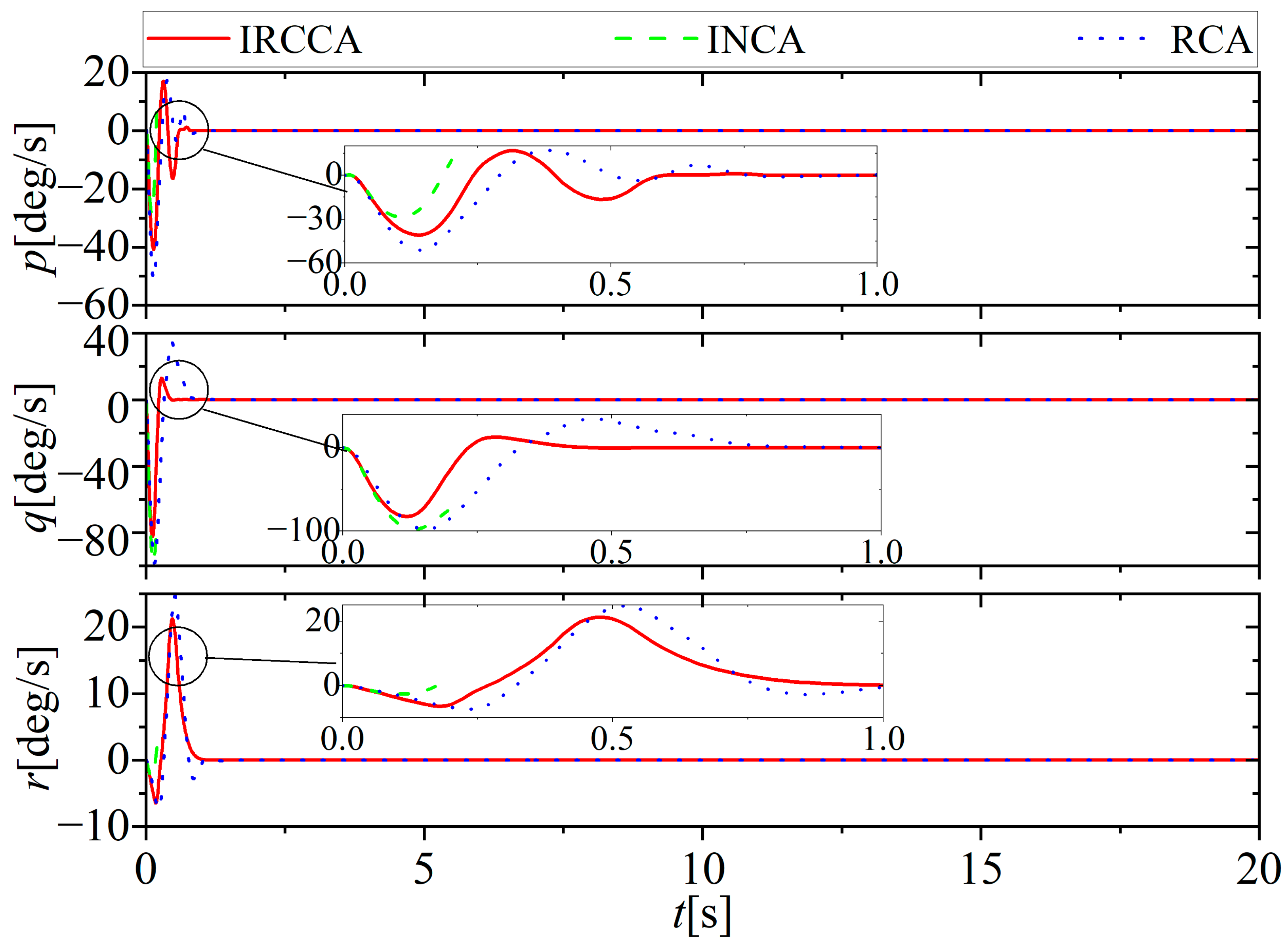
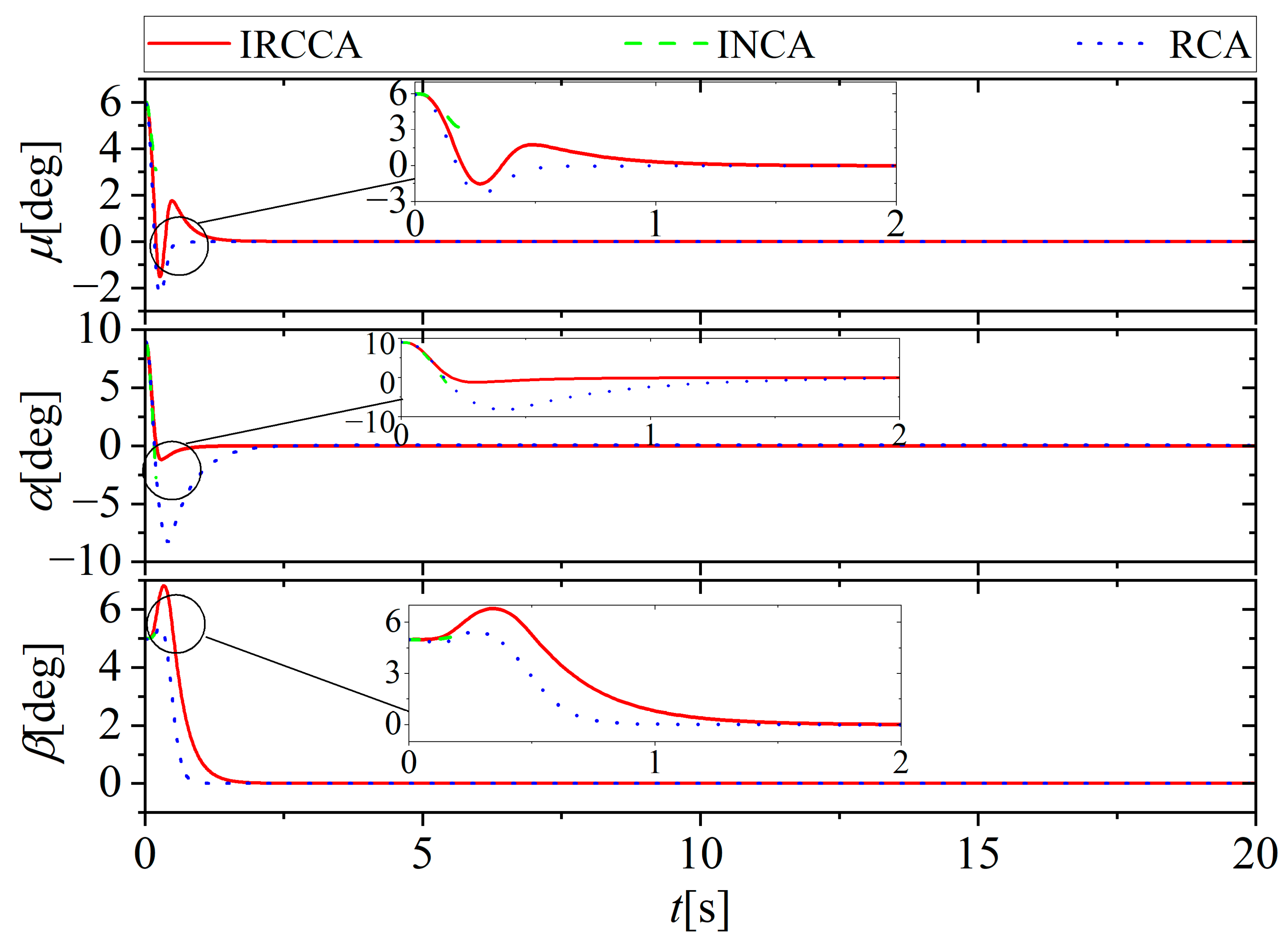
The performances of methods are tested with lock-in-place fault. The left elevon is stuck at 15 deg. The attitude angle, the attitude angle rate, and the moment coefficient gained by the three methods are shown in Figure 5, Figure 6 and Figure 7. As can be observed the INCA cannot maintain the system stability without the fault information. In contrast, IRCCA and RCA can still maintain the stability of the system. Moreover, there is a smaller overshot for IRCCA than RCA. Figure 8 shows the expected control output δ le gained by the three methods. It can be seen that IRCCA and INCA can identify the accuracy of the fault information, whereas the δ le gained by the RCA cannot be stable. In view of these results, one can assume that the proposed IRCCA scheme makes a better performance to deal with the lock-in-place fault than the other two methods.

5.3. Loose Fault

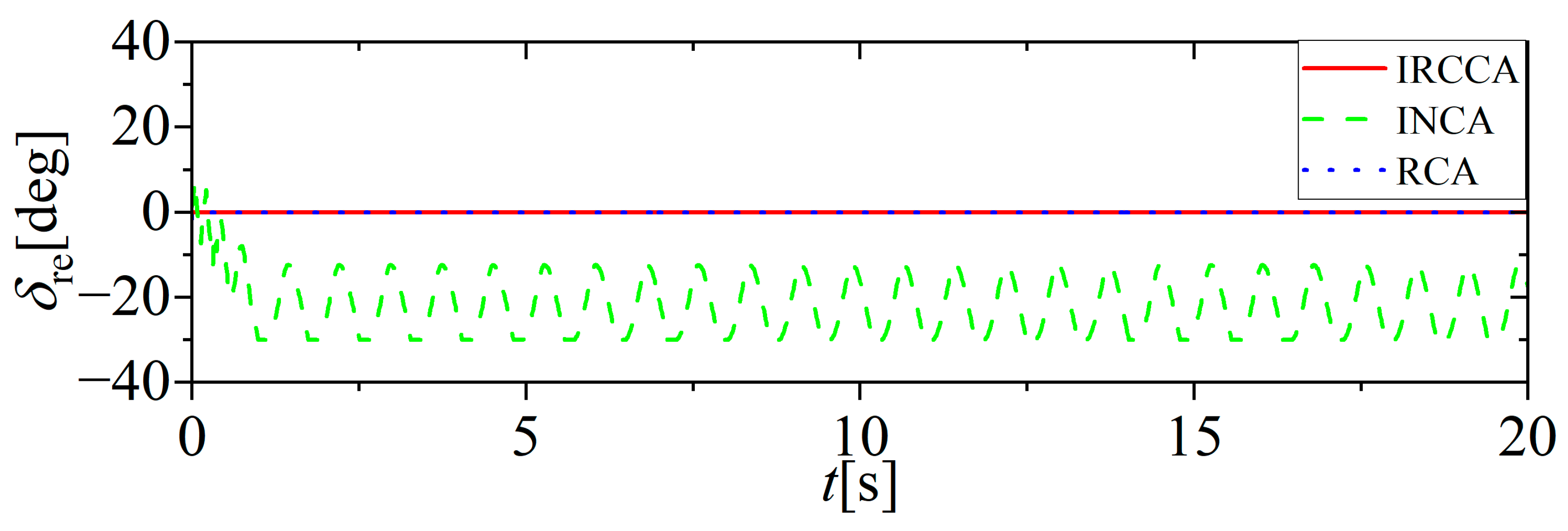
The performances of the methods are tested with the loose fault. It is assumed that the right elevon has a loose fault. The attitude angle, the attitude angle rate, and the moment coefficient gained by the three methods are shown in Figure 9, Figure 10 and Figure 11. As can be observed the output of INCA presents a chattering phenomenon. In contrast, IRCCA and RCA can still maintain the stability of the system. Moreover, there is a smaller overshot for IRCCA than RCA. Figure 12 shows the expected control output δ re gained by the three methods. It can be seen that IRCCA and INCA can identify the accuracy of the fault information, whereas the δ re gained by the RCA cannot be stable. In view of these results, one can obtain that the proposed IRCCA scheme makes a better performance to deal with the loose fault than the other two methods.

5.4. Loss of Effectiveness Fault

The performances of the methods are tested with the loss of effectiveness fault. It is assumed that the right SSD has a 50% loss of effectiveness fault. The attitude angle, the attitude angle rate, and the moment coefficient gained by the three methods are shown in Figure 13, Figure 14 and Figure 15. As can be observed the three methods can maintain the stability of the system. The tracking performance of INCA is almost the same as IRCCA. It is because the loss of effectiveness fault just changes the control effectiveness matrix, and does not instantaneously change the actuator deflections. Due to the high robustness against the change of control effectiveness matrix, the INCA can also attain a superior performance to deal with the loss of effectiveness fault. Figure 16 shows the expected control output δ rssd gained by the three methods. It can be seen that the expected control output δ rssd gained by RCA is different from INCA and IRCCA. This different distribution result is caused by the different CA methods. In view of these results, one can assume that the INCA and the proposed IRCCA make better performance to deal with the loss of effectiveness fault than the RCA methods.

5.5. Multiple Faults

Finally, the fault case is considered under a complex and harsh situation: the left elevon is stuck at 15 deg, the right elevon has loose fault, and the right SSD has a 50% loss of effectiveness fault.
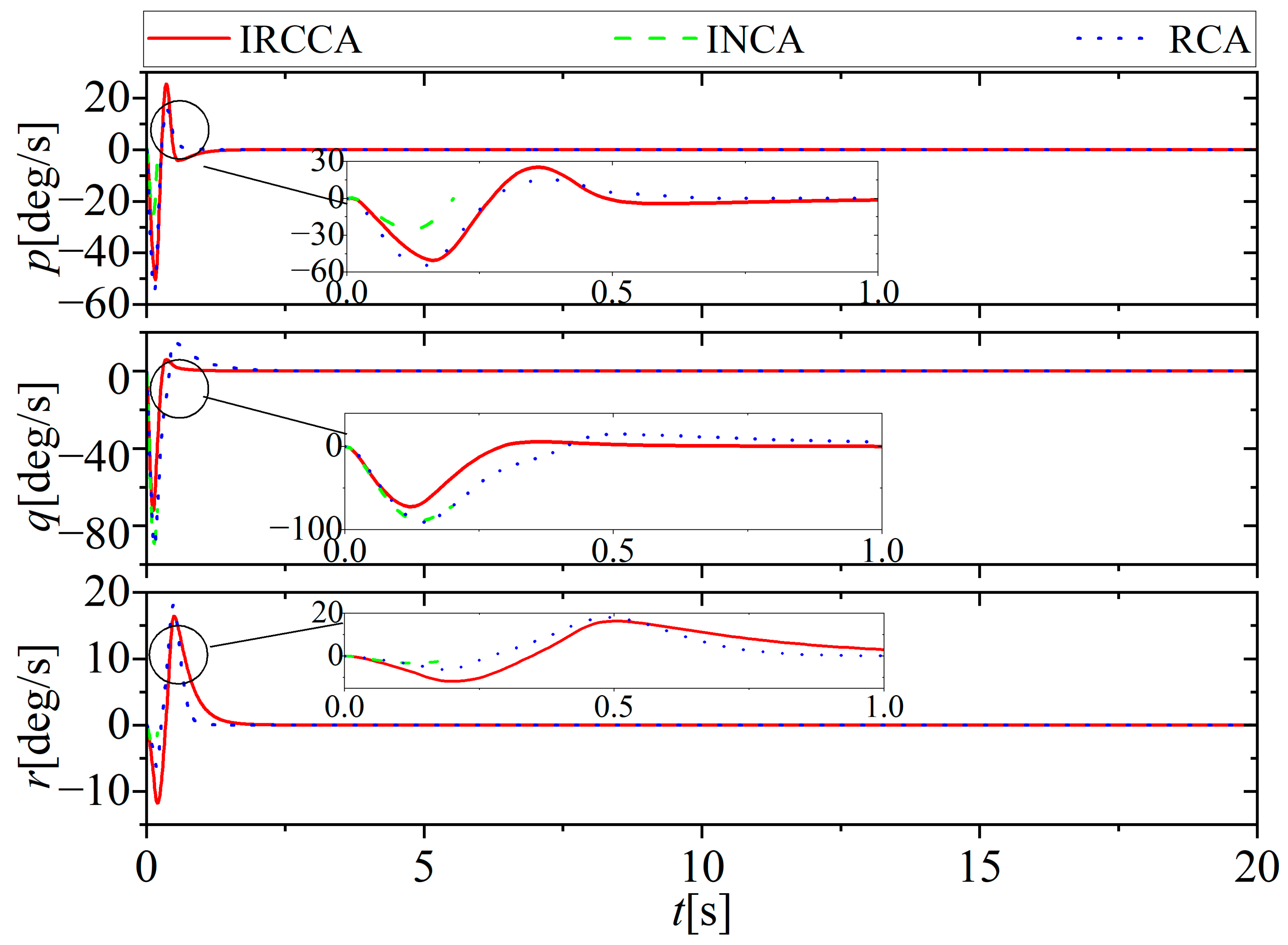
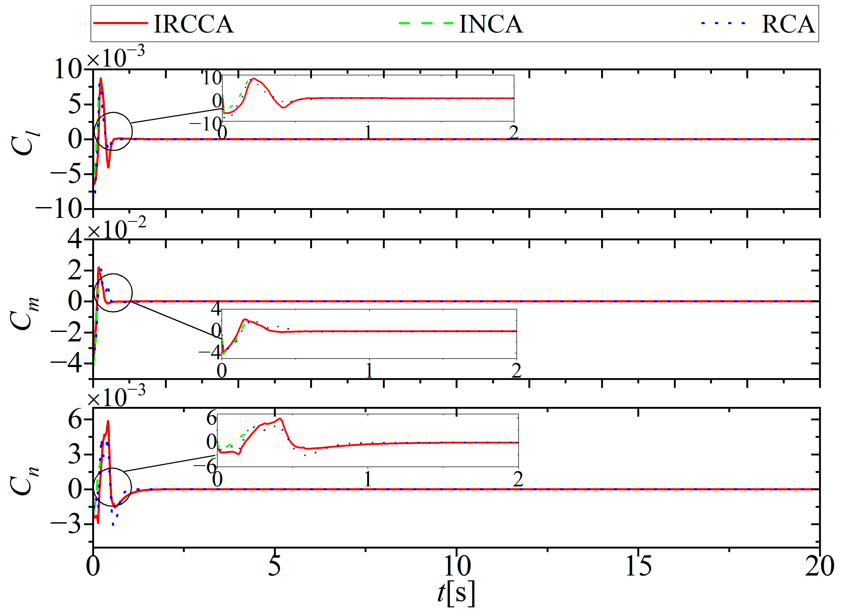
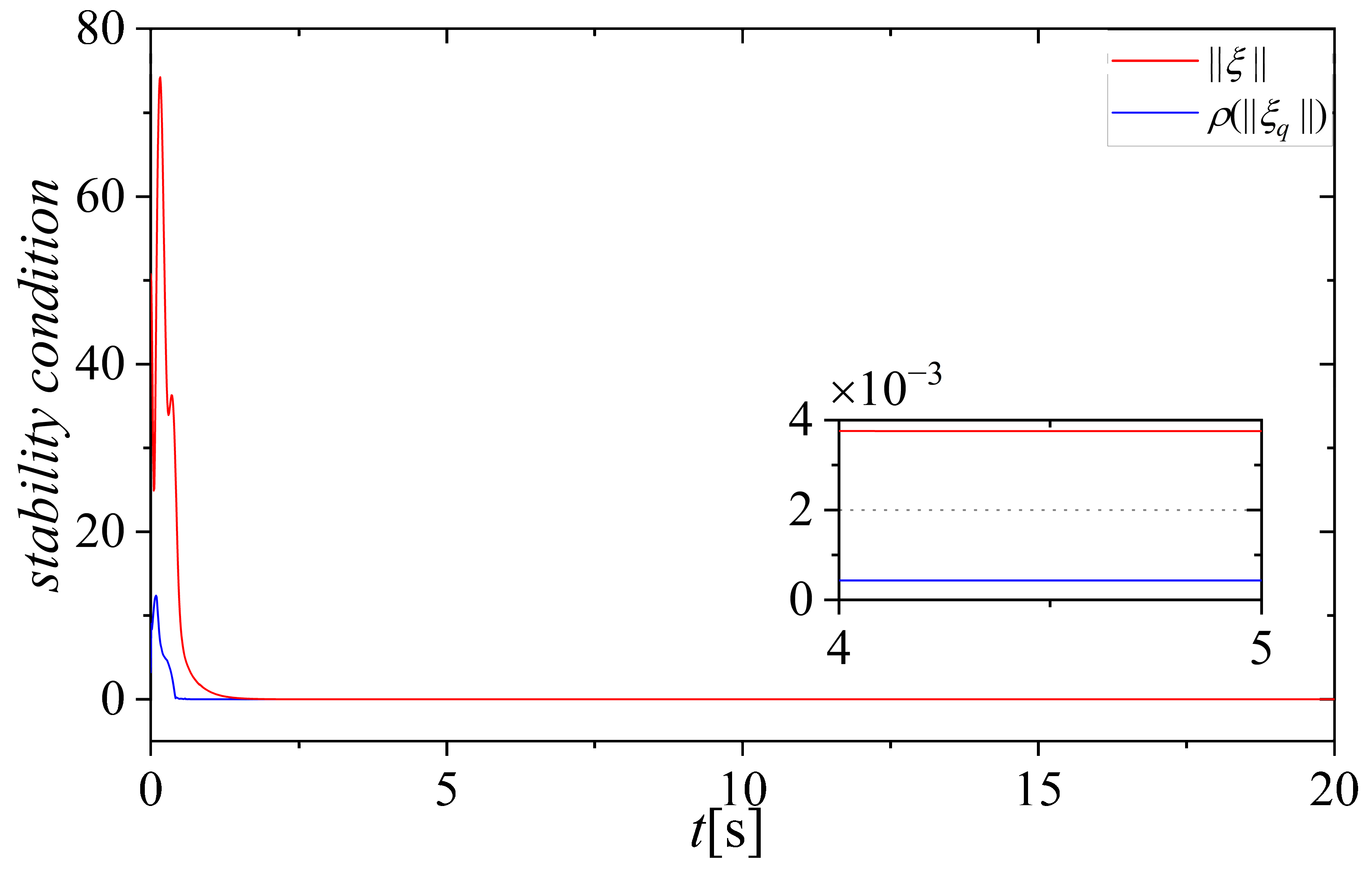
The attitude angle, the attitude angle velocity, and the moment coefficient gained by the four methods are shown in Figure 17, Figure 18 and Figure 19. As can be observed the IRCCA achieves the best performance to enforce the attitude system to be stable, whereas the INCA cannot maintain stability under the severe situation. The effectiveness of the reconfiguration design can be seen by the comparison. Moreover, there is a smaller overshot in pitch command for IRCCA contrasting with RCA, which also demonstrates the superiority of the proposed method. It can be seen in Figure 20 that the stability condition of the control system | | ξ | | ρ ( | | ξ q | | ) is satisfied throughout the whole process. As what is expected, the IRCCA successfully compensates the actuator fault with the fault information.

6. Conclusions

In this paper, an incremental reconfiguration closed-loop control allocation is proposed for supersonic tailless aircraft attitude control with actuator faults. With a closed-loop distribution error feedback design in the INCA, the nonlinear control allocation problem is transformed into an incremental form and the uncertainty is compensated. Utilizing the fault information, the control allocation matrix is reconfigured to ensure that the control system can deal with the actuator fault. With a basic backstepping attitude controller, the attitude control of supersonic tailless aircraft is achieved. Numerical simulation results illustrate that the proposed scheme can guarantee that the closed-loop system is stable, achieves accurate command tracking in the presence of actuator faults, and has better performance than the existing methods. Hence, the IRCCA achieves a more convenient design and better performance than the traditional FTC. However, the control input in this paper does not consider the multi-axis thrust vectoring. This paper mainly focuses on the nonlinearity and uncertainty of the control effectiveness matrix and the actuator fault. Severe external disturbance is not considered. Therefore, the robust control containing the multi-axis thrust vectoring towards severe external disturbance will be the focus of our future research.

Author Contributions

Conceptualization, J.C. and Y.W.; methodology, J.H.; software, J.C.; validation, Z.H., M.S. and L.H.; formal analysis, J.C.; investigation, M.S.; resources, L.H.; data curation, Y.W.; writing—original draft preparation, J.C.; writing—review and editing, Y.W.; visualization, J.C.; supervision, J.H.; project administration, Y.W.; funding acquisition, Y.W. All authors have read and agreed to the published version of the manuscript.

Funding

This work was supported by the National Natural Science Foundation of China [grant number 62103439], China Postdoctoral Science Foundation [grant number 2020M683716] and Natural Science Basic Research Program of Shaanxi Province [grant number 2021JQ-364].

Data Availability Statement

Not applicable.

Acknowledgments

Our sincere appreciation goes to the Editors and Reviewers for their good insights to brush up the technical notes.

Conflicts of Interest

The authors declare no conflict of interest.

References

  1. Niestroy, M.A.; Dorsett, K.M.; Markstein, K. A tailless fighter aircraft model for control-related research and development. In Proceedings of the AIAA Modeling and Simulation Technologies Conference, Grapevine, TX, USA, 9–13 January 2017. [Google Scholar]
  2. Hou, Y.; Lv, M.; Liang, X.; Yang, A. Fuzzy adaptive fixed-time fault-tolerant attitude tracking control for tailless flying wing aircrafts. Aerosp. Sci. Technol. 2022, 130, 107950. [Google Scholar] [CrossRef]
  3. Li, H.; Sun, L.; Tan, W.; Liu, X.; Dang, W. Incremental dual heuristic dynamic programming based hybrid approach for multi-channel control of unstable tailless aircraft. IEEE Access 2022, 10, 31677–31691. [Google Scholar] [CrossRef]
  4. He, Z.; Hu, J.; Wang, Y.; Cong, J.; Han, L.; Su, M. Sample entropy based prescribed performance control for tailless aircraft. ISA Trans. 2022, 131, 349–366. [Google Scholar] [CrossRef]
  5. He, Z.; Hu, J.; Wang, Y.; Cong, J.; Han, L.; Su, M. Incremental Backstepping Sliding-Mode Trajectory Control for Tailless Aircraft with Stability Enhancer. Aerospace 2022, 9, 352. [Google Scholar] [CrossRef]
  6. Shayan, K.; Van Kampen, E.-J. Online Actor-Critic-Based Adaptive Control for a Tailless Aircraft with Innovative Control Effectors. In Proceedings of the AIAA Scitech 2021 Forum, Online, 11–15 and 19–21 January 2021. [Google Scholar] [CrossRef]
  7. Harris, J.; Elliott, C.M.; Tallant, G.S. L1 Adaptive Nonlinear Dynamic Inversion Control for the Innovative Control Effectors Aircraft. In Proceedings of the AIAA Scitech 2022 Forum, San Diego, CA, USA, 3–7 January 2022. [Google Scholar] [CrossRef]
  8. Cai, W.; Liao, X.H.; Song, Y.D. Indirect Robust Adaptive Fault-Tolerant Control for Attitude Tracking of Spacecraft. J. Guid. Control Dyn. 2008, 31, 1456–1463. [Google Scholar] [CrossRef]
  9. Chen, T.; Chen, L.; Xu, X.; Cai, Y.; Jiang, H.; Sun, X. Passive fault-tolerant path following control of autonomous distributed drive electric vehicle considering steering system fault. Mech. Syst. Signal Process. 2019, 123, 298–315. [Google Scholar] [CrossRef]
  10. Zhu, G.; Du, J.; Li, J.; Kao, Y. Robust adaptive NN tracking control for MIMO uncertain nonlinear systems with completely unknown control gains under input saturations. Neurocomputing 2019, 365, 125–136. [Google Scholar] [CrossRef]
  11. Yazar, I.; Caliskan, F.; Kiyak, E. Multiple fault-based FDI and reconfiguration for aircraft engine sensors. Aircr. Eng. Aerosp. Technol. 2017, 89, 397–405. [Google Scholar] [CrossRef]
  12. Kilic, U.; Unal, G. Sensor fault detection and reconstruction system for commercial aircrafts. Aeronaut. J. 2022, 126, 889–905. [Google Scholar] [CrossRef]
  13. Unal, G. Fuzzy robust fault estimation scheme for fault tolerant flight control systems based on unknown input observer. Aircr. Eng. Aerosp. Technol. 2021, 93, 1624–1631. [Google Scholar] [CrossRef]
  14. Kilic, U.; Unal, G. Aircraft air data system fault detection and reconstruction scheme design. Aircr. Eng. Aerosp. Technol. 2021, 93, 1104–1114. [Google Scholar] [CrossRef]
  15. Li, B.; Hu, Q.; Ma, G.; Yang, Y. Fault-Tolerant Attitude Stabilization Incorporating Closed-Loop Control Allocation Under Actuator Failure. IEEE Trans. Aerosp. Electron. Syst. 2018, 55, 1989–2000. [Google Scholar] [CrossRef]
  16. Li, Y.; Hou, M.; Liang, S.; Jiao, G. Predefined-time adaptive fault-tolerant control of hypersonic flight vehicles without overparameterization. Aerosp. Sci. Technol. 2020, 104, 105987. [Google Scholar] [CrossRef]
  17. Unal, G. Integrated design of fault-tolerant control for flight control systems using observer and fuzzy logic. Aircr. Eng. Aerosp. Technol. 2021, 93, 723–732. [Google Scholar] [CrossRef]
  18. Zhang, S.; Huang, C.; Ji, K.; Zhang, H. Prescribed performance incremental adaptive optimal fault-tolerant control for nonlinear systems with actuator faults. ISA Trans. 2022, 120, 99–109. [Google Scholar] [CrossRef]
  19. Cui, L.; Zuo, Z.; Yang, Y. A Control-Theoretic Study on Iterative Solution to Control Allocation for Over-Actuated Aircraft. IEEE Trans. Syst. Man Cybern. Syst. 2019, 51, 3429–3439. [Google Scholar] [CrossRef]
  20. Su, Y.; Yu, P.; Gerber, M.J.; Ruan, L.; Tsao, T.-C. Nullspace-Based Control Allocation of Overactuated UAV Platforms. IEEE Robot. Autom. Lett. 2021, 6, 8094–8101. [Google Scholar] [CrossRef]
  21. Yang, Y.; Gao, Z. A New Method for Control Allocation of Aircraft Flight Control System. IEEE Trans. Autom. Control 2020, 65, 1413–1428. [Google Scholar] [CrossRef]
  22. Tohidi, S.S.; Yildiz, Y.; Kolmanovsky, I. Adaptive control allocation for constrained systems. Automatica 2020, 121, 109161. [Google Scholar] [CrossRef]
  23. de Almeida, F.A. Robust off-line control allocation. Aerosp. Sci. Technol. 2016, 52, 1–9. [Google Scholar] [CrossRef]
  24. Servidia, P.; Pena, R. Spacecraft thruster control allocation problems. IEEE Trans. Autom. Control 2005, 50, 245–249. [Google Scholar] [CrossRef]
  25. Oppenheimer, M.W.; Doman, D.B.; Bolender, M.A. Control Allocation for Over-actuated Systems. In Proceedings of the 14th Mediterranean Conference on Control and Automation, Ancona, Italy, 28–30 June 2006; pp. 1–6. [Google Scholar]
  26. Harkegard, O. Efficient active set algorithms for solving constrained least squares problems in aircraft control allocation. In Proceedings of the 41st IEEE Conference on Decision and Control, Las Vegas, NV, USA, 10–13 December 2002; Volume 2, pp. 1295–1300. [Google Scholar]
  27. Luo, Y.; Serrani, A.; Yurkovich, S.; Doman, D.; Oppenheimer, M.W. Model predictive dynamic control allocation with actuator dynamics. In Proceedings of the 2004 American Control Conference, Boston, MA, USA, 30 June–2 July 2004; Volume 2, pp. 1695–1700. [Google Scholar] [CrossRef]
  28. Galeani, S.; Sassano, M. Data-driven dynamic control allocation for uncertain redundant plants. In Proceedings of the 2018 IEEE Conference on Decision and Control (CDC), Miami Beach, FL, USA, 17–19 December 2018; pp. 5494–5499. [Google Scholar]
  29. Naderi, M.; Sedigh, A.K.; Johansen, T.A. Guaranteed feasible control allocation using model predictive control. Control Theory Technol. 2019, 17, 252–264. [Google Scholar] [CrossRef]
  30. Elsisi, M.; Zaini, H.G.; Mahmoud, K.; Bergies, S.; Ghoneim, S.S. Improvement of Trajectory Tracking by Robot Manipulator Based on a New Co-Operative Optimization Algorithm. Mathematics 2021, 9, 3231. [Google Scholar] [CrossRef]
  31. Elsisi, M.; Tran, M.Q. Development of an IoT Architecture Based on a Deep Neural Network against Cyber Attacks for Automated Guided Vehicles. Sensors 2021, 21, 8467. [Google Scholar] [CrossRef]
  32. Gai, W.; Wang, H. Closed-loop dynamic control allocation for aircraft with multiple actuators. Chin. J. Aeronaut. 2013, 26, 676–686. [Google Scholar] [CrossRef] [Green Version]
  33. Hu, Q.; Li, B.; Zhang, Y. Nonlinear proportional derivative control incorporating closed-loop control allocation for spacecraft. J. Guid. Control Dyn. 2014, 37, 799–812. [Google Scholar] [CrossRef]
  34. Chen, L.; Duan, D.; Sun, D. Design of a multi-vectored thrust aerostat with a reconfigurable control system. Aerosp. Sci. Technol. 2016, 53, 95–102. [Google Scholar] [CrossRef] [Green Version]
  35. Almutairi, S.H.; Aouf, N. Reconfigurable dynamic control allocation for aircraft with actuator failures. Aeronaut. J. 2017, 121, 341–371. [Google Scholar] [CrossRef]
  36. Ergocmen, B. Reconfigurable Dynamic Control Allocation with SDRE As a FTFC for NASA GTM Design. In Proceedings of the 2021 American Control Conference (ACC), New Orleans, LA, USA, 25–28 May 2021. [Google Scholar]
  37. Doman, D.; Sparks, A. Concepts for constrained control allocation of mixed quadratic and linear effectors. In Proceedings of the 2002 American control conference, Anchorage, AK, USA, 8–10 May 2002; Volume 5, pp. 3729–3734. [Google Scholar]
  38. Poonamallee, V.; Yurkovich, S.; Serrani, A.; Doman, D.; Oppenheimer, M.W. A nonlinear programming approach for control allocation. In Proceedings of the 2004 American Control Conference, Boston, MA, USA, 30 June–2 July 2004; pp. 1689–1694. [Google Scholar] [CrossRef]
  39. Bolender, M.A.; Doman, D.B. Nonlinear Control Allocation Using Piecewise Linear Functions. J. Guid. Control Dyn. 2004, 27, 1017–1027. [Google Scholar] [CrossRef] [Green Version]
  40. Tol, H.J.; De Visser, C.C.; Van Kampen, E.; Chu, Q.P. Nonlinear Multiariate spline-based control allocation for high-performance aircraft. J. Guid. Control Dyn. 2014, 37, 1840–1862. [Google Scholar] [CrossRef] [Green Version]
  41. Matamoros, I. Incremental Nonlinear Control Allocation for a Tailless Aircraft with Innovative Control Effectors. Master’s Thesis, Delft University of Technology, Delft, The Netherlands, 2017. [Google Scholar]
  42. Tang, X.; Zhai, D.; Li, X. Adaptive fault-tolerance control based finite-time backstepping for hypersonic flight vehicle with full state constrains. Inf. Sci. 2019, 507, 53–66. [Google Scholar] [CrossRef]
  43. Yu, Z.; Li, Y.; Lv, M.; Chang, J.; Pei, B. Predefined-time anti-saturation fault-tolerant attitude control for tailless aircraft with guaranteed output constraints. Nonlinear Dyn. 2022, 111, 1399–1416. [Google Scholar] [CrossRef]
  44. Cui, Y.; Li, A.; Duan, B.; Wasif, S. Reconfiguration Control Design of UAV against Actuator Faults Based on Control Allocation Method. Int. J. Aerosp. Eng. 2022, 2022, 4481553. [Google Scholar] [CrossRef]
  45. Johann, K. Advanced Flight Control Design And evaluation: An Application of Time Delayed Incremental Backstepping. Master’s Thesis, Delft University of Technology, Delft, The Netherlands, 2012. [Google Scholar]
  46. Smeur, E.J.; Chu, Q.P.; de Croon, G.C. Adaptive Incremental Nonlinear Dynamic Inversion for Attitude Control of Micro Aerial Vehicles. J. Guid. Control Dyn. 2016, 39, 450–461. [Google Scholar] [CrossRef] [Green Version]
  47. Jury, E.I. A Simplified Stability Criterion for Linear Discrete Systems. Proc. IRE 1962, 50, 1493–1500. [Google Scholar] [CrossRef]
  48. Liberzon, D. Hybrid feedback stabilization of systems with quantized signals. Automatica 2003, 39, 1543–1554. [Google Scholar] [CrossRef]
  49. Stolk, A.J. Minimum Drag Control Allocation for the Innovative Control Effector Aircraft. Master’s Thesis, Delft University of Technology, Delft, The Netherlands, 2017. [Google Scholar]
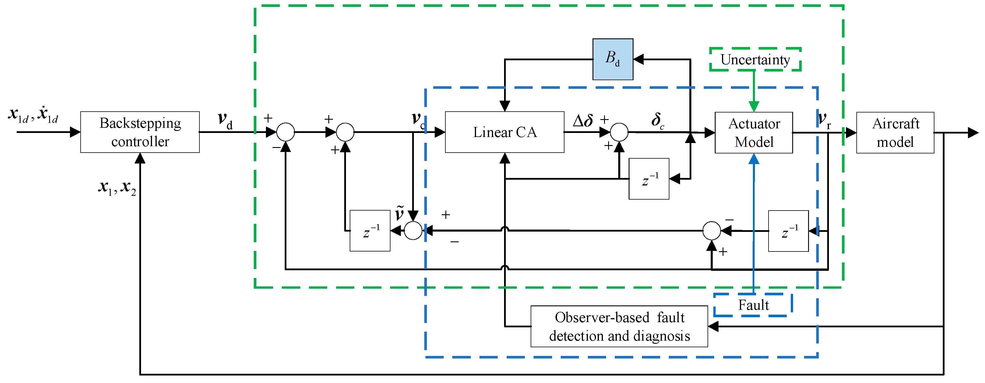
Figure 1. Fault-tolerant attitude control incorporating reconfiguration control allocation scheme.
Aerospace 10 00241 g001
Figure 2. Time response of the attitude angle with no actuator fault.
Aerospace 10 00241 g002
Figure 3. Time response of the attitude angle rate with no actuator fault.
Aerospace 10 00241 g003
Figure 4. Time response of the moment coefficient with no actuator fault.
Aerospace 10 00241 g004
Figure 5. Time response of the attitude angle with lock-in-place fault.
Aerospace 10 00241 g005
Figure 6. Time response of the attitude angle rate with lock-in-place fault.
Aerospace 10 00241 g006
Figure 7. Time response of the moment coefficient with lock-in-place fault.
Aerospace 10 00241 g007
Figure 8. Time response of the fault actuator δ le deflection.
Aerospace 10 00241 g008
Figure 9. Time response of the attitude angle with loose fault.
Aerospace 10 00241 g009
Figure 10. Time response of the attitude angle rate with loose fault.
Aerospace 10 00241 g010
Figure 11. Time response of the moment coefficient with loose fault.
Aerospace 10 00241 g011
Figure 12. Time response of the fault actuator δ re deflection.
Aerospace 10 00241 g012
Figure 13. Time response of the attitude angle with a loss of effectiveness fault.
Aerospace 10 00241 g013
Figure 14. Time response of the attitude angle rate with a loss of effectiveness fault.
Aerospace 10 00241 g014
Figure 15. Time response of the moment coefficient with a loss of effectiveness fault.
Aerospace 10 00241 g015
Figure 16. Time response of the fault actuator δ rssd deflection.
Aerospace 10 00241 g016
Figure 17. Time response of the attitude angle with multiple faults.
Aerospace 10 00241 g017
Figure 18. Time response of the attitude angle rate with multiple faults.
Aerospace 10 00241 g018
Figure 19. Time response of the moment coefficient with multiple faults.
Aerospace 10 00241 g019
Figure 20. Time response of the | | ξ | | and ρ ( | | ξ q | | ) in IRCCA with multiple faults.
Aerospace 10 00241 g020
Table 1. Wing planform and inertia parameters for the model.
ParameterValueParameterValue
b 37.5 [ft] I y y 81,903 [slug-ft2]
c ¯ 28.75 [ft] I z z 118,379 [slug-ft2]
S 808.6 [ft2] I x z −525 [slug-ft2]
I x x 42,576 [slug-ft2] I z x −525 [slug-ft2]
Table 2. The operation ranges of the angular rates and attitude angles.
ParameterThe Operation Range [deg]ParameterThe Operation Range [deg/s]
α [−5,30] p [−100,100]
β [−20,20] q [−100,100]
μ [−90,90] r [−100,100]
Table 3. Dynamic characteristics of the ICE control actuators.
Control ActuatorNotationPosition Limit
[deg]
Rate Limit
[deg/s]
Inboard leading-edge flap (ILEF) δ lilef , δ rilef [0,40]40
Outboard leading-edge flap (OLEF) δ l olef , δ rolef [−40,40]40
All moving wing tips (AMT) δ lamt , δ ramt [0,60]150
Elevons δ le , δ re [−30,30]150
Spoiler-slot deflectors (SSD) δ lssd , δ rssd [0,60]150
Pitch flaps (PF) δ pf [−30,30]150
Table 4. The parameters of actuator faults.
Fault MatrixParameters of Actuator Faults
E 1 e 14 = 1 , e 1 i = 0 , i 4
E 2 e 210 = 1 , e 2 i = 0 , i 10
E 3 e 311 = 0.5 , e 3 i = 0 , i 11
Table 5. The simulation time with no actuator fault.
MethodRCAINCAIRCCA
Simulation time8.796 s16.051 s16.771 s
Disclaimer/Publisher’s Note: The statements, opinions and data contained in all publications are solely those of the individual author(s) and contributor(s) and not of MDPI and/or the editor(s). MDPI and/or the editor(s) disclaim responsibility for any injury to people or property resulting from any ideas, methods, instructions or products referred to in the content.