Abstract
In this paper, we consider the relative motion of a follower spacecraft orbiting the Earth in a near circular orbit with respect to a leader spacecraft. The relative orbital motion-control problem of the follower spacecraft is studied here. In order to allow the follower spacecraft to succeed in its target orbital motion maneuver, we proposed a multi-objective optimization method to solve the relative orbital motion-control problem. Firstly, a Hill–Clohessy–Wiltshire equation was used to describe the continuous relative orbital motion-control system. Then, the system was discretized into a discrete system using numerical methods. Next, a multi-objective optimization model of the relative orbital motion-control problem was formulated. In the model, two objectives, i.e., the orbital motion error and the energy consumption, were minimized simultaneously. Furthermore, the ε-constraint method was used to solve the multi-objective optimization problem and the Pareto front, which demonstrates that the trade-off between the two objectives can be achieved. Finally, numerical experiments were carried out to validate the effectiveness of the proposed multi-objective optimization approach.
1. Introduction
With the development of space science and technology, many different types of spacecraft have been launched into the sky. Spacecraft are widely used in communication, navigation, and positioning; resource exploration; and space science exploration, etc. [1]. In recent years, a distributed array of small, low-cost, cooperative, and highly coordinated spacecraft has vigorously been pursued. Compared with large individual spacecraft, for these distributed spacecraft flying in formation, information collected by each spacecraft can be shared with the others in the formation via inter-spacecraft communication to allow for a more flexible onboard data-management scheme [2]. With the ability to transfer information and measurements between member spacecraft, a more effective utilization of available computing resources can be achieved by techniques such as distributed computing and system load balancing.
There are various methods to realize spacecraft formation flying, such as the leader–follower strategy [3], virtual structure approaches [4], and behavior-based methods [5]. Among different control techniques, the leader–follower strategy is the most commonly used since it has a hierarchical structure; i.e., in the leader–follower mode, each follower spacecraft is controlled in order to maintain its position and velocity in relation to a designated leader spacecraft, which flies along a predefined trajectory. Many studies related to spacecraft attitude control are based on this control strategy [6]. For example, Wang and Hadagegh [7] first applied this control strategy to control satellite attitude. Since then, many experts have studied satellite formations in the leader–follower mode. In [8], the authors applied a feedback control algorithm to solve the control law for satellite attitude control. In [9,10], the application of robust control in satellite group attitude control was investigated. In [11], a fast finite-time sliding mode control method was proposed for the attitude control problem of magnetically actuated satellite systems. A terminal sliding mode control approach as utilized in [12] for the global stability and robust attitude tracking problem of a near-polar orbit satellite subject to unknown disturbances and uncertainties. In [13], an adaptive, fuzzy, proportional–integral–derivative controller was designed for geostationary satellite attitude control. In [14], a linear time-variant model predictive control was designed to control a satellite with two reaction wheels. In addition, there are some studies that use GPS-based state estimation methods to realize spacecraft formation flight [15,16].
The spacecraft rendezvous-control problem of a follower spacecraft in leader–follower control mode has attracted considerable attention. Generally, in the rendezvous phase, the interest is in the relative motion between two spacecraft, where relative motion control includes relative orbit control and relative attitude control. In [17], angular velocity and attitude estimators were designed to deal with information delay. A relative attitude determination scheme and a relative attitude control system were developed based on line-of-sight observations between two spacecraft in [18]. In [19], the attitude-tracking problem was formulated as a nonlinear optimal control problem, after which the state-dependent Riccati equation controller and -D controller were developed. For the presence of kinematic couplings and model uncertainties, a robust adaptive-relative position and relative attitude controllers were designed in [20]. In [21], for a non-cooperative target spacecraft fly-around mission, a modified nonsingular fast terminal sliding mode with bounded convergence time, regardless of the initial state, was designed. In [22], a relative motion-control algorithm that achieved robustness against external disturbances with less measurement information was proposed. For the relative attitude tracking of rigid spacecraft with disturbance torques on a target and a follower, a computationally tractable method leveraging sum-of-squares optimization was proposed in [23].
In the above methods, most of them are traditional control methods. They either only consider a single objective (i.e., orbital motion error) or consider both orbital motion error and energy consumption at the same time but often use a weighted sum strategy to transform the two-objective problem into a single-objective optimization problem. These methods can obtain only one control scheme. They did not consider the tradeoff between the orbital motion error and energy consumption and cannot provide decision makers with more choices in the case of different task requirements.
In this paper, we consider the problem of relative orbital motion-control in the leader–follower mode. In reality, in the leader–follower mode, tight control of the relative distances and phases between the follower spacecraft and the leader spacecraft is required. For the follower spacecraft rendezvous-control problem, not only the rendezvous-control time but also the energy consumption needs to be considered. Therefore, in this paper, we consider both the orbital motion error and the energy consumption simultaneously. We formulate the relative orbital motion-control problem of a follower spacecraft as a multi-objective optimization problem. Then, we propose a relative orbital motion-control algorithm based on ε-constraint to solve the problem. The proposed method can provide a set of optimal control schemes.
The rest of the paper is organized as follows: First, we introduce the relative position dynamics of spacecraft in Section 2. Then, the relative orbital motion-control problem is described in Section 3. After this, our proposed multi-objective methods based on elastic constraints are introduced in Section 4. Next, in Section 5, we show certain numerical examples. Finally, we give the conclusion in Section 6.
2. Relative Position Dynamics
Consider the linear relative motion of a follower spacecraft orbiting the Earth in a near circular orbit with respect to a leader spacecraft, as shown in Figure 1.
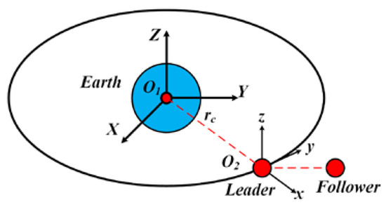
Figure 1.
The relative motion of a follower spacecraft with respect to a leader spacecraft.
It is assumed that both the leader and the follower spacecraft can be seen as particles. In Figure 1, represents the center of the Earth, and is the location of the leader spacecraft. is the Earth-centered-inertial coordinate frame, whereas is a moving coordinate system. The relative position of the follower spacecraft at the moment t in the coordinate system is . The relative motion can be described by the Hill–Clohessy–Wiltshire (HCW) equation [24]:
where denotes the control input of the follower spacecraft, and denotes the average orbital angular velocity of the leader spacecraft. is calculated as , where represents the relative displacement of target from the center of the Earth, and denotes the gravitational constant of the Earth.
We define the relative state between the follower spacecraft and the leader spacecraft by , where and denote the position vector and velocity vector, respectively. Therefore, the state–space equation associated with (1) can be expressed as follows:
where and are constant coefficient matrices, , , , , denotes the system state, and denotes the control input. ( is a known tight convex set, which bounds the control input.)
3. Problem Description
In the rendezvous phase, the follower spacecraft is required to achieve a specified relative position with respect to the leader spacecraft as soon as possible within a terminal specified time, while at the same time, the energy consumption during the control process needs to be minimized.
Suppose that at the initial time , the initial relative state between the follower spacecraft and the leader spacecraft is Then, the state–space equation (Equation (2)) can be written as follows:
Furthermore, the rendezvous-control problem at terminal time can be formulated as follows:
where is the target position, is the control force function, denotes the distance between the state of the follower spacecraft and the target state, and denotes the energy consumption. Obviously, the two objectives conflict with each other; thus, problem is a bi-objective probem.
The goal of the problem is trying to control the follower spacecraft to reach a target state while at the same time attempting to keep the energy consumption as low as possible.
From problem , we can see that the form of problem is similar to the optimization problem of the LQR method [25], which is as follows:
where , is target state, and and are two diagonal parameter matrices chosen by the decision maker.
However, general control methods (e.g., LQR, etc.) are mostly based on a single-objective optimization problem model and can only provide a single decision solution, while our method is designed for a multi-objective optimization problem, and we can provide multiple decision solutions for the user to choose from. In fact, the cost function of LQR can be considered as a weighted sum of , where and can be considered as the weights of two objectives; thus, the solution to LQR is encompassed by our solutions.
4. Methods
In order to numerically solve problem , we discretize the relative motion model system (4) into a discrete system and reformulate problem into a discretized multi–objective optimization model.
4.1. Discrete System
A continuous control system can be converted into a discrete one by numerical methods such as the zero-order hold method [26], Euler methods, and Runge–Kutta methods. In this paper, the zero-order hold method of [26] is used, where the signal values between two constitutive sampling are equal to the last sampling values. The zero-order hold method is widely used in autonomous vehicles [27], the course-keeping control for ships [28], and safety verification [29], among other things.
With the zero-order hold method, System (3) can be converted into the following:
where , , is the sampling period, and is the total number of discretization steps. Recursively, by substituting into system (6), we obtain the following:
Note that if ( is a constant), then the corresponding constraint can be written into the nonlinear form .
4.2. Multi-Objective Optimization Model of the Discretized Control Problem
The discretized version of problem is as follows:
where denotes the position of the relative motion between the follower spacecraft and the leader spacecraft at step ; denotes the velocity of the relative motion between the follower spacecraft and the leader spacecraft at step ; and is the total number of discretized steps. It is obvious that a set of control schemes can be obtained by solving the multi-objective optimization problem (). However, the following two difficulties often occur in solving a multi-objective optimization problem.
Firstly, solving a multi-objective optimization problem requires optimizing two or more objectives at the same time, and the objectives are often conflicting with each other. There is no single optimal solution that makes all objectives optimal at the same time. The solution of a multi-objective optimization problem is generally a set. This means that there may be an infinite number of solutions (control schemes), and only a finite number of solutions can be calculated. Therefore, a discrete representation of the whole solution set is often desirable.
Secondly, for a multi-objective optimization problem, each optimization objective has a different dimension; i.e., each objective has a different meaning in the actual problem, so it is meaningless to make a comparison without special treatment.
To solve the above problems, we introduce a multi-objective optimization method with a normalization strategy in the following subsections.
4.3. Multi-Objective Optimization Problem and ε-Constraint Method
Consider a multi-objective optimization problem (MOP) [30]:
is the non-empty feasible set in decision (or variable) space . is a vector-valued objective function, is composed of real-valued objective functions. , where for . The image of the feasible set under the objective function mapping is denoted as .
Definition 1 (ref. [30]).
For problem (MOP), a point is called a weakly (strictly) efficient solution in decision space if there is no such that for all . Correspondingly, point is called a weakly (strictly) nondominated point in objective space.
Definition 2 (ref. [30]).
For problem (MOP), a point is called an efficient solution in decision space if there is no such that both for all and for some j. Correspondingly, point is called a nondominated point in objective space.
We denote the sets of weakly (strictly) efficient solutions by () and the sets of efficient solutions by . The images of () under are denoted by (), and the images of under are called the nondominated set (Pareto front), which is denoted by
Here, we introduce the ε-constraint method (Figure 2). The ε-constraint method was proposed by Chankong and Haimes [31]. It is based on a scalarization where one of the objective functions is minimized, while all the other objective functions are bounded from above by means of additional constraints.
where and .
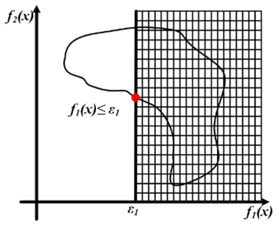
Figure 2.
Schematic diagram of ε-constraint method.
We denote the feasible set of the ε-constraint problem by the following:
It needs to be noted that can be always chosen to make feasible; i.e., . The following two main theorems [31] concerning the ε-constraint method specify the relationship between problem and (MOP):
Theorem 1.
For any , the following statements hold:
- If is an optimal solution of (), then ;
- If is a unique optimal solution of (), then .
Theorem 2.
A solution is efficient if and only if it is an optimal solution of for every , where for .
Therefore, for a multi-objective optimization problem, the Pareto front can be obtained by choosing a suitable set of and then solving a set of ε-constraint problems.
However, for a multi-objective orbital motion-control problem, constructing the complete Pareto front of its corresponding multi-objective optimization problem is difficult and less meaningful. Instead, a discrete representative set of the Pareto front is ideal to provide to the decision maker.
For the bi-objective optimization problem (), there are two dimensions in its objective space. For each dimension (objective), we have an individual minimal: they can be used to construct a set of equally spaced points. Furthermore, we can construct a set of ε-constraint problems accordingly. Then, solving this set of ε-constraint problems, a representative set of the Pareto front is obtained. The representative set has the property that the distance between two adjacent nondominated points in one dimension is equal.
4.4. Relative Orbital Motion Control Based on ε-Constraint
In this section, we propose a relative orbital motion-control algorithm based on the ε-constraint to solve problem . The ε-constraint method takes place in the normalized design metric space to avoid scaling deficiencies. Before introducing the algorithm, we first introduce the normalization method.
Let and , where . Their corresponding objective space points are denoted as and , respectively. We define the Utopia point as . Let be the distances between and the Utopia point , and let be the distances between and . That is,
With the above definitions, the normalized design metrics can be evaluated as follows:
By normalization, we eliminate the effect of different scales on different objectives. Based on this normalization method, when solving a multi-objective problem, we obtain a set of nondominated points such that each element value will fall into the interval [0,1]. The decision maker can compare different nondominated points more intuitively and thus choose a more appropriate control scheme according to different task situations.
Here, we show the relative orbital motion-control algorithm in Algorithm 1.
| Algorithm 1. Relative Orbital Motion-Control Algorithm Based on ε-Constraint |
| Input: , , , , , , , ; 1: Calculate , , and construct the discrete problem: where , and (); 2: Set sets , and to be empty; 3: Calculate and , then calculate and ; 4: Normalize the objective functions by the normalized design metrics (13); 5: Divide the interval [0,1] into subintervals of equal length, and add the right values of the subintervals to set ; 6: For each , , find an optimal solution of ; i.e., , set ; 7: For each , , find an optimal solution of ; i.e., . Set ; Output: The points in sets and and their corresponding optimal control solutions . |
It should be noted that when Algorithm 1 terminates, it can obtain a set of discrete non-dominated points in . These nondominated points correspond to a set of efficient control schemes ; thus, a set of representative efficient control schemes can be obtained.
5. Numerical Examples
In this section, we use an example to demonstrate the effectiveness of our proposed algorithm. Consider the relative control problem of a follower spacecraft. Suppose that the initial and the terminal state of the follower spacecraft is known. Our simulation example is from [32]. In the example, we assume that the initial moment , , where the initial position is , and the initial velocity is . Suppose that the target state of the spacecraft is , the control variable feasible domain is , the sampling period is , and the termination moment is .
We use the open-source package OPTI [33] to solve the optimization problem in the algorithm. We use Algorithm 1 to solve the multi-objective problem (). First, we solve and to obtain the payoff matrix for state control of the spacecraft in Table 1.

Table 1.
Payoff matrix for the state control.
Based on the above payoff matrix, the normalized design metrics can be evaluated as follows:
We divide into 20 equal parts; thus, elasticity parameter variable can be obtained. We run Algorithm 1 with the input of feasible set and to obtain a set of optimal solutions as well as the corresponding sets and , which are shown in Table 2.

Table 2.
The nondominated discrete point sets and obtained with Algorithm 1.
It is known that the objective functions are convex and continuously differentiable and that the control variable feasible set is convex. Thus, the optimal solutions obtained by solving are also efficient solutions of problem (MOP). Pareto front can be obtained by connecting the nondominated points in Table 2, as shown in Figure 3. In the figure, each nondominated point corresponds to a control scheme.
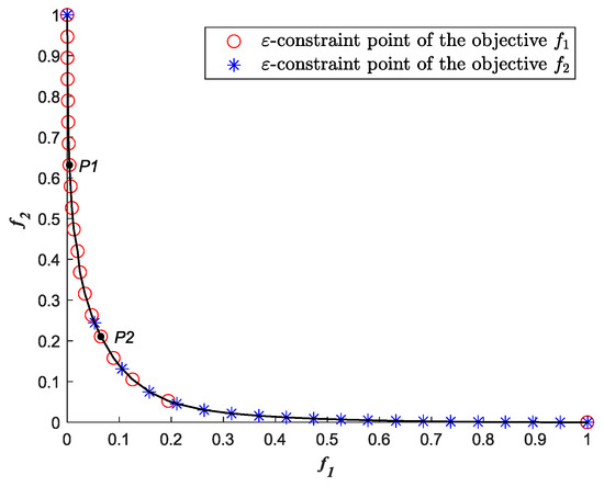
Figure 3.
Pareto front for orbital motion-control of spacecraft based on the ε-constraint method.
In Figure 3, the two ending points are corresponding to two individual minima. The nondominated points shown by asterisks “✳” are obtained by solving the ε-constraint problems with the orbital motion-control error as the objective function and the energy consumption bounded with an upper threshold as a constraint. The nondominated points shown by asterisks “○” are obtained by solving the ε-constraint problems with the energy consumption as the objective function and the orbital motion-control error bounded with an upper threshold as a constraint. Here, we select representative points and in Figure 3 for further analysis.
For the nondominated point in Figure 3, we show the corresponding simulation results in Figure 4. Figure 4 shows the position change curve, velocity change curve, and control force change curve of the relative motion of the spacecraft. From Figure 4, we can see that the spacecraft reaches termination state at about 7 s. At the same time, the control moment becomes zero, and the system reaches a steady state.
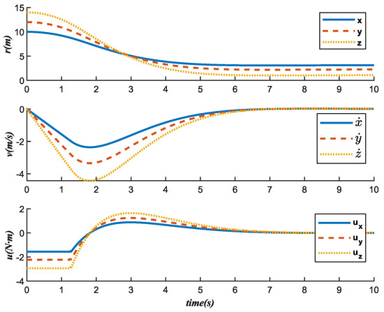
Figure 4.
State change trajectory of .
For the nondominated point in Figure 3, we show its corresponding simulation results in Figure 5. We can see that it takes nearly 10 s for the spacecraft to reach the target state while maintaining the steady state and with the control moment being zero. Comparing with , takes more time to achieve the target state than .
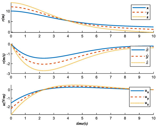
Figure 5.
State change trajectory of .
In addition, it is worth noting that from Figure 4 and Figure 5, we can see that the state change trajectory of and are smooth and without sudden changes. This indicates that the control scheme we obtained is reasonable, and such a control scheme can also make the control system more stable.
We also show the energy consumptions (the second objective value of ()) corresponding to and in Figure 6.
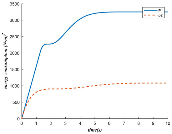
Figure 6.
The energy consumption of and .
It can be seen from Figure 4, Figure 5 and Figure 6 that the control scheme corresponding to reaches the target state faster than but consumes more energy. Because and are two conflicting objectives, for a nondominated point, improving one objective makes another objective worse.
From the above, it can be seen that the control force sequence can be obtained by solving the multi-objective optimization problem. This method optimizes the orbital motion error and the energy consumption at the same time. The numerical results show the effectiveness of the method.
In summary, for the orbital motion-control problem () where the objective functions are convex continuously differentiable, and the feasible set of control variables is convex, the complete Pareto front can be obtained by using relative orbital motion-control algorithm based on ε-constraint. The decision maker can choose a more appropriate control scheme according to the specific situation.
6. Conclusions
In this paper, we investigate a problem of relative orbital motion-control that requires not only the follower spacecraft to achieve its target state as soon as possible but also low energy consumption. A multi-objective optimization model for the relative orbital motion-control of spacecraft is presented. Then, a multi-objective relative orbital motion-control algorithm based on ε-constraint is proposed. Discrete nondominated points of the multi-objective problem are obtained. The control schemes, which correspond to the discrete nondominated points, are given. Thus, the decision maker can choose the most suitable control scheme. Finally, the numerical results show the effectiveness of the proposed algorithm. The control scheme we obtained is for the discrete system, and there are still errors for the continuous system. Although the discrete system is theoretically very close to the continuous system as long as the discrete step size is small enough, the smaller the step size, the larger the number of discrete steps. When the number of discrete steps increases, the computational difficulty increases as well. In addition, only the two objectives of orbital motion-control and energy consumption are considered in this paper. For orbital motion-control problems with three or more objectives, it remains to be solved how to give a representative set of the Pareto front quickly. These are the future works of our research.
Author Contributions
Conceptualization, L.S.; methodology, L.S.; software, J.G. and H.M.; validation, all authors; investigation, J.G. and H.M.; writing—original draft preparation, J.G. and L.S. All authors have read and agreed to the published version of the manuscript.
Funding
This work was partially supported by the National Natural Science Foundation of China (No. 12071025), the Natural Science Foundation of Guangdong Province, China (No. 2022A1515011172).
Institutional Review Board Statement
Not applicable.
Informed Consent Statement
Not applicable.
Data Availability Statement
All data generated or analyzed during this study are included in this published article.
Conflicts of Interest
The authors declare no conflict of interest.
References
- Luo, C.; Sun, J.; Wen, H.; Jin, D. Dynamics of a tethered satellite formation for space exploration modeled via ANCF. Acta Astronaut. 2020, 177, 882–890. [Google Scholar] [CrossRef]
- You, Z. Space Microsystems and Micro/Nano Satellites; Butterworth-Heinemann: Oxford, UK, 2017. [Google Scholar]
- Weihua, Z.; Go, T.H. Robust cooperative leader-follower formation flight control. In Proceedings of the 2010 11th International Conference on Control Automation Robotics & Vision, Singapore, 7–10 December 2010; pp. 275–280. [Google Scholar]
- Shahbazi, B.; Malekzadeh, M.; Koofigar, H.R. Robust constrained attitude control of spacecraft formation flying in the presence of disturbances. IEEE Trans. Aerosp. Electron. Syst. 2017, 53, 2534–2543. [Google Scholar] [CrossRef]
- Liang, H.; Wang, J.; Sun, Z. Robust decentralized coordinated attitude control of spacecraft formation. Acta Astronaut. 2011, 69, 280–288. [Google Scholar] [CrossRef]
- Wang, P.; Hadaegh, F.Y. Coordination and control of multiple microspacecraft moving in formation. J. Astronaut. Sci. 1996, 44, 315–355. [Google Scholar]
- Wang, P.K.-C.; Hadaegh, F.; Lau, K. Synchronized formation rotation and attitude control of multiple free-flying spacecraft. J. Guid. Control Dyn. 1999, 22, 28–35. [Google Scholar] [CrossRef]
- Kristiansen, R.; Nicklasson, P.J. Spacecraft formation flying: A review and new results on state feedback control. Acta Astronaut. 2009, 65, 1537–1552. [Google Scholar] [CrossRef]
- Wang, J.; Sun, Z. 6-DOF robust adaptive terminal sliding mode control for spacecraft formation flying. Acta Astronaut. 2012, 73, 76–87. [Google Scholar] [CrossRef]
- Liu, H.; Tian, Y.; Lewis, F.L.; Wan, Y.; Valavanis, K.P. Robust formation flying control for a team of satellites subject to nonlinearities and uncertainties. Aerosp. Sci. Technol. 2019, 95, 105455. [Google Scholar] [CrossRef]
- Giri, D.K. Fast finite-time sliding mode magnetic attitude control of satellites. In Proceedings of the AIAA Scitech 2019 Forum, San Diego, CA, USA, 7–11 January 2019; p. 933. [Google Scholar]
- Bayat, F.; Javaheri, M. Two-layer terminal sliding mode attitude control of satellites equipped with reaction wheels. Asian J. Control 2020, 22, 388–397. [Google Scholar] [CrossRef]
- Najafizadeh Sari, N.; Jahanshahi, H.; Fakoor, M. Adaptive fuzzy PID control strategy for spacecraft attitude control. Int. J. Fuzzy Syst. 2019, 21, 769–781. [Google Scholar] [CrossRef]
- Golzari, A.; Pishkenari, H.N.; Salarieh, H.; Abdollahi, T. Quaternion based linear time-varying model predictive attitude control for satellites with two reaction wheels. Aerosp. Sci. Technol. 2020, 98, 105677. [Google Scholar] [CrossRef]
- Li, H.; Zhang, Y.; Qiang, W.; Li, B. Relative attitude control in satellite formation flying with information delay. In Proceedings of the 2006 6th World Congress on Intelligent Control and Automation, Dalian, China, 21–23 June 2006; pp. 8453–8456. [Google Scholar]
- Erkec, T.Y.; Hajiyev, C. Fault-tolerant state estimation methods of cluster satellites. Adv. Space Res. 2022, in press. [Google Scholar]
- Erkeç, T.Y.; Hajiyev, C. Formation Flight for Close Satellites With GPS-Based State Estimation Method. IEEE Sens. J. 2022, 22, 15457–15464. [Google Scholar] [CrossRef]
- Lee, T. Relative attitude control of two spacecraft on SO (3) using line-of-sight observations. In Proceedings of the 2012 American Control Conference (ACC), Montreal, Canada, 27–29 June 2012; pp. 167–172. [Google Scholar]
- Li, P.; Yue, X.; Chi, X.; Du, C. Optimal relative attitude tracking control for spacecraft proximity operation. In Proceedings of the 2013 25th Chinese Control and Decision Conference (CCDC), Guiyang, China, 25–27 May 2013; pp. 4582–4587. [Google Scholar]
- Sun, L.; Huo, W.; Jiao, Z. Robust adaptive relative position and attitude control for spacecraft autonomous proximity. ISA Trans. 2016, 63, 11–19. [Google Scholar] [CrossRef] [PubMed]
- Huang, Y.; Jia, Y. Adaptive fixed-time relative position tracking and attitude synchronization control for non-cooperative target spacecraft fly-around mission. J. Frankl. Inst. 2017, 354, 8461–8489. [Google Scholar] [CrossRef]
- Wang, Y.; Ji, H. Integrated relative position and attitude control for spacecraft rendezvous with ISS and finite-time convergence. Aerosp. Sci. Technol. 2019, 85, 234–245. [Google Scholar] [CrossRef]
- Misra, G.; Bai, X. Robust disturbance observer-based control for relative attitude tracking using sum-of-squares programming. J. Guid. Control. Dyn. 2020, 43, 806–813. [Google Scholar] [CrossRef]
- Hill, G.W. Researches in the lunar theory. Am. J. Math. 1878, 1, 5–26. [Google Scholar] [CrossRef]
- Guarnaccia, L.; Bevilacqua, R.; Pastorelli, S.P. Suboptimal LQR-based spacecraft full motion control: Theory and experimentation. Acta Astronaut. 2016, 122, 114–136. [Google Scholar] [CrossRef]
- Franklin, G.F.; Powell, J.D.; Workman, M.L. Digital Control of Dynamic Systems; Addison-Wesley: Reading, MA, USA, 1998; Volume 3. [Google Scholar]
- Brown, M.; Funke, J.; Erlien, S.; Gerdes, J.C. Safe driving envelopes for path tracking in autonomous vehicles. Control Eng. Pract. 2017, 61, 307–316. [Google Scholar] [CrossRef]
- Yan, Z.; Zhang, X.; Zhu, H.; Li, Z. Course-keeping control for ships with nonlinear feedback and zero-order holder component. Ocean Eng. 2020, 209, 107461. [Google Scholar] [CrossRef]
- Ghaffari, A.; Abel, I.; Ricketts, D.; Lerner, S.; Krstić, M. Safety verification using barrier certificates with application to double integrator with input saturation and zero-order hold. In Proceedings of the 2018 Annual American Control Conference (ACC), Milwaukee, WI, USA, 27–29 June 2018; pp. 4664–4669. [Google Scholar]
- Ehrgott, M. Multicriteria Optimization; Springer Science & Business Media: Berlin/Heidelberg, Germany, 2005; Volume 491. [Google Scholar]
- Chankong, V.; Haimes, Y.Y. Multiobjective Decision Making: Theory and Methodology; Courier Dover Publications: Mineola, NY, USA, 2008. [Google Scholar]
- Lizhen, S.; Haibin, M.; Renhong, H.; Hongjin, L. Reachable set estimation for spacecraft relative motion based on bang-bang principle. Chin. J. Aeronaut. 2022, 36, 229–240. [Google Scholar]
- OPTI Toolbox. Available online: https://gitcode.net/mirrors/jonathancurrie/OPTI?utm_source=csdn_github_accelerator (accessed on 10 October 2022).
Disclaimer/Publisher’s Note: The statements, opinions and data contained in all publications are solely those of the individual author(s) and contributor(s) and not of MDPI and/or the editor(s). MDPI and/or the editor(s) disclaim responsibility for any injury to people or property resulting from any ideas, methods, instructions or products referred to in the content. |
© 2023 by the authors. Licensee MDPI, Basel, Switzerland. This article is an open access article distributed under the terms and conditions of the Creative Commons Attribution (CC BY) license (https://creativecommons.org/licenses/by/4.0/).