1. Introduction
Bringing back samples from the Martian soil has long been a goal for space agencies and a critical milestone in the process of understanding the history of the planet. The study of such samples would address in detail the questions related to the potential origin and evolution of life on Mars and assess its habitability.
A NASA-ESA MSR campaign, comprising three missions, aims to retrieve Martian soil samples using robotic systems. Initiated in 2020 with NASA’s Perseverance rover [
1], the campaign involves collecting and depositing sample tubes on Mars. The next phase involves the collection of these samples, transferring them to the MAV for return to Earth via a dedicated orbiter. NASA’s current MAV concept, designed by Lockheed Martin [
2], is a two-stage solid-propelled rocket. It has the critical task of being the first rocket launched from another planet. It must endure the harsh Martian environment, withstand rough landing, maintain simplicity to avoid failures, and be compact enough to fit into the Sample Retrieval Lander (SRL). Once launched from Mars, the MAV will rendezvous with the Sample Return Orbiter (SRO) to return the samples to Earth. The joint SRL and MAV launch is scheduled for 2028 from Kennedy Space Centre [
3].
This preliminary design study was conducted in collaboration with the technical support of a German space launch company called HyImpulse. Leveraging insights from prior examinations of the Hyplox10 engine, the concept of proposing a European alternative to NASA’s MAV emerged [
4]. The primary objective of this project is to develop a MAV using the Hyplox10 hybrid propulsion system provided by HyImpulse. This specific study will predominantly focus on the mechanical aspects of a two-stage Hybrid MAV, encompassing component sizing, part design, and rigorous mechanical integrity verification using FEA.
1.1. Challenges and Design Drivers
Designing a MAV for the MSR campaign remains a significant challenge due to its critical role in the mission. Launching a rocket from another planet is high-risk, earning this segment the label of the highest system technology risk [
5].
Key challenges include the MAV’s ability to endure 15 G loads during the SRL’s EDL [
6] and avoid a resonance of the structure below 24 Hz. It must be both structurally robust and compact enough to fit the lander’s space constraints. Therefore, the MAV ought to keep its dimensions under 0.57 m in diameter and 3 m in height, and keep its GLOM below 400 kg [
7].
The interplanetary journey and landing on Mars represent just one aspect of the challenge. Before entering the commissioning phase, which involves testing the rocket components and launching the rocket from the Red Planet, the MAV must endure Mars’ challenging environment for months [
7].
During Martian winters, potential temperatures as low as −130
C challenge propellant storability. Even within the chosen launching site [
7] of the Jezero crater where temperatures are warmer, the MAV must withstand drastic temperature drops and launch at an operational temperature of −20
C.
The key requirements associated with the design of the MAV are listed in
Table 1. These requirements have been identified during the literature survey and most of them are directly formulated by NASA in the scope of the MSR Campaign [
7].
1.2. MAV Concepts and Research State of the Art
In the early 2000s, during the preliminary design phase of the MAV, a NASA team was assigned the task of formulating a MAV concept that aimed to achieve minimum mass yet maintain robust margins for ensuring a high likelihood of success [
8]. The team evaluated MAV concepts proposed by three American industrial contractors: a two-stage solid propulsion MAV from Lockheed Martin, a two-stage liquid MAV from Boeing, and a two-stage gel MAV by TRW [
8]. It was already determined by NASA that liquid propulsion was unfeasible within the space constraints imposed by the mission. The liquid system incurred a bulk density penalty, and the Specific Impulse (Isp) of pressure-fed engines resulted in a MAV solution that was larger in size and greater in mass compared to either the solid or gel solutions [
8]. Both the solid and gel solutions appeared more suitable for the mission, with a slight preference for the solid configuration, benefiting from a better flight heritage than the gel solution. At that time, Lockheed Martin even considered propelling its second stage with hybrid propulsion [
8].
Subsequent to this study, NASA requested Lockheed Martin to proceed with its solid concept [
9] while JPL teams initiated studies on a Hybrid MAV concept [
10] which uses a solid fuel core and liquid oxidizer [
11]. Concurrently with NASA’s studies, various MAV concepts were developed in the literature, proposing liquid bi-propellant MAVs [
12], liquid mono-propellant systems [
13], and two-stage hybrids [
14]. Despite their differences, all these concepts share similar dimensions and overall configurations, primarily distinguishing themselves by the type of propulsion used, which becomes the focal point of NASA’s decision-making process. In the context of the MSR campaign, solid, liquid, and hybrid propulsion systems present several advantages and drawbacks:
- 1.
Solid propulsion: high thrust and high heritage technology that ensures a reliable way to launch the samples into orbit. The low thermal resilience of the propellant necessitates meticulous thermal management, especially considering the cold environment of Mars. This is essential to prevent issues such as grain cracking or wall separation in the combustion chamber. Additionally, the non-restartability inherent in this kind of system impacts the precision of the delivered orbit and reduces mission flexibility.
- 2.
Liquid propulsion: mono and bipropellant engines were considered for a MAV application. Despite its relatively low thrust, this type of propulsion provides the highest Isp and is able to achieve a low GLOM, especially in the two-stage configuration. Two versions were envisioned, one pressure regulated and a pump-fed option. These technologies have a strong space heritage and exhibit competitive performance. However, their feeding systems are either high-cost or at a low Technology Readiness Level (TRL). Additionally, they contribute excessive mass to the system, and as mentioned earlier, the dimensions of the feeding system might pose a particular challenge in complying with the space constraints imposed by the lander.
- 3.
Hybrid propulsion: considered safer and cheaper to develop, the hybrid engines are also excellent candidates for a MAV application. These engines provide a higher thrust than the bipropellant motors and deliver a high Isp. The diverse mass estimations of [
6,
7,
8,
14] show that Hybrid MAVs are the lightest of the three configurations and have proven to be the most suited for the cold temperatures of Mars. The primary drawback inherent in this type of propulsion is its lack of maturity and added complexity compared to the other two propulsion systems, which benefit from extensive flight heritage.
In the end, NASA opted to further develop and enhance the maturity of two concepts: the hybrid and solid MAVs [
6], conducting a comparative study to select between these two options. This study examined the design of critical subsystems such as Reaction Control Systems (RCS), separation, and structures for each concept, considering their TRL, contribution to the vehicle design, and associated risks. The study revealed that the hybrid concept exhibited better potential in terms of reducing GLOM and thermal resilience, whereas the solid concept stood out due to its high TRL and flight heritage, thus minimizing overall mission risks.
The final decision was to select the two-stage solid concept developed by Lockheed Martin, primarily due to the hybrid concept’s lack of maturity, which posed a threat to meeting the mission timeline and increased mission risks.
Since then, the maturity of the two-stage solid concept has continued to progress [
3,
15], with more precise definition of attachment points to the lander, structural definition and analyses, Computational Fluid Dynamics (CFD) analyses, thermal control system, Thrust Vector Control (TVC), Guidance Navigation and Control (GNC), avionics, and other subsystem designs. The rocket has been able to meet most mission constraints; however, as initially anticipated, there are still significant concerns about the final system’s mass, considering the numerous subsystems that need to be designed [
3,
15]. These references truly serve as benchmarks for this paper, representing the baseline level of maturity a concept should attain to be competitive with NASA’s concept.
Based on this overview of the state-of-the-art existing MAV concepts, the idea emerged to explore the concept of a Hybrid MAV utilizing promising paraffin-based rocket technology. For this new concept to surpass NASA’s approach, it would need to deliver performance at least on par with NASA’s solid concept while significantly reducing the GLOM, which is what would offer a two-stage Hybrid MAV [
14]. A study [
14] showed how staging would benefit for a great reduction of the GLOM and greatly inspired the MAV configuration of this paper. Considering the potentially postponed timeline envisioned for the MSR mission, there exists an opportunity for a hybrid concept to mature and potentially outperform the currently chosen concept.
1.3. Hybrid Propulsion
A hybrid rocket consists of a solid fuel and liquid oxidizer (or sometimes the opposite). To produce the thrust, the liquid oxidizer is vaporized and injected into the solid fuel where an igniter lights the combustion [
5]. The oxidizer and fuel are separated making the whole system inert when they are not mixed, thus enhancing the safety. The hybrid propellants are non-toxic and can be stored during long periods without any loss in performance [
5].
Most hybrid motors suffer from a low burning rate making the use of multi-port grain [
5] or complex grain designs almost mandatory. These grain structures lead to the necessity to incorporate complex web supports to sustain the fuel, especially at the end of the burn when the integrity of the grain is low. It leads eventually to an uneven burning and propellant leftovers. To avoid this, modern hybrid rockets are using paraffin-based fuels which can deliver much higher regression rates [
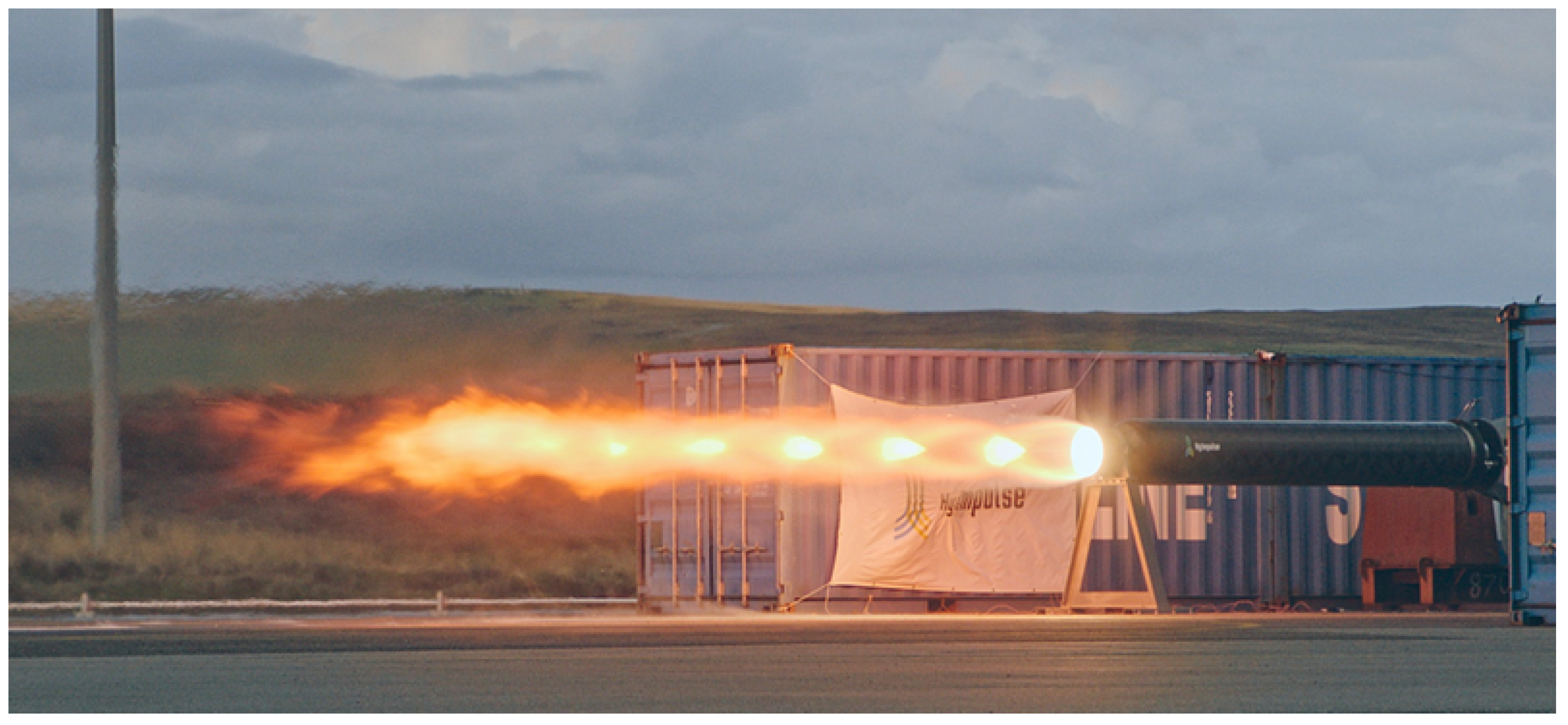
5]. Companies like HyImpulse are using these paraffin-based fuels to develop more compact engine designs with high-thrust density [
16] like their Hyplox75 engine, displayed in
Figure 1, which can deliver a thrust of 75 kN.
For the oxidizer, Mixed Oxides of Nitrogen (MON) oxidizers appear to be the most common and relevant choice for a MAV according to the literature [
7,
10,
17]. Indeed, NASA envisioned MON25 for its hybrid concept [
10] because of its thermal resilience. These mixtures can withstand low temperature (−55
C and −80
C freezing points for, respectively, MON25 and MON30 [
17]) which enables the propellant to handle the nominal temperature of −40
C that is foreseen at Jezero Crater.
Unlike the solid configuration, the hybrid configuration does not require the use of a heavy thermal igloo inside the lander to keep the propellant warm. It enables us to considerably reduce the GLOM by at least 30 kg [
7] and reduce the power needs of the rocket and lander. Moreover, the restart ability of the engine enables us to further reduce the GLOM by performing maneuvers such as gravity turns, unlike solid rockets which cannot stop their burn once they are ignited. If we only look at the performance, hybrid appears as the best solution, by being better in almost every aspect from the mass delivered to the final speed it could reach. But unfortunately, this technology lacked maturity to be considered for the MSR campaign. The launch window envisioned by NASA at the time of the trade-off was as early as 2026 [
18]. As stated in [
18], NASA strongly recommended a TRL of six for the mission preliminary design, and the studies from the hybrid propulsion team estimated their design to TRL 5+ (depending on the parts considered). Despite the promising performances and resilience that a Hybrid MAV would offer, the solid configuration was chosen as it was the most mature technology. The amount of challenges to overcome for the hybrid concept to reach maturity was judged too high. Nevertheless, the growth of companies like HyImpulse reassesses the possibility of hybrid engines to propel a future MAV. If their technology reaches high TRL levels and if it proves to be successful, it could open the way for a multitude of rocket applications. The observations made in [
18] will serve as a guide for tackling difficult aspects of the mission.
2. Sizing
2.1. MAV’s Hybrid Engine
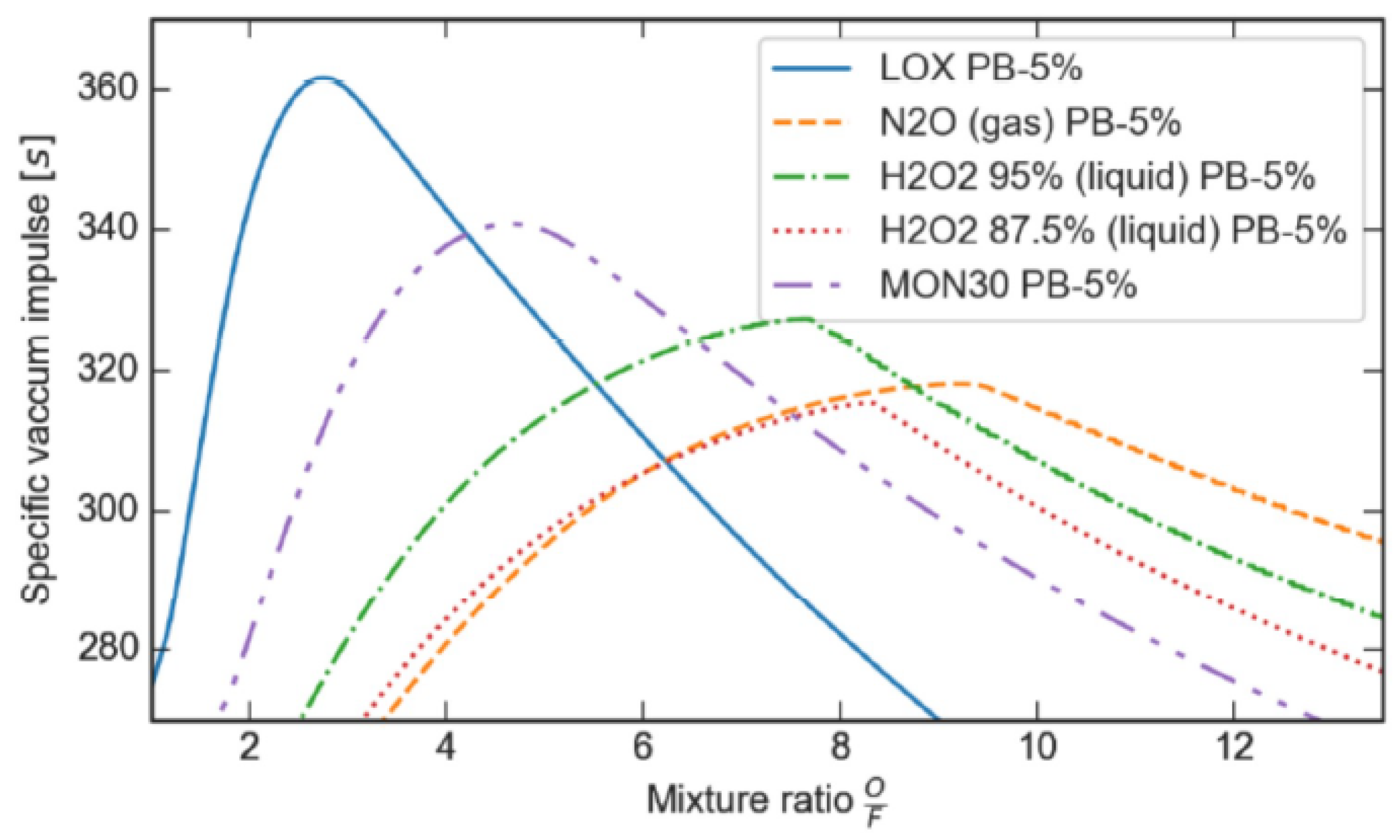
The MAV propulsion will use technologies developed by HyImpulse GmbH. HyImpulse has built and tested successfully a 10 kN thruster, the HyPLOX10, manufactured by German company HyImpulse Technologies GmbH in Lampoldshausen, which uses liquid oxygen as the oxidizer. With a paraffin-based fuel, the specific vacuum impulse can reach about 362 s with a mixture ratio close to 2.75, as shown by
Figure 2.
However, liquid oxygen is a poor storable propellant because it is known to vaporize when stored at temperatures above its boiling point. As shown by
Figure 2, MON30 is the second possibility, with a specific impulse of approximately 340 s for a mixture ratio close to 4.5. MONs are a mixture of nitrogen tetroxide (N
2O
4) and nitric oxide (NO). Nitric oxide is known to have a low boiling point, which implies decreasing the freezing point of the mixture with N
2O
4. According to the literature [
16], adding nitric oxide to nitrogen tetroxide also decreases the corrosivity of the mixture, which is in favour of long-term storability. Thus, the proposed propulsion system for the Hybrid MAV consists of a paraffin-based fuel and MON30 as the oxidizer. This hybrid engine, based on the HyPLOX10 motor developed by HyImpulse [
4], has the properties gathered in
Table 2 below. Concerning the ISP, an efficiency of 92% has been taken. The value of 340s is ideal and may not reflect the reality, given that 100% efficiency is most of the time impossible to achieve.
2.2. Staging
Mars’ launch conditions provide benefits compared to Earth. The lower gravity and thinner atmosphere lead to a significantly reduced estimation of the
budget, with only 4765 m/s, which is half of what Earth-based rockets require. On Earth, SSTO launch vehicles are impractical due to limited payload fractions. Staging addresses this challenge by discarding used sections, enhancing efficiency for subsequent stages. However, for Martian launches, staging might not be mandatory, making it an optional consideration. NASA’s Hybrid MAV concept [
10], for example, was a SSTO. The aim of the following section is to do a first sizing of the rocket and assess whether a single or two-stage MAV is most suited for this mission.
Table 3 below gathers the input numbers for the sizing taken from the mission requirements, the preliminary mass budget, and HyImpulse’s engine performance estimations.
Here, the inert mass does not include the propulsion system mass (Nozzle, pipes, and combustion chamber) as these were approached with a modular mindset, where the inert mass stayed the same for each rocket, regardless of the number of stages. For each stage, a propulsion system mass of 9 kg (margins included) was added to the inert mass to create the overall structural mass. Each stage separation occurs with the shedding of one propulsion system mass and a fraction of the inert mass based on the staging fractions.
An iterative design process was used to reduce the
to meet the required maximum value and minimize the GLOM, which is a key requirement for the MAV. Various stage configurations involving 1, 2, 3, or 4 stages, each with different stage fractions, were initially considered. However, it revealed that the advantages of additional staging diminish rapidly as complexity increases. Therefore, this study focused on single and two-stage configurations. The “Initial” configurations both start with a 400 kg GLOM and an unoptimized propellant mass, while the “Final” configurations have a reduced GLOM achieved through lower propellant mass. The results of all four configurations are gathered in
Table 4:
The efficiency of the TSTO configuration enables us to drastically reduce the GLOM to less than 300 kg, which is the initial goal that was set by NASA at the beginning of the project [
18]. As indicated in
Table 4, both concepts can attain the desired orbit with initial
values exceeding the required 4765 m/s. The SSTO configuration offers only a narrow margin above the minimum
at 4909 m/s, while the TSTO significantly outperforms with 6000 m/s, providing an additional margin of 26%. To minimize the GLOM, the propellant mass is adjusted until it aligns with the required
. The TSTO configurations, initially exhibiting superior performance, outperform the SSTO in terms of GLOM, requiring only 292.8 kg compared to 381.7 kg.
A trade-off was conducted to determine whether the SSTO or TSTO configuration should be adopted. This evaluation, based on the results presented in
Table 4, emphasizes the significance of GLOM and the final speed achievable by each configuration, alongside other factors such as complexity, reliability, and cost.
After weighing each factor, the authors judged the advantageous GLOM savings to outweigh the additional complexity associated with a two-stage configuration. The decision prioritized performance over complexity. A special focus will be made on interstage and stage jettisoning technologies, which are the primary components contributing to the configuration’s complexity.
3. Mechanical Design
3.1. General Configuration
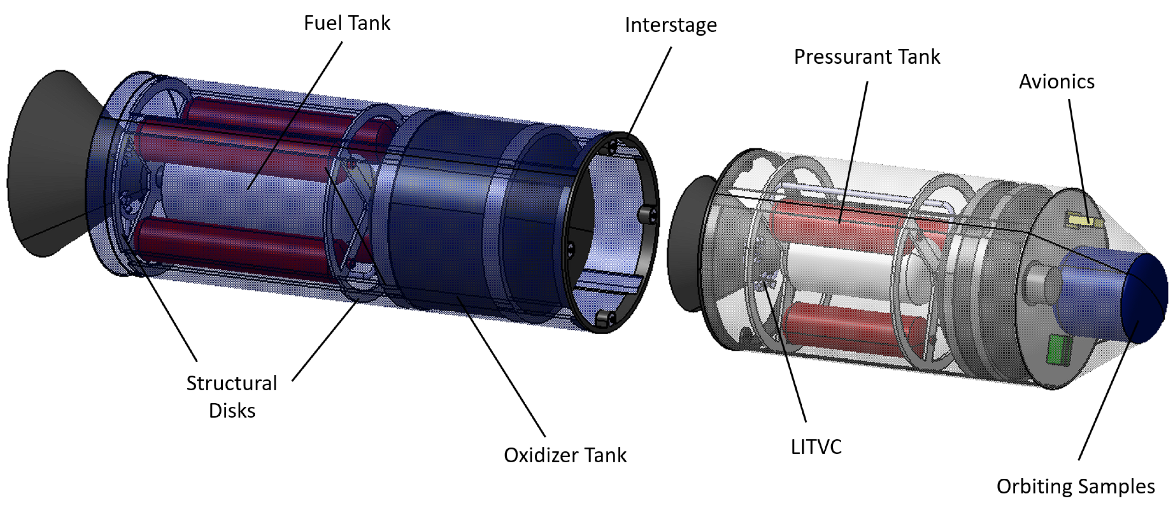
The configuration proposed in this study is influenced by concepts explored in the literature survey and adheres to the conventional design of a hybrid rocket. As displayed in
Figure 3, the rocket’s upper section features a nose cone containing the samples and avionics. Just below, a slim platform separates the payload from the oxidizer tank. This tank connects to the rocket tube through two disks. Below the oxidizer, the second stage combustion chamber is flanked by three pressurizing tanks. These tanks are held together axially by two reinforcement disks affixed to the rocket body. The upper section of the rocket is completed by the second stage nozzle, accompanied by the Liquid Injection Thrust Vector Control (LITVC) system.
The first stage of the rocket has a similar configuration, with the only distinction being the number of pressurizing tanks, which is four instead of three. Both stages are linked through a clamp band system engineered to be released by a Hold Down and Release Mechanism (HDRM) during the ascent phase. The overall dimensions of the rocket are presented in
Figure 4.
The configuration showcased in
Figure 3 distinguishes itself notably through its staging. The Two-Stage configuration with Hybrid Propulsion is a novel approach, which combines the resilience allowed by hybrid propulsion coupled with the power provided by staging. The integration of radial disks within the structure serves as an efficient method to absorb atypical transversal loads experienced by the rocket without significantly increasing inert mass. Additionally, the compact layout of the components allows for a rocket which complies with the space constraint requirement.
3.2. Material
Optimizing the MAV’s GLOM is a core objective, making material selection crucial. Striking a balance among mass, strength, and stiffness is essential for the structure, including the rocket tube, disks, and tanks.
The choice was made to create a hybrid structure, combining aluminum alloy and Carbon Fiber Reinforced Polymer (CFRP). This pairing offers optimal stiffness and strength with a relatively light mass, aligning well with the MAV’s needs.
For primary mass-contributing components like rocket tubes and tanks, carbon fiber is employed. Aluminum alloy is reserved for smaller components needing added stiffness or those challenging to make with composites, like valves, nozzles, or certain rings. Characteristics of these materials are summarized in
Table 5 and
Table 6.
It is important to note that the values used in
Table 5 and
Table 6 will serve as an input for the structural analysis performed later. For a first analysis, the mechanical values taken here are assumed to be valid at an ambient temperature of +20
C. In the scope of the first analysis, which aims to define the first dimensions of the structure, this assumption is judged acceptable by the authors. Further analysis will need to include this temperature influence to fully answer REQ-MEC-03.
3.3. Internal Structure
The main challenge faced during landing on Mars is not solely about the magnitude of the load, which can reach up to 15 G, but the unique direction of the load transverse to the rocket instead of the typical axial direction encountered during vertical launches.
In order to effectively manage this challenge and bolster the transverse rigidity of the rocket, a pair of disks is incorporated into each stage. These disks are designed to absorb the transverse landing loads without significantly increasing the inert mass of the rocket.
To determine a suitable thickness for both the rocket tube and disks, two aspects are considered: static requirements and dynamic requirements. Since dynamic loads are more challenging for the structure, a pivotal initial step involves designing the tube to effectively withstand the vibrations during launch.
To establish an appropriate thickness for the rocket tube, a practical approach entails calculating the fundamental frequency of the rocket using a formula derived from [
21]. This formula is particularly relevant as most spacecraft, including rockets, demonstrate a fundamental mode shape resembling a beam bending mode when constrained at the launch vehicle interface. By assuming a cantilever beam and a minimum primary frequency, the tube’s thickness can be determined through the following equation:
With E Young’s modulus of rocket tube’s material, M the mass of the spacecraft, L the length from beam root to center of mass, and I the area moment of inertia [
21] defined as:
If we substitute (2) in (1), we can isolate the thickness of the rocket tube. By taking the mechanical values of CFRP, the dimensions of the tube and a fundamental frequency of 24 Hz, the equation outputs a minimum thickness of:
It means that the design optimization will not go below the thickness of 1 mm. This estimation serves as a valuable starting point for the design process, allowing for an initial assessment of the tube’s thickness and material selection.
3.4. Tanks and Combustion Chambers
The dimensions of the oxidizer and fuel tanks are determined based on key parameters such as propellant mass, mixture ratio, and density. In pursuit of an optimum balance between structural robustness and efficient use of space, the tanks are designed with a cylindrical shape and elliptical ends.
The tank design underwent numerous iterations to achieve an optimal configuration that maximizes the internal space of the rocket while meeting dimensional requirements. To ensure integration, the tanks were fixed at a maximum diameter of 0.27 m, allowing for a reasonable margin for insertion into the rocket tube. Additionally, the tanks’ height was minimized to keep the overall rocket height below 3 m.
Maintaining this height requirement (REQ-MEC-01) posed a significant challenge, especially when sizing the combustion chamber. Designing the combustion chamber of a hybrid engine requires careful consideration of the Length to Diameter (L/D) ratio, directly impacting engine performance. A low L/D ratio can lead to unstable combustion, reduced regression rate, suboptimal fuel/oxidizer mixing, pressure losses, and unfavorable flow dynamics [
22].
Quantitatively estimating the impact of a specific L/D ratio on engine performance requires dedicated fluid mechanics analysis. To meet the space requirement (REQ-MEC-01), the design choice was made by the authors to maximize the combustion chamber’s height, resulting in an achieved L/D ratio of 2.5. Although this ratio is relatively low according to the literature [
22], it was deemed sufficient for this project’s scope, despite potential implications on engine performance. By reducing the gaps between rocket components, the rocket’s size was kept just under 3 m.
From a structural perspective, the only parameter that requires optimization is the thickness of the tanks. These tanks must withstand the elevated pressure necessary to maintain the propellant in its liquid state, all while enduring substantial internal stresses. To achieve this, we use Barlow’s formula to design the tanks:
If we consider CFRP tanks pressurized at 200 bar, it means that we need a tank thickness of a minimum:
4. Structural Analysis
Abaqus software is employed for a comprehensive evaluation of the structure, involving two key assessments to comprehend its strength and stiffness:
Static Analysis: This examines the MAV’s response to demanding G-Loads during landing. Applying static loads helps assess the structure’s integrity.
Dynamic Analysis: Here, the fundamental frequencies are scrutinized to prevent resonance, a potential threat to structural stability. Ensuring safe fundamental frequencies is vital for overall performance and safety.
To effectively run the analysis and save computing time, the focus is on the primary MAV structure which includes rocket tubes from each of the stages and the four reinforcement disks. Other components like nozzles, tanks, avionics, and payload are excluded from these analyses.
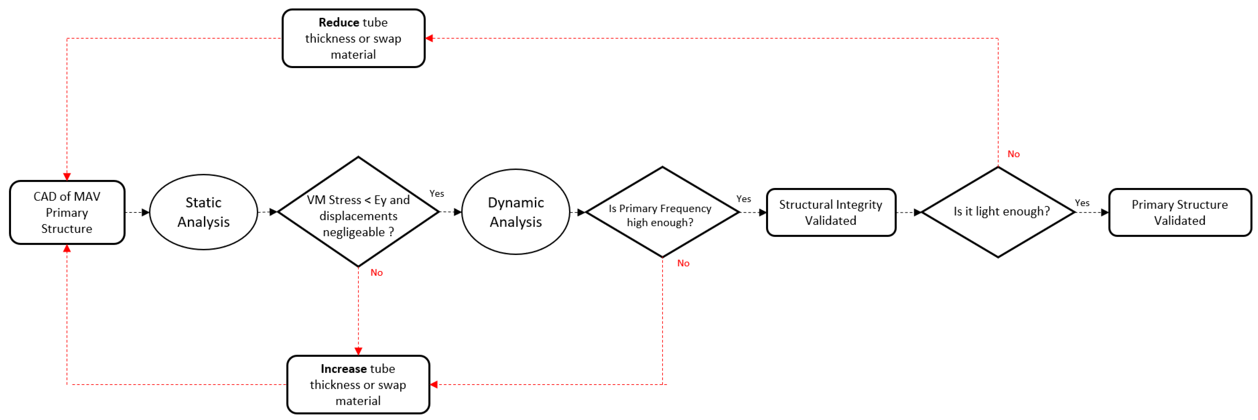
This section aims to validate the primary structure’s integrity while minimizing GLOM by proposing the lightest possible mass. As depicted in the diagram in
Figure 5, the goal is to achieve a lightweight yet stiff structure, resilient to EDL loads and low resonance during critical mission phases. Iterative designs will explore material adjustments (Aluminum alloy or CFRP) and thickness modifications for tubes and disks.
Each part was directly imported into the Abaqus software, where two materials were defined: aluminum alloy 7075-T6 and CFRP. The mechanical properties of aluminum, including Young’s modulus and Poisson’s coefficient, were used for its definition. For CFRP, engineering constants were computed within the software to generate the material’s stiffness matrix, enabling stress and displacement calculations. The density of both materials was also specified. The values used for the simulation are taken from
Table 5 and
Table 6 in the “Material” subsection. For the CFRP material, only one orientation of the fibers has been tested; the fibers were oriented to provide the best rigidity to the static landing load of 15 G.
Solid and homogeneous sections were defined for each material, and the parts were assembled using the assembly section to create the two-stage MAV. The disks were positioned in the same arrangement as in the complete assembly.
For each analysis, a specific step was created to define the type of study to be conducted. In the case of the static analysis, a “Quasi-Static Step, General” was defined. An important step in the simulation setup is the parts interaction. It was established by defining contact interactions for surfaces with potential contact. Parts were virtually connected with nuts and attachments to restrict relative movement.
Load and boundary conditions were defined. In the static analysis example, a gravity load representing 15G was applied in the +Z direction. In this case, a gravity load magnitude of
was applied, with
as the GLOM of the MAV and g as the gravitational acceleration. Boundary conditions simulated lander storage, with one part of the tube fixed along its length as depicted in
Figure 6.
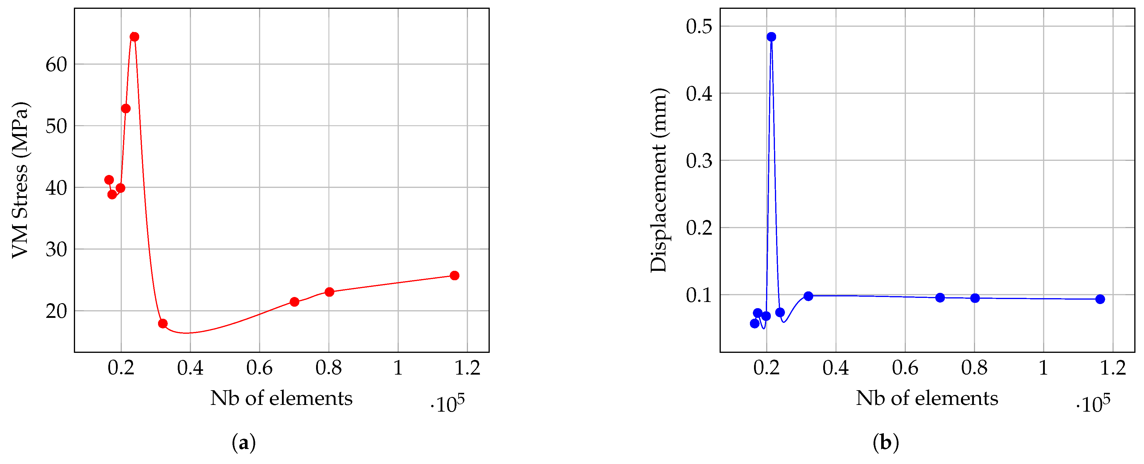
Mesh quality affects accuracy, so a convergence analysis determined the optimal mesh size balancing accuracy and efficiency. Von Mises Stress and Displacement were mesh-converged for the most precise outcomes. Because of their higher quality, quadratic hexahedral elements were used for all surfaces of both tubes and disks. The result of this Mesh convergence is displayed in
Figure 7.
The meshing process began with a coarse mesh and progressively refined it for greater detail. Although it does not fully converge, the analysis showed that stress values exhibited minimal variation beyond 40,000 elements. On the other hand, displacement values converged rapidly after 30,000 elements. Given this, a mesh consisting of 60,000 elements has been selected to ensure an adequate level of precision for a first analysis. This choice enables us to obtain a first order of magnitude for the results for subsequent analyses in this preliminary study, capturing the MAV’s structural behavior during its mission.
4.1. Static Analysis
The MAV experiences a maximum of 15 G forces in the Z-axis (transverse to the MAV), along with up to 2.2 G forces in the X and Y axes [
6]. The first analysis assesses two materials: an all-aluminum structure and a CFRP structure. By evaluating their performance under designated loads and conditions, the analysis aims to determine their suitability for the MAV’s primary structure.
4.1.1. Stress and Displacement Analysis
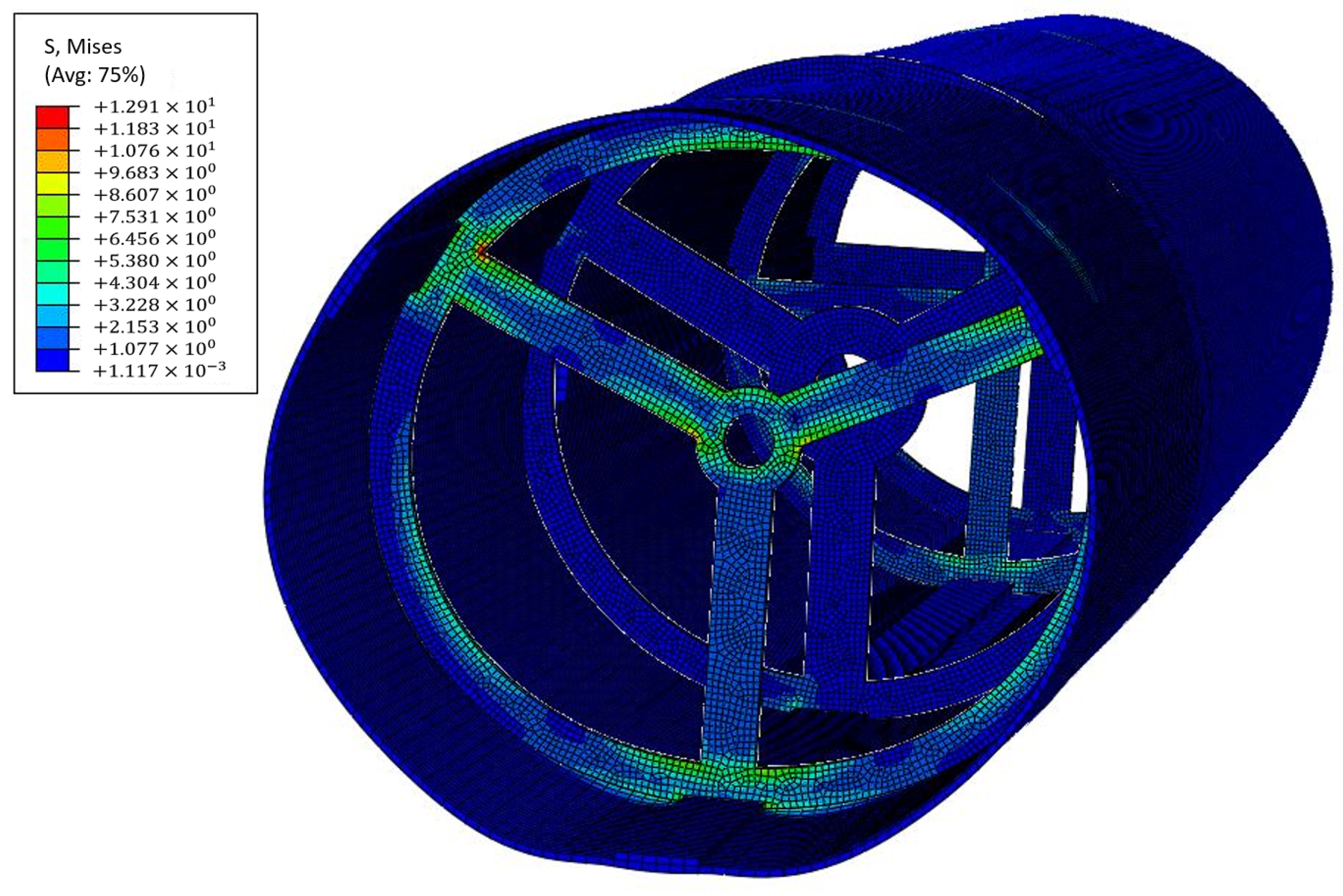
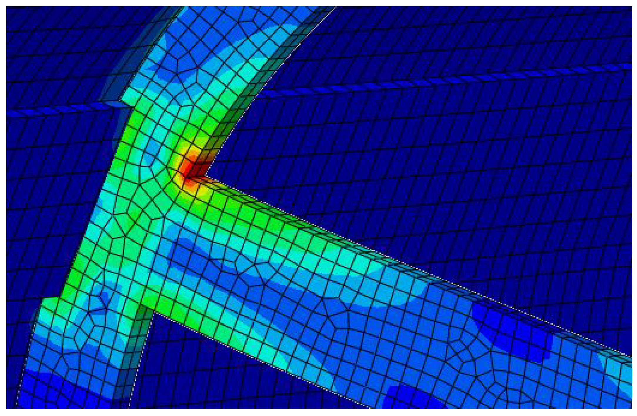
The stress analysis aims to prevent concentrated stresses in the structure exceeding the material yield strength. A safety factor greater than 1.5 between the maximum stress and yield strength is required for compliance. The initial analysis involves a 5 mm thick aluminum structure. A 15 G load is applied in the Z-axis. The result is shown in
Figure 8 and
Figure 9:
Upon analysis, the structural disks significantly absorb the transverse 15 G load, providing effective support to the rocket tube and preventing high bending loads that could negatively impact the interstage.
The primary stress concentration occurs at the interface between the rocket tube’s ribs and the structural disk, particularly in the second-stage structural disks. The second-stage disks, with their three-arm configuration, exhibit slightly lower strength compared to the four-arm design used in the first stage. Consequently, they experience higher stress levels at the surface in contact with the tube, as illustrated in
Figure 9. The upper part of the disk tends to warp under the load, resulting in elevated stress in the joints. However, due to the robustness and thickness of these components, the stress remains within safe limits. The maximum Von Mises stress is estimated at 12.91 MPa, significantly below the yield strength of the chosen aluminum material. There are no concerns about compromising structural integrity under these conditions.
Furthermore, the structure encounters a peak displacement of 0.15 mm, which is negligible when compared to the overall size of the model, with a tube of 2.6 m long. This maximal displacement is noted at the upper segment of the tube (opposite to the embedded boundary conditions). Despite the tube displaying slight bending, the load’s magnitude is insufficient to constitute a substantial concern.
Under the +Y and +X G-Loads, the disks warp; however, due to the relatively moderate load magnitude, the stress levels in the disks are not significantly high, with a maximum stress of approximately 8.75 MPa and 3.55 MPa observed for, respectively, +Y and +X loads, both at the base of the disk. Similar observations are made for the displacement, where it remains below 0.15 mm, confirming the structural stability and adequacy for the mission requirements.
4.1.2. Design Optimization
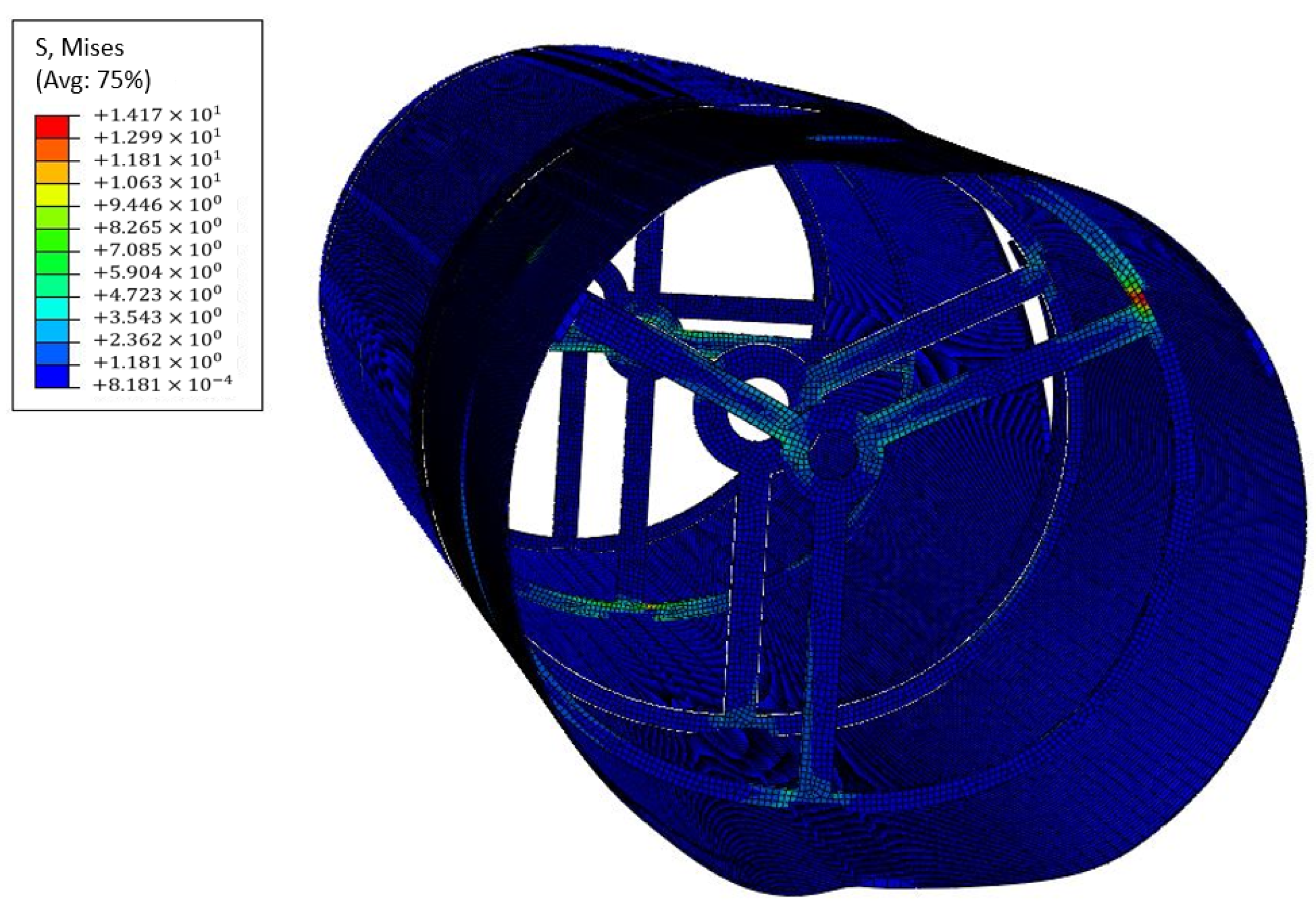
Several iterations were made with lighter structures to try to reduce the mass of the primary structure and therefore the overall GLOM. Two structures with 1.5 mm and 1 mm thickness were made and assessed in the same way.
These iterations display a similar behavior to the first analysis, as we can see in
Figure 10, with stress concentration still observed at the joints of the structural disks. As anticipated, the thinner structures experience higher loads, but they remain within acceptable limits, posing no threat to the structural integrity. It has been decided not to design structures with a thickness below 1 mm to adhere to the dynamic criteria defined in
Section 3.3, ensuring structural robustness to dynamic loads.
The mass of the different structures were assessed and gathered in
Table 7. While aluminum alloy shows great stiffness under static loads, its high density makes the primary structure quite heavy. Hence, the same tests are conducted with CFRP material. The analysis reveals that CFRP performs even better, as it demonstrates higher safety factors for stress with a lighter structure, much closer to the predictions made in the preliminary mass budget.
The results of the different iterations for each load case and thickness are gathered in the table available in
Appendix A. It must be noted that certain outcomes of the 1 mm thickness tube differ from what might be expected for a thinner configuration. Specifically, the analysis indicates lower displacements compared to the 1.5 mm variant. This divergence is likely due to the use of tetrahedral elements in meshing, prompted by the extreme thinness of the tube. Tetrahedral elements tend to represent material behavior less accurately than hexahedral elements, potentially explaining these discrepancies. Further mesh refinement shall be conducted.
However, the primary aim of this analysis was to ensure structural stability under the imposed loads. The model’s response implies that the 1 mm tube can withstand the loads without compromising structural integrity. While specific displacement values may be less accurate due to meshing constraints, the overall structural behavior suggests adequate performance under the specified conditions.
In summary, the combination of a thin tube and CFRP’s stiffness yields a lightweight yet robust primary structure, and is well-equipped to handle static landing loads. Nevertheless, the structure’s resilience against dynamic loads must still be validated, which is a focus of the subsequent section.
4.2. Dynamic Analysis
The dynamic analysis evaluates the primary structure’s response to vibrations arising during the EDL phase. The objective is to prevent resonance with these vibrations, identify vulnerable points, and avert failure due to excessive resonance magnitudes. This study involves modal analysis to identify shapes and frequencies of primary modes, followed by Steady-State Dynamics Analysis to gauge resonance magnitudes.
Using the same CFRP material and boundary conditions as the prior analysis, the 1.5 mm thick structure will be examined due to mesh quality concerns in the 1 mm variant. Both structures are expected to behave similarly. With a target frequency of over 24 Hz for the designed structure and a safety factor of 1.5, the validated primary frequency should exceed 36 Hz.
4.2.1. Modal Analysis
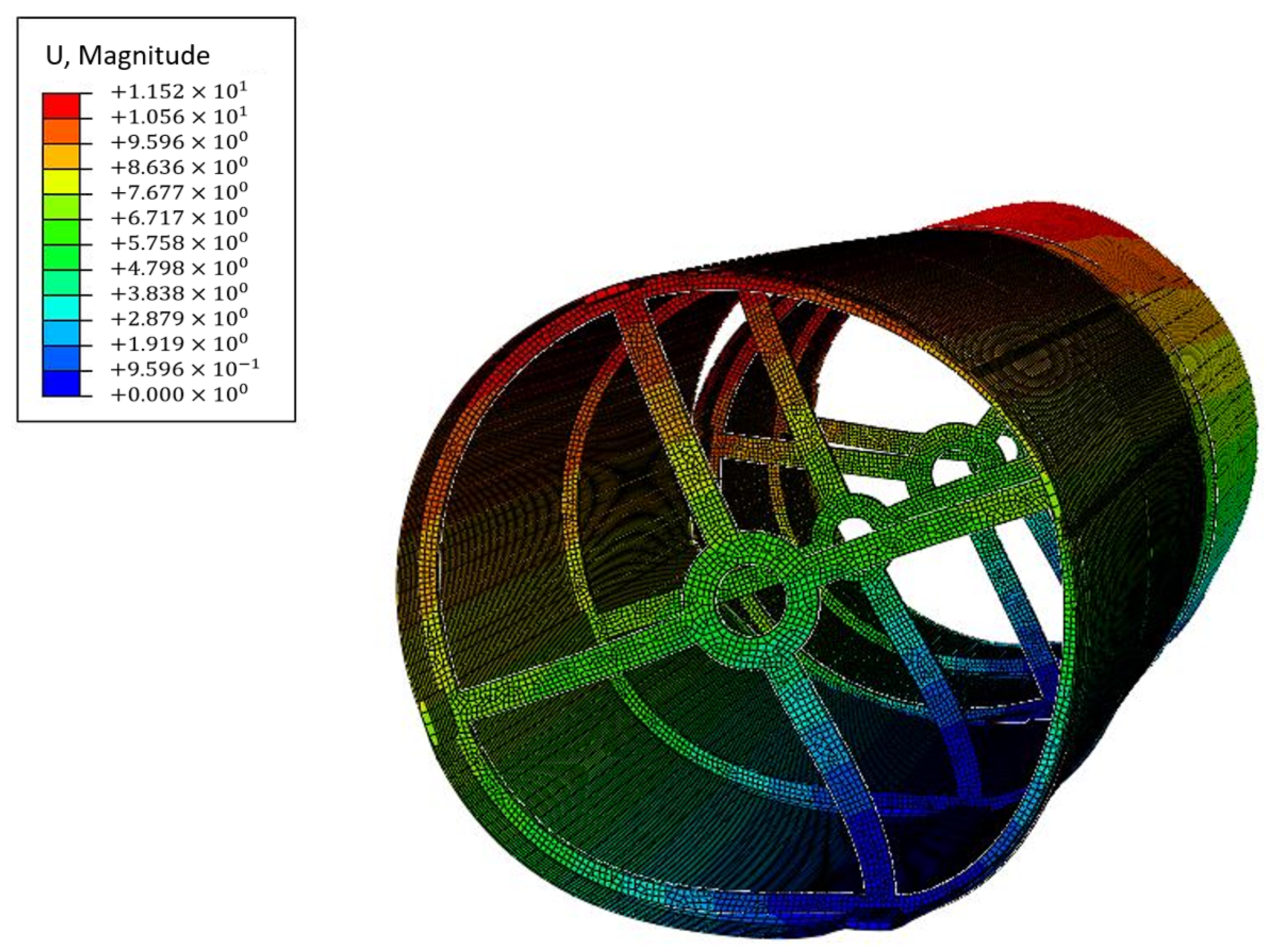
The results of the modal analysis for the primary structure are gathered in
Table 8 with the five first modes:
It can be noted that the primary frequency of 42.9 Hz is above the 36 Hz defined in the requirements which means it is unlikely to resonate with the vibrations of the landing.
As we can see in
Figure 11, the initial mode of the structure exhibits resonance in the +Y direction, highlighting a vulnerability at the base of the structural disks. To elevate this frequency, enhancing stiffness in this disk section would be necessary. Although the displacement magnitude of 11.5 mm is substantial and non-negligible, it does not offer definitive insights into the structure’s reaction to landing vibrations. Subsequent analysis will shed more light on the anticipated resonance behavior of the primary structure under those loads.
4.2.2. Steady-State Dynamics Analysis
In the context of steady-state dynamics, a CFRP damping factor of 0.03 is considered. This study involves three defined load cases, each imposing a static load in one of three reference frame directions: +X, +Y, and +Z. The +Y excitation, based on modal analysis results, is expected to induce more pronounced resonance. Load magnitudes correspond to those specified in the static analysis: 2.2 G in the +X and +Y directions, and 15 G in the +Z direction.
Figure 12 below depicts mode-displacement relationships for the highest-magnitude resonances.
Notably, the +X load predominantly excites the second mode, with a frequency response approximating 103.2 Hz and a displacement of 0.016 mm. The +Z load excites the second and seventh modes in similar proportions, yielding frequencies of 103.2 Hz and 166.8 Hz, with displacements of 0.077 mm and 0.082 mm, respectively. These resonances do not result in significant structural deformations.
As expected, the +Y load aligns with the first mode, generating a higher displacement of approximately 0.28 mm. While still negligible, this displacement warrants consideration. Reinforcing the disks to enhance stiffness might be advisable if future scenarios foresee higher loads in the +Y direction.
5. Results and Discussion
This article focuses on the preliminary design and structural analysis of a two-stage Hybrid MAV in the scope of the Mars Sample Return Mission. Compared to NASA’s Two-Stage Solid Rocket, this European MAV shows great engine performance and low Gross Lift-Off Mass. Various MAV concepts were evaluated including NASA’s proposals. While hybrid propulsion was often recognized as the best candidate for the mission due to its inherent advantages, it was often discriminated against due to its lack of maturity at the time [
18]. Sizing countered these concerns, adopting a two-stage configuration based on HyImpulse’s engine data. A compliance matrix summarizing the work performed in this study is displayed in
Table 9.
The resulting MAV boasts a GLOM of 292.8 kg, significantly below the 400 kg limit specified in REQ-SYS-03. The proposed hybrid rocket is configured to achieve the desired orbit with the OS payload, adhering to the space constraints outlined by the SRL. In terms of structural integrity, the FEA validated the rocket’s capability to withstand EDL, demonstrating a lightweight structure of 13.4 kg, equipped to endure landing loads with a safety factor above 5 and exhibiting a primary frequency of 42.9 Hz. However, critical aspects of the mission still need to be addressed for this design to achieve full functionality from a preliminary design standpoint. Several aspects were not addressed during this study, yet they are crucial to the mission’s success. Although the choice of thermally resilient materials may facilitate the MAV’s survivability and launch readiness, these capacities of the vehicle need to be properly addressed in each component.
The design of pivotal components such as avionics, the TCS, and the TVC aims to address unmet requirements. Efforts were made on implementing a LITVC system for the TVC, as illustrated in
Figure 3. A thorough trajectory simulation is underway, involving TVC selection and design considerations. Concurrently, ongoing analysis of mass distribution remains crucial for achieving greater mass savings in this two-stage configuration.
In addition to the TVC, the design of the TCS stands as a critical element requiring further study. Maintaining appropriate temperatures for components such as avionics and piping systems is imperative for mission success. Investigations are in progress to develop a versatile patch heater primarily utilizing conduction as the main heat mechanism. Equally important is the proper design of the rocket’s avionics. While an inventory of required materials is underway, the design must align with meeting REQ-SYS-01 and REQ-SYS-02.
It is worth noting that complying with the dimensional constraint is likely the most challenging requirement. Extending the MAV’s length would significantly benefit it by improving the L/D ratio, subsequently enhancing the performance of the propulsion system. However, this requirement is likely up for discussion as the SRL is not yet fully designed [
23]. Other minor adjustments for requirements such as REQ-MIS-01, REQ-MIS-02, REQ-MEC-03, and REQ-MEC-04 will not compromise the proposed concept’s ability to fulfill its mission.
A summary of the principal characteristics of the designed Hybrid MAV, compared to NASA’s current solid fuel concept, is provided in
Table 10.
These figures are approximations derived from the available documentation regarding NASA’s solid fuel MAV concept. It is reasonable to anticipate that NASA’s design teams will refine these numbers through further iterations. Nonetheless, the hybrid concept remains a strong candidate for MSR. In addition to offering a reduced GLOM and enhanced efficiency compared to NASA’s concept, the Hybrid MAV boasts several advantages. These include the use of a more environmentally friendly propellant, a decreased risk profile, improved propellant storability with less stringent thermal requirements, greater flexibility, and cost-effectiveness. The maturity level of this solution needs significant improvement to be a convincing competitor to NASA’s solid fuel MAV. However, the demonstrated performance shows promise and warrants further development.
6. Conclusions
While this design provides valuable insights into the potential performance of a Hybrid MAV, it is important to acknowledge that it is still a preliminary design. Given time constraints, certain sections were addressed swiftly, but a more in-depth analysis is required.
The analyses presented in this article are open to further refinement, which may involve incorporating additional parameters or utilizing more complex models with a finer mesh. For instance, the FEA conducted in this study does not consider the impact of temperature. The values presented in
Table 5 and
Table 6, utilized in the analysis, assume the mechanical properties of the materials at an atmospheric temperature of +20
C. However, this does not accurately represent the real landing conditions, which are expected to occur at significantly lower temperatures, as specified in the requirements. Additionally, the model’s precision requires improvement. The Von Mises stress does not reach full convergence beyond a grid count of 60,000. Further analyses ought to tackle this issue.
Similarly, the use of CFRP material in the analysis is an approximation that does not fully consider the influence of fiber orientation. The influence of fiber orientation was overlooked and must be addressed in a more detailed structural analysis. This oversight in material representation could affect the accuracy of the analysis and represents a significant point of improvement. The next step in FEA should be to simulate launch conditions from both Earth and Mars, considering their demanding nature. Additionally, conducting an acoustic study of the structure would help validate its integrity.
This paper aimed to propose a MAV concept utilizing hybrid propulsion, identify the challenges, provide solutions, conduct initial vehicle sizing, highlight the advantages of hybrid propulsion, design primary mechanical components like the primary structure, establish the rocket’s layout, and perform FEA to design a light and stiff primary structure which handles the landing loads. This is what was achieved during the formation of this paper. However, many essential aspects are yet to be included for a comprehensive preliminary design that yields a fully functional MAV. The missing components include trajectory simulations, thermal control, reaction control, and TVC design.
For a complete preliminary design, multiple design iterations are essential to optimize the vehicle. This is necessary to attain a considerable level of maturity, enabling it to stand as a credible alternative to NASA’s MAV concept. Once the MAV solution is well-defined and all requirements are completely met, constructing a prototype for testing becomes feasible. Achieving this milestone involves adapting the sizing and performance of the actual MAV to simulate Martian launch conditions on Earth.
Lastly, budget concerns, as referenced in [
23], have cast uncertainty on NASA’s proposed timeline for the MSR. Both the SRL and SRO components are taking more time and budget than initially projected [
23]. Given the multi-phase nature of the mission, a thorough investigation into the interface between the SRL and the MAV becomes imperative. Several crucial aspects of the MAV, such as its height, diameter, attachment points for transmitting landing loads to the structure, and the required temperature from the SRL’s igloo for MAV protection, are heavily reliant on the SRL’s design. Subsequent work on the MAV design should align with the evolving stages of the SRL which is currently in its early design phase.
This preliminary design study conducted in collaboration with the German space launch company HyImpulse shows that there is an opportunity for European entities to propose a more cost-effective, less complex, and more competitive MAV for the MSR that is potentially developed by a European company.
