Article

Experimental Investigation on the Control of Hypersonic Shock Wave/Boundary Layer Interaction Using Surface Arc Plasma Actuators at Double Compression Corner

1
College of Aerospace Engineering, Nanjing University of Aeronautics and Astronautics, Nanjing 210016, China
2
Hypervelocity Aerodynamics Institute of China Aerodynamics Research and Development Center, Mianyang 621000, China
3
National Key Lab of Aerospace Power System and Plasma Technology, Air Force Engineering University, Xi’an 710038, China
*
Authors to whom correspondence should be addressed.
Aerospace 2023, 10(12), 1016; https://doi.org/10.3390/aerospace10121016
Submission received: 19 September 2023 / Revised: 2 December 2023 / Accepted: 4 December 2023 / Published: 6 December 2023
(This article belongs to the Special Issue Shock-Dominated Flow)

Abstract

:
Compression corner shock wave/boundary layer interaction (SWBLI) is a typical shock wave/boundary layer interaction (SWBLI) problem in supersonic/hypersonic flows. In previous studies, the separation flow is usually caused by a single shock wave. However, in the actual aircraft surface configuration, two-stage compression or even multistage compression will produce more complex SWBLI problems. The multi-channel shock structure makes the flow field structure more complicated and also puts forward higher requirements for the flow control scheme. In order to explore a flow control method for the double compression corner shock wave/boundary layer interaction problem, an experimental study is carried out to control the double compression corner shock wave/boundary layer interaction with a high-energy flow pulsed arc discharge array under the condition that the incoming flow velocity Ma 6.0 has both noise flow fields and quiet flow fields. The results show that when UDC = 0.5 kV actuation is applied, the influence range of the hot gas mass flow direction is about 65 mm, which can weaken the shock wave intensity to a certain extent. When UDC = 1 kV actuation is applied, the influence range of the hot gas mass flow direction extends to 85 mm, and the actuation has a significant control effect on the flow field. Through spatio-temporal evolution analysis and spatial gradient threshold processing of high-speed schlieren images of actuated flow fields, the feasibility of controlling the hypersonic double compression corner shock wave/boundary layer interaction by using a high-energy flow pulsed arc discharge array is verified. The control law of a high-energy flow pulsed arc discharge array acting on the double compression corner shock wave/boundary layer interaction is revealed.

1. Introduction

In a supersonic flow, the disturbance of the air stream cannot propagate in the direction of the flow, so shock waves will inevitably exist in the process of deceleration and shock wave/boundary layer interaction (SWBLI) will inevitably occur in the interaction of the boundary layer on the surface of the aircraft body [1,2,3]. When the inverse pressure gradient induced by shock waves is large enough, the boundary layer will become thicker or even return inside, resulting in the boundary layer separating from the object surface, which will directly damage the aerodynamic performance of the aircraft. There are various forms of shock wave/boundary layer interaction in the outflow of the aircraft, including oblique shock wave/boundary layer interaction, normal shock wave/boundary layer interaction, and three-dimensional shock wave/boundary layer interaction, among which Compression Ramp-SWBLI is the most typical form of oblique shock wave/boundary layer interaction. It mainly occurs at the rudder surface of the aircraft [4,5].
At present, studies on CR-SWBLI control at a single compression corner have been extensive. For example, Verma and Chidambaranathan [6] adopted a stable microjet array for a single compression corner of 24° and found that jet spacing of 13 d has a better effect on reducing the size of pressure in the separation region. The 135° jet achieves a better control effect on the instability of separated shock waves. Verma compared the vortex generators of two positions and two configurations and found that the closer the interaction region is, the better the effect of the vortex generator on weakening the instability of the separation shock wave and reducing the intensity of the separation shock wave. The vortex generator with the configuration of s = 0 significantly reduces the root-mean-square value of the separation region. There is relatively little research on double compression Ramp-SWBLI and it mainly focuses on numerical simulation [7,8]. Durna et al. [9] studied the influence of the second order wedge angle on the flow field structure under Mach 7 conditions through numerical calculation. The results show that when the first-order wedge angle = 30° remains unchanged, the vortex structure has a more and more significant effect on the flow with the increase in the second-order wedge angle. Estruch-Samper et al. [10] conducted detailed experimental studies on Micro-Vortex generators of different heights, and the results show that when the height of the Micro-Vortex Generator is relatively small, it can inhibit flow separation. When the ratio of the height of the Micro-Vortex Generator to the boundary layer is about 0.3, the separation is effectively suppressed and the large-scale unsteady characteristics of SWBLI are significantly reduced. Babinsky et al. [11] also conducted an experimental study on the control details of the separation region through micro-ramps and found that when micro-ramps were used to disturb the flow field in supersonic inflow with Ma = 2.5, the flow separation caused by SWBLI could not be completely suppressed under the control of micro-ramps of all sizes but that micro-ramps could break the separation region. The space size is reduced to a plurality of broken small separation regions. Tong et al. [12] conducted a direct numerical simulation of a double compression corner with Mach number 2.9, the angle of the two stages was fixed at 12° and 24°, respectively, and studied the influence of the flow direction length Lc of the first stage on the flow field structure. It was found that with the increase in Lc, the size of the separation region is significantly reduced, the width of the Görtler vortex is reduced, and the directional coherence is enhanced [13,14,15].
As a passive flow control method without moving parts [16,17,18], plasma actuation can effectively avoid the increase in aerodynamic drag, flow loss, and other problems caused by the actuation itself, compared with micro-vortex generators, boundary layer venting, and other control methods. In recent years, due to the breakthrough of high repetition, frequency, energy, and array plasma actuation technology, its great potential in the field of supersonic flow control has been reflected. Preliminary studies have been conducted on dielectric barrier discharge, plasma synthetic jet, and surface arc discharge and other forms [19,20,21,22,23,24,25,26,27], particularly surface arc discharge [20]. In recent years, in the field of supersonic/hypersonic flow control, surface arc discharge plasma actuation (especially array-type surface arc discharge plasma actuation) has highlighted the advantages of strong energy injection, high frequency response characteristics, and flush with the wall surfaces [28,29]. Breakthrough progress has been made in shock wave control and shock wave/boundary layer interaction control [30,31].
Watanabe Y. et al. [32] examined the effect of the Reynolds number on plasma-assisted flow control. A linear dependency was found between the ramp pressure change per averaged plasma power and the Reynolds number. In addition, the effect of near-surface discharge on supersonic flow near 15° compression surface is studied by experiments and simulations [33]. Further simulations attempted to find an optimal range of plasma power and position in terms of achievable effect, effectiveness of the method, and response time of the system to the plasma actuation. Tang et al. [34] studied the evolution characteristics of high energy arc discharge actuation under a low pressure environment and used high-energy plasma actuation to effectively weaken the shock intensity of bow shock in front of a cylinder. In the incident shock wave/boundary layer interaction control, Luo et al. [35] found that both 5 kHz and 10 kHz high-frequency arc discharge actuation can weaken the intensity of separated shock waves and 5 kHz actuation can suppress the low-frequency motion of separated shock waves, while 10 kHz actuation can increase the low-frequency motion energy. Tang et al. [36] used spanwise array pulsed arc discharge actuation to achieve forced boundary layer transition and used high-frequency flow pulsed arc discharge array to achieve effective control of the shock wave/boundary layer interaction induced by the compression corner and proposed the corresponding conceptual model. Gan et al. [30] also realized the weakening of the intensity of separated shock waves in the shock wave/boundary layer interaction induced by the compression corner through high-energy and low-frequency array pulsed arc actuation.
In this paper, experimental studies on the control of double-compression corner shock/boundary layer interaction flow fields by array plasma actuation under Mach 6 conditions are carried out, and the coupling evolution characteristics of the array surface arc actuation and hypersonic double-compression corner shock/boundary layer interaction flow fields are discussed and analyzed. The ability of plasma actuation to regulate the shock wave/boundary layer interaction is verified under Mach 6 conditions, and the corresponding control rules are finally summarized.

2. Experimental System and Model

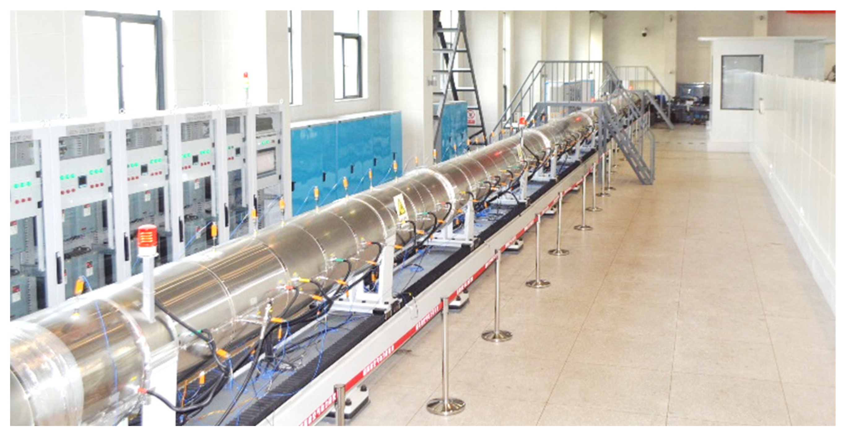
2.1. Hypersonic Quiet Wind Tunnel and High-Speed Schlieren System

The experiment is conducted in the Φ300 mm hypersonic quiet wind tunnel of the Hypervelocity Aerodynamics Institute of China Aerodynamics Research and Development Center. The experimental medium in the wind tunnel is air or nitrogen. The maximum design total pressure is 2.0 MPa, the maximum total temperature is 537 K, and the nozzle outlet diameter is 320 mm. The stable operation time of the wind tunnel is greater than 10 s, the duration of the static flow field is not less than 7 s, and the cycle of a single platform is 150~200 ms. The wind tunnel uses a Laval nozzle, and a special boundary layer suction device is set up in the upstream of the nozzle to realize the switch between the quiet flow field and the noise flow field. In quiet mode, the noise level of the Mach 6 flow field is 0.05~0.1% (adjustable), and the average Mach number is 6.03~6.15. The Mach number 8 flow field noise level is 0.07~0.1% (adjustable); that is, the sound pressure level is adjustable, the average Mach number is 7.90~7.95, and the uniform region diameter is not less than 240 mm. At the same time, the wind tunnel can operate in the conventional hypersonic Ludwig wind tunnel mode, and the noise level of the flow field is 2~3%, similar to that of the conventional hypersonic wind tunnel. The average Mach number is about 5.90, and the diameter of the uniform region is 200 mm. The main performance parameters of the wind tunnel are shown in Table 1, and the actual picture of the wind tunnel is shown in Figure 1. The actual flow conditions of the experiment are shown in Table 2, where the first row is the flow parameters of the static flow field and the second row is the flow parameters of the noise flow field.
Ma, Re/m, U, ρ, P0, T0, PS, TS, c, and N represent the incoming Mach number, unit Reynolds number, free flow velocity, incoming density, total pressure, total temperature, static pressure, static temperature, sound velocity, and the noise level.

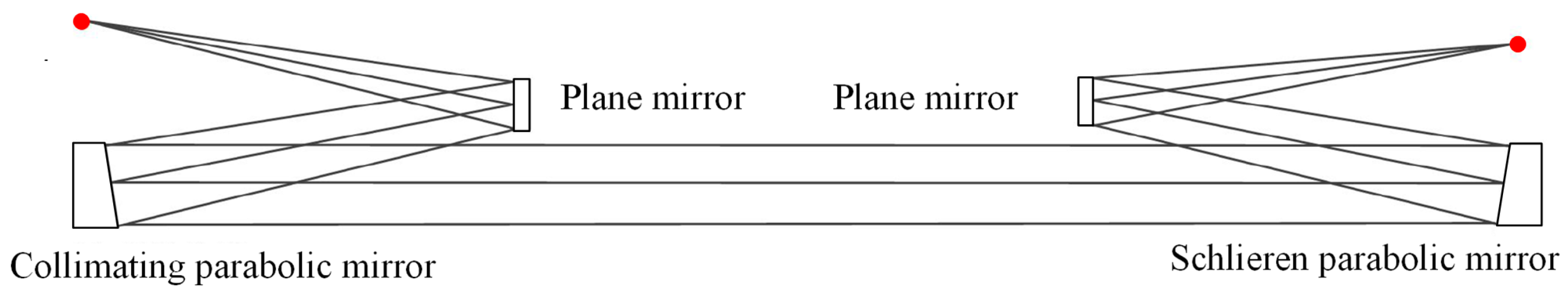
2.2. Schlieren System

A schlieren display technique is used to capture the flow junction in the experiment. Compared with the traditional schlieren system, the slit and knife edge of the optical system adopts the same side structure of the off-axis projectile target. The experimental schlieren system adopts the same side structure of the off-axis parabolic mirror, and the optical path of the Schlieren system is different from the traditional Z-type optical path. The optical path diagram is shown in Figure 2. The core of the system consists of four mirrors that reflect light. The maximum resolution of the experimental camera is 2048 pixel × 2048 pixel, the target size is 20.48 mm × 20.48 mm, the pixel size is 10 μm, and the schlieren frame frequency is 5 k. According to literature [37], in the same wind tunnel test, under Mach number 8, an exposure time of 5 μs is selected. In the discharge characteristic experiment, shockwaves and hot gas masses generated by plasma actuation can be obviously observed. In this experiment, under Mach number 6, the incoming flow velocity is lower, the brightness of the field of view is guaranteed, and a lower exposure time is selected to reduce the schlieren integration effect and field of view sharpness.

2.3. Experimental Model and Actuator Setup

The experimental model was installed in the wind tunnel test section and bolted to the bottom support frame. The experimental model used in this research is shown in Figure 1, which is divided into two parts: bottom plate and double compression corner. The diagram of the assembled flat-double compression corner is shown in Figure 3a. Figure 3b shows the actuator used in the experimental research of this paper, which is formed by three arc plasma actuators in series. Each discharge can generate three plasma actuations along the flow direction to expand the actuation range of the flow direction. Figure 3c shows the schematic diagram of the double compression corner model. The angles of the two folds are, respectively, 30° and 45°, and the total length is 55 mm. In order to meet the requirements of the strength check, it is necessary to control the overall weight of the experimental model, so the spanwise width of the corner model is designed to be 40 mm, while avoiding the side wall effect.
Before studying the control effect of a high energy drive, the discharge characteristics of the plasma arc discharge should be analyzed. Figure 4 shows the voltage and current waveform driven by high energy at a low voltage. As can be seen from the figure, the discharge time of a single pulse is not more than 20 μs, and when the voltage reaches a peak of about 8 kV, it will quickly drop to 0.8 kV. Compared with the voltage, the current rises and falls slightly behind, rapidly reaching a peak value of 110 A and then smoothly transiting to the initial value at the peak. Due to the presence of capacitors, it will decay at a relatively slow rate, and the discharge time will be extended. Finally, by integrating the current and voltage, it can be calculated that the single pulse discharge energy of the high energy arc is about 496 mJ.

3. The Reference Flow Field of Double Compression Corner Shock Wave/Boundary Layer Interaction at Ma 6.0

Firstly, schlieren measurements of a Ma = 6.0 noise flow field and quiet flow field are carried out. Compared with a Ma = 2.0 incoming flow condition [13], the corner leading edge under hypersonic conditions has a larger separation region. Figure 5a shows the instantaneous schlieren image under the noise flow field. It can be seen from the Figure that a typical SWBLI flow field structure and shock wave/shock wave interaction flow field structure are formed near the double compression corner. In Figure 5a, the flat boundary layer upstream of the corner is in a laminar flow state of linear growth, and the thickness of the boundary layer becomes obviously thicker along the flow direction. At the position of 100 mm in the flow direction, the boundary layer rises obviously, and a weak separation shock wave also appears outside the boundary layer here. From here to the point of impact between the boundary layer and the corner model is defined as the length of the separation region [9]. It is worth noting that the separation shock wave is not a clear straight line in the schlieren diagram, but there are weak compressed Mach waves in the plane region. Some research in the literature has simulated the separation region structure of an SWBLI compression corner at Ma 2.0 supersonic inflow by numerical simulation and found that the separation region is not strictly a two-dimensional structure but has certain three-dimensional characteristics. It is speculated that the shape of the separation region at Ma 6.0 is similar to it and also has certain three-dimensional characteristics. At the impact point between the boundary layer and the corner, a strong reattachment shock wave appears due to airflow compression, the separation shock wave passes through the reattachment shock wave, and there are more complex reflections behind the wave. At the leading edge of the second corner, as the turning angle of the airflow increases by 15° from the first corner to the second corner, the airflow is strongly compressed, and a second intense shock wave is formed here. When the first reattachment shock wave collides with the second shock wave, strong mutual interaction occurs. On the one hand, they intersect to form a stronger shock wave, and on the other hand, a weaker reflected shock wave is formed downward. There is a slip line between them. The slip line here is clear and obvious, indicating that the speed difference between the two regions is large.
Figure 5b is the time-mean schlieren diagram of the noise flow field based on 500 instantaneous schlieren gray value averaging processing, according to which we can carry out a qualitative analysis of the above flow field structure. It can be seen from the figure that not only the boundary layer, separation shock wave, reattachment shock wave, and interaction point can be well presented but also the complex reflection process of the separation shock wave after the reattachment shock wave can be well presented, which indicates that the result of the time-mean schlieren has good reliability. Therefore, we can examine the size of the separation region in the time-mean schlieren. As shown in the Figure, the white dashed line represents the separation shock wave. According to the definition of the boundary layer separation region above, it can be concluded that in the Ma 6.0 noise flow field, the length of the separation region is 62.5 mm.
In the quiet flow field, the basic structure of the flow field is the same as that of the noise flow field, but the spatial position of each structure does not present a small difference. As shown in Figure 6a, in the quiet flow field stage, excluding the interaction of external factors, the separation starting point of the boundary layer at the leading edge of the corner is greatly advanced, appearing about 85 mm from the flow direction, and the size of the separation region increases significantly. Not only does the initial position of the separation shock flow advance but also the height of the normal direction increases. The angle of the reattachment shock wave decreases slightly, so the normal height of the shock wave interaction point decreases. The morphological characteristics of the intense shock wave, reflected shock wave, and the angle of the slip line produced after the intersection of shock waves hardly change, but the position and length of the wave do change. Similarly, some qualitative rules can be obtained by analyzing the time-mean schlieren diagram of the quiet flow field. As shown in Figure 6, the size of the separation region increases to 90 mm, and the size of the separation region increases by 44% compared to the noise flow field. It can be seen that under hypersonic conditions, the size of the separation region in the quiet flow field will be larger, while in the actual hypersonic flight process it is usually faced with a small noise flow field with a low Reynolds number, and under the same configuration conditions, a larger separation region will be generated. Therefore, certain flow control means are urgently needed to regulate this problem. It should be noted that the size of the separation region in the quiet flow field is larger, which is not caused by the difference in Reynolds number. The main reason is that the quiet flow field is mainly laminar flow, which has a weak ability to resist the reverse pressure gradient and is easy to separate, while the noise flow field is mainly turbulence, which has a stronger ability to resist the reverse pressure gradient than the quiet flow field, so the separation scale of the quiet flow field is larger.

4. The Actuation Flow Field of Double Compression Corner Shock Wave/Boundary Layer Interaction at Ma 6.0

4.1. Analysis of the Control Effect

According to previous studies, even if the supersonic flow field can achieve a good control effect of high-frequency actuation, such as 5 kHz, 10 kHz, 20 kHz actuation, in the hypersonic flow field, the flow field disturbance frequency is high, far beyond the common high-frequency actuation range of plasma actuation. In addition, the extremely harsh incoming flow conditions make the plasma actuation with high frequency and low energy consumption unable to play a good control effect. Therefore, in order to regulate the strong SWBLI and shock wave/shock wave interaction in the hypersonic flow field, we naturally take into account the lower actuation frequency but use high-energy actuation with greater actuation intensity and more stable discharge. Therefore, in the experimental study of this section, a high-energy actuator with a capacitance of 1 μF and DC source voltage UDC = 1 kV is used to control hypersonic noise flow field and static flow field. In order to reduce the energy consumption of arc discharge plasma actuation, and to expand the actuation range, the arc plasma actuator is arranged into two-channel streamwise; that is, two plasma discharge positions are arranged along the flow direction of the flow field. Since the frame rate of the schlieren shooting was 5000 fps, the actuation frequency was still set at 480 Hz, and the schlieren images with different phases after actuation are selected to form the schlieren sequence.
Figure 7 shows SWBLI schlieren sequence of the noise flow field controlled by high-energy actuation. As shown in Figure 7a, after the discharge channel is established, due to the low static pressure of incoming flow, the two arc actuation fuse into one actuation and inject energy into the gas on the surface of the plate to induce a large volume hot gas mass. Compared with the two smaller hot gas masses separated, this not only enlarges the range of actuation but also increases the intensity of actuation and improves the control effect of actuation.
In Figure 7b, the shock wave induced by actuation changes into a hemispherical hot gas mass, and the leading edge reaches the foot of the separation shock wave. The hot gas mass inside the shock wave is coupled with the laminar flow boundary layer, resulting in increased disturbance. However, the state of separation shock at this phase has not changed. As shown in Figure 7c, when the hot gas generated by the actuation flows near the separation region, n the one hand, the separation region of the leading edge of the corner is completely covered by hot gas masses. Through observation of the state of the boundary layer, it can be found that the state of the boundary layer has changed, which is due to the shock wave and hot gas mass generated under the actuation of plasma, which disturbs the boundary layer. There is a vortex structure in the hot gas mass itself [38,39], and the interaction with the boundary layer will make the boundary layer also carry a vortex structure; these vortex structures also accelerate the fusion of the boundary layer and the main stream. At the same time, the hot gas mass generated by plasma arc discharge will be accelerated along with the incoming flow. At this time, the hot gas mass will encounter the boundary layer, especially the fluid with lower speed in the separation region, and momentum exchange will inevitably occur, making the low-energy fluid accelerate. At this time, the size of the separation region is greatly reduced, so the separation shock wave disappears.
In Figure 7d, after the hot gas mass flows through the surface of the plate, it is coupled with the boundary layer at the outer edge of the separation region and hits the surface of the angle model at this phase moment. It is found in the schlieren image that the boundary layer state changes, which is due to the mass, energy, and momentum exchange between the fluid and the hot gas in the boundary layer, which makes the boundary layer chaos intensified. However, at this stage, the boundary layer is hit by the hot gas mass and the boundary layer is in a chaotic turbulent state. The hot gas mass forms a virtual compression surface connecting the plate and the angle outside the boundary layer. Different from the traditional model bulge, the virtual compression surface formed by plasma actuation is an unsteady “bulge” formed by the shock wave and the hot gas mass in the flow field, which makes the attached shock wave “truncated” by the virtual compression surface and the shock foot move upward.
At the corresponding phase moment in Figure 7e, the hot gas mass has completely covered the surface of the corner of the first stage, and the virtual compression face is compressed ahead of the incoming flow. In addition, the impact point between the boundary layer and the model surface is still within the influence range of the hot gas mass and the virtual compression surface still exists, so the intensity of the reattachment shock waves is greatly weakened and the interaction points of the shock waves are dispersed. The unsteady motion of the reflected shock wave and the slip line also deviated from the original trajectory in the above process. Because the hot gas mass did not affect the second shock wave, the intense shock wave above the interaction point still maintained a large shock wave intensity.
Figure 7f shows the structural characteristics of the flow field when the hot gas mass actuated by the plasma passes near the corner of the second stage, as shown in the figure; at this time, the hot gas mass has passed the corner of the first stage, and the boundary layer also recovers the reference state, so the separation shock wave reappears and the related structure of the seconded shock wave also reappears. A complex flow structure appears behind the attached shock wave. Due to the action of hot gas mass, the second shock wave is dispersed by the hot gas mass and it is impossible to distinguish the flow structure, such as the disturbance point and slip line, in the flow field. According to the experimental results, the plasma arc discharge produces shock waves and hot gas mass, and an impact effect is one of its characteristics. Through the shock wave, the shock wave is affected and the intensity is reduced. This also reduces the inverse pressure gradient of the boundary layer, thereby indirectly reducing the separation region, which also plays an indirect role in separation control. According to the above analysis, high-energy arc plasma actuation can play an effective role in regulating SWBLI noise flow field and shock wave interaction.
In the quiet flow field, the incoming flow has a small disturbance. As can be seen in Figure 8a,b, the hot gas mass and shock wave induced by plasma actuation are similar to those in Figure 7. However, the coupling effect with the boundary layer does not introduce a large disturbance to the boundary layer. There is no large-scale vortex structure. At the corresponding phase moment in Figure 8c,d, the hot gas mass flows near the separation region. Based on the analysis of the reference state of the quiet flow field above, we know that the size of the separation region is larger than that of the noise flow field and the range of the separation shock wave is also larger. In Figure 8e, the upstream separation shock structure reappears, and the attached shock wave almost completely disappears at this stage. Only part of the weak compression waves is attached near the corner wall, and the angle is similar to that of the first corner. The structure of the shock wave after bifurcation is more regular and there is no large oscillation after plasma actuation. At the corresponding phase moment in Figure 8f, the hot gas mass flows near the second corner, at which time the separation region reappears, the complete structure of the separation shock wave has been established, and the related structure of the attached shock wave foot also reappears, and the second shock wave is dispersed by the hot gas mass. Since the disturbance in the flow field is small, the complex flow field structure like that in the noise flow field is not formed. The Mach wave angle is smaller and closer to the surface of the corner model.

4.2. The Influence of Actuation Energy on Control Effect

In the previous section, discharge parameters of UDC = 1 kV and capacitance 1 μF were used to control the hypersonic noise flow field and static flow field, and a relatively ideal control effect was achieved. In this section, the control effect of high-energy actuation on the hypersonic double compression corner shock wave/boundary layer interaction and shock wave/shock wave interaction flow field under different actuation intensities will be explored by adjusting the DC source voltage and capacitance.
Under the condition of noise inflow, due to the large disturbance in the boundary layer, according to the experimental results of surface arc actuation to control hypersonic boundary layer transition, applying small actuation disturbance can provide a great control effect to the boundary layer, playing a “four or two” role. Therefore, firstly, the DC source voltage is set as UDC = 0.5 kV and the capacitance as 1 μF. The control effect of arc actuation on the shock wave/boundary layer interaction of the hypersonic double compression angle and low energy shock wave interaction flow field was investigated. Figure 9 shows the structural evolution sequence of the flow field after actuation control. Figure 9a,c,e on the left correspond to the instantaneous schlieren images of the hot gas touching the leading edge of the corner model, hot gas reaching the boundary layer reattachment point, and the hot gas covering the shock wave region, respectively. Figure 9b,d,f on the right are the corresponding images after longitudinal gradient processing. Longitudinal gradient processing is to enhance the contrast of the longitudinal image in order to better display the boundary layer and flow field structure. In this section, the three instantaneous images with representative phase moments are selected for analysis, which will not be described below.
In Figure 9a, the hot gas mass generated by actuation has a long flow coverage range. Its leading edge contacts the model at x = 165 mm, and its trailing edge is located at x = 100 mm. The influence range of the hot gas mass is about 65 mm, which is enough to cover the entire separation region of the leading edge of the corner under the condition of noise flow. Longitudinal gradient processing is used to observe the fine structure of the boundary layer and shock waves. As shown in Figure 9b, the structure of the hot gas mass becomes more chaotic after it is coupled to the boundary layer. At this time, the separation shock waves disappear, the structure of the secondary shock waves does not change significantly, and the shock interaction points and slip lines and other structures do not change. When the hot gas mass flows to the vicinity of the reattachment point, as shown in Figure 9c, it is obstructed by the corner, and the hot gas mass piles up into a bulge here. Then, the attached shock wave foot moves upwards. The density variation in the region behind the wave also increases, and the disturbance of the flow field increases. When the hot gas mass completely covers the shock wave region, as shown in Figure 9e, the secondary shock wave is dispersed, the region surrounded by the two shock waves is further reduced, and the interaction point moves down. It can be seen from Figure 9f that the reflected shock wave generated after the shock wave interaction disappears and the shock wave interaction is controlled by actuation, but the interaction point still exists and the main shock wave and the slip line after polymerization are still clear. This indicates that the actuation strength of the discharge parameter is relatively weak. Although it has a certain flow control effect on the flow field, its control effect on the shock wave structure and disturbance effect on the flow field need to be further improved.
When a higher intensity arc actuation is applied to the flow field, as shown in Figure 10, the output voltage of the DC source is set as UDC = 1 kV, and the capacitance is selected as 4 μF, the flow field structure produces a more intuitive and significant control effect. In Figure 10a, when the leading edge of the hot gas mass contacts the corner model, the trailing edge is still at the position of x = 90 mm, and the flow direction influence range is at least 80 mm. Compared with the above actuation intensity, the flow direction influence range of the hot gas mass has expanded at least 23.1%. It can also be seen from the instantaneous schlieren diagram that, compared with Figure 10a, under the same phase, the longitudinal height of the hot gas mass also increased slightly, indicating that the intensity of actuation greatly increased. As can be seen from the gradient processing diagram, the disturbance to the boundary layer caused by actuation also increased with the increase in the intensity of actuation, resulting in a change in the flow structure near the reattachment point. Although the hot gas mass did not flow to the reattachment shock wave, the shock wave foot already showed the characteristics of disturbance and deformation. At the phase moment when the hot gas mass covers the reattachment point, different from Figure 9, the volume of the hot gas mass is larger after accumulation, almost covering the entire corner of the first stage. Moreover, the structure of the reattachment shock wave completely disappears, weakening into several weak compression waves, and the position of the interaction point drops to almost close to the model surface or even disappears. As can be seen from Figure 10d, the weakened compression wave kinks together with the second shock wave, and there is a slip line backwards at the interaction point. At this phase, the secondary shock wave almost completely disappears, and the strength of the shock wave structure is greatly weakened. When the hot gas mass flows to the corner surface, all the shock wave structures are weakened into weak compression waves, as shown in Figure 10e,f. Compared with small energy actuation, large energy actuation can effectively weaken the intensity of shock waves in the flow field.
Because we focused on the control effect of actuation on shock waves, only the flow field image near the corner model was captured for gradient enhancement processing, and the control effect of the two actuation intensities is further compared. Figure 11 shows the enhancement diagram of the shock wave structure evolution gradient of the noise flow field after actuation. The above three pictures show the actuated flow field when the DC power output UDC = 0.5 kV and the output power is 2000 W, and the following three pictures show the actuated flow field when the output UDC = 1 kV and the output power is 4000 W. In order to facilitate the observation of the shock structure and the precise observation of the evolution process, x = 160 mm on the original coordinate axis of Figure 5, Figure 6, Figure 7, Figure 8, Figure 9 and Figure 10 is set as the origin of the new X-axis coordinate. Figure 11 shows the enhancement gradient diagram. Gradient enhancement is one of the means of image enhancement, mainly through the adjustment of image contrast; that is, the contrast intensity of light and dark. Since the schlieren image is mainly black and white toned, the gradient enhancement process is carried out. In addition, the black and white tone replacement is carried out to better reflect the flow field structure. Figure 11a,d corresponds to the phase moment of the hot gas mass touching the corner wall. It can be seen from the figure that although there is a small difference in instantaneous shock wave morphology, the flow field can still be identified as being in the same state. At this time, the hot gas mass has not had a regulating effect on the main structure of the flow field. When the hot gas mass flows to the vicinity of the reattachment point, the structure of the reattachment shock wave is still clear in Figure 11b, and the location of the interaction point of the shock wave is still clear. However, there is no structure of the reattachment shock wave in Figure 11e, and only the second shock wave and the converged shock wave have a clear structure. The structure of the other compression waves is not obvious, which also indicates that the density changes are small. The shock wave intensity decreases when the hot gas mass flows to the shock wave region; although the main flow field structure is no longer prominent in Figure 11c, the shock wave near the shock wave interaction point is still relatively clear. In Figure 11f, the overall structure of the flow field weakens and no clear interaction point appears, indicating that the actuation control effect is better.
When the high-energy actuation is applied to the hypersonic quiet flow field, it is similar to the noise flow field. The flow field structure of three typical phase moments is extracted for longitudinal gradient processing, as shown in Figure 12. The three images on the left are the actuated flow field when UDC = 0.5 kV, and the three images on the right are the actuation flow field when the output UDC = 1 kV. The control effect of different actuation intensities under the condition of quiet flow is compared and analyzed.
In Figure 12a,b, the coverage range of the hot air mass is slightly different from that under the noise inflow condition. When UDC = 0.5 kV, the flow range of the hot air mass is x = 107.5 mm~x = 167.5 mm, and the length is about 60 mm. The flow range of the hot gas mass increases to x = 90 mm~x = 167.5 mm, and the length is about 77.5 mm. Therefore, compared with the noise flow field, the influence range of hot gas mass in the quiet flow field is reduced under the two actuation parameters. Considering that the quiet flow field and the noise flow field are the same vehicle test, the discharge continues to the quiet flow field after the noise flow field is actuated. Continuous discharge reduces the output capacity of the power supply, which in turn reduces the influence range of the hot gas mass. However, it can be found that the influence range of the hot gas mass decreases slightly, which decreases by 7.7% and 3.1%, respectively, under the two actuation parameters, so this attenuation is ignored in this test study.
When the hot gas mass covers the reattachment point, Figure 12c shows that the control effect of the flow field under quiet actuation UDC = 0.5 kV is similar to that under noise conditions. The reattachment shock wave moves upward and the interaction point drops, while the flow structure near the interaction point hardly changes. However, the control effect of UDC = 1 kV actuation on the flow field is slightly different from that under noise conditions, as shown in Figure 12d. Unlike the shock wave bifurcation in Figure 9d, the reattachment shock wave here is weakened into a weak compression wave, and the control effect of actuation on the reattachment shock wave is better.
When the hot gas mass covers the shock wave region, Figure 12e shows that actuation plays a prominent role in controlling the interaction points, and the interaction points move down significantly, almost attached to the model. However, the structure of the shock waves, especially the structure of the secondary shock waves, is still clear. Figure 12f shows that higher intensity actuation has better control on the shock wave’s structure, no obvious interaction points exist, and the slip line almost disappears. The detailed features will be further analyzed and studied from local gradient enhanced images.
As shown in Figure 13, the local gradient enhanced images of the flow field after actuation with two kinds of parameters are compared. The structures in Figure 13a,d are similar, with clear flow structures such as secondary shock wave, second shock wave, interaction point, main shock wave after convergence, reflected shock wave, slip line, etc. The two images can be regarded as the state of the reference flow field. There are obvious contrast differences in the images at the second phase moment. Figure 13b shows that the flow field barely changes after UDC = 0.5 kV actuation is applied, and only some bending deformation occurs on the slip line, indicating that the interaction point receives high-frequency disturbance. Figure 13e shows that the secondary shock wave almost completely disappears, and the position of the interaction point moves down substantially. The control effect of the UDC = 1 kV actuation is remarkable. When the hot gas mass flows to the shock wave region, the interaction point is almost attached to the model surface in Figure 13c, but the structure of the attached shock wave and the main shock wave is relatively clear. However, in Figure 13f, only one main shock wave can be observed in the whole flow field, and the other structures are greatly weakened. It shows that the actuation of this parameter can effectively control SWBLI and the shock wave/shock wave interaction in the hypersonic quiet flow field.

5. Conclusions

In this paper, the research on dual compression corner shock/boundary layer interaction control is extended from supersonic to hypersonic, and an experimental study on dual compression corner shock/boundary layer interaction controlled by high-energy arc actuation (Ma = 6.0) is carried out to summarize the control law of dual compression corner shock/boundary layer interaction by arc plasma actuation under wide Mach number conditions. The specific research conclusions are as follows:
(1)
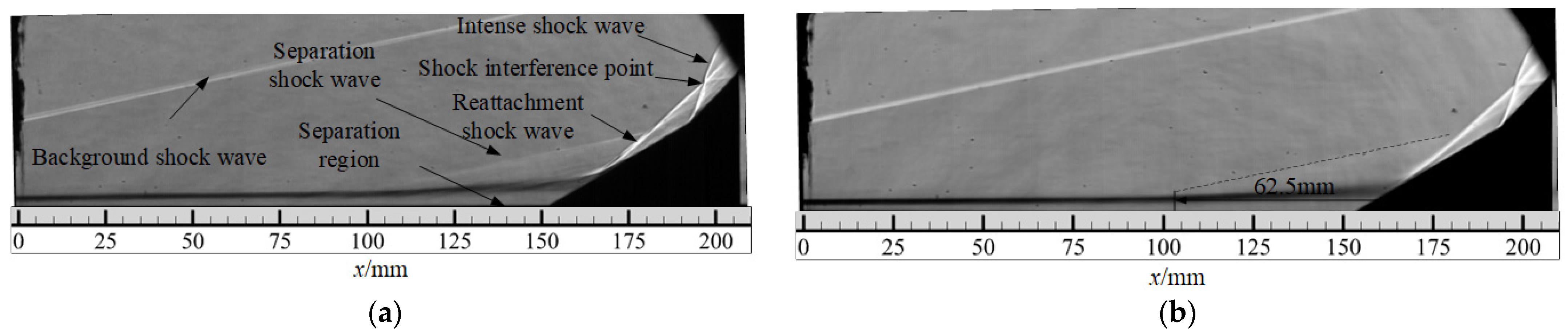
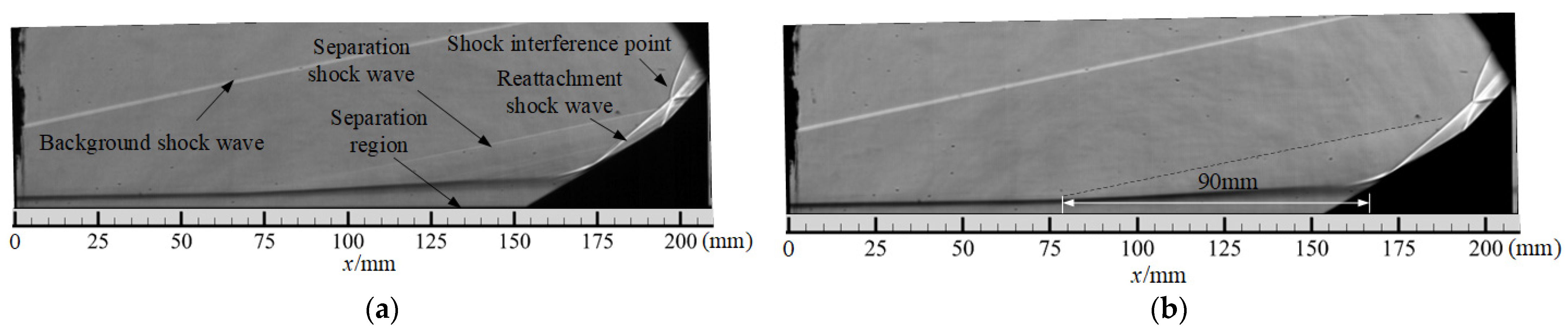
The flow field structure of noise incoming flow conditions is similar to that of quiet incoming flow conditions. Compared with Ma = 2.0 incoming flow conditions, the corner leading edge under hypersonic conditions has a larger separation region, and the size of the separation region is also affected by the level of incoming flow noise. By averaging the gray value of schlieren images, it is found that the length of the separation region is 62.5 mm under the condition of noise incoming flow and 90 mm under the condition of quiet incoming flow, which may be related to the disturbance in the incoming boundary layer. In the noise flow field, the disturbance in the incoming boundary layer is large and contains more vortex structures, which promotes the energy mixing between the boundary layer and the mainstream region. The ability of the boundary layer to resist separation is enhanced.
(2)
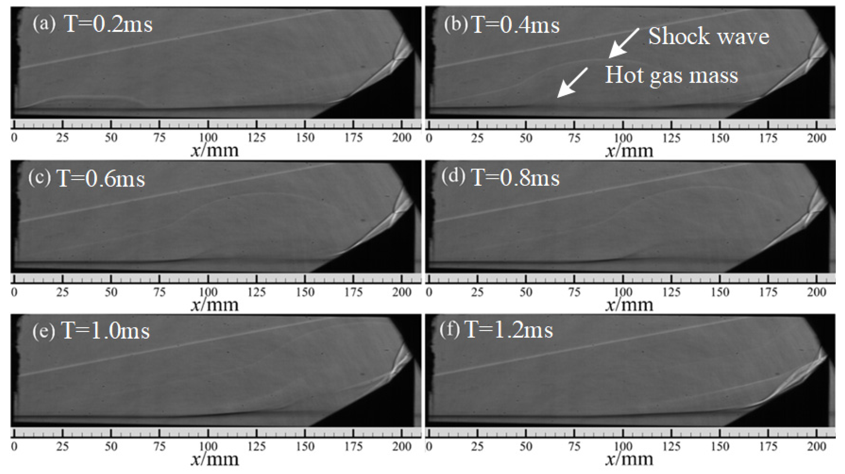
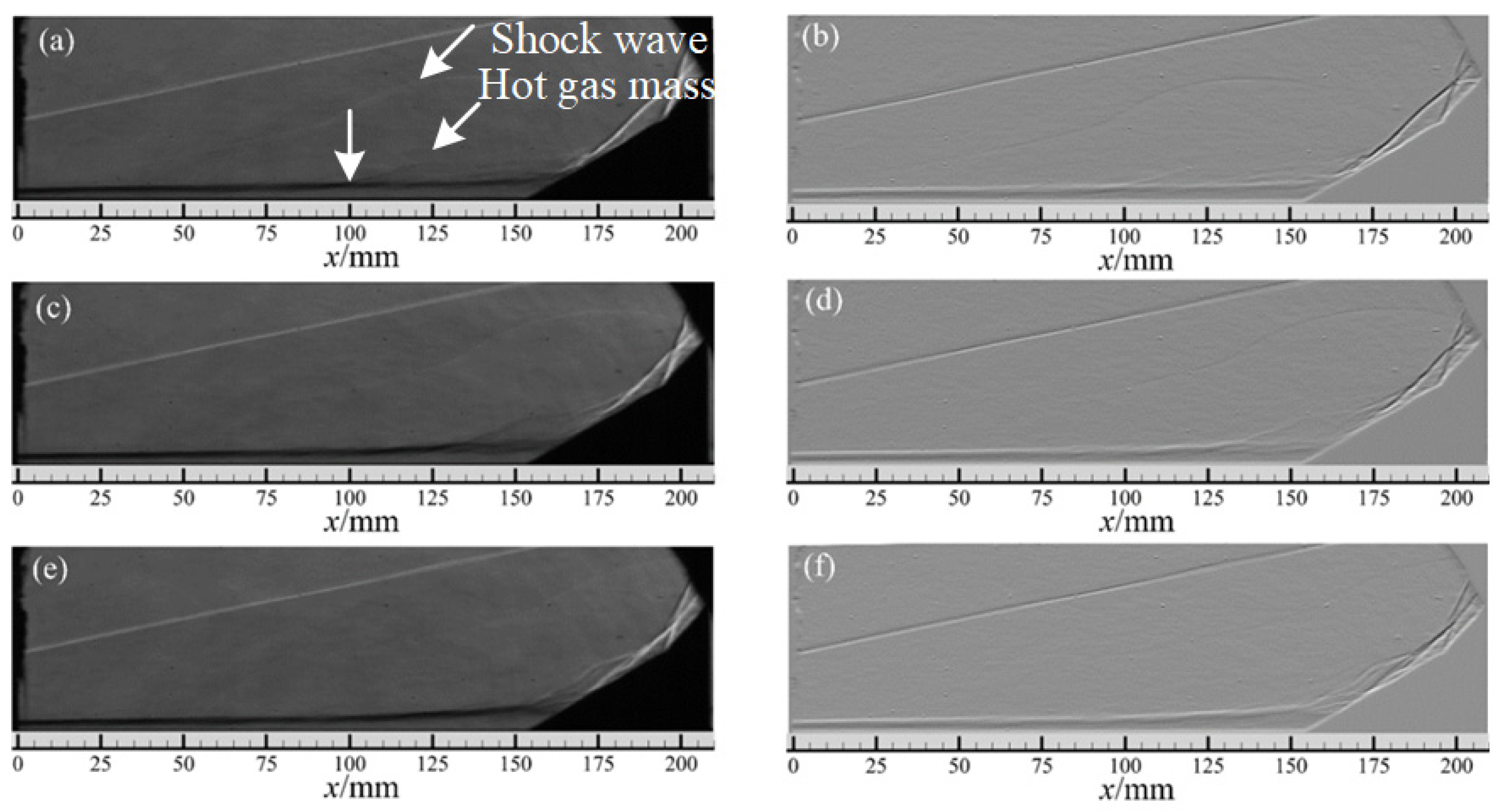
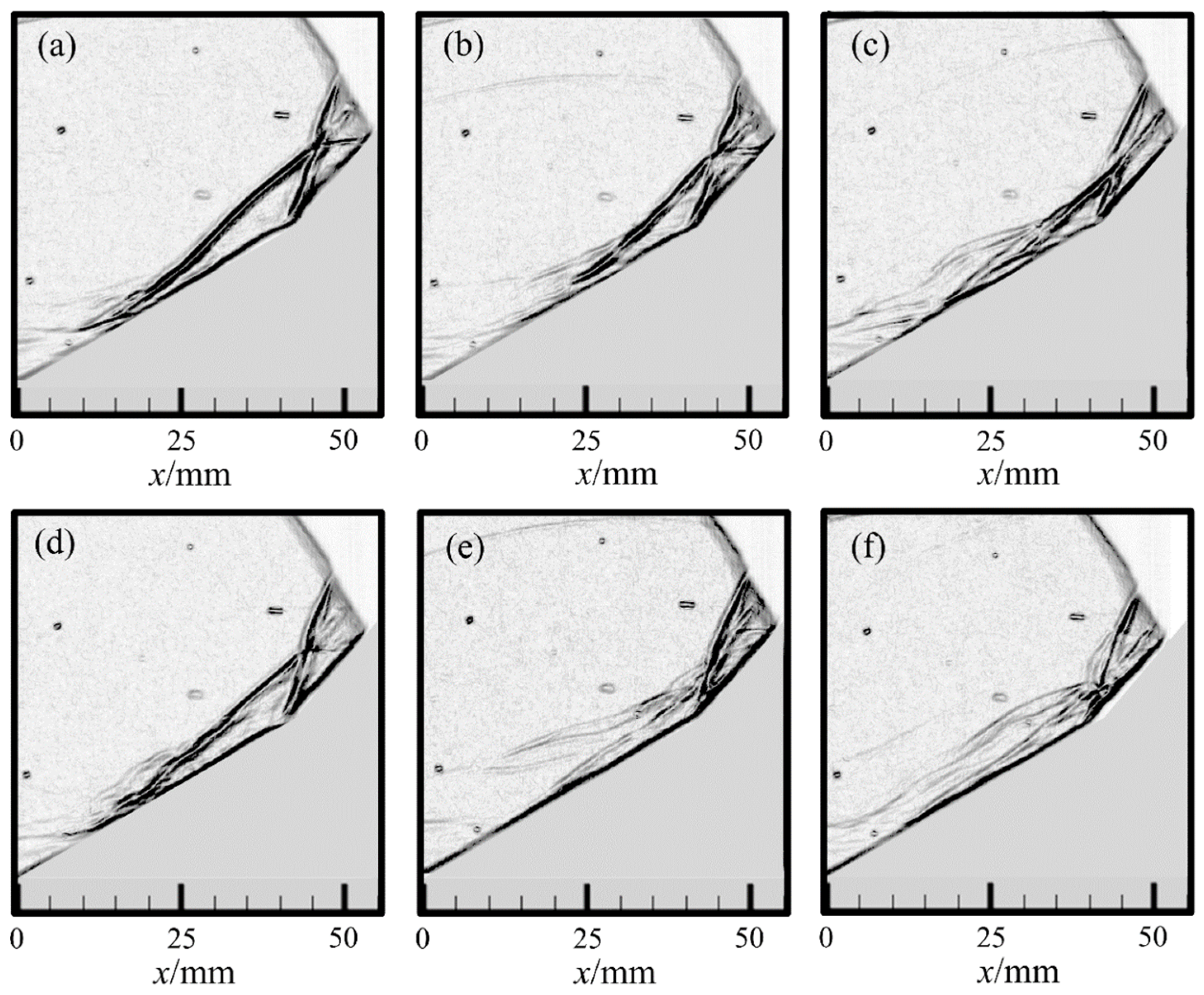
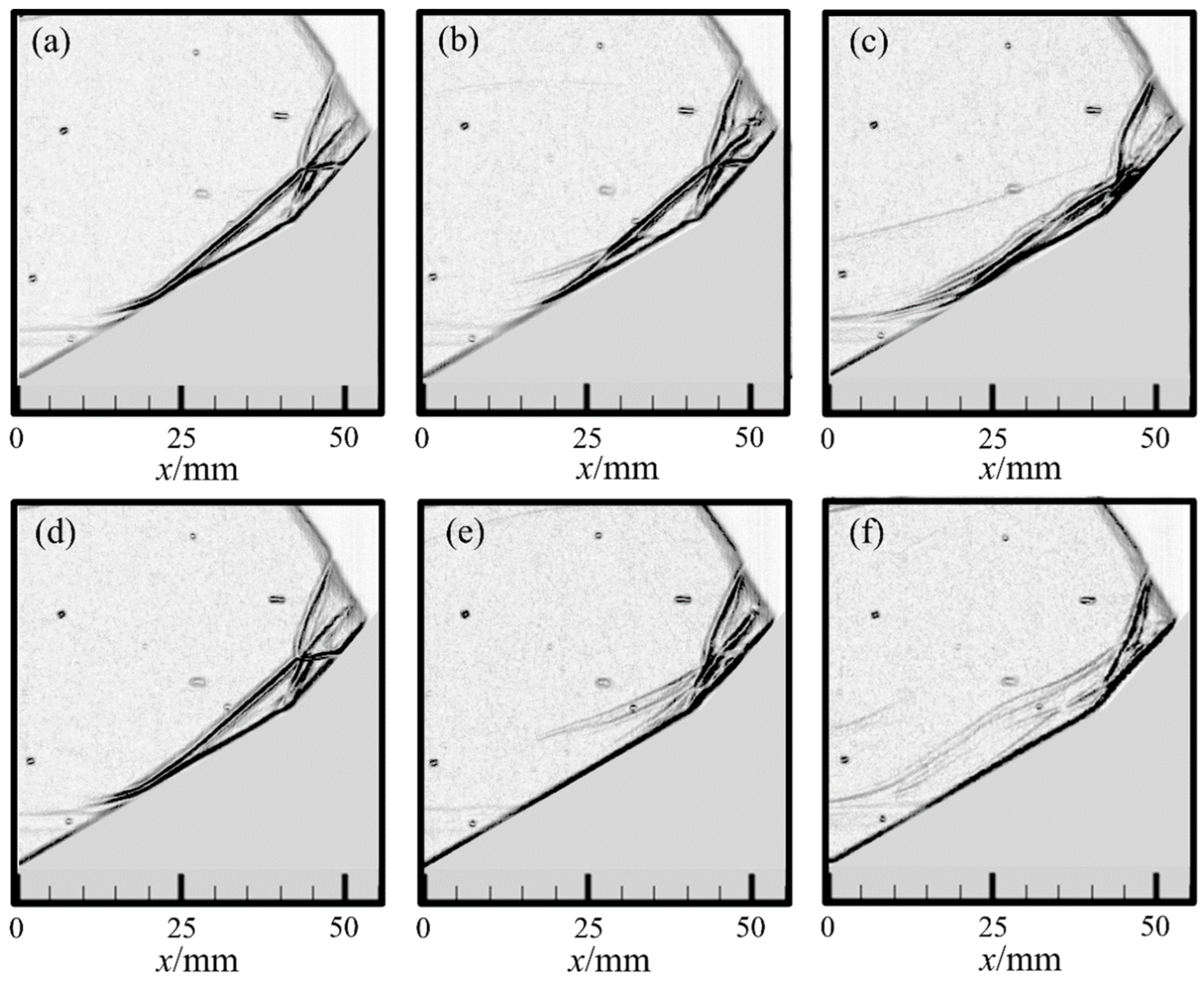
After the application of high energy arc actuation, the double compression corner shock wave/boundary layer interaction and the shock wave interaction structure under the two types of flow field can show the control effect of the shock wave disappearing and weakening under the control of hot gas masses. The hot gas mass first couples with the separation region near the leading edge of the corner, effectively promoting the momentum exchange between the boundary layer and the main flow region, and the separation shock wave weakens or even disappears. Secondly, when the hot gas mass passes through the reattachment shock region, as the reattachment region of the boundary layer is impacted by the hot gas mass, the reattachment shock wave forks and deforms, the shock wave intensity is greatly weakened, and then the interaction point of the shock wave fluctuates greatly, as well as the slip line and reflected shock wave. High-energy actuation has an effective control effect on the interaction flow field of the shock wave.
(3)
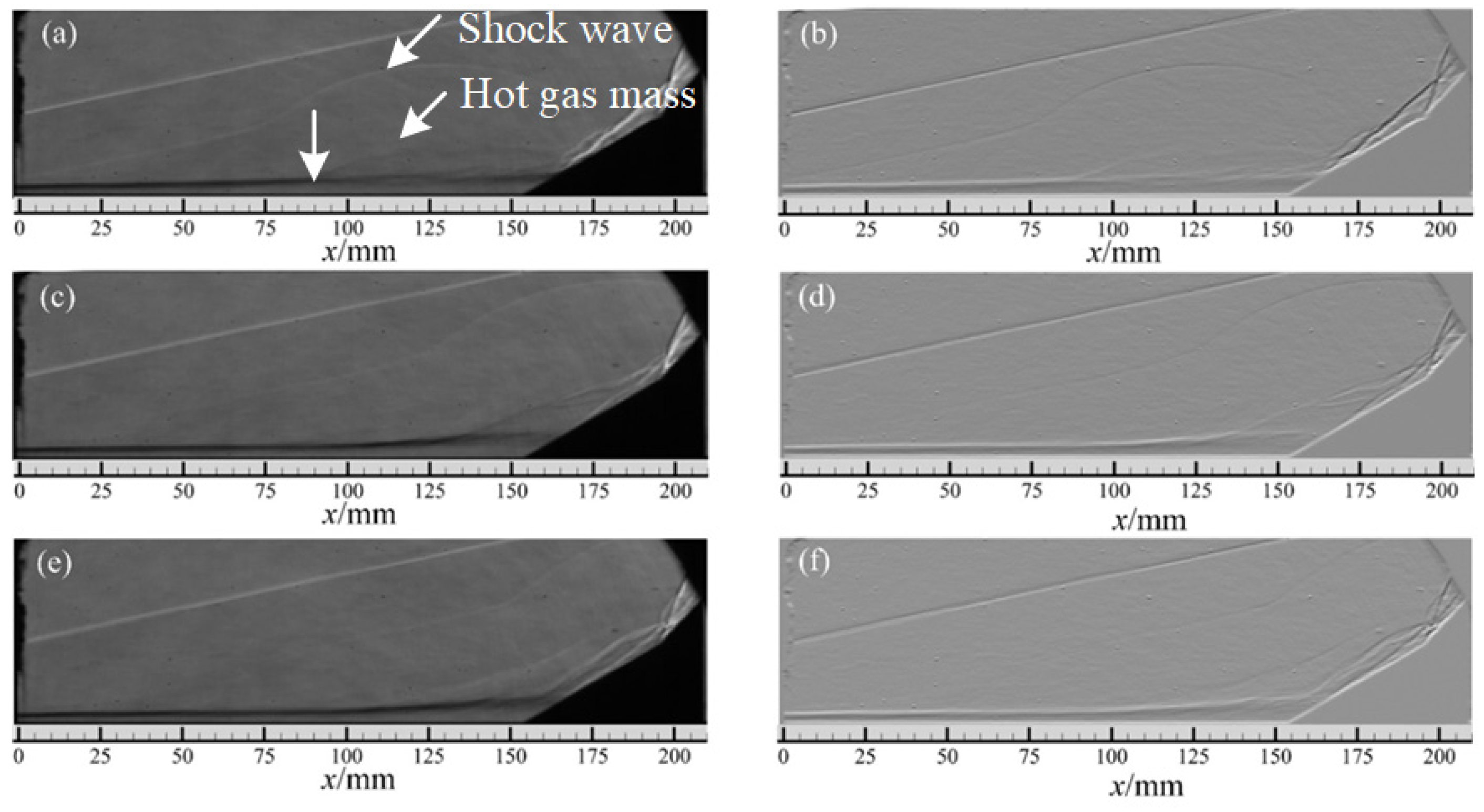
The evolution characteristics of the flow structures in the noise flow field stage and the static flow field stage are similar, and the control effect of high-energy actuation on the separation shock wave and the reattachment shock wave is different. On the one hand, the separation region in noise flow field is small, and the control effect of high-energy actuation on reducing the intensity of separated shock waves is relatively good. However, in the quiet flow field, the separation region is large and the range of separated shock waves is large, and the effect of actuation is not ideal. On the other hand, the disturbance in the noise flow field is large. When the hot gas generated by actuation passes through the reattachment shock wave, the reattachment shock wave is wavy after bifurcation, while in the quiet flow field the shock wave after bifurcation is scattered and linear. Plasma actuation plays a good role in controlling the wave system.
(4)
In the two types of flow fields, the higher the discharge energy is, the larger the influence range of the hot gas induced by actuation is and the better the control ability of arc plasma actuation on the hypersonic double compression corner shock wave/boundary layer interaction flow field is. When UDC = 0.5 kV actuation is applied, the influence range of the hot gas mass flow direction is about 65 mm, which can weaken the shock wave intensity to a certain extent, and the shock wave interaction point oscillates; thus, the shock wave interaction can be controlled. Although it has a certain flow control effect on the flow field, its control effect on the shock wave structure and the disturbance effect of the flow field need to be further improved. When UDC = 1 kV actuation is applied, the influence range of the hot gas mass flow direction expands to 80 mm, and the actuation has a significant control effect on the flow field. Even in the quiet flow field stage, the secondary shock waves almost completely disappear and the hypersonic double compression corner shock/boundary layer interaction and shock wave/shock wave interaction can be effectively controlled.

Author Contributions

Conceptualization, B.Y., H.Y. and C.Z.; methodology, B.Y. and H.Y.; software, H.Y.; validation, H.L., H.Y., N.Z. and D.Z.; formal analysis, B.Y.; investigation, H.Y.; resources, N.Z. and H.L.; data curation, D.Z.; writing—original draft preparation, B.Y., H.Y. and C.Z.; writing—review and editing, H.Y., N.Z., H.L. and D.Z.; visualization, C.Z.; supervision, H.L.; project administration, H.L.; funding acquisition, H.L. All authors have read and agreed to the published version of the manuscript.

Funding

This research was funded by the National Science and Technology Major Project (Grant No. J2019-II-0014-0035).

Data Availability Statement

The data and materials are available upon request.

Acknowledgments

Thanks to Jingqi Cao and Shaoyi Wang for their help in the experiment.

Conflicts of Interest

The authors declare no conflict of interest.

References

  1. Sebastian, R.; Schreyer, A.M. Control of SWBLI in a 24deg Compression Ramp Flow with Air-jet Vortex-generator. In Proceedings of the AIAA Scitech 2023 Forum, National Harbor, MD, USA, 23–27 January 2023. [Google Scholar]
  2. Kane, A.A.; Peetala, R.K.; Kulkarni, V. Investigation of pressure feedback technique to control ramp based SWBLI. Acta Astronaut. 2022, 201, 482–495. [Google Scholar] [CrossRef]
  3. Yang, S.Z.; Liao, K.; Xie, W.Z. Mechanisms of Hysteresis in the Acceleration and Deceleration Processes of Hypersonic Inlets. J. Aerosp. Eng. 2023, 36, 04023007. [Google Scholar] [CrossRef]
  4. Hoffman, E.N.; Kendhammer, D.M.; LaLonde, E.J. Effects of distributed roughness on shock-wave/boundary-layer interactions at Mach 7.2. In Proceedings of the AIAA Scitech 2023 Forum, National Harbor, MD, USA, 23–27 January 2023. [Google Scholar]
  5. Whalen, T.J.; Schöneich, A.G.; Laurence, S.J.; Sullivan, B.T.; Bodony, D.J.; Freydin, M.; Dowell, E.H.; Buck, G.M. Hypersonic Fluid–Structure Interactions in Compression Corner Shock-Wave/Boundary-Layer Interaction. AIAA J. 2020, 58, 4090–4105. [Google Scholar] [CrossRef]
  6. Verma, S.B.; Chidambaranathan, M. Transition control of Mach to regular reflection induced interaction using an array of micro ramp vane-type vortex generators. Phys. Fluids 2015, 27, 107102. [Google Scholar] [CrossRef]
  7. Sullivan, B.T.; Bodony, D.J. Direct Simulation of Fluid-Structure Interaction in Compression Ramp with Embedded Compliant Panel. In Proceedings of the AIAA Aviation 2019 Forum, Dallas, TX, USA, 17–21 June 2019. [Google Scholar]
  8. Sun, Z.; Gan, T.; Wu, Y. Shock-wave/boundary-layer interactions at compression ramps studied by high-speed schlieren. AIAA J. 2020, 58, 1681–1688. [Google Scholar] [CrossRef]
  9. Durna, A.S.; Celik, B. Effects of double-wedge aft angle on hypersonic laminar flows. AIAA J. 2020, 58, 1–15. [Google Scholar] [CrossRef]
  10. Estruch-Samper, D.; Vanstone, L.; Hillier, R.; Ganapathisubramani, B. Micro Vortex Generator Control of Axisymmetric High-Speed Laminar Boundary Layer Separation. Shock Waves 2015, 25, 521–533. [Google Scholar] [CrossRef]
  11. Babinsky, H.; Li, Y.; Pitt Ford, C.W. Microramp Control of Supersonic Oblique Shock-Wave/Boundary-Layer Interactions. AIAA J. 2009, 47, 668–675. [Google Scholar] [CrossRef]
  12. Tong, F.L.; Li, X.L.; Duan, Y.H. Direct numerical simulation of supersonic turbulent boundary layer subjected to a curved compression ramp. Phys. Fluids 2017, 29, 125101. [Google Scholar] [CrossRef]
  13. Zhang, C.B.; Yang, H.S.; Liang, H.; Guo, S.G. Plasma-based experimental investigation of double compression ramp shock wave/boundary layer interaction control. J. Phys. D Appl. Phys. 2022, 55, 325202. [Google Scholar] [CrossRef]
  14. Vatansever, D.; Celik, B. Unsteady shock interaction mechanisms of high enthalpy reacting flows over double wedges at Mach 7. Phys. Fluids 2021, 33, 056110. [Google Scholar] [CrossRef]
  15. Hao, J.; Wen, C.-Y.; Wang, J. Numerical investigation of hypervelocity shock-wave/boundary-layer interactions over a double-wedge configuration. Int. J. Heat. Mass. Transf. 2019, 138, 277–292. [Google Scholar] [CrossRef]
  16. Adamiak, K. Quasi-stationary modeling of the DBD plasma flow control around airfoil. Phys. Fluids 2020, 32, 085108. [Google Scholar] [CrossRef]
  17. Lago, V.; Joussot, R.; Coumar, S. Plasma Flow Control in a Rarefied Mach 20 Flow over a Flat Plate. In Proceedings of the 8th European Conference for Aeronautics and Aerospace Sciences EUCASS, Kyoto, Japan, 20–25 June 2019. [Google Scholar]
  18. Yates, H.B.; Matlis, E.H.; Juliano, T.J.; Tufts, M.W. Plasma-Actuated Flow Control of Hypersonic Crossflow-Induced Boundary-Layer Transition. AIAA J. 2020, 58, 2093–2108. [Google Scholar] [CrossRef]
  19. Hu, H.; Meng, X.; Cai, J.; Zhou, W.; Liu, Y.; Hu, H. Optimization of Dielectric Barrier Discharge Plasma Actuators for Icing Control. J. Aircr. 2020, 57, 383–387. [Google Scholar] [CrossRef]
  20. Lai, C.; Fu, H.; Hu, B.; Ling, Z.; Jiang, L. Aerodynamic Drag Reduction and Optimization of MIRA Model Based on Plasma Actuator. Actuators 2020, 9, 64. [Google Scholar] [CrossRef]
  21. Yang, H.; Liang, H.; Guo, S.; Tang, M.; Zhang, C.; Wu, Y.; Li, Y. Research Progress of hypersonic boundary layer transition control experiments. Adv. Aerodyn. 2022, 4, 18. [Google Scholar] [CrossRef]
  22. Bisek, N.J.; Poggie, J.; Nishihara, M. Hypersonic flow over a cylinder with a nanosecond pulse electrical discharge. J. Thermophys. Heat Transf. 2014, 28, 18–26. [Google Scholar] [CrossRef]
  23. Takashima, K.; Zuzeek, Y.; Lempert, W.R. Characterization of a surface dielectric barrier discharge plasma sustained by repetitive nanosecond pulses. Plasma Sources Sci. Technol. 2011, 20, 055009. [Google Scholar] [CrossRef]
  24. Leonov, S.B.; Yarantsev, D.A. Near-surface electrical discharge in supersonic airflow: Properties and flow control. J. Propuls. Power 2008, 24, 1168–1181. [Google Scholar] [CrossRef]
  25. Falempin, F.; Firsov, A.A.; Yarantsev, D.A. Plasma control of shock wave configuration in off-design mode of M = 2 inlet. Exp. Fluids 2015, 56, 54. [Google Scholar] [CrossRef]
  26. Leonov, S.B.; Firsov, A.A.; Yarantsev, D.A. Flow control in model supersonic inlet by electrical discharge. Prog. Flight Phys. 2012, 3, 557–568. [Google Scholar]
  27. Kiyoshi, K.; Andrey, Y.S.; Richard, B.M. Control of shock wave-boundary layer interaction using nanosecond dielectric barrier discharge plasma actuators. J. Propuls. Power 2017, 34, 1–11. [Google Scholar]
  28. Yang, H.; Liang, H.; Zhao, G.; Wang, B.; Zhang, S.; Kong, W. Experimental study on dynamic stall control based on AC-DBD actuation. Plasma Sci. Technol. 2021, 23, 115502. [Google Scholar] [CrossRef]
  29. Li, Y.; Wu, Y. Research progress and outlook of flow control and combustion control using plasma actuation. Sci. Sin. Technol. 2020, 50, 1252–1273. [Google Scholar] [CrossRef]
  30. Gan, T.; Wu, Y.; Sun, Z.; Jin, D.; Song, H.; Jia, M. Shock wave boundary layer interaction controlled by surface arc plasma actuators. Phys. Fluids 2018, 30, 055107. [Google Scholar] [CrossRef]
  31. Yang, H.; Zong, H.; Liang, H.; Wu, Y.; Zhang, C.; Kong, Y.; Li, Y. Swept shock wave/boundary layer interaction control based on surface arc plasma. Phys. Fluids 2022, 34, 087119. [Google Scholar] [CrossRef]
  32. Watanabe, Y.; Leonov, S.B.; Houpt, A.; Hedlund, B.E.; Elliott, S. Plasma-Assisted Control of Mach-2 Flow field over Ramp Geometry. IOP Conf. Ser. Mater. Sci. Eng. 2017, 249, 012006. [Google Scholar] [CrossRef]
  33. Watanabe, Y.; Elliott, S.; Firsov, A.; Houpt, A.; Leonov, S. Rapid control of force/momentum on a model ramp by quasi-DC plasma. J. Phys. D Appl. Phys. 2019, 52, 444003. [Google Scholar] [CrossRef]
  34. Tang, B.; Guo, S.; Hua, L. Experimental Study on High-Energy Surface Arc Plasma Actuation Control of Cylindrical Detached Shock Wave. Contrib. Plasma Phys. 2021, 61, e202000067. [Google Scholar] [CrossRef]
  35. Luo, Y.; Li, J.; Liang, H.; Guo, S.; Tang, M.; Wang, H. Suppressing Unsteady Motion of Shock Wave by High-Frequency Plasma Synthetic Jet. Chin. J. Aeronaut. 2021, 34, 60–71. [Google Scholar] [CrossRef]
  36. Tang, M.; Wu, Y.; Guo, S. Effect of the StreamwisePulsed Arc Discharge Array on Shock Wave/Boundary Layer Interaction Control. Phys. Fluids 2020, 32, 076104. [Google Scholar] [CrossRef]
  37. Kong, Y.; Li, J.; Wu, Y.; Liang, H.; Guo, S.; Yang, H. Experimental study on shock-shock interaction over double wedge controlled by surface arc plasma array. Contrib. Plasma Phys. 2022, 62, e202200062. [Google Scholar] [CrossRef]
  38. Tang, B.; Guo, S.; Liang, H.; Tang, M.-X. Influence of low ambient pressure on the performance of a high-energy array surface arc plasma actuator. Chin. Phys. B 2020, 29, 105204. [Google Scholar] [CrossRef]
  39. Tang, M.; Wu, Y.; Zong, H.; Guo, S.; Liang, H.; Luo, Y. Experimental investigation on compression ramp shock wave/boundary layer interaction control using plasma actuator array. Phys. Fluids 2021, 33, 066101. [Google Scholar] [CrossRef]
Figure 1. Φ300 mm hypersonic quiet wind tunnel.
Aerospace 10 01016 g001
Figure 2. The diagram of schlieren light path.
Aerospace 10 01016 g002
Figure 3. The diagram of the experimental model.
Aerospace 10 01016 g003
Figure 4. Volt–ampere characteristic curve.
Aerospace 10 01016 g004
Figure 5. Schlieren image of noise flow field at Ma 6.0. (a) Instantaneous schlieren of noise flow field; (b) time-mean schlieren of noise flow field.
Aerospace 10 01016 g005
Figure 6. Schlieren image of quiet flow field at Ma 6.0. (a) Instantaneous schlieren of quiet flow field; (b) time-mean schlieren of quiet flow field.
Aerospace 10 01016 g006
Figure 7. SWBLI schlieren image of noise flow field controlled by high-energy actuation.
Aerospace 10 01016 g007
Figure 8. SWBLI Schlieren image of quiet flow field controlled by high-energy actuation.
Aerospace 10 01016 g008
Figure 9. Structure evolution sequence of the flow field controlled by UDC = 0.5 kV high-energy actuation in the noise flow field: (a,c,e) Original schlieren image; (b,d,f) schlieren image after longitudinal gradient processing.
Aerospace 10 01016 g009
Figure 10. Structure evolution sequence of the flow field controlled by UDC = 1 kV high-energy actuation in the noise flow field: (a,c,e) Original schlieren image; (b,d,f) schlieren image after longitudinal gradient processing.
Aerospace 10 01016 g010
Figure 11. Enhancement gradient diagram of shock wave structure evolution gradient in noise flow field after actuation: (ac) UDC = 0.5 kV actuation flow field evolution; (df) UDC = 1 kV actuation flow field evolution.
Aerospace 10 01016 g011
Figure 12. Longitudinal gradient processing diagram of shock wave evolution under quiet flow field: (ac) UDC = 0.5 kV actuation flow field evolution; (df) UDC = 1 kV actuation flow field evolution.
Aerospace 10 01016 g012
Figure 13. Enhancement gradient diagram of shock wave structure evolution gradient in quiet flow field after actuation: (ac) UDC = 0.5 kV actuation flow field evolution; (df) UDC = 1 kV actuation flow field evolution.
Aerospace 10 01016 g013
Table 1. Main parameters of Φ300 mm hypersonic quiet wind tunnel.
MaNozzle Diameter/mP0/MPaT0/KRe/L × 106t/sMaFlow Field Noise
60.320.1~0.45387~4221.28~5.99106.03~6.150.05~0.1% air
80.320.1~0.45478~5150.47~1.86107.90~7.950.07~0.1% Nitrogen
Table 2. Main parameters of incoming stream.
Ma
(U/c)
Re/m
(ρU/μ)
U
(m/s)
ρ
(kg/m3)
P0
(MPa)
T0
(K)
PS
(Pa)
TS
(K)
N
6.105.74 × 106899.760.0120.328457178.6854.092%
5.909.38 × 106896.110.0170.410457286.9857.350.1%
Disclaimer/Publisher’s Note: The statements, opinions and data contained in all publications are solely those of the individual author(s) and contributor(s) and not of MDPI and/or the editor(s). MDPI and/or the editor(s) disclaim responsibility for any injury to people or property resulting from any ideas, methods, instructions or products referred to in the content.

